EP0736359A1 - Machine tool with indexable workholding drum - Google Patents
Machine tool with indexable workholding drum Download PDFInfo
- Publication number
- EP0736359A1 EP0736359A1 EP96105391A EP96105391A EP0736359A1 EP 0736359 A1 EP0736359 A1 EP 0736359A1 EP 96105391 A EP96105391 A EP 96105391A EP 96105391 A EP96105391 A EP 96105391A EP 0736359 A1 EP0736359 A1 EP 0736359A1
- Authority
- EP
- European Patent Office
- Prior art keywords
- processing machine
- station
- processing
- machine according
- roller
- Prior art date
- Legal status (The legal status is an assumption and is not a legal conclusion. Google has not performed a legal analysis and makes no representation as to the accuracy of the status listed.)
- Withdrawn
Links
Images
Classifications
-
- B—PERFORMING OPERATIONS; TRANSPORTING
- B23—MACHINE TOOLS; METAL-WORKING NOT OTHERWISE PROVIDED FOR
- B23Q—DETAILS, COMPONENTS, OR ACCESSORIES FOR MACHINE TOOLS, e.g. ARRANGEMENTS FOR COPYING OR CONTROLLING; MACHINE TOOLS IN GENERAL CHARACTERISED BY THE CONSTRUCTION OF PARTICULAR DETAILS OR COMPONENTS; COMBINATIONS OR ASSOCIATIONS OF METAL-WORKING MACHINES, NOT DIRECTED TO A PARTICULAR RESULT
- B23Q39/00—Metal-working machines incorporating a plurality of sub-assemblies, each capable of performing a metal-working operation
- B23Q39/04—Metal-working machines incorporating a plurality of sub-assemblies, each capable of performing a metal-working operation the sub-assemblies being arranged to operate simultaneously at different stations, e.g. with an annular work-table moved in steps
- B23Q39/042—Metal-working machines incorporating a plurality of sub-assemblies, each capable of performing a metal-working operation the sub-assemblies being arranged to operate simultaneously at different stations, e.g. with an annular work-table moved in steps with circular arrangement of the sub-assemblies
-
- B—PERFORMING OPERATIONS; TRANSPORTING
- B23—MACHINE TOOLS; METAL-WORKING NOT OTHERWISE PROVIDED FOR
- B23Q—DETAILS, COMPONENTS, OR ACCESSORIES FOR MACHINE TOOLS, e.g. ARRANGEMENTS FOR COPYING OR CONTROLLING; MACHINE TOOLS IN GENERAL CHARACTERISED BY THE CONSTRUCTION OF PARTICULAR DETAILS OR COMPONENTS; COMBINATIONS OR ASSOCIATIONS OF METAL-WORKING MACHINES, NOT DIRECTED TO A PARTICULAR RESULT
- B23Q7/00—Arrangements for handling work specially combined with or arranged in, or specially adapted for use in connection with, machine tools, e.g. for conveying, loading, positioning, discharging, sorting
- B23Q7/02—Arrangements for handling work specially combined with or arranged in, or specially adapted for use in connection with, machine tools, e.g. for conveying, loading, positioning, discharging, sorting by means of drums or rotating tables or discs
Definitions
- the invention relates to a processing machine, in particular a welding machine, which has at least one loading station, at least one processing station and at least one unloading station for the workpiece to be processed by the processing machine, the workpieces from the at least one loading station via the at least one processing station to the at least one unloading station can be transported by a workpiece transport unit.
- Processing machines of this type are known and are designed either as continuous systems or as rotary indexing systems.
- the workpieces to be processed by the processing machine are removed from a workpiece holder of a loading station and, via a conveyor system, into the workpiece holder of those following the loading station Processing station inserted.
- the machining operation to be carried out by the first machining station which is usually arranged in a line, the workpiece is transported from the workpiece holder of the first machining to the workpiece holder of the subsequent machining station, etc. and finally placed in the unloading station that forms the last station of the continuous system.
- Such an arrangement has the disadvantage that the workpieces to be machined do not remain in a single workpiece holder, but rather successively pass through a large number of different workpiece holders. This means that the workpieces in the individual workpiece holders have to be repositioned again and again in a disadvantageous manner.
- This procedure not only has the disadvantage that a complex positioning mechanism must be provided for each workpiece holder. Rather, this also slows down the cycle time, since the positioning process that has to be carried out again and again is time-consuming. This is particularly disadvantageous, since in the continuous systems the workpiece transport and the gripping of the workpiece required for this take a considerable amount of time.
- Another disadvantage is that when the workpieces are unloaded from the unloading station, the workpiece to be machined has to be rotated through 180 ° so that the visible side of the workpiece is upward during removal.
- DE 41 25 961 discloses a processing machine designed as a continuous system which has a transfer system in which a plurality of processing stations are arranged along the linear transfer system.
- the transfer system has a bed formed by two parallel, spaced-apart support strips, on which a workpiece pallet is displaceable by being driven by a clock bar which carries out a feed movement in the clockwise direction of the linearly constructed processing machine.
- the workpiece pallet has a polygonal cross section. Support spaces for workpieces are provided on each of the side surfaces of the workpiece pallet.
- the workpiece pallet with a polygonal cross section is rotated until the corresponding workpiece holders point upwards. In this position, the workpiece pallet is now placed on the bed and the corresponding workpieces are inserted into the workpiece holders on the side surface pointing upwards. Thereafter, the workpiece pallet with the workpieces to be picked up is linearized as described above by the linear ones exerted by the clock bar Feed movements to the individual processing stations of the known processing machine moves.
- the other of the two above Groups of processing machines are characterized in that the workpiece transport from the loading station to the first processing station, between the individual processing stations and from the last processing station to the unloading station.
- Groups of processing machines are characterized in that the workpiece is transported from the loading station to the first processing station, between the individual processing stations and from the last processing station to the unloading station by means of a turntable on which the workpiece holders are arranged.
- the processing stations are arranged above the turntable, which has the disadvantage that the diameter of the turntable increases rapidly with the number of loading stations of the processing machine.
- the rotary indexing systems also have the disadvantage that their workpiece receptacles are open at the top, so that the contamination problem mentioned above also occurs unabated in these. Furthermore, with rotary indexing systems, the workpiece must also be rotated by 180 ° so that its visible side is up when it is removed.
- the workpiece transport device transporting the workpieces between the stations of the processing machine is designed as a roller rotatable about an axis of rotation with a polygonal cross section, that at least one lateral surface of the body is designed as a fastening surface for a workpiece holder, and that the at least one loading station, the at least one processing station and the at least one unloading station are arranged substantially along the circumference of the roller with a polygonal cross section.
- the measures according to the invention advantageously form a processing machine which is particularly suitable for use as a welding machine and is distinguished by its compact structure and its high cycle rate. Since the workpieces remain in a single workpiece holder during the entire machining cycle, advantageously no positioning process for the individual workpieces at the individual stations of the processing machine is required, as a result of which a high cycle time can be achieved.
- the body with a polygonal cross section and centrically arranged processing stations, which forms the axis of rotation of the fastening surfaces for the workpiece receptacles, achieves a particularly compact structure, the moment of inertia of the roller according to the invention with a polygonal cross section of the processing machine according to the invention being significantly lower than that of the known rotary indexing systems. The result of this is that a high oral speed is advantageously possible.
- An advantageous development of the invention provides that the axis of the roller with a polygonal cross section is arranged essentially horizontally. Such a measure has the advantage that the workpiece holders automatically clear loose dirt and particles.
- the unloading station is arranged as the bottom station of the processing machine.
- a Such an arrangement has the advantage that the workpieces can be placed face-up on a suitable conveying means without the need for a time-consuming and complicated turning process of 180 °.
- Another advantageous development of the invention provides that the loading station is separated from the processing stations by means of partitions.
- Such a construction has the advantage that it is possible to equip the processing machine according to the invention during the processing operation of the workpieces already in the machine, so that continuous production in which a finished part is produced in each cycle is advantageously ensured.
- a further advantageous development of the invention provides that the movements of the workpiece transport device according to the invention of the processing machine according to the invention have a sinusoidal movement sequence, so that they advantageously run smoothly and smoothly and without jolts.
- a further advantageous development of the invention provides that the roller with a polygonal cross section of the processing machine according to the invention is secured by a safety light curtain.
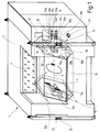
- the processing machine shown in FIGS. 1 and 2 and generally designated 1 has a housing 2, in which a roller 10 is arranged rotatably about an axis A, which is preferably arranged essentially horizontally, and has a polygonal cross section, in the case shown here a hexagonal one Cross section.
- the roller 10, ("turret"), which is preferably designed as a hollow body, is mounted via bearing elements 11a, 11b in guide elements 12a, 12b of a linear guide 12, which are displaceable on a ramp 3 connected to the housing 2.
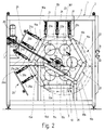
- the roller 10 can be rotated about the axis A by a rotary drive 13 in the direction of the arrow P and can be displaced in the direction of the double arrow V by the linear guide 12 to move the machining tools shown in more detail in FIG. 2.
- the lateral surfaces 10a-10f of the roller 10, delimited by end faces 10a, 10b with relief bores 16 and 17, are designed as fastening surfaces for workpiece receptacles 15a-15f (not shown in FIG. 1) (see FIG. 2).
- the processing machine 1 has a switch 31 for a one-hand start and a switch 32 for an emergency stop of the processing machine 1. Furthermore, a main switch 33 and operating switch 34a-34d and control buttons 35a-35d and two light indicators 36 and 37 are available.
- the roller 10 is rotated further until the workpiece holder 15a and thus the workpiece received therein under the machining tools 23a-23c of a first machining station 23, e.g. B. comes to rest under the welding elements of a first welding station.
- the processing tools 23a-23c of the first processing station 23 which can preferably be delivered via feed units 21, correspondingly process, in particular weld, the first workpiece placed in the workpiece holder 15a, a further workpiece is inserted into the second workpiece holder 15b fastened on the second lateral surface 10b. It is advantageous here that the processing station 23 and the loading station 22 are separated by a partition 7, preferably made of plexiglass, which can be seen in particular in FIG. 1.
- the roller 10 is moved further by a corresponding rotation until the first workpiece receptacle 15a are located under the machining tools 24a-24c of a second machining station 24.
- the workpiece received in the first workpiece holder 15a is processed by the machining tools 24a-24c of the second machining station 24 and the second workpiece located in the second workpiece holder 15b is machined by the machining tools 23a-23c of the first machining station 23.
- the third workpiece holder 10c fastened on the third lateral surface 10c of the roller 10 is in the loading station 22 in its loading position which is accessible from the outside, so that a third workpiece can be inserted into the third workpiece holder 15c while the first two workpieces are being removed from the processing tools 24a-24c or 23a-23c of the second or the first processing station 23 or 24 are processed.
- the first workpiece accommodated in the first workpiece holder 15a is placed under two machining tools 25a, 25b of a third machining station 25, the second workpiece accommodated in the second workpiece holder 15b under the machining tools 24a-24c of the second machining station 24 , the third workpiece received in the third workpiece holder 15c is moved into the loading position 22 into the loading station 22 under the machining tools 23a-23c of the first machining station 23 and the fourth workpiece holder 15d.
- the machining process to be carried out by the machining machine 1 on the first workpiece is ended.
- the first workpiece received in the first workpiece holder 15a is moved further by a division of the roller 10 and is positioned in an unloading station 26 which, as can be seen from FIG. 2, is preferably arranged in such a way that that it forms the bottom station of stations 22-26 of processing machine 1. If the holding of the first workpiece in the first workpiece receptacle 15a is now released in a known manner, the first workpiece falls with the visible side upward onto a conveyor device, not shown in the figures, and can be easily removed from the processing machine 1 in this way.
- the workpiece receptacles 15a-15f are open at the bottom in this position, so that dirt or other impurities fall out of the corresponding workpiece receptacle in an advantageous manner.
- the second workpiece which was received in the second workpiece holder 15b, and which was previously has been processed by the processing tools 25a, 25b of the third processing station 25, moved into the removal station 26 and, as described above, released from it and transported away.
- the first workpiece holder 15a is in this cycle in an empty station 27 and is transported again to the loading station 22 in the following cycle in order to pick up a first workpiece again.
- the rotation of the roller 10 caused by the rotary drive 13 is essentially freely programmable and can also include odd substeps. It is advantageous to provide that all movements of the roller 10 have a sinusoidal rotation sequence, which advantageously causes the movements of the roller 10 to run smoothly and smoothly and without jolts.
Abstract
Description
Die Erfindung betrifft eine Bearbeitungsmaschine, insbesondere eine Schweißmaschine, die mindestens eine Beladestation, mindestens eine Bearbeitungsstation und mindestens eine Entladestation für die von der Bearbeitungsmaschine zu bearbeitenden Werkstück aufweist, wobei die Werkstücke von der mindestens einen Beladestation über die mindestens eine Bearbeitungsstation zu der mindestens einen Entladestation von einer Werkstück-Transporteinheit transportierbar sind.The invention relates to a processing machine, in particular a welding machine, which has at least one loading station, at least one processing station and at least one unloading station for the workpiece to be processed by the processing machine, the workpieces from the at least one loading station via the at least one processing station to the at least one unloading station can be transported by a workpiece transport unit.
Derartige Bearbeitungsmaschinen sind bekannt und sind entweder als Durchlaufanlagen oder als Rundschalttischanlagen ausgebildet. Bei den Durchlaufanlagen werden die von der Bearbeitungsmaschine zu bearbeitenden Werkstücke aus einer Werkstückaufnahme einer Beladestation entnommen und über ein Fördersystem in die Werkstückaufnahme der der Beladestation folgenden Bearbeitungsstation eingelegt. Nachdem der von der ersten der meistens in Linie angeordneten Bearbeitungsstationen auszuführende Bearbeitungsvorgang durchgeführt wurde, wird das Werkstück von der Werkstückaufnahme der ersten Bearbeitung in die Werkstückaufnahme der darauffolgenden Bearbeitungsstation, etc. transportiert und schließlich in der die letzte Station der Durchlaufanlage ausbildenden Entladestation abgelegt.Processing machines of this type are known and are designed either as continuous systems or as rotary indexing systems. In the continuous systems, the workpieces to be processed by the processing machine are removed from a workpiece holder of a loading station and, via a conveyor system, into the workpiece holder of those following the loading station Processing station inserted. After the machining operation to be carried out by the first machining station, which is usually arranged in a line, the workpiece is transported from the workpiece holder of the first machining to the workpiece holder of the subsequent machining station, etc. and finally placed in the unloading station that forms the last station of the continuous system.
Eine derartige Anordnung besitzt den Nachteil, daß die zu bearbeitenden Werkstücke nicht in einer einzigen Werkstückaufnahme verbleiben, sondern vielmehr sukzessive eine Vielzahl von verschiedenen Werkstückaufnahmen durchlaufen. Dies bedeutet, daß in nachteiliger Art und Weise die Werkstücke in den einzelnen Werkstückaufnahmen immer wieder aufs neue positioniert werden müssen. Diese Vorgehensweise bringt nicht nur in nachteiliger Art und Weise mit sich, daß hierfür ein komplexer Positioniermechanismus für jede Werkstückaufnahme vorgesehen werden muß. Vielmehr wird hierdurch auch die Taktzeit verlangsamt, da der immer wieder durchzuführende Positioniervorgang zeitaufwendig ist. Dies ist insbesondere von Nachteil, da bei den Durchlaufanlagen bereits der Werkstücktransport und das hierzu erforderliche Greifen des Werkstücks eine nicht unbeträchtliche Zeit in Anspruch nimmt.Such an arrangement has the disadvantage that the workpieces to be machined do not remain in a single workpiece holder, but rather successively pass through a large number of different workpiece holders. This means that the workpieces in the individual workpiece holders have to be repositioned again and again in a disadvantageous manner. This procedure not only has the disadvantage that a complex positioning mechanism must be provided for each workpiece holder. Rather, this also slows down the cycle time, since the positioning process that has to be carried out again and again is time-consuming. This is particularly disadvantageous, since in the continuous systems the workpiece transport and the gripping of the workpiece required for this take a considerable amount of time.
Ein weiterer Nachteil der bekannten Durchlaufanlage besteht darin, daß diese Anlagen aufgrund der hierbei vorzusehenden Linienbearbeitung sehr lang bauen.Another disadvantage of the known continuous system is that these systems are very long due to the line processing to be provided here.
Desweiteren ist bei den bekannten Durchlaufanlagen von Nachteil, daß die Werkstückaufnahmen nach oben offen sind, so daß sich in nachteiliger Art und Weise Schmutz oder andere Verunreinigungen in den Werkstückaufnahmen ansammeln können.Furthermore, it is disadvantageous in the known continuous systems that the workpiece holders are open at the top, so that dirt or other contaminants can accumulate in the workpiece holders in a disadvantageous manner.
Außerdem ist noch nachteilig, daß beim Entladen der Werkstücke aus der Entladestation das zu bearbeitende Werkstück um 180° gedreht werden muß, damit beim Abtransport die Sichtseite des Werkstücks nach oben liegt.Another disadvantage is that when the workpieces are unloaded from the unloading station, the workpiece to be machined has to be rotated through 180 ° so that the visible side of the workpiece is upward during removal.
Aus der DE 41 25 961 ist eine als Durchlaufanlage konzipierte Bearbeitungsmaschine bekannt, die ein Transfersystem aufweist, bei der mehrere Bearbeitungsstationen entlang des linearen Transfersystems angeordnet sind. Das Transfersystem weist ein durch zwei parallel im Abstand zueinander angeordnete Auflageleisten ausgebildetes Bett auf, auf dem eine Werkstückpalette dadurch verschiebbar ist, indem diese durch eine Taktstange angetrieben wird, die eine Vorschubbewegung in der Taktrichtung der linear aufgebauten Bearbeitungsmaschine ausführt. Die Werkstückpalette besitzt einen polygonalen Querschnitt. Auf jeder der Seitenflächen der Werkstückpalette sind Auflageplätze für Werkstücke vorgesehen.DE 41 25 961 discloses a processing machine designed as a continuous system which has a transfer system in which a plurality of processing stations are arranged along the linear transfer system. The transfer system has a bed formed by two parallel, spaced-apart support strips, on which a workpiece pallet is displaceable by being driven by a clock bar which carries out a feed movement in the clockwise direction of the linearly constructed processing machine. The workpiece pallet has a polygonal cross section. Support spaces for workpieces are provided on each of the side surfaces of the workpiece pallet.
Zur Bearbeitung der Werkstücke durch die Bearbeitungsstationen der Bearbeitungsmaschine ist vorgesehen, daß Werkstücke in der nach oben weisenden Seitenfläche der Werkstückpalette eingesetzt werden und vom Transfersystem, in der Werkstückpalette aufgenommen, zu den einzelnen Bearbeitungsstationen der Bearbeitungsmaschine bewegt werden, ohne daß die Werkstückpalette mit polygonalem Querschnitt um ihre Achse bewegt wird. Zwar bleiben bei der aus der o.g. Druckschrift bekannten Bearbeitungsmaschine die Werkstücke während des Bearbeitungsprozesses in ihren Werkstückaufnahmen, jedoch besitzt die bekannte Bearbeitungsmaschine immer noch den Nachteil, daß sich in nachteiliger Art und Weise in den Werkstückaufnahmen Schmutz oder andere Verunreinigungen ansammeln können, da die Werkstückpalette mit polygonalem Querschnitt während eines Bearbeitungsvorgangs nicht gedreht wird, so daß immer die gleichen Werkstückaufnahmen nach oben zeigen.For processing the workpieces by the processing stations of the processing machine, it is provided that workpieces are inserted in the upward-facing side surface of the workpiece pallet and are moved from the transfer system, incorporated in the workpiece pallet, to the individual processing stations of the processing machine without the workpiece pallet having a polygonal cross section their axis is moved. Although with the from the above Documentation known processing machine the workpieces in their workpiece receptacles during the machining process, however, the known processing machine still has the disadvantage that dirt or other contaminants can accumulate disadvantageously in the workpiece receptacles, since the workpiece pallet with a polygonal cross section is not rotated during a machining operation so that the same workpiece holders always point upwards.
Sollen nun andere Werkstücke bearbeitet werden, so wird die Werkstückpalette mit polygonalem Querschnitt so lange gedreht, bis die entsprechenden Werkstückaufnahmen nach oben zeigen. In dieser Position wird nun die Werkstückpalette auf das Bett aufgesetzt und die entsprechenden Werkstücke werden in die Werkstückaufnahmen der nach oben zeigenden Seitenfläche eingesetzt. Danach wird die Werkstückpalette mit den aufzunehmenden Werkstücken wie oben beschrieben in linearer Weise durch die von der Taktstange ausgeübten linearen Vorschubbewegungen zu den einzelnen Bearbeitungsstationen der bekannten Bearbeitungsmaschine bewegt.If other workpieces are now to be machined, the workpiece pallet with a polygonal cross section is rotated until the corresponding workpiece holders point upwards. In this position, the workpiece pallet is now placed on the bed and the corresponding workpieces are inserted into the workpiece holders on the side surface pointing upwards. Thereafter, the workpiece pallet with the workpieces to be picked up is linearized as described above by the linear ones exerted by the clock bar Feed movements to the individual processing stations of the known processing machine moves.
Die andere der beiden o.g. Gruppen von Bearbeitungsmaschinen, die sogenannten Rundschalttischanlagen, sind dadurch charakterisiert, daß der Werkstücktransport von der Beladestation zu der ersten Bearbeitungsstation, zwischen den einzelnen Bearbeitungsstationen und von der letzten Bearbeitungsstation zu der EntladestatiDie andere der beiden o.g. Gruppen von Bearbeitungsmaschinen, die sogenannten Rundschalttischanlagen, sind dadurch charakterisiert, daß der Werkstücktransport von der Beladestation zu der ersten Bearbeitungsstation, zwischen den einzelnen Bearbeitungsstationen und von der letzten Bearbeitungsstation zu der Entladestation mittels eines Drehtellers erfolgt, auf dem die Werkstückaufnahmen angeordnet sind. Die Bearbeitungsstationen sind hierbei über dem Drehteller angeordnet, was in nachteiliger Art und Weise mit sich bringt, daß mit der Anzahl der Beladestationen der Bearbeitungsmaschine der Durchmesser des Drehtellers rasch zunimmt. Dieses Ansteigen des Durchmessers des Drehtellers bewirkt, daß das Trägheitsmoment der Anordnung quadratisch ansteigt, so daß die Drehgeschwindigkeit, mit der die Werkstücke zwischen den einzelnen Stationen der Rundschalttischanlage transportiert werden können, reduziert werden muß, um die mechanischen Belastungen in akzeptablen Grenzen zu halten, woraus eine langsame Taktgeschwindigkeit resultiert.The other of the two above Groups of processing machines, the so-called rotary indexing systems, are characterized in that the workpiece transport from the loading station to the first processing station, between the individual processing stations and from the last processing station to the unloading station. Groups of processing machines, the so-called rotary indexing systems, are characterized in that the workpiece is transported from the loading station to the first processing station, between the individual processing stations and from the last processing station to the unloading station by means of a turntable on which the workpiece holders are arranged. The processing stations are arranged above the turntable, which has the disadvantage that the diameter of the turntable increases rapidly with the number of loading stations of the processing machine. This increase in the diameter of the turntable causes the moment of inertia of the arrangement to increase quadratically, so that the rotational speed at which the workpieces can be transported between the individual stations of the rotary indexing system must be reduced in order to keep the mechanical loads within acceptable limits, which is why a slow clock speed results.
Desweiteren besitzen auch die Rundschalttischanlagen den Nachteil, daß ihre Werkstückaufnahmen nach oben offen sind, so daß das bereits angesprochene Verunreinigungsproblem auch bei diesen unvermindert auftritt. Desweiteren muß auch bei den Rundschalttischanlagen das Werkstück um 180° gedreht werden, damit dessen Sichtseite beim Abtransport nach oben liegt.Furthermore, the rotary indexing systems also have the disadvantage that their workpiece receptacles are open at the top, so that the contamination problem mentioned above also occurs unabated in these. Furthermore, with rotary indexing systems, the workpiece must also be rotated by 180 ° so that its visible side is up when it is removed.
Es ist daher Aufgabe der Erfindung, eine Bearbeitungsmaschine, insbesondere eine Schweißmaschine, der eingangs genannten Art derart weiterzubilden, daß in besonders einfacher Art und Weise erreicht wird, daß die erfindungsgemäße Bearbeitungsmaschine kompakt baut und ein Werkstück während des gesamten Bearbeitungszyklus in einer einzigen Werkstückaufnahme verbleiben kann.It is therefore an object of the invention to develop a processing machine, in particular a welding machine, of the type mentioned at the outset in such a way that it is achieved in a particularly simple manner that the processing machine according to the invention is compact and a workpiece can remain in a single workpiece holder during the entire machining cycle .
Diese Aufgabe wird erfindungsgemäß dadurch gelöst, daß die die Werkstücke zwischen den Stationen der Bearbeitungsmaschine transportierende Werkstück-Transporteinrichtung als eine um eine Drehachse drehbare Walze mit polygonalem Querschnitt ausgebildet ist, daß mindestens eine Mantelfläche des Körpers als eine Befestigungsfläche für eine Werkstückaufnahme ausgebildet ist, und daß die mindestens eine Beladestation, die mindestens eine Bearbeitungsstation und die mindestens eine Entladestation im wesentlichen entlang des Umfangs der Walze mit polygonalem Querschnitt angeordnet sind.This object is achieved in that the workpiece transport device transporting the workpieces between the stations of the processing machine is designed as a roller rotatable about an axis of rotation with a polygonal cross section, that at least one lateral surface of the body is designed as a fastening surface for a workpiece holder, and that the at least one loading station, the at least one processing station and the at least one unloading station are arranged substantially along the circumference of the roller with a polygonal cross section.
Durch die erfindungsgemäßen Maßnahmen wird in vorteilhafter Art und Weise eine insbesondere für einen Einsatz als Schweißmaschine geeignete Bearbeitungsmaschine ausgebildet, die sich durch ihren kompakten Aufbau und ihre hohe Taktrate auszeichnet. Da die Werkstücke während des gesamten Bearbeitungszyklus in einer einzigen Werkstückaufnahme verbleiben, ist in vorteilhafter Art und Weise kein Positioniervorgang für die einzelnen Werkstücke an den einzelnen Stationen der Bearbeitungsmaschine erforderlich, wodurch eine hohe Taktzeit erreicht werden kann. Durch die zu der Drehachse des Befestigungsflächen für die Werkstückaufnahmen ausbildenden Körpers mit polygonalem Querschnitt und zentrisch angeordneten Bearbeitungsstationen wird ein besonders kompakter Aufbau erreicht, wobei das Trägheitsmoment der erfindungsgemäßen Walze mit polygonalem Querschnitt der erfindungsgemäßen Bearbeitungsmaschine deutlich geringer ist als dasjenige der bekannten Rundschalttischanlagen. Hieraus resultiert, daß in vorteilhafter Art und Weise eine hohe Oralgeschwindigkeit möglich ist.The measures according to the invention advantageously form a processing machine which is particularly suitable for use as a welding machine and is distinguished by its compact structure and its high cycle rate. Since the workpieces remain in a single workpiece holder during the entire machining cycle, advantageously no positioning process for the individual workpieces at the individual stations of the processing machine is required, as a result of which a high cycle time can be achieved. The body with a polygonal cross section and centrically arranged processing stations, which forms the axis of rotation of the fastening surfaces for the workpiece receptacles, achieves a particularly compact structure, the moment of inertia of the roller according to the invention with a polygonal cross section of the processing machine according to the invention being significantly lower than that of the known rotary indexing systems. The result of this is that a high oral speed is advantageously possible.
Eine vorteilhafte Weiterbildung der Erfindung sieht vor, daß die Achse der Walze mit polygonalem Querschnitt im wesentlichen horizontal angeordnet ist. Eine derartige Maßnahme besitzt den Vorteil, daß sich die Werkstückaufnahmen selbsttätig von losem Schmutz und Partikeln befreien.An advantageous development of the invention provides that the axis of the roller with a polygonal cross section is arranged essentially horizontally. Such a measure has the advantage that the workpiece holders automatically clear loose dirt and particles.
Eine weitere vorteilhafte Weiterbildung der Erfindung sieht vor, daß die Entladestation als unterste Station der Bearbeitungsmaschine angeordnet ist. Eine derartige Anordnung besitzt den Vorteil, daß die Werkstücke mit der Sichtseite nach oben auf ein geeignetes Fördermittel abgelegt werden können, ohne daß hierzu ein zeitraubender und kompliziert durchzuführender Wendevorgang um 180° erforderlich ist.Another advantageous development of the invention provides that the unloading station is arranged as the bottom station of the processing machine. A Such an arrangement has the advantage that the workpieces can be placed face-up on a suitable conveying means without the need for a time-consuming and complicated turning process of 180 °.
Eine weitere vorteilhafte Weiterbildung der Erfindung sieht vor, daß die Beladestation von den Bearbeitungsstationen über Abschottungen getrennt ist. Eine derartige Konstruktionsweise besitzt den Vorteil, daß ein Bestücken der erfindungsgemäßen Bearbeitungsmaschine während des Bearbeitungsvorgangs der bereits in der Maschine befindlichen Werkstücke möglich ist, so daß in vorteilhafter Art und Weise eine Durchlaufproduktion, bei der in jedem Takt ein Fertigteil entsteht, gewährleistet ist.Another advantageous development of the invention provides that the loading station is separated from the processing stations by means of partitions. Such a construction has the advantage that it is possible to equip the processing machine according to the invention during the processing operation of the workpieces already in the machine, so that continuous production in which a finished part is produced in each cycle is advantageously ensured.
Eine weitere vorteilhafte Weiterbildung der Erfindung sieht vor, daß die Bewegungen der erfindungsgemäßen Werkstück-Transporteinrichtung der erfindungsgemäßen Bearbeitungsmaschine einen sinoiden Bewegungsablauf aufweisen, so daß diese in vorteilhafter Weise harmonisch und ruck- und stoßfrei verlaufen.A further advantageous development of the invention provides that the movements of the workpiece transport device according to the invention of the processing machine according to the invention have a sinusoidal movement sequence, so that they advantageously run smoothly and smoothly and without jolts.
Eine weitere vorteilhafte Weiterbildung der Erfindung sieht vor, daß die Walze mit polygonalem Querschnitt der erfindungsgemäßen Bearbeitungsmaschine über einen Sicherheitslichtvorhang abgesichert ist.A further advantageous development of the invention provides that the roller with a polygonal cross section of the processing machine according to the invention is secured by a safety light curtain.
Weitere vorteilhafte Weiterbildungen der Erfindung sind Gegenstand der Unteransprüche.Further advantageous developments of the invention are the subject of the dependent claims.
Weitere Einzelheiten und Vorteile der Erfindung sind dem Ausführungsbeispiel zu entnehmen, das im folgenden anhand der Figuren beschrieben wird. Es zeigen:
Figur 1- ein erstes Ausführungsbeispiel einer Bearbeitungsmaschine,
Figur 2- eine Ansicht des Ausführungsbeispiels aus der Richtung II der
Figur 1
- Figure 1
- a first embodiment of a processing machine,
- Figure 2
- a view of the embodiment from the direction II of Figure 1
Die in den Figuren 1 und 2 dargestellte und allgemein mit 1 bezeichnete Bearbeitungsmaschine weist ein Gehäuse 2 auf, in dem um eine vorzugsweise im wesentlichen horizontal angeordnete Achse A drehbar eine Walze 10 angeordnet ist, die einen polygonalen Querschnitt, in dem hier gezeigten Fall einen sechseckigen Querschnitt, aufweist. Die vorzugsweise als Hohlkörper ausgebildete Walze 10, ("Revolver"), ist über Lagerelemente 11a, 11b in Führungselementen 12a, 12b einer Linearführung 12 gelagert, welche auf einer mit dem Gehäuse 2 verbundenen Rampe 3 verschiebbar sind. Die Walze 10 ist durch einen Drehantrieb 13 in Richtung des Pfeiles P um die Achse A drehbar und durch die Linearführung 12 zum Freifahren der in Fig. 2 näher dargestellten Bearbeitungswerkzeuge in Richtung des Doppelpfeils V verschiebbar. Die durch Stirnflächen 10a, 10b mit Erleichterungsbohrungen 16 und 17 begrenzten Mantelflächen 10a-10f der Walze 10 sind als Befestigungsflächen für in Figur 1 nicht dargestellte Werkstückaufnahmen 15a-15f (s. Fig.2) ausgebildet.The processing machine shown in FIGS. 1 and 2 and generally designated 1 has a
Wie desweiteren noch aus Figur 1 ersichtlich ist, weist die Bearbeitungsmaschine 1 einen Schalter 31 für einen Einhandstart sowie einen Schalter 32 für eine Notausschaltung der Bearbeitungsmaschine 1 auf. Desweiteren sind ein Hauptschalter 33 und Bedienschalter 34a-34d sowie Bedienknöpfe 35a-35d sowie zwei Leuchtanzeigen 36 und 37 vorhanden.As can also be seen from FIG. 1, the
Die Funktionsweise der Bearbeitungsmaschine 1 wird nun anhand der in Figur 2 enthaltenen Seitenansicht der Maschine erläutert, aus der auch die in Figur 1 nicht gezeigten Erleichterungsbohrungen 17 an der linken Stirnfläche 10a der Walze 10 dargestellt sind.The operation of the
Nachdem die Walze 10 durch eine entsprechende Verschiebebewegung der Führungselemente 12a, 12b der Linearführung 12, welche durch einen an der Rückwand 2' des Gehäuses 2 angebrachten Getriebebremsmotor 20, welcher über Pleuelstangen 21a, 21b die Führungselemente 12a, 12b der Linearführung 12 antreibt, aus ihrer in Figur 2 strichliert dargestellten Stellung - der Freifahrstellung für die Bearbeitungswerkzeuge der nachstehend näher beschriebenen Stationen - in die in Figur 2 durchgezogen gezeigte Arbeitsstellung bewegt wurde, wird ein erstes Werkstück (nicht gezeigt) in einer Beladestation 22 in die auf der Mantelfläche 10a der Walze 10 befestigte Werkstückaufnahme 15a eingelegt. Durch eine entsprechende Antriebsbewegung des Drehantriebs 13 wird die Walze 10 derart weitergedreht, bis die Werkstückaufnahme 15a und somit das in ihr aufgenommene Werkstück unter den Bearbeitungswerkzeugen 23a-23c einer ersten Bearbeitungsstation 23, z. B. unter den Schweißelementen einer ersten Schweißstation, zu liegen kommt. Während die vorzugsweise über Vorschubeinheiten 21 zustellbaren Bearbeitungswerkzeuge 23a-23c der ersten Bearbeitungsstation 23 das in der Werkstückaufnahme 15a abgelegte erste Werkstück entsprechend bearbeiten, insbesondere schweißen, wird in die auf der zweiten Mantelfläche 10b befestigte zweite Werkstückaufnahme 15b ein weiteres Werkstück einlegt. Hierbei ist von Vorteil, daß die Bearbeitungsstation 23 und die Beladestation 22 durch eine insbesonders aus Fig. 1 ersichtliche Abschottung 7 - vorzugsweise aus Plexiglas - getrennt sind.After the
Nachdem der Bearbeitungsvorgang des in der ersten Werkstückaufnahme 15a aufgenommenen ersten Werkstücks beendet wurde, wird durch eine entsprechende Drehung der Walze 10 diese weiterbewegt, bis die erste Werkstückaufnahme 15a sich unter den Bearbeitungswerkzeugen 24a-24c einer zweiten Bearbeitungsstation 24 befinden. Nun werden das in der ersten Werkstückaufnahme 15a aufgenommene Werkstück durch die Bearbeitungswerkzeuge 24a-24c der zweiten Bearbeitungsstation 24 und das in der zweiten Werkstückaufnahme 15b befindliche zweite Werkstück von den Bearbeitungswerkzeugen 23a-23c der ersten Bearbeitungsstation 23 bearbeitet.After the machining process of the first workpiece accommodated in the
Zu diesem Zeitpunkt befindet sich die auf der dritten Mantelfläche 10c der Walze 10 befestigte dritte Werkstückaufnahme 10c in der Beladestation 22 in ihrer von außen zugänglichen Beladestellung, so daß in die dritte Werkstückaufnahme15c ein drittes Werkstück eingelegt werden kann, während die ersten beiden Werkstücke von den Bearbeitungswerkzeugen 24a-24c bzw. 23a-23c der zweiten bzw. der ersten Bearbeitungsstation 23 bzw. 24 bearbeitet werden.At this time, the
In entsprechender Art und Weise werden im nächsten Takt des Bearbeitungszyklus das in der ersten Werkstückaufnahme 15a aufgenommene erste Werkstück unter zwei Bearbeitungswerkzeuge 25a, 25b einer dritten Bearbeitungsstation 25, das in der zweiten Werkstückaufnahme 15b aufgenommene zweite Werkstück unter die Bearbeitungswerkzeuge 24a-24c der zweiten Bearbeitungsstation 24, das in der dritten Werkstückaufnahme 15c aufgenommene dritte Werkstück unter die Bearbeitungswerkzeuge 23a-23c der ersten Bearbeitungsstation 23 und die vierte Werkstückaufnahme 15d in ihre Beladestellung in die Beladestation 22 bewegt.In a corresponding manner, in the next cycle of the machining cycle, the first workpiece accommodated in the
Nachdem der Bearbeitungsvorgang des ersten Werkstücks durch die beiden Bearbeitungswerkzeuge 25a, 25b der dritten Bearbeitungsstation 25 beendet wurde, ist der von der Bearbeitungsmaschine 1 am ersten Werkstück vorzunehmende Bearbeitungsprozeß beendet.After the machining process of the first workpiece has been ended by the two
Im darauffolgenden fünften Takt wird durch eine entsprechende Drehung der Walze 10 das in der ersten Werkstückaufnahme 15a aufgenommene erste Werkstück um eine Teilung der Walze 10 weiterbewegt und wird derart in einer Entladestation 26 positioniert, welche - wie aus Figur 2 ersichtlich ist - vorzugweise derart angeordnet, daß sie die unterste Station der Stationen 22-26 der Bearbeitungsmaschine 1 ausbildet. Wird nun die Halterung des ersten Werkstücks in der ersten Werkstückaufnahme 15a auf bekannte Art und Weise gelöst, so fällt das erste Werkstück mit der Sichtseite nach oben auf eine in den Figuren nicht dargestellte Fördereinrichtung und kann derart leicht aus der Bearbeitungsmaschine 1 abtransportiert werden.In the following fifth cycle, by a corresponding rotation of the
Hierbei ist von Vorteil, daß die Werkstückaufnahmen 15a-15f in dieser Position nach unten offen sind, so daß in vorteilhafter Art und Weise Schmutz oder andere Verunreinigungen von selbst aus der entsprechenden Werkstückaufnahme herausfallen.It is advantageous here that the
Im darauffolgenden sechsten Takt des Bearbeitungszyklus wird das in der zweiten Werkstückaufnahme 15b aufgenommene zweite Werkstück, welches zuvor durch die Bearbeitungswerkzeuge 25a, 25b der dritten Bearbeitungsstation 25 bearbeitet wurde, in die Entnahmestation 26 bewegt und wie oben beschrieben aus dieser gelöst und abtransportiert. Die erste Werkstückaufnahme 15a befindet sich in diesem Takt in einer Leerstation 27 und wird im darauffolgenden Takt wieder zur Beladestation 22 transportiert, um erneut ein erstes Werkstück aufzunehmen.In the subsequent sixth cycle of the machining cycle, the second workpiece, which was received in the
Abschließend ist festzustellen, daß die beschriebene Ausgestaltung der Bearbeitungsmaschine 1 mit einer Beladestation 22, drei Bearbeitungsstationen 23-25, einer Entladestation 26 und einer Leerstation 27 nur beispielhaften Charakter besitzt. Es ist dem Fachmann aus obiger Beschreibung klar ersichtlich, daß - eine entsprechende Teilung der Walze 10 vorausgesetzt - auch mehr oder weniger als sechs Stationen 22-27 vorgesehen werden können, wobei die Aufteilung der Stationen 22-27 der Bearbeitungsmaschine 1 in weiten Grenzen frei gewählt werden kann.In conclusion, it should be noted that the described configuration of the
Es bedarf auch keiner weiteren Erläuterung, daß die durch den Drehantrieb 13 bewirkte Drehung der Walze 10 im wesentlichen frei programmierbar ist und auch ungerade Teilschritte beinhalten kann. Hierbei ist es von Vorteil vorzusehen, daß sämtliche Bewegungen der Walze 10 einen sinoiden Drehungsablauf aufweisen, wodurch in vorteilhafter Art und Weise bewirkt wird, daß die Bewegungen der Walze 10 harmonisch und ruck- und stoßfrei verlaufen.There is also no need for any further explanation that the rotation of the
Claims (19)
Applications Claiming Priority (2)
| Application Number | Priority Date | Filing Date | Title |
|---|---|---|---|
| DE19512552 | 1995-04-06 | ||
| DE1995112552 DE19512552C2 (en) | 1995-04-06 | 1995-04-06 | Processing machine, in particular welding machine |
Publications (1)
| Publication Number | Publication Date |
|---|---|
| EP0736359A1 true EP0736359A1 (en) | 1996-10-09 |
Family
ID=7758723
Family Applications (1)
| Application Number | Title | Priority Date | Filing Date |
|---|---|---|---|
| EP96105391A Withdrawn EP0736359A1 (en) | 1995-04-06 | 1996-04-04 | Machine tool with indexable workholding drum |
Country Status (2)
| Country | Link |
|---|---|
| EP (1) | EP0736359A1 (en) |
| DE (1) | DE19512552C2 (en) |
Cited By (7)
| Publication number | Priority date | Publication date | Assignee | Title |
|---|---|---|---|---|
| DE19936502C1 (en) * | 1999-08-05 | 2001-02-15 | Bernhard Magerl | Arrangement for pivotable workpiece delivery into machine tool working region has drive spindle connected to holder for fixing drive element with attached rotatable workpiece holders |
| WO2002053305A1 (en) * | 2000-12-28 | 2002-07-11 | Wimetal S.A. (Societe Anonyme) | Device and method for making connections that cross over exhaust devices |
| DE10136202A1 (en) * | 2001-07-25 | 2003-02-06 | Braun Georg | Workpiece holder for mounting of workpieces has two mounting surfaces per workpiece and carrying heads which have a prismatic form with a polygonal cross-section |
| CN104842101A (en) * | 2015-05-05 | 2015-08-19 | 苏州三体智能科技有限公司 | Drum-type welding device |
| DE102015122470A1 (en) * | 2015-06-29 | 2016-12-29 | Alfing Keßler Sondermaschinen GmbH | Machine tool with several tool spindles |
| EP3112085A1 (en) * | 2015-06-29 | 2017-01-04 | Alfing Kessler Sondermaschinen GmbH | Machine tool with a plurality of tool spindles |
| CN106513989A (en) * | 2016-11-28 | 2017-03-22 | 广东天机工业智能系统有限公司 | Rotary laser engraving machine |
Families Citing this family (2)
| Publication number | Priority date | Publication date | Assignee | Title |
|---|---|---|---|---|
| DE102004022212A1 (en) * | 2004-05-04 | 2005-12-01 | Heidelberger Druckmaschinen Ag | Folded box gluer with improved accessibility |
| DE102019108351A1 (en) * | 2019-03-29 | 2020-10-01 | Felsomat Gmbh & Co. Kg | Welding machine, manufacturing system and method for welding free ends of bar conductors |
Citations (4)
| Publication number | Priority date | Publication date | Assignee | Title |
|---|---|---|---|---|
| US2803840A (en) * | 1954-02-08 | 1957-08-27 | Robert C Mcshirley | Machine tool having an oscillatable tool spindle and plural work holders movable in a circular path |
| DE1963209A1 (en) * | 1969-12-17 | 1971-06-24 | Frank Rudolf Dipl Ing | Indexing table or indexing drum machine |
| DE2307396A1 (en) * | 1973-02-15 | 1974-08-22 | Rudolf Dipl-Ing Frank | SHIFT DRUM AUTOMAT |
| US4917708A (en) * | 1987-01-19 | 1990-04-17 | Fuji Seiki Machine Works, Ltd. | Deburring and cleaning apparatus with multi-station rotary drum and reciprocating blasting guns |
Family Cites Families (1)
| Publication number | Priority date | Publication date | Assignee | Title |
|---|---|---|---|---|
| DE4125961C2 (en) * | 1991-08-06 | 1995-04-06 | Giddings & Lewis Gmbh | Workpiece pallet as workpiece carrier for transfer lines |
-
1995
- 1995-04-06 DE DE1995112552 patent/DE19512552C2/en not_active Expired - Lifetime
-
1996
- 1996-04-04 EP EP96105391A patent/EP0736359A1/en not_active Withdrawn
Patent Citations (4)
| Publication number | Priority date | Publication date | Assignee | Title |
|---|---|---|---|---|
| US2803840A (en) * | 1954-02-08 | 1957-08-27 | Robert C Mcshirley | Machine tool having an oscillatable tool spindle and plural work holders movable in a circular path |
| DE1963209A1 (en) * | 1969-12-17 | 1971-06-24 | Frank Rudolf Dipl Ing | Indexing table or indexing drum machine |
| DE2307396A1 (en) * | 1973-02-15 | 1974-08-22 | Rudolf Dipl-Ing Frank | SHIFT DRUM AUTOMAT |
| US4917708A (en) * | 1987-01-19 | 1990-04-17 | Fuji Seiki Machine Works, Ltd. | Deburring and cleaning apparatus with multi-station rotary drum and reciprocating blasting guns |
Cited By (8)
| Publication number | Priority date | Publication date | Assignee | Title |
|---|---|---|---|---|
| DE19936502C1 (en) * | 1999-08-05 | 2001-02-15 | Bernhard Magerl | Arrangement for pivotable workpiece delivery into machine tool working region has drive spindle connected to holder for fixing drive element with attached rotatable workpiece holders |
| WO2002053305A1 (en) * | 2000-12-28 | 2002-07-11 | Wimetal S.A. (Societe Anonyme) | Device and method for making connections that cross over exhaust devices |
| DE10136202A1 (en) * | 2001-07-25 | 2003-02-06 | Braun Georg | Workpiece holder for mounting of workpieces has two mounting surfaces per workpiece and carrying heads which have a prismatic form with a polygonal cross-section |
| CN104842101A (en) * | 2015-05-05 | 2015-08-19 | 苏州三体智能科技有限公司 | Drum-type welding device |
| DE102015122470A1 (en) * | 2015-06-29 | 2016-12-29 | Alfing Keßler Sondermaschinen GmbH | Machine tool with several tool spindles |
| EP3112085A1 (en) * | 2015-06-29 | 2017-01-04 | Alfing Kessler Sondermaschinen GmbH | Machine tool with a plurality of tool spindles |
| CN106513989A (en) * | 2016-11-28 | 2017-03-22 | 广东天机工业智能系统有限公司 | Rotary laser engraving machine |
| CN106513989B (en) * | 2016-11-28 | 2019-04-05 | 广东天机工业智能系统有限公司 | Rotary laser engraving machine |
Also Published As
| Publication number | Publication date |
|---|---|
| DE19512552C2 (en) | 1997-02-13 |
| DE19512552A1 (en) | 1996-10-24 |
Similar Documents
| Publication | Publication Date | Title |
|---|---|---|
| DE3035191C2 (en) | ||
| EP0117557B1 (en) | Workpiece pallet for machine tools | |
| DD140559A5 (en) | MANUFACTURING INSTALLATION FOR COMPONENTS TO BE MADE IN TWO OR MORE STEPS | |
| WO2007059907A1 (en) | Machine tool | |
| DE3304090A1 (en) | EQUIPMENT FOR MOUNTING OR EDITING WORKPIECES | |
| CH656338A5 (en) | ASSEMBLY LINE WITH SEVERAL WORKPLACES. | |
| DE3722180C2 (en) | Transfer machine | |
| DE3141784C2 (en) | Device for feeding and removing stators of electrical machines | |
| EP0967038B1 (en) | Device for machining by material removal of workpieces | |
| DE60009200T2 (en) | Machine tool for processing symmetrical elongated elements such as, for example, components for chairs, furniture or other such objects | |
| EP0266646B1 (en) | Tool magazine for machine tools, and method for its operation | |
| EP0736359A1 (en) | Machine tool with indexable workholding drum | |
| DE3136017C1 (en) | Lathe | |
| DE3540016A1 (en) | Industrial assembly robot | |
| DD201987A5 (en) | TOOLING MACHINE WITH WORKPIECE SUPPLIERS | |
| DE3431349A1 (en) | Apparatus on NC cutting machines for feeding and removing workpieces | |
| EP0073536A2 (en) | Machine for finishing workpiece surfaces | |
| EP0129677A2 (en) | Machining centre for milling and drilling operations | |
| DE3631718A1 (en) | Loading attachment with loading cross | |
| EP0352785A1 (en) | Device for manipulating and storing pallets and pallet-like or other objects | |
| EP1755823B1 (en) | Apparatus for storing and handling tools of a machining center | |
| DE3706122A1 (en) | Method and apparatus for the handling of workpieces and tools required for their machining on machine tools | |
| EP0026285A1 (en) | Transfer table | |
| DE1552770A1 (en) | Device for the automatic loading of machine tools | |
| EP0195844B1 (en) | Device, installation and method for storing, transporting and transferring cylindrical parts |
Legal Events
| Date | Code | Title | Description |
|---|---|---|---|
| PUAI | Public reference made under article 153(3) epc to a published international application that has entered the european phase |
Free format text: ORIGINAL CODE: 0009012 |
|
| AK | Designated contracting states |
Kind code of ref document: A1 Designated state(s): DE ES FR IT |
|
| STAA | Information on the status of an ep patent application or granted ep patent |
Free format text: STATUS: THE APPLICATION IS DEEMED TO BE WITHDRAWN |
|
| 18D | Application deemed to be withdrawn |
Effective date: 19970410 |