EP0736246A1 - A method of positioning means for automatically milking animals, such as cows, as well as an implement for applying same - Google Patents
A method of positioning means for automatically milking animals, such as cows, as well as an implement for applying same Download PDFInfo
- Publication number
- EP0736246A1 EP0736246A1 EP96200879A EP96200879A EP0736246A1 EP 0736246 A1 EP0736246 A1 EP 0736246A1 EP 96200879 A EP96200879 A EP 96200879A EP 96200879 A EP96200879 A EP 96200879A EP 0736246 A1 EP0736246 A1 EP 0736246A1
- Authority
- EP
- European Patent Office
- Prior art keywords
- animal
- reference plane
- milking
- teats
- robot
- Prior art date
- Legal status (The legal status is an assumption and is not a legal conclusion. Google has not performed a legal analysis and makes no representation as to the accuracy of the status listed.)
- Granted
Links
- 241001465754 Metazoa Species 0.000 title claims abstract description 75
- 241000283690 Bos taurus Species 0.000 title claims abstract description 26
- 238000000034 method Methods 0.000 title claims abstract description 18
- 238000010276 construction Methods 0.000 claims abstract description 35
- 230000005484 gravity Effects 0.000 claims abstract description 8
- 210000002445 nipple Anatomy 0.000 claims description 43
- 210000000481 breast Anatomy 0.000 claims description 14
- 210000003141 lower extremity Anatomy 0.000 claims description 5
- 210000001364 upper extremity Anatomy 0.000 claims description 5
- 238000004891 communication Methods 0.000 description 2
- 239000000969 carrier Substances 0.000 description 1
- 230000000694 effects Effects 0.000 description 1
- 230000005662 electromechanics Effects 0.000 description 1
- 230000006870 function Effects 0.000 description 1
- 238000009434 installation Methods 0.000 description 1
- 238000012986 modification Methods 0.000 description 1
- 230000004048 modification Effects 0.000 description 1
- 239000002689 soil Substances 0.000 description 1
Images


Classifications
-
- A—HUMAN NECESSITIES
- A01—AGRICULTURE; FORESTRY; ANIMAL HUSBANDRY; HUNTING; TRAPPING; FISHING
- A01J—MANUFACTURE OF DAIRY PRODUCTS
- A01J7/00—Accessories for milking machines or devices
- A01J7/04—Accessories for milking machines or devices for treatment of udders or teats, e.g. for cleaning
-
- A—HUMAN NECESSITIES
- A01—AGRICULTURE; FORESTRY; ANIMAL HUSBANDRY; HUNTING; TRAPPING; FISHING
- A01J—MANUFACTURE OF DAIRY PRODUCTS
- A01J5/00—Milking machines or devices
- A01J5/017—Automatic attaching or detaching of clusters
- A01J5/0175—Attaching of clusters
Definitions
- the present invention relates to a method of positioning, by means of a robot construction, means for automatically milking animals, such as cows.
- the method is characterized in that the means for automatically milking are positioned in the longitudinal direction of the milking parlour relative to a reference plane situated transversely to said longitudinal direction, in which reference plane the centre of gravity of the relevant animal is located.
- this method is furthermore characterized in that, in the milking parlour, the pressure exercised by the animal with at least one foreleg and one hindleg on the floor thereof and the places on the floor where this pressure is exercised are determined and recorded in a computer, and that in the computer, with the aid of these data, the reference plane is defined.
- the means for automatically milking may be brought in a position relative to the reference plane, that is fixed for all the animals, and, if required, may thereafter be accurately positioned under the animal's teats
- the reference plane and, consequently, the means for automatically milking will move as well.
- the means for automatically milking can be maintained in a fixed position relative to the reference plane.
- the robot construction may be arranged in a fixed position relative to the milking parlour, while, by means of guiding one or more arms of the robot construction, the position of the means for automatically milking may be maintained fixed relative to the reference plane, it is advantageous when the robot construction as a whole is positioned in the longitudinal direction of the milking parlour relative to said reference plane.
- the robot construction When an animal has entered the milking parlour, the robot construction will be brought from an inoperative position into a position defined relative to the reference plane, whereafter, according to the invention, the robot arm, serving as a carrier for the means for automatically milking and constituting part of the robot construction, pivots under the animal from the fixed position that the robot construction has taken relative to the reference plane.
- a detector in particular a laser detector
- the teats will be followed by post-guiding the robot arm by means of the detector, and, as long as the teats have not yet been detected or as soon as the teats are no longer detected, they will be followed by post-guiding the robot arm in the reference plane.
- the invention also relates to an implement for positioning, by means of a robot construction movably arranged in the longitudinal direction of the milking parlour, means for automatically milking animals, such as cows, which implement is provided with elements that are sensitive to pressure, by means of which the pressure exercised by the animal with at least one foreleg and one hindleg on the floor of the milking parlour and the places on the floor where this pressure is exercised are determined and recorded in a computer, which implement is then characterized in that the computer is equipped so as to define, with the aid of these data, a reference plane situated transversely to the longitudinal direction of the milking parlour, in which reference plane the centre of gravity of the relevant animal is located, and to position the means for automatically milking in the longitudinal direction of the milking parlour relative to said reference plane.
- the implement according to the invention is additionally provided with an animal identification system cooperating with the computer, while, for each animal, there is recorded in the computer the position of the udder and/or the teats relative to the reference plane.
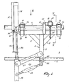
- FIG. 1 In the plan view of the implement as shown in Figure 1, there is represented a cow 1 present in the milking parlour, which is surrounded by a fencing 2 allowing the animal a limited freedom of movement.
- the animal can enter the milking parlour via a longitudinal side near the rear thereof and leave same via the same longitudinal side near the front thereof.
- the front side of the milking parlour being provided with a feeding installation, the cow will advance sufficiently far and will come into a position in which it can be milked easily.
- a fixed frame 3 constituting part of the fencing 2, which frame 3 includes a first frame part 4 and a second frame part 5.
- the first frame part 4 extends parallel to the second frame part 5 and is situated substantially thereabove.
- the first frame part 4 is fixed to the outside of two vertical stands 6 and 7 constituting part of the fencing 2, while the second frame part 5 is fixed therebetween.
- the milking robot 8 comprises a carrier frame 9 for its further parts.
- the carrier frame 9 includes a beam 10 extending substantially parallel to the first frame part 4, a beam 11 directed vertically downwardly perpendicular to the beam 10 and fixed thereto, and two struts 12. Near the ends of the beam 10, there are provided pairs of supporting elements 13. To each pair of supporting elements 13, by means of supporting plates 14 fixed thereto, at an angle of approximately 45° there are provided two rollers 16, constituting a rollers pair 15, in such a way that the carrier frame 9 is suspended easily movably along the upper frame part 4, therebelow. On the beam 10 of the carrier frame 9, on both sides, there are provided two carriers 17, to which there is attached, movably about a pivot shaft 18, a motor 19.
- this motor 19 there is driven a roller 20, preferably having a rubber surface, which roller is pushed against the upper frame part 4 by means of a spring member 21.
- the spring member 21 being active between the motor 19 and the carrier frame 9, the roller 20 to be driven by the motor 19 is kept pushed against the upper frame part 4, so that, when the motor is driven, it will be moved along the upper frame part 4 and, consequently, the entire carrier frame 9 will be moved.
- a non-shown computer it will be possible to guide the milking robot, in the longitudinal direction of the milking parlour, from an inoperative position to a starting position, in which the milking robot arms are moved under the animal present in the milking parlour, and to follow the movements of the animal in the longitudinal direction thereof.
- the milking robot 8 can be moved in the longitudinal direction of the milking parlour in such a way that the distance between the reference plane and the milking robot is brought, respectively maintained, at an adjusted value. In its inoperative position, the milking robot 8 has been moved as rearwardly as possible relative to the frame parts 4 and 5.
- the position of the reference plane will determine that of the animal in the milking parlour in the longitudinal direction thereof, so that, while maintaining the distance in longitudinal direction between the reference plane and the milking robot 8, the latter can follow the movements of the cow in the longitudinal direction of the milking parlour.
- the beam 11 of the carrier frame 9 extends vertically downwardly to somewhat below the second frame part 5. At the lower side of this beam 11, there is disposed a horizontal, rearwardly extending strip 22 which is provided with a freely rotatable roller element 23.
- the lower frame part 5 is constituted by a rail, in particular one designed as a U-shaped beam, while the freely rotatable roller element 23 is arranged in such a way that it is movable between the two upright edges of the U-shaped beam.
- the milking robot 8 is supported against the lower frame part 5 and, when being moved by means of the motor over the first frame part 4, can easily move along the second frame part 5.
- the milking robot comprises a robot construction 24 which, by means of a control cylinder 25, is movable substantially vertically relative to the carrier frame 9.
- the robot construction 24 is movably connected with the carrier frame 9.
- the upper arm 27 of this quadrangle construction 26 has a fixed length, while the lower arm 28 thereof is adjustable in length so as to enable the robot construction 24 to be adjusted to a limited extent.
- the robot construction 24 comprises a substantially vertical robot arm 29 as well as robot arms 30 that are movable in a substantially horizontal plane.
- the robot arm 29 is connected with the beam 11 of the carrier frame 9.
- the control cylinder 25 is active between the carrier frame 9 and the robot arm 29.
- the orientation of the robot arm 29 is slightly adjustable, the spatial position of the action point of the control cylinder 25 at the robot arm 29 is not entirely fixed.
- the housing of the control cylinder 25 is provided, at least pivotably to a limited extent, on a carrier plate 31 attached to the beam 10 of the carrier frame 9. On this carrier plate 31 there are disposed supports 32, wherebetween the housing of the control cylinder 25 is capable of being moved about a pivot shaft 33.
- the control cylinder is designed as a servo-pneumatic positioning cylinder.
- a position feedback rod 36 by means of which, in a part 37 of the control cylinder, a potentiometer will deduce a signal indicating the position of the piston rod relative to the cylinder housing, while, with the aid of the signal supplied by the potentiometer, the position of the piston rod 34 relative to the cylinder housing can be post-guided to a preset position.
- the control cylinder 25 is provided with an overload protection enabling the robot construction 24 to be moved into its lowest position, as soon as the animal present in the milking parlour exercises a pressure thereon, e.g. by kicking.
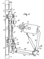
- Figures 2 and 4 show the milking robot 8 in its inoperative position, in which it has been moved as rearwardly as possible and the robot construction 24 has been brought nearest possible to the soil.
- the milking robot 8 is brought from its inoperative position into the starting position, i.e. into the position wherein the arms of the milking robot 8 can be moved to under the cow.
- the milking robot includes arms 38, 39 and 40.
- the arms 38 and 39 are arranged at a fixed angle of 90° relative to each other. Therefore, the arms 38 and 39 are moved together, i.e. by a control cylinder 41 provided between a supporting plate 42 attached to the robot arm 29 and a connecting piece 43 disposed between the two arms 38 and 39.
- the two latter arms are pivotable about a substantially vertical pivot shaft 44 between the supporting plate 42 and a supporting plate 45, which latter is also rigidly connected to the robot arm 29, more in particular at the lower end thereof.
- the arm 40 is pivotable relative to the arm 39 about a substantially vertical pivot shaft 46 and pivots relative thereto by means of a control cylinder 47 disposed between the arm 40 and the end of the arm 39 that is situated near the connecting piece 43.
- a control cylinder 47 disposed between the arm 40 and the end of the arm 39 that is situated near the connecting piece 43.
- the teat cups 48 and 49 Near the end of the arm 39, there are provided the teat cups 48 and 49 to be connected to the teats of the cow.
- a slide which is movable on the arm 40 and on which there is provided a sensor 50 which, by a sectorwise scanning movement, can accurately determine the position of the teats, so that the control cylinders 25, 41 and 47 can be computer-controlled in such a way that the teat cups will be connected properly to the teats.
- the robot arms 38 - 40 having been brought to under the cow, they are in a relatively low position, in which the sensor 50 will not yet detect teats.
- the robot arms 38 - 40 are raised stepwise until the sensor 50 detects one or more teats of the animal.
- the implement as shown in Figure 1 furthermore comprises elements 51 sensitive to pressure which, in the present embodiment, are disposed in the floor 52 of the milking parlour.
- the elements 51 sensitive to pressure are disposed in a lowered part of the floor 52, so that they are situated at the same level therewith. It will be obvious, however, that the elements 51 sensitive to pressure may also be arranged on the floor 52 of the milking parlour.
- the elements 51 sensitive to pressure may be constituted by piezo-elements known per se.
- the elements sensitive to pressure are disposed at four places in the floor 52 of the milking parlour.
- the places where the elements 51 sensitive to pressure are disposed are chosen in such a way that, when an animal enters the milking parlour, it stands with its legs on all four elements sensitive to pressure.
- the elements 51 sensitive to pressure may also be built up by a number of juxtaposed pressure cells, which may be designed as electro-mechanic contacts, as is detailed in EP-A-O 572 068.
- the implement according to the invention is additionally provided with an animal identification system being in communication with the computer of the milking robot.
- the animal identification system is constituted by a sensor 53 arranged near the feeding trough and being in communication with the computer and a transponder 54 disposed around the neck of the cow 1.
- the sensor 53 When a cow enters the milking parlour, the sensor 53 receives from the transponder 54 a code that is unique for the relevant cow. With the aid of said code, the computer connected with the sensor 53 defines which cow has occupied the milking parlour. In the (non-shown) computer, all the known data relating to the animal are retrieved and kept stand by. After the cow has entered the milking parlour, the elements 51 sensitive to pressure are activated due to the fact that the cow has put its legs on said elements 51. The surface of the elements 51 sensitive to pressure being many times larger than that of the underside of the cow's legs, only a number of pressure cells is pressed.
- the pressure cells pressed by the animal's legs supply a signal to the computer, with the aid of which the position of the cow's legs on the floor 52 of the milking parlour can exactly be defined.
- the position of each pressure cell is recorded in the memory of the computer.
- the pressure exercised by the animal's legs is then determined.
- there can be defined in the computer the position of a reference plane in the longitudinal direction of the milking parlour and through the centre of gravity of the animal. When the animal moves, the reference plane moves as well.
- there is recorded in the memory of the computer the position of the udder and/or the teats relative to said reference plane.
- the position of the reference plane having been determined with the aid of the signals supplied by the elements 51 sensitive to pressure, the position of the udder and/or the teats relative to the reference plane for the relevant animal is read out of the memory of the computer.
- the teat cups 48, 49 are guided, by means of the robot construction 24, to the udder and/or the teats. For that purpose, from the position taken by the entire robot construction 24 relative to the reference plane, first the arms 38, 39, 40 pivot under the cow.
- the robot arm 40 will be post-guided in the longitudinal direction in the reference plane, whereafter the teats will again have come within the range of the detector. Due to the fact that, for each animal, the position of the udder and/or the teats relative to the reference plane is known, it will always be possible, when the robot arm 40 has been post-guided in the longitudinal direction to the correct position relative to the reference plane, to make the teats fall within the range of the detector.
Abstract
Description
- The present invention relates to a method of positioning, by means of a robot construction, means for automatically milking animals, such as cows.
- Such a method is known from EP-A-O 519 544. In this document, a plate pushed against the rear side of the animal is used as a reference plane, while, by means of a sensor attached to the robot construction, the position of the latter construction relative to the plate, and consequently relative to the animal, is determined.
- The invention aims at improving this known method in such a way that a plate pushed against the rear side of the animal no longer needs to be used. For that purpose, according to the invention, the method is characterized in that the means for automatically milking are positioned in the longitudinal direction of the milking parlour relative to a reference plane situated transversely to said longitudinal direction, in which reference plane the centre of gravity of the relevant animal is located. In particular, this method is furthermore characterized in that, in the milking parlour, the pressure exercised by the animal with at least one foreleg and one hindleg on the floor thereof and the places on the floor where this pressure is exercised are determined and recorded in a computer, and that in the computer, with the aid of these data, the reference plane is defined. Making use of the pressure exercised by the animal on the floor of the milking parlour and the places on the floor where this pressure is exercised, for the purpose of obtaining position data for automatically milking animals, is known per se from EP-A-O 572 068. In this document, these data are used for determining the position of the udder and/or the teats of the animal, so that, by means of the robot construction, the means for automatically milking can be positioned under the udder of the animal to be milked. There is not used a reference plane through the animal's centre of gravity, whereby, also when the animal moves, the means for automatically milking can be positioned relative to this plane and be maintained in this position. Although the means for automatically milking may be brought in a position relative to the reference plane, that is fixed for all the animals, and, if required, may thereafter be accurately positioned under the animal's teats, it is also possible to record in the computer, for individual animals, the position of the udder and/or the teats relative to the reference plane. In the latter case, it will be desirable to dispose of the possibility to adapt in the computer, if required, the position of the udder and/or the teats of an animal relative to the reference plane, to the actual position the udder and/or the teats appear to have after the teat cups have been connected to the teats of the animal.
- As soon as an animal moves in the milking parlour, in particular makes a step forwards or rearwards, or when the animal, while staying with its legs on the same place, moves more forwardly or rearwardly, the reference plane and, consequently, the means for automatically milking will move as well. In other words: upon moving of the animal in the longitudinal direction of the milking parlour, the means for automatically milking can be maintained in a fixed position relative to the reference plane. Although the robot construction may be arranged in a fixed position relative to the milking parlour, while, by means of guiding one or more arms of the robot construction, the position of the means for automatically milking may be maintained fixed relative to the reference plane, it is advantageous when the robot construction as a whole is positioned in the longitudinal direction of the milking parlour relative to said reference plane.
- When an animal has entered the milking parlour, the robot construction will be brought from an inoperative position into a position defined relative to the reference plane, whereafter, according to the invention, the robot arm, serving as a carrier for the means for automatically milking and constituting part of the robot construction, pivots under the animal from the fixed position that the robot construction has taken relative to the reference plane. In a particular embodiment according to the invention, there is provided on the said robot arm a detector, in particular a laser detector, while, after the detector has been brought under the animal in a position in which the teats of the animal can be detected, upon moving of the animal, the teats will be followed by post-guiding the robot arm by means of the detector, and, as long as the teats have not yet been detected or as soon as the teats are no longer detected, they will be followed by post-guiding the robot arm in the reference plane.
- Besides to a method, the invention also relates to an implement for positioning, by means of a robot construction movably arranged in the longitudinal direction of the milking parlour, means for automatically milking animals, such as cows, which implement is provided with elements that are sensitive to pressure, by means of which the pressure exercised by the animal with at least one foreleg and one hindleg on the floor of the milking parlour and the places on the floor where this pressure is exercised are determined and recorded in a computer, which implement is then characterized in that the computer is equipped so as to define, with the aid of these data, a reference plane situated transversely to the longitudinal direction of the milking parlour, in which reference plane the centre of gravity of the relevant animal is located, and to position the means for automatically milking in the longitudinal direction of the milking parlour relative to said reference plane. In a practical embodiment of such an implement, there are disposed elements sensitive to pressure in or on the floor of the milking parlour, at those places where the animal can put its legs. Although it is sufficient to dispose elements sensitive to pressure on the place where the animal can stand with only one hindleg and only one foreleg, it is advantageous to dispose these elements at those places where the animal can stand with all its legs. The implement according to the invention is additionally provided with an animal identification system cooperating with the computer, while, for each animal, there is recorded in the computer the position of the udder and/or the teats relative to the reference plane.
- For a better understanding of the invention and to show how the same may be carried into effect, reference will now be made, by way of example, to the accompanying drawings, in which:
- Figure 1 shows, in plan view, the implement according to the invention, in which there are brought arms of the robot construction under an animal present in the milking parlour;
- Figure 2 is a side view of the implement shown in Figure 1, in which the robot construction is in the inoperative position, and
- Figures 3 to 8 show more in detail various parts of the implement represented in Figures 1 and 2.
- In the plan view of the implement as shown in Figure 1, there is represented a cow 1 present in the milking parlour, which is surrounded by a
fencing 2 allowing the animal a limited freedom of movement. The animal can enter the milking parlour via a longitudinal side near the rear thereof and leave same via the same longitudinal side near the front thereof. The front side of the milking parlour being provided with a feeding installation, the cow will advance sufficiently far and will come into a position in which it can be milked easily. At the other longitudinal side of the milking parlour, being opposite to the one including the entrance and exit, there is provided afixed frame 3 constituting part of thefencing 2, whichframe 3 includes afirst frame part 4 and asecond frame part 5. Thefirst frame part 4 extends parallel to thesecond frame part 5 and is situated substantially thereabove. Thefirst frame part 4 is fixed to the outside of twovertical stands fencing 2, while thesecond frame part 5 is fixed therebetween. To thefirst frame part 4, there is movably attached amilking robot 8 for automatically milking animals, while this milking robot is supported against thesecond frame part 5 disposed at such a height that the arms of themilking robot 8 are movable therebelow under the cow present in the milking parlour. Themilking robot 8 comprises acarrier frame 9 for its further parts. By designing theupper frame part 4 as a rail, thecarrier frame 9, and consequently theentire milking robot 8, can easily be moved along this frame part. Thecarrier frame 9 includes abeam 10 extending substantially parallel to thefirst frame part 4, abeam 11 directed vertically downwardly perpendicular to thebeam 10 and fixed thereto, and twostruts 12. Near the ends of thebeam 10, there are provided pairs of supportingelements 13. To each pair of supportingelements 13, by means of supportingplates 14 fixed thereto, at an angle of approximately 45° there are provided tworollers 16, constituting a rollers pair 15, in such a way that thecarrier frame 9 is suspended easily movably along theupper frame part 4, therebelow. On thebeam 10 of thecarrier frame 9, on both sides, there are provided twocarriers 17, to which there is attached, movably about apivot shaft 18, amotor 19. By thismotor 19 there is driven aroller 20, preferably having a rubber surface, which roller is pushed against theupper frame part 4 by means of aspring member 21. Thespring member 21 being active between themotor 19 and thecarrier frame 9, theroller 20 to be driven by themotor 19 is kept pushed against theupper frame part 4, so that, when the motor is driven, it will be moved along theupper frame part 4 and, consequently, theentire carrier frame 9 will be moved. By means of a non-shown computer, it will be possible to guide the milking robot, in the longitudinal direction of the milking parlour, from an inoperative position to a starting position, in which the milking robot arms are moved under the animal present in the milking parlour, and to follow the movements of the animal in the longitudinal direction thereof. For that purpose, there is defined in the computer, in a still to be described way, a reference plane transversely to the longitudinal direction of the milking parlour and through the centre of gravity of the animal. By means of the computer and themotor 19 controlled by the same, themilking robot 8 can be moved in the longitudinal direction of the milking parlour in such a way that the distance between the reference plane and the milking robot is brought, respectively maintained, at an adjusted value. In its inoperative position, themilking robot 8 has been moved as rearwardly as possible relative to theframe parts milking robot 8, the latter can follow the movements of the cow in the longitudinal direction of the milking parlour. In the present embodiment, thebeam 11 of thecarrier frame 9 extends vertically downwardly to somewhat below thesecond frame part 5. At the lower side of thisbeam 11, there is disposed a horizontal, rearwardly extendingstrip 22 which is provided with a freelyrotatable roller element 23. Thelower frame part 5 is constituted by a rail, in particular one designed as a U-shaped beam, while the freelyrotatable roller element 23 is arranged in such a way that it is movable between the two upright edges of the U-shaped beam. In this manner, themilking robot 8 is supported against thelower frame part 5 and, when being moved by means of the motor over thefirst frame part 4, can easily move along thesecond frame part 5. Besides thecarrier frame 9, the milking robot comprises arobot construction 24 which, by means of acontrol cylinder 25, is movable substantially vertically relative to thecarrier frame 9. By means of aquadrangle construction 26, therobot construction 24 is movably connected with thecarrier frame 9. In the embodiment shown, theupper arm 27 of thisquadrangle construction 26 has a fixed length, while thelower arm 28 thereof is adjustable in length so as to enable therobot construction 24 to be adjusted to a limited extent. Therobot construction 24 comprises a substantiallyvertical robot arm 29 as well asrobot arms 30 that are movable in a substantially horizontal plane. By means of thequadrangle construction 26, therobot arm 29 is connected with thebeam 11 of thecarrier frame 9. Thecontrol cylinder 25 is active between thecarrier frame 9 and therobot arm 29. As, by means of thelower arm 28 of thequadrangle construction 26, the orientation of therobot arm 29 is slightly adjustable, the spatial position of the action point of thecontrol cylinder 25 at therobot arm 29 is not entirely fixed. For that reason, the housing of thecontrol cylinder 25 is provided, at least pivotably to a limited extent, on acarrier plate 31 attached to thebeam 10 of thecarrier frame 9. On thiscarrier plate 31 there are disposedsupports 32, wherebetween the housing of thecontrol cylinder 25 is capable of being moved about apivot shaft 33. In the present embodiment, the control cylinder is designed as a servo-pneumatic positioning cylinder. This means that, at the lower end of thepiston rod 34, by means of aplate 35 fixed thereto, there is attached aposition feedback rod 36, by means of which, in apart 37 of the control cylinder, a potentiometer will deduce a signal indicating the position of the piston rod relative to the cylinder housing, while, with the aid of the signal supplied by the potentiometer, the position of thepiston rod 34 relative to the cylinder housing can be post-guided to a preset position. Furthermore, thecontrol cylinder 25 is provided with an overload protection enabling therobot construction 24 to be moved into its lowest position, as soon as the animal present in the milking parlour exercises a pressure thereon, e.g. by kicking. Figures 2 and 4 show themilking robot 8 in its inoperative position, in which it has been moved as rearwardly as possible and therobot construction 24 has been brought nearest possible to the soil. When a cow is present in the milking parlour and the milking process is to be started, themilking robot 8 is brought from its inoperative position into the starting position, i.e. into the position wherein the arms of themilking robot 8 can be moved to under the cow. - In the present embodiment, for that purpose, the milking robot includes
arms arms arms control cylinder 41 provided between a supportingplate 42 attached to therobot arm 29 and a connectingpiece 43 disposed between the twoarms vertical pivot shaft 44 between the supportingplate 42 and a supportingplate 45, which latter is also rigidly connected to therobot arm 29, more in particular at the lower end thereof. Thearm 40 is pivotable relative to thearm 39 about a substantiallyvertical pivot shaft 46 and pivots relative thereto by means of acontrol cylinder 47 disposed between thearm 40 and the end of thearm 39 that is situated near the connectingpiece 43. Near the end of thearm 39, there are provided the teat cups 48 and 49 to be connected to the teats of the cow. Between the twoteat cups 49 there is disposed a slide, which is movable on thearm 40 and on which there is provided asensor 50 which, by a sectorwise scanning movement, can accurately determine the position of the teats, so that thecontrol cylinders sensor 50 will not yet detect teats. By means of thecontrol cylinder 25, the robot arms 38 - 40 are raised stepwise until thesensor 50 detects one or more teats of the animal. - The implement as shown in Figure 1 furthermore comprises
elements 51 sensitive to pressure which, in the present embodiment, are disposed in thefloor 52 of the milking parlour. In particular, theelements 51 sensitive to pressure are disposed in a lowered part of thefloor 52, so that they are situated at the same level therewith. It will be obvious, however, that theelements 51 sensitive to pressure may also be arranged on thefloor 52 of the milking parlour. - The
elements 51 sensitive to pressure may be constituted by piezo-elements known per se. In the embodiment shown in Figure 1, the elements sensitive to pressure are disposed at four places in thefloor 52 of the milking parlour. The places where theelements 51 sensitive to pressure are disposed are chosen in such a way that, when an animal enters the milking parlour, it stands with its legs on all four elements sensitive to pressure. Theelements 51 sensitive to pressure may also be built up by a number of juxtaposed pressure cells, which may be designed as electro-mechanic contacts, as is detailed in EP-A-O 572 068. - The implement according to the invention is additionally provided with an animal identification system being in communication with the computer of the milking robot. The animal identification system is constituted by a
sensor 53 arranged near the feeding trough and being in communication with the computer and atransponder 54 disposed around the neck of the cow 1. - The function of the above-described implement will be explained in what follows:
- When a cow enters the milking parlour, the
sensor 53 receives from the transponder 54 a code that is unique for the relevant cow. With the aid of said code, the computer connected with thesensor 53 defines which cow has occupied the milking parlour. In the (non-shown) computer, all the known data relating to the animal are retrieved and kept stand by. After the cow has entered the milking parlour, theelements 51 sensitive to pressure are activated due to the fact that the cow has put its legs on saidelements 51. The surface of theelements 51 sensitive to pressure being many times larger than that of the underside of the cow's legs, only a number of pressure cells is pressed. The pressure cells pressed by the animal's legs supply a signal to the computer, with the aid of which the position of the cow's legs on thefloor 52 of the milking parlour can exactly be defined. For that purpose the position of each pressure cell is recorded in the memory of the computer. With the aid of the pressure cells, the pressure exercised by the animal's legs is then determined. On the basis of the latter information and the places where this pressure is exercised, there can be defined in the computer the position of a reference plane in the longitudinal direction of the milking parlour and through the centre of gravity of the animal. When the animal moves, the reference plane moves as well. Furthermore, for each animal, there is recorded in the memory of the computer the position of the udder and/or the teats relative to said reference plane. The position of the reference plane having been determined with the aid of the signals supplied by theelements 51 sensitive to pressure, the position of the udder and/or the teats relative to the reference plane for the relevant animal is read out of the memory of the computer. On the basis of the coordinates read out, the teat cups 48, 49 are guided, by means of therobot construction 24, to the udder and/or the teats. For that purpose, from the position taken by theentire robot construction 24 relative to the reference plane, first thearms robot arm 40 has been brought in the longitudinal direction under the cow in such a way that thedetector 50 detects the teats thereof, by means of thedetector 50, saidrobot arm 40, when the cow moves, will be post-guided to the teats by pivoting about theshaft 46, and by moving theentire robot construction 24 in the longitudinal direction of the milking parlour. When the teats remain within the range of the detector, it will be possible to determine their position and to guide therobot arm 40 in such a way that the teat cups 48, 49 can be connected. As long as the teats are not detected by the detector, or when the animal moves in such a way that the detector no longer detects the teats, then therobot arm 40 will be post-guided in the longitudinal direction in the reference plane, whereafter the teats will again have come within the range of the detector. Due to the fact that, for each animal, the position of the udder and/or the teats relative to the reference plane is known, it will always be possible, when therobot arm 40 has been post-guided in the longitudinal direction to the correct position relative to the reference plane, to make the teats fall within the range of the detector. - The invention is not restricted to the embodiment shown, but also relates to all details of the drawings, whether described or not, and to all kinds of modifications in the construction, of course, falling within the scope of the following claims.
Claims (11)
- A method of positioning, by means of a robot construction, means for automatically milking animals, such as cows, characterized in that the means for automatically milking are positioned in the longitudinal direction of the milking parlour relative to a reference plane situated transversely to said longitudinal direction, in which reference plane the centre of gravity of the relevant animal is located.
- A method as claimed in claim 1, characterized in that, in the milking parlour, the pressure exercised by the animal with at least one foreleg and one hindleg on the floor thereof and the places on the floor where this pressure is exercised are determined and recorded in a computer, and that in the computer, with the aid of these data, the reference plane is defined.
- A method as claimed in claim 1 or 2, characterized in that for individual animals the position of the udder and/or the teats relative to the reference plane is recorded in the computer.
- A method as claimed in claim 3, characterized in that, if required, the position of the udder and/or the teats of an animal relative to the reference plane is adapted in the computer to the actual position the udder and/or the teats appear to have after the teat cups have been connected to the teats of the animal.
- A method as claimed in any one of the preceding claims, characterized in that, upon moving of the animal in the longitudinal direction of the milking parlour, the means for automatically milking are maintained in a fixed position relative to the reference plane.
- A method as claimed in any one of the preceding claims, characterized in that the robot construction as a whole is positioned in the longitudinal direction of the milking parlour relative to said reference plane.
- A method as claimed in claim 6, characterized in that the robot arm, serving as a carrier for the means for automatically milking and constituting part of the robot construction, pivots under the animal from a fixed position that the robot construction has taken relative to the reference plane.
- A method as claimed in claim 7, characterized in that there is provided on the robot arm a detector, in particular a laser detector, while, after the detector has been brought under the animal in a position in which the teats of the animal can be detected, upon moving of the animal, the teats will be followed by post-guiding the robot arm by means of the detector, and, as long as the teats have not yet been detected or as soon as the teats are no longer detected, they will be followed by post-guiding the robot arm in the reference plane.
- An implement for positioning, by means of a robot construction (8), means for automatically milking animals, such as cows, in which implement the method as claimed in any one of the preceding claims can be applied and which implement is provided with elements (51) that are sensitive to pressure, by means of which the pressure exercised by the animal with at least one foreleg and one hindleg on the floor (52) of the milking parlour and the places on the floor (52) where this pressure is exercised are determined and recorded in a computer, characterized in that the computer is equipped so as to define, with the aid of these data, a reference plane situated transversely to the longitudinal direction of the milking parlour, in which reference plane the centre of gravity of the relevant animal is located, and to position, by means of the robot construction, the means for automatically milking in the longitudinal direction of the milking parlour relative to said reference plane.
- An implement as claimed in claim 9, characterized in that in or on the floor (52) of the milking parlour, at those places where the animal can put its legs, there are disposed elements (51) sensitive to pressure.
- An implement as claimed in claim 9 or 10, characterized in that there is provided an animal identification system (53, 54) cooperating with the computer, and that, for each animal, there is recorded in the computer the position of the udder and/or the teats relative to the reference plane.
Applications Claiming Priority (2)
| Application Number | Priority Date | Filing Date | Title |
|---|---|---|---|
| NL1000010 | 1995-04-03 | ||
| NL1000010A NL1000010C2 (en) | 1995-04-03 | 1995-04-03 | Method for positioning means required for automatic milking under the udder of an animal, as well as a device in which this method can be applied. |
Publications (2)
| Publication Number | Publication Date |
|---|---|
| EP0736246A1 true EP0736246A1 (en) | 1996-10-09 |
| EP0736246B1 EP0736246B1 (en) | 2000-06-14 |
Family
ID=19760793
Family Applications (1)
| Application Number | Title | Priority Date | Filing Date |
|---|---|---|---|
| EP96200879A Expired - Lifetime EP0736246B1 (en) | 1995-04-03 | 1996-04-01 | A method of positioning means for automatically milking animals, such as cows, as well as an implement for applying same |
Country Status (6)
| Country | Link |
|---|---|
| US (1) | US5918566A (en) |
| EP (1) | EP0736246B1 (en) |
| JP (1) | JPH08275687A (en) |
| DE (1) | DE69608844T2 (en) |
| DK (1) | DK0736246T3 (en) |
| NL (1) | NL1000010C2 (en) |
Cited By (9)
| Publication number | Priority date | Publication date | Assignee | Title |
|---|---|---|---|---|
| WO1998051143A1 (en) * | 1997-05-14 | 1998-11-19 | Btg International Limited | Voluntary milking |
| NL1006590C2 (en) * | 1997-07-16 | 1999-01-19 | Prolion Bv | Milking machine with control system and sensors. |
| EP1520468A1 (en) * | 2003-09-30 | 2005-04-06 | Lely Enterprises AG | A device for and a method of milking a dairy animal |
| NL1035870C2 (en) * | 2008-08-26 | 2009-07-30 | Lely Patent Nv | Automatic milking device for sucking dairy animal in milk plant, has filter filtering weight signal to signal that is indication of position of axis of animal, and driving mechanism controlling milking based on filtered weight signal |
| WO2013135832A1 (en) * | 2012-03-14 | 2013-09-19 | Gea Farm Technologies Gmbh | Space divider of a milking parlor arrangement, and milking parlor arrangement |
| US9848576B2 (en) | 2011-03-18 | 2017-12-26 | Gea Farm Technologies Gmbh | Milking cluster and milking parlor having such a milking cluster |
| US9968069B2 (en) | 2011-03-18 | 2018-05-15 | Gea Farm Technologies Gmbh | Milking cluster and milking parlor having such a milking cluster |
| US10440931B2 (en) | 2014-05-20 | 2019-10-15 | Gea Farm Technologies Gmbh | Arm device for a milking parlor arrangement for the automatic milking of milk-producing animals, divider for a milking parlor arrangement, and milking parlor arrangement |
| US10694717B2 (en) | 2012-03-14 | 2020-06-30 | Gea Farm Technologies Gmbh | Milking parlor arrangement with an inner robot device |
Families Citing this family (36)
| Publication number | Priority date | Publication date | Assignee | Title |
|---|---|---|---|---|
| DE69824308T2 (en) * | 1997-11-14 | 2005-06-16 | Delaval Holding Ab | DEVICE FOR IMPLEMENTING AN ACTIVITY RELATED TO ANIMALS |
| SE517285C2 (en) * | 1998-07-24 | 2002-05-21 | Delaval Holding Ab | Apparatus for automatic milking of an animal |
| SE513749C2 (en) * | 1999-01-15 | 2000-10-30 | Alfa Laval Agri Ab | Method and apparatus for positioning teat cups on a dairy animal |
| NL1015673C2 (en) * | 2000-07-10 | 2002-01-11 | Lely Entpr Ag | Device for automatic milking of animals. |
| NL1015672C2 (en) * | 2000-07-10 | 2002-01-11 | Lely Entpr Ag | Device for automatic milking of animals. |
| SE0102162D0 (en) * | 2001-06-19 | 2001-06-19 | Delaval Holding Ab | System and method for milking animals |
| NL1022565C2 (en) * | 2003-02-03 | 2004-08-04 | Lely Entpr Ag | Device for automatically milking an animal. |
| SE531033C2 (en) * | 2007-02-28 | 2008-11-25 | Delaval Holding Ab | A rotating stable for automatic milking of animals |
| NL1035763C2 (en) * | 2008-07-28 | 2010-01-29 | Lely Patent Nv | Automatic milking installation. |
| NL1035935C (en) * | 2008-09-15 | 2010-03-16 | Lely Patent Nv | SYSTEM FOR INSERTING A WEATHER CUP. |
| JP5224540B2 (en) * | 2009-07-03 | 2013-07-03 | オリオン機械株式会社 | Data management method and data management system for bovine data |
| US9161511B2 (en) | 2010-07-06 | 2015-10-20 | Technologies Holdings Corp. | Automated rotary milking system |
| US10111401B2 (en) | 2010-08-31 | 2018-10-30 | Technologies Holdings Corp. | System and method for determining whether to operate a robot in conjunction with a rotary parlor |
| US8800487B2 (en) | 2010-08-31 | 2014-08-12 | Technologies Holdings Corp. | System and method for controlling the position of a robot carriage based on the position of a milking stall of an adjacent rotary milking platform |
| US9149018B2 (en) | 2010-08-31 | 2015-10-06 | Technologies Holdings Corp. | System and method for determining whether to operate a robot in conjunction with a rotary milking platform based on detection of a milking claw |
| US8707905B2 (en) | 2010-08-31 | 2014-04-29 | Technologies Holdings Corp. | Automated system for applying disinfectant to the teats of dairy livestock |
| NL1038458C2 (en) * | 2010-12-17 | 2012-06-19 | Lely Patent Nv | Dairy animal treatment system. |
| US8885891B2 (en) | 2011-04-28 | 2014-11-11 | Technologies Holdings Corp. | System and method for analyzing data captured by a three-dimensional camera |
| US9049843B2 (en) | 2011-04-28 | 2015-06-09 | Technologies Holdings Corp. | Milking box with a robotic attacher having a three-dimensional range of motion |
| US8746176B2 (en) | 2011-04-28 | 2014-06-10 | Technologies Holdings Corp. | System and method of attaching a cup to a dairy animal according to a sequence |
| US9357744B2 (en) * | 2011-04-28 | 2016-06-07 | Technologies Holdings Corp. | Cleaning system for a milking box stall |
| US9265227B2 (en) | 2011-04-28 | 2016-02-23 | Technologies Holdings Corp. | System and method for improved attachment of a cup to a dairy animal |
| US8903129B2 (en) | 2011-04-28 | 2014-12-02 | Technologies Holdings Corp. | System and method for filtering data captured by a 2D camera |
| US9161512B2 (en) | 2011-04-28 | 2015-10-20 | Technologies Holdings Corp. | Milking box with robotic attacher comprising an arm that pivots, rotates, and grips |
| US9681634B2 (en) | 2011-04-28 | 2017-06-20 | Technologies Holdings Corp. | System and method to determine a teat position using edge detection in rear images of a livestock from two cameras |
| US8671885B2 (en) | 2011-04-28 | 2014-03-18 | Technologies Holdings Corp. | Vision system for robotic attacher |
| US9058657B2 (en) | 2011-04-28 | 2015-06-16 | Technologies Holdings Corp. | System and method for filtering data captured by a 3D camera |
| US9215861B2 (en) | 2011-04-28 | 2015-12-22 | Technologies Holdings Corp. | Milking box with robotic attacher and backplane for tracking movements of a dairy animal |
| US10357015B2 (en) | 2011-04-28 | 2019-07-23 | Technologies Holdings Corp. | Robotic arm with double grabber and method of operation |
| US10127446B2 (en) | 2011-04-28 | 2018-11-13 | Technologies Holdings Corp. | System and method for filtering data captured by a 2D camera |
| US9107378B2 (en) | 2011-04-28 | 2015-08-18 | Technologies Holdings Corp. | Milking box with robotic attacher |
| US9258975B2 (en) | 2011-04-28 | 2016-02-16 | Technologies Holdings Corp. | Milking box with robotic attacher and vision system |
| US9043988B2 (en) | 2011-04-28 | 2015-06-02 | Technologies Holdings Corp. | Milking box with storage area for teat cups |
| US9107379B2 (en) | 2011-04-28 | 2015-08-18 | Technologies Holdings Corp. | Arrangement of milking box stalls |
| US8683946B2 (en) | 2011-04-28 | 2014-04-01 | Technologies Holdings Corp. | System and method of attaching cups to a dairy animal |
| US10653102B2 (en) * | 2018-01-31 | 2020-05-19 | Technologies Holdings Corp. | Robotic arm |
Citations (2)
| Publication number | Priority date | Publication date | Assignee | Title |
|---|---|---|---|---|
| EP0519544A1 (en) * | 1991-06-10 | 1992-12-23 | C. van der Lely N.V. | An implement for milking animals |
| EP0572068A2 (en) * | 1992-05-26 | 1993-12-01 | C. van der Lely N.V. | A construction for automatically milking animals |
Family Cites Families (4)
| Publication number | Priority date | Publication date | Assignee | Title |
|---|---|---|---|---|
| EP0306579B1 (en) * | 1987-09-08 | 1992-01-02 | Centre National Du Machinisme Agricole, Du Genie Rural, Des Eaux Et Des Forets (Cemagref) | Automatic milking machine |
| EP0439239B1 (en) * | 1988-01-08 | 1998-07-01 | Prolion B.V. | Method and robot system for searching a moving object, |
| NL8802332A (en) * | 1988-09-21 | 1990-04-17 | Lely Nv C Van Der | APPARATUS FOR MILKING AN ANIMAL. |
| NL9200639A (en) * | 1992-04-06 | 1993-11-01 | Lely Nv C Van Der | DEVICE FOR AUTOMATIC MILKING OF ANIMALS. |
-
1995
- 1995-04-03 NL NL1000010A patent/NL1000010C2/en not_active IP Right Cessation
-
1996
- 1996-04-01 DE DE69608844T patent/DE69608844T2/en not_active Expired - Lifetime
- 1996-04-01 DK DK96200879T patent/DK0736246T3/en active
- 1996-04-01 EP EP96200879A patent/EP0736246B1/en not_active Expired - Lifetime
- 1996-04-03 JP JP8081528A patent/JPH08275687A/en not_active Withdrawn
- 1996-04-03 US US08/626,490 patent/US5918566A/en not_active Expired - Lifetime
Patent Citations (2)
| Publication number | Priority date | Publication date | Assignee | Title |
|---|---|---|---|---|
| EP0519544A1 (en) * | 1991-06-10 | 1992-12-23 | C. van der Lely N.V. | An implement for milking animals |
| EP0572068A2 (en) * | 1992-05-26 | 1993-12-01 | C. van der Lely N.V. | A construction for automatically milking animals |
Cited By (25)
| Publication number | Priority date | Publication date | Assignee | Title |
|---|---|---|---|---|
| WO1998051143A1 (en) * | 1997-05-14 | 1998-11-19 | Btg International Limited | Voluntary milking |
| NL1006590C2 (en) * | 1997-07-16 | 1999-01-19 | Prolion Bv | Milking machine with control system and sensors. |
| WO1999003332A1 (en) * | 1997-07-16 | 1999-01-28 | Prolion B.V. | Milking device with control system and sensors |
| US6257169B1 (en) | 1997-07-16 | 2001-07-10 | Prolion B.V. | Milking device with control system and sensors |
| EP1520468A1 (en) * | 2003-09-30 | 2005-04-06 | Lely Enterprises AG | A device for and a method of milking a dairy animal |
| US7882802B2 (en) | 2003-09-30 | 2011-02-08 | Lely Enterprises Ag | Device and method for determining teat positions |
| NL1035870C2 (en) * | 2008-08-26 | 2009-07-30 | Lely Patent Nv | Automatic milking device for sucking dairy animal in milk plant, has filter filtering weight signal to signal that is indication of position of axis of animal, and driving mechanism controlling milking based on filtered weight signal |
| EP2158810A2 (en) | 2008-08-26 | 2010-03-03 | Lely Patent N.V. | Automatic milking device and method of controlling an automatic milking device |
| EP2158810A3 (en) * | 2008-08-26 | 2011-01-26 | Lely Patent N.V. | Automatic milking device and method of controlling an automatic milking device |
| US9968069B2 (en) | 2011-03-18 | 2018-05-15 | Gea Farm Technologies Gmbh | Milking cluster and milking parlor having such a milking cluster |
| US9848576B2 (en) | 2011-03-18 | 2017-12-26 | Gea Farm Technologies Gmbh | Milking cluster and milking parlor having such a milking cluster |
| US11013209B2 (en) | 2011-03-18 | 2021-05-25 | Gea Farm Technologies Gmbh | Milking cluster and milking parlor having such a milking cluster |
| CN104284581B (en) * | 2012-03-14 | 2017-03-01 | Gea农业技术有限公司 | The space divider of milking parlor system and milking parlor system |
| WO2013135842A1 (en) * | 2012-03-14 | 2013-09-19 | Gea Farm Technologies Gmbh | Space divider of a milking parlor arrangement, and milking parlor arrangement |
| CN104254245B (en) * | 2012-03-14 | 2017-03-29 | Gea农业技术有限公司 | The space divider and milking parlor system of milking parlor system |
| US9730424B2 (en) | 2012-03-14 | 2017-08-15 | Gea Farm Technologies Gmbh | Space divider of a milking parlor arrangement, and milking parlor arrangement |
| CN104284581A (en) * | 2012-03-14 | 2015-01-14 | Gea农业技术有限公司 | Space divider of milking parlor arrangement, and milking parlor arrangement |
| US9918450B2 (en) | 2012-03-14 | 2018-03-20 | Gea Farm Technologies Gmbh | Space divider of a milking parlor arrangement, and milking parlor arrangement |
| WO2013135832A1 (en) * | 2012-03-14 | 2013-09-19 | Gea Farm Technologies Gmbh | Space divider of a milking parlor arrangement, and milking parlor arrangement |
| US10694717B2 (en) | 2012-03-14 | 2020-06-30 | Gea Farm Technologies Gmbh | Milking parlor arrangement with an inner robot device |
| US10849304B2 (en) | 2012-03-14 | 2020-12-01 | Gea Farm Technologies Gmbh | Space divider of a milking parlor arrangement, and milking parlor arrangement |
| CN104254245A (en) * | 2012-03-14 | 2014-12-31 | Gea农业技术有限公司 | Space divider of a milking parlor arrangement, and milking parlor arrangement |
| US11388882B2 (en) | 2012-03-14 | 2022-07-19 | Gea Farm Technologies Gmbh | Space divider of a milking parlor arrangement, and milking parlor arrangement |
| US11903363B2 (en) | 2012-03-14 | 2024-02-20 | Gea Farm Technologies Gmbh | Space divider of a milking parlor arrangement, and milking parlor arrangement |
| US10440931B2 (en) | 2014-05-20 | 2019-10-15 | Gea Farm Technologies Gmbh | Arm device for a milking parlor arrangement for the automatic milking of milk-producing animals, divider for a milking parlor arrangement, and milking parlor arrangement |
Also Published As
| Publication number | Publication date |
|---|---|
| DE69608844T2 (en) | 2001-01-25 |
| DE69608844D1 (en) | 2000-07-20 |
| JPH08275687A (en) | 1996-10-22 |
| EP0736246B1 (en) | 2000-06-14 |
| DK0736246T3 (en) | 2000-11-20 |
| US5918566A (en) | 1999-07-06 |
| NL1000010C2 (en) | 1996-10-04 |
Similar Documents
| Publication | Publication Date | Title |
|---|---|---|
| EP0736246B1 (en) | A method of positioning means for automatically milking animals, such as cows, as well as an implement for applying same | |
| EP1559313B1 (en) | A method of and an implement for automatically connecting teat cups to the teats of an animal to be milked | |
| US5862776A (en) | Apparatus for automatically milking animals and cleaning teats | |
| EP0188303B1 (en) | Implement for automatically milking an animal | |
| EP0320496B2 (en) | Device for automatically milking animals | |
| US4867103A (en) | Automatic milking installation | |
| EP0194729B1 (en) | Implement for milking animals | |
| US4838207A (en) | Implement for and a method of milking an animal | |
| EP0535754B1 (en) | An implement for milking animals and a method of after-treating the teats of a milked animal | |
| EP0990387B1 (en) | An implement for milking animals | |
| EP0519544B2 (en) | An implement for milking animals | |
| EP1208742A2 (en) | An implement for automatically milking animals | |
| EP1223800B1 (en) | Means for improved milking | |
| EP0717926B1 (en) | An implement for automatically milking animals, such as cows | |
| EP0592043A1 (en) | A construction for automatically milking animals | |
| EP0638232B1 (en) | A construction for automatically milking animals | |
| CA3219395A1 (en) | Animal husbandry system | |
| NL193895C (en) | Device for milking animals. |
Legal Events
| Date | Code | Title | Description |
|---|---|---|---|
| PUAI | Public reference made under article 153(3) epc to a published international application that has entered the european phase |
Free format text: ORIGINAL CODE: 0009012 |
|
| AK | Designated contracting states |
Kind code of ref document: A1 Designated state(s): BE DE DK FR GB NL SE |
|
| 17P | Request for examination filed |
Effective date: 19970401 |
|
| GRAG | Despatch of communication of intention to grant |
Free format text: ORIGINAL CODE: EPIDOS AGRA |
|
| 17Q | First examination report despatched |
Effective date: 19990504 |
|
| GRAG | Despatch of communication of intention to grant |
Free format text: ORIGINAL CODE: EPIDOS AGRA |
|
| GRAH | Despatch of communication of intention to grant a patent |
Free format text: ORIGINAL CODE: EPIDOS IGRA |
|
| GRAH | Despatch of communication of intention to grant a patent |
Free format text: ORIGINAL CODE: EPIDOS IGRA |
|
| GRAA | (expected) grant |
Free format text: ORIGINAL CODE: 0009210 |
|
| AK | Designated contracting states |
Kind code of ref document: B1 Designated state(s): BE DE DK FR GB NL SE |
|
| REF | Corresponds to: |
Ref document number: 69608844 Country of ref document: DE Date of ref document: 20000720 |
|
| ET | Fr: translation filed | ||
| REG | Reference to a national code |
Ref country code: DK Ref legal event code: T3 |
|
| PLBE | No opposition filed within time limit |
Free format text: ORIGINAL CODE: 0009261 |
|
| STAA | Information on the status of an ep patent application or granted ep patent |
Free format text: STATUS: NO OPPOSITION FILED WITHIN TIME LIMIT |
|
| 26N | No opposition filed | ||
| REG | Reference to a national code |
Ref country code: GB Ref legal event code: IF02 |
|
| PGFP | Annual fee paid to national office [announced via postgrant information from national office to epo] |
Ref country code: BE Payment date: 20020416 Year of fee payment: 7 |
|
| PG25 | Lapsed in a contracting state [announced via postgrant information from national office to epo] |
Ref country code: BE Free format text: LAPSE BECAUSE OF NON-PAYMENT OF DUE FEES Effective date: 20030430 |
|
| BERE | Be: lapsed |
Owner name: *MAASLAND N.V. Effective date: 20030430 |
|
| PGFP | Annual fee paid to national office [announced via postgrant information from national office to epo] |
Ref country code: FR Payment date: 20100506 Year of fee payment: 15 Ref country code: DK Payment date: 20100427 Year of fee payment: 15 |
|
| PGFP | Annual fee paid to national office [announced via postgrant information from national office to epo] |
Ref country code: DE Payment date: 20100428 Year of fee payment: 15 |
|
| PGFP | Annual fee paid to national office [announced via postgrant information from national office to epo] |
Ref country code: SE Payment date: 20100428 Year of fee payment: 15 |
|
| PGFP | Annual fee paid to national office [announced via postgrant information from national office to epo] |
Ref country code: NL Payment date: 20110429 Year of fee payment: 16 Ref country code: GB Payment date: 20110426 Year of fee payment: 16 |
|
| REG | Reference to a national code |
Ref country code: DE Ref legal event code: R119 Ref document number: 69608844 Country of ref document: DE |
|
| REG | Reference to a national code |
Ref country code: SE Ref legal event code: EUG |
|
| REG | Reference to a national code |
Ref country code: FR Ref legal event code: ST Effective date: 20111230 |
|
| PG25 | Lapsed in a contracting state [announced via postgrant information from national office to epo] |
Ref country code: FR Free format text: LAPSE BECAUSE OF NON-PAYMENT OF DUE FEES Effective date: 20110502 |
|
| REG | Reference to a national code |
Ref country code: DK Ref legal event code: EBP |
|
| PG25 | Lapsed in a contracting state [announced via postgrant information from national office to epo] |
Ref country code: DK Free format text: LAPSE BECAUSE OF NON-PAYMENT OF DUE FEES Effective date: 20110430 |
|
| REG | Reference to a national code |
Ref country code: NL Ref legal event code: V1 Effective date: 20121101 |
|
| GBPC | Gb: european patent ceased through non-payment of renewal fee |
Effective date: 20120401 |
|
| PG25 | Lapsed in a contracting state [announced via postgrant information from national office to epo] |
Ref country code: GB Free format text: LAPSE BECAUSE OF NON-PAYMENT OF DUE FEES Effective date: 20120401 |
|
| PG25 | Lapsed in a contracting state [announced via postgrant information from national office to epo] |
Ref country code: NL Free format text: LAPSE BECAUSE OF NON-PAYMENT OF DUE FEES Effective date: 20121101 |
|
| PG25 | Lapsed in a contracting state [announced via postgrant information from national office to epo] |
Ref country code: SE Free format text: LAPSE BECAUSE OF NON-PAYMENT OF DUE FEES Effective date: 20110402 |
|
| PG25 | Lapsed in a contracting state [announced via postgrant information from national office to epo] |
Ref country code: DE Free format text: LAPSE BECAUSE OF NON-PAYMENT OF DUE FEES Effective date: 20111031 |
|
| REG | Reference to a national code |
Ref country code: DE Ref legal event code: R119 Ref document number: 69608844 Country of ref document: DE Effective date: 20111101 Ref country code: DE Ref legal event code: R119 Ref document number: 69608844 Country of ref document: DE Effective date: 20111031 |