EP0320496B2 - Device for automatically milking animals - Google Patents
Device for automatically milking animals Download PDFInfo
- Publication number
- EP0320496B2 EP0320496B2 EP89101861A EP89101861A EP0320496B2 EP 0320496 B2 EP0320496 B2 EP 0320496B2 EP 89101861 A EP89101861 A EP 89101861A EP 89101861 A EP89101861 A EP 89101861A EP 0320496 B2 EP0320496 B2 EP 0320496B2
- Authority
- EP
- European Patent Office
- Prior art keywords
- animal
- milking
- posterior
- computer
- mechanical sensors
- Prior art date
- Legal status (The legal status is an assumption and is not a legal conclusion. Google has not performed a legal analysis and makes no representation as to the accuracy of the status listed.)
- Expired - Lifetime
Links
Images

Classifications
-
- A—HUMAN NECESSITIES
- A01—AGRICULTURE; FORESTRY; ANIMAL HUSBANDRY; HUNTING; TRAPPING; FISHING
- A01J—MANUFACTURE OF DAIRY PRODUCTS
- A01J5/00—Milking machines or devices
- A01J5/017—Automatic attaching or detaching of clusters
- A01J5/0175—Attaching of clusters
-
- A—HUMAN NECESSITIES
- A01—AGRICULTURE; FORESTRY; ANIMAL HUSBANDRY; HUNTING; TRAPPING; FISHING
- A01K—ANIMAL HUSBANDRY; CARE OF BIRDS, FISHES, INSECTS; FISHING; REARING OR BREEDING ANIMALS, NOT OTHERWISE PROVIDED FOR; NEW BREEDS OF ANIMALS
- A01K1/00—Housing animals; Equipment therefor
- A01K1/12—Milking stations
Definitions
- the invention relates to a device for automatically milking animals, as described in the preamble of claim 1.
- a device for automatically milking animals, as described in the preamble of claim 1.
- Such a device is known from US-A 4,010,714.
- the invention has for its object to provide a device for automatically milking animals, such as cows, in which the position of the animal can be determined in a manner that the milking cluster can be attached efficiently, while the animal feels comfortable.
- Such mechanical sensors may be of a very light construction, so that it is hardly noticeable to the animal, the position of the mechanical sensors then being recorded and constituting an information on the basis of which the position of the animal can be determined.
- the mechanical sensors may be movable along the posterior of the animal, more specifically above the hind legs of the animal, for example on the most rearward portion of the animal.
- the mechanical sensors may be connected to a swivelling member which is capable of hinging around a substantially horizontal axis above the animal, the hinge axis being substantially transversely of the milking parlour. Then, according to a further characteristic of the invention, the mechanical sensors may rest against the posterior of the animal by its own weight, the angular position of the swiveling member then being a measure of the position of the animal.
- the mechanical sensors comprise rods, a first one of which can bear on the animal's side at the same level as the second one.
- the first rod can be fastened to the swiveling member and be at a substantially square angle to the second rod.
- each individual teat cup of the milking cluster may be adjustable depending on the position of the teats of a specific animal. This position may however alter, depending on a number of factors or depending on the age of the animal.
- means are provided which, during the milking operations, record the positions of the teat cups and store them as data, with the object of using these data during a subsequent milking operation of the same animal in such a way that before the milking cluster is placed on the udder, the position of the teat cups is adjusted in accordance with the previously recorded position during milking of the same animal.
- the adjustment of the milking cluster for the relevant animal can be adapted thereto.
- a plurality of data of the animal to be milked may be stored.
- This data may contain the configuration (relative location and/or position) of the teats the position of the teats relative to a reference point, preferably one of the teats, the horizontal distance between the rear of the animal and a reference point near the udder, and/or the distance between a different detection point and the reference point, and the horizontally measured distance between the side of the animal and a reference point at the udder.
- the computer can derive the relevant control signals for the means for positioning the milking cluster.
- the computer can store the time elapsed between milking operations of the same animal.
- Such an information may be important in connection with the quantity of fodder the animals is fed during milking, but also in connection with the expected quantity of milk and the degree to which the udder is filled.
- This last item may affect the position and the location of the teats, so that these data can be taken into account in the determination of the actions to be performed for attaching the milking cluster.
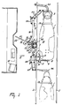
- Figure 1 shows in a plan view a cow 1, stationed in the milking parlour.
- the milking parlour is bounded on both sides by guide rails 2, between which the animal can walk forwards until its head reaches the manger 3; the animal 1 will stop then.
- a mechanism 5 is provided for this purpose, which comprises a swivel arm 6 which is capable of hinging around a substantially horizontal pin 7, and whose other end is provided with a rod like mechanical sensor 8 fastened to the swivel arm at a substantially square angle.
- the rod 8 has a movable mechanical sensor 9 which can be moved along the rod 8 until it comes to bear on the animal (as is shown in Figure 1).
- the rod 8 is provided with a toothed rack 10, whilst sensor 9 includes an electric motor 11.
- the sensor 9 is moved along the rod 8 until the sensor touches the animal 1, means, not further shown, being present for switching off the electric motor 11 when sensor 9 experiences a slight resistance during its travel.
- the lateral position of the animal 1 can be determined.
- the rod 8 is rotated around a hinge pin 7, so that it bears against the posterior of the animal 1.
- the angular position then obtained for the swivel arm 6 determines the position of the cow in the forward direction.
- the computer 12 which is shown schematically in Figure 1. If it is furthermore known which cow is in the milking parlour, the computer can determine with an adequate degree of accuracy in what way the milking cluster 4 is to be attached.
- the animal carries identification means which, in the embodiments shown in the Figures 1 and 2, are constituted by an information carrier 14 fastened to a collar 13.
- This information carrier 14 is, for example, a small transmitter, whose signals can be picked up by a sensor connected to the computer and present in the milking parlour.
- the milking cluster 4 can be moved to the relevant position with the aid of the support 15.
- a frame 16 is provided which is fastened to the floor by means of legs 17.
- the support 15 is fastened capable of hinging, around the substantially vertical pin 18 to the frame 16; rotation around hinge pin 18 is effected by the adjusting device 19, for example a pneumatic or hydraulic cylinder unit.
- the support 15 includes a rod 21, having a toothed rack 22, with the aid of which the rod 21 can be moved in its longitudinal direction relative to the frame.
- the milking cluster 4 can be adjusted to any desired position in a horizontal plane. Since the support 15 can also swivel around a substantially horizontal axis relative to the frame, adjustment of the milking cluster 4 in the vertical direction can be achieved. This last mode of adjustment is shown in detail in Figure 3.
- FIG. 3 shows the milking cluster 4 having four teat cups 23 which together are supported in the support 15.
- the hollow bar of the frame 16 is shown in a cross-sectional view.
- a support 24 is provided on this hollow bar 16, which support is capable of swiveling relative to the bar around the hinge pin 18, using an actuating device 19, which is only partly shown.
- the support 24 is connected to the support 15 by means of a substantially horizontal hinge pin 25, around which portion 26 of the support is swivable.
- This swivelling action is controlled by actuating device 27, which comprises, for example, a pneumatic or hydraulic cylinder and is connected by means of ball joints 28 to the frame 16 and also to portion 26 of the support.
- the portion 26 of the support 15 can consequently rotate around both the vertical pin 18 and the horizontal pin 25.
- Figure 3 shows the electric motor 29, for example a stepper motor, which has on its axle a pinion 30 which cooperates with the toothed rack 22 so as to move rod 21 in its longitudinal direction, causing the milking cluster 31 provided at the end of the rod 21 to be moved to under the animal.
- the milking cluster holder 31 is connected, capable of hinging around shaft 32, to the rod 21 through a fork 33, as a result of which the milking cluster holder remains at all times in a horizontal position.
- the milking cluster can be adjusted to any desired position by means of an appropriate control of the adjusting devices 19 and 27, and the electric motor 29.
- Figure 3 also shows the manner in which the teat cups 23 may be arranged in the milking cluster holder 31.
- the wider portion of the flaring teat cup 23 is supported in a recess of the milking cluster holder 31, so that the teat cups can be freely move up, thus getting free from the milking cluster holder 31.
- Releasing the cups from the milking cluster holder can be effected after the milking cluster has been attached to the udder and the vacuum has been generated, causing the teat cups to remain attached to the teats, by moving the milking cluster holder downwards.
- the tubes 39 connecting the teat cups 23 to the milking machine are adequately flexible, the teat cups 23, after having been lifted from the milking cluster holder 31, have a certain degree of freedom to follow the motions of the animal. After milking has been terminated the vacuum is terminated, which causes the teat cups 23 to fall automatically back into said recesses in the milking cluster holder.
- a computer-controlled quantity of fodder for example concentrate
- the manger 3 can be moved to a position outside the milking parlour.
- the animal can leave the milking parlour in the forward direction after milking has been terminated.
- the next animal is already present-between the guide rails 2, but at some distance from the milking parlour.
- This animal can move up to the milking parlour, lured there by the manger 3, after the mechanism 5 has been moved upwards around a hinge pin 7, and the partition 36 which is connected through the rod system 37 to the frame 16 has been moved to a position outside the guide rails by means of actuating device 38.
Description
- The invention relates to a device for automatically milking animals, as described in the preamble of
claim 1. Such a device is known from US-A 4,010,714. - In said US-document, an animal is forced into a fixed position in the milking parlour by means of supporting plates with air bags and further support members at the front side of the milking parlour. In that position, teat cups must be attached to the teats of the animal. In such a fixed position, the animals will not feel comfortable.
- The invention has for its object to provide a device for automatically milking animals, such as cows, in which the position of the animal can be determined in a manner that the milking cluster can be attached efficiently, while the animal feels comfortable.
- According to the invention this is achieved by the features as defined in
claim 1. - Such mechanical sensors may be of a very light construction, so that it is hardly noticeable to the animal, the position of the mechanical sensors then being recorded and constituting an information on the basis of which the position of the animal can be determined.
- According to a further characteristic of the invention, the mechanical sensors may be movable along the posterior of the animal, more specifically above the hind legs of the animal, for example on the most rearward portion of the animal. In this situation, according to a further characteristic of the invention, the mechanical sensors may be connected to a swivelling member which is capable of hinging around a substantially horizontal axis above the animal, the hinge axis being substantially transversely of the milking parlour. Then, according to a further characteristic of the invention, the mechanical sensors may rest against the posterior of the animal by its own weight, the angular position of the swiveling member then being a measure of the position of the animal. Additionally, according to a further characteristic of the invention, the mechanical sensors comprise rods, a first one of which can bear on the animal's side at the same level as the second one. In this situation, according to a further characteristic of the invention, the first rod can be fastened to the swiveling member and be at a substantially square angle to the second rod. By measuring the position of the animal's posterior in both the longitudinal direction and the lateral direction, sufficient information can be obtained to determine, depending on the animal (that is to say, using the data of the relevant animal, stored in the computer), the position of the udder.
- The position and the place of each individual teat cup of the milking cluster may be adjustable depending on the position of the teats of a specific animal. This position may however alter, depending on a number of factors or depending on the age of the animal. To obviate this, means are provided which, during the milking operations, record the positions of the teat cups and store them as data, with the object of using these data during a subsequent milking operation of the same animal in such a way that before the milking cluster is placed on the udder, the position of the teat cups is adjusted in accordance with the previously recorded position during milking of the same animal. Thus also gradual changes in the position of the teats can be observed, whereafter the adjustment of the milking cluster for the relevant animal can be adapted thereto.
- In the computer, which controls the means for positioning the milking cluster, a plurality of data of the animal to be milked may be stored. This data may contain the configuration (relative location and/or position) of the teats the position of the teats relative to a reference point, preferably one of the teats, the horizontal distance between the rear of the animal and a reference point near the udder, and/or the distance between a different detection point and the reference point, and the horizontally measured distance between the side of the animal and a reference point at the udder. From this data the computer can derive the relevant control signals for the means for positioning the milking cluster. Furthermore the computer can store the time elapsed between milking operations of the same animal. Such an information may be important in connection with the quantity of fodder the animals is fed during milking, but also in connection with the expected quantity of milk and the degree to which the udder is filled. This last item may affect the position and the location of the teats, so that these data can be taken into account in the determination of the actions to be performed for attaching the milking cluster.
- By way of further illustration of the invention some embodiments of the automatic milking device will be described with reference to the accompanying drawing.
- Figure 1 is a schematic plan view of the milking device;
- Figure 2 is a side view of the milking device shown in Figure 1;
- Figure 3 illustrates the milking cluster with support.
-
- In these Figures corresponding components are given the same reference numerals.
- Figure 1 shows in a plan view a
cow 1, stationed in the milking parlour. The milking parlour is bounded on both sides byguide rails 2, between which the animal can walk forwards until its head reaches themanger 3; theanimal 1 will stop then. To enable correct positioning of the milking cluster 4 the position of the animal must be determined. A mechanism 5 is provided for this purpose, which comprises a swivel arm 6 which is capable of hinging around a substantially horizontal pin 7, and whose other end is provided with a rod likemechanical sensor 8 fastened to the swivel arm at a substantially square angle. Therod 8 has a movable mechanical sensor 9 which can be moved along therod 8 until it comes to bear on the animal (as is shown in Figure 1). In the embodiments shown in the Figures 1 and 2, therod 8 is provided with a toothed rack 10, whilst sensor 9 includes an electric motor 11. Thus, the sensor 9 is moved along therod 8 until the sensor touches theanimal 1, means, not further shown, being present for switching off the electric motor 11 when sensor 9 experiences a slight resistance during its travel. It will be obvious that using the sensor 9 the lateral position of theanimal 1 can be determined. Prior to this determination, therod 8 is rotated around a hinge pin 7, so that it bears against the posterior of theanimal 1. The angular position then obtained for the swivel arm 6 determines the position of the cow in the forward direction. These data are conveyed to thecomputer 12, which is shown schematically in Figure 1. If it is furthermore known which cow is in the milking parlour, the computer can determine with an adequate degree of accuracy in what way the milking cluster 4 is to be attached. - To determine which animal is present in the milking parlour the animal carries identification means which, in the embodiments shown in the Figures 1 and 2, are constituted by an
information carrier 14 fastened to acollar 13. Thisinformation carrier 14 is, for example, a small transmitter, whose signals can be picked up by a sensor connected to the computer and present in the milking parlour. - After it has been determined where the milking cluster 4 is to be connected, the milking cluster 4 can be moved to the relevant position with the aid of the
support 15. For that purpose aframe 16 is provided which is fastened to the floor by means oflegs 17. Thesupport 15 is fastened capable of hinging, around the substantiallyvertical pin 18 to theframe 16; rotation aroundhinge pin 18 is effected by the adjustingdevice 19, for example a pneumatic or hydraulic cylinder unit. Thesupport 15 includes arod 21, having atoothed rack 22, with the aid of which therod 21 can be moved in its longitudinal direction relative to the frame. Using these two displacement modes, swivelling around thevertical pin 18 and longitudinal movement of therod 21, the milking cluster 4 can be adjusted to any desired position in a horizontal plane. Since thesupport 15 can also swivel around a substantially horizontal axis relative to the frame, adjustment of the milking cluster 4 in the vertical direction can be achieved. This last mode of adjustment is shown in detail in Figure 3. - Figure 3 shows the milking cluster 4 having four
teat cups 23 which together are supported in thesupport 15. The hollow bar of theframe 16 is shown in a cross-sectional view. Asupport 24 is provided on thishollow bar 16, which support is capable of swiveling relative to the bar around thehinge pin 18, using an actuatingdevice 19, which is only partly shown. Thesupport 24 is connected to thesupport 15 by means of a substantiallyhorizontal hinge pin 25, around whichportion 26 of the support is swivable. This swivelling action is controlled by actuatingdevice 27, which comprises, for example, a pneumatic or hydraulic cylinder and is connected by means ofball joints 28 to theframe 16 and also toportion 26 of the support. Theportion 26 of thesupport 15 can consequently rotate around both thevertical pin 18 and thehorizontal pin 25. - Additionally, Figure 3 shows the
electric motor 29, for example a stepper motor, which has on its axle apinion 30 which cooperates with thetoothed rack 22 so as to moverod 21 in its longitudinal direction, causing themilking cluster 31 provided at the end of therod 21 to be moved to under the animal. As can be seen from Figures 1 and 3, themilking cluster holder 31 is connected, capable of hinging aroundshaft 32, to therod 21 through afork 33, as a result of which the milking cluster holder remains at all times in a horizontal position. Using the described construction, the milking cluster can be adjusted to any desired position by means of an appropriate control of the adjustingdevices electric motor 29. - Figure 3 also shows the manner in which the
teat cups 23 may be arranged in themilking cluster holder 31. The wider portion of theflaring teat cup 23 is supported in a recess of themilking cluster holder 31, so that the teat cups can be freely move up, thus getting free from themilking cluster holder 31. Releasing the cups from the milking cluster holder can be effected after the milking cluster has been attached to the udder and the vacuum has been generated, causing the teat cups to remain attached to the teats, by moving the milking cluster holder downwards. As thetubes 39 connecting theteat cups 23 to the milking machine are adequately flexible, theteat cups 23, after having been lifted from themilking cluster holder 31, have a certain degree of freedom to follow the motions of the animal. After milking has been terminated the vacuum is terminated, which causes theteat cups 23 to fall automatically back into said recesses in the milking cluster holder. - With the object of luring the
animal 1 to the milking parlour and/or during milking, a computer-controlled quantity of fodder, for example concentrate, can be conveyed throughpipe 50 to themanger 3. By means of arod system 34 and an adjustingdevice 35, themanger 3 can be moved to a position outside the milking parlour. Thus, the animal can leave the milking parlour in the forward direction after milking has been terminated. - As is shown in Figures 1 and 2, the next animal is already present-between the
guide rails 2, but at some distance from the milking parlour. This animal can move up to the milking parlour, lured there by themanger 3, after the mechanism 5 has been moved upwards around a hinge pin 7, and thepartition 36 which is connected through therod system 37 to theframe 16 has been moved to a position outside the guide rails by means of actuatingdevice 38.
Claims (5)
- Device for automatically milking animals, comprising a milking parlour, which is bounded on at least two sides by guide means (2), between which guide means (2) the animal can be positioned, the device further comprising means for positioning and attaching a milking cluster to the udder of the animal, characterized in that the device further comprises detection means which are suitable for determining the position of the posterior of the animal in both the longitudinal and lateral direction relative to the milking parlour, the detection means comprising two mechanical sensors (8, 9), which are constantly brought into contact with the animal body at least during the phase of the milking process in which the milking cluster has to be attached to the udder in order to determine the position of said posterior of the animal, a computer (12) is provided to which computer (12) first data indicating the position of said posterior of the animal relative to the milking parlour are supplied by the detection means, the device further comprising an animal identification system which supplies second data to the computer (12), the said second data indicate the identity of the animal present in the milking parlour, while furthermore third data indicating the position of the udder of the animal relative to the position of said posterior of the animal are stored in the computer (12) and the computer (12) controls the means for positioning and attaching the milking cluster in response to the first, second and third data.
- Device as claimed in claim 1, characterized in that the mechanical sensors (8, 9) are movable along the posterior of the animal, more specifically above the hind legs of the animal, for example on the most rearward position of the animal.
- Device as claimed in claim 2, characterized in that the mechanical sensors (8, 9) are connected to a swivelling member (6) which is capable of hinging around a substantially horizontal axis (7) above the animal.
- Device as claimed in claim 3, characterized in that the mechanical sensors (8, 9) rest against the posterior of the animal by its own weight, the angular position of the swivelling member (6) then being a measure of the position of the animal.
- Device as claimed in claim 3 or 4, characterized in that the mechanical sensors comprise rods (8, 9), a first one (9) of which can bear on the animal's side at the same level as the second one (8), which first rod (9) can be fastened to the swivelling member (6) and be at a substantially square angle to the second rod (8).
Priority Applications (2)
| Application Number | Priority Date | Filing Date | Title |
|---|---|---|---|
| EP89101861A EP0320496B2 (en) | 1985-01-16 | 1986-01-15 | Device for automatically milking animals |
| AT89101861T ATE83122T1 (en) | 1985-01-16 | 1986-01-15 | DEVICE FOR AUTOMATIC MILKING OF ANIMALS. |
Applications Claiming Priority (4)
| Application Number | Priority Date | Filing Date | Title |
|---|---|---|---|
| NL8500088 | 1985-01-16 | ||
| NL8500088A NL8500088A (en) | 1985-01-16 | 1985-01-16 | DEVICE FOR AUTOMATIC MILKING OF AN ANIMAL. |
| EP86200063A EP0188303B1 (en) | 1985-01-16 | 1986-01-15 | Implement for automatically milking an animal |
| EP89101861A EP0320496B2 (en) | 1985-01-16 | 1986-01-15 | Device for automatically milking animals |
Related Parent Applications (2)
| Application Number | Title | Priority Date | Filing Date |
|---|---|---|---|
| EP86200063A Division EP0188303B1 (en) | 1985-01-16 | 1986-01-15 | Implement for automatically milking an animal |
| EP86200063.5 Division | 1986-01-15 |
Publications (4)
| Publication Number | Publication Date |
|---|---|
| EP0320496A2 EP0320496A2 (en) | 1989-06-14 |
| EP0320496A3 EP0320496A3 (en) | 1989-10-04 |
| EP0320496B1 EP0320496B1 (en) | 1992-12-09 |
| EP0320496B2 true EP0320496B2 (en) | 1999-09-15 |
Family
ID=26102927
Family Applications (2)
| Application Number | Title | Priority Date | Filing Date |
|---|---|---|---|
| EP89101862A Expired - Lifetime EP0319523B2 (en) | 1985-01-16 | 1986-01-15 | Device for automatically milking an animal |
| EP89101861A Expired - Lifetime EP0320496B2 (en) | 1985-01-16 | 1986-01-15 | Device for automatically milking animals |
Family Applications Before (1)
| Application Number | Title | Priority Date | Filing Date |
|---|---|---|---|
| EP89101862A Expired - Lifetime EP0319523B2 (en) | 1985-01-16 | 1986-01-15 | Device for automatically milking an animal |
Country Status (1)
| Country | Link |
|---|---|
| EP (2) | EP0319523B2 (en) |
Families Citing this family (31)
| Publication number | Priority date | Publication date | Assignee | Title |
|---|---|---|---|---|
| DE3931769C2 (en) * | 1989-09-25 | 2001-10-11 | Westfalia Landtechnik Gmbh | Machine for milking animals |
| NL9100992A (en) * | 1991-06-10 | 1993-01-04 | Lely Nv C Van Der | DEVICE FOR MILKING ANIMALS. |
| GB9113405D0 (en) * | 1991-06-20 | 1991-08-07 | Silsoe Research Inst | Automatic milking |
| DE69223894T3 (en) * | 1991-10-04 | 2005-01-20 | Maasland N.V. | Method for cleaning milking cups and device for milking animals using this method |
| NL9200258A (en) * | 1991-10-04 | 1993-05-03 | Lely Nv C Van Der | METHOD FOR CLEANING MILK BEAKERS AND / OR AFTER-TREATMENT OF THE WEANING OF A MILKED ANIMAL, ANIMAL MILKING APPARATUS FOR USING THIS METHOD (S), AND A RINSE TOOL APPLIED IN SUCH AN APPARATUS. |
| NL9201128A (en) * | 1992-06-25 | 1994-01-17 | Lely Nv C Van Der | APPARATUS FOR AUTOMATIC MILKING OF ANIMALS, SUCH AS COWS. |
| NL9300443A (en) * | 1993-03-11 | 1994-10-03 | Prolion Bv | Method and device for monitoring animal functions. |
| NL9300578A (en) * | 1993-04-01 | 1994-11-01 | Texas Industries Inc | Device for automatic milking of animals. |
| NL9301377A (en) * | 1993-08-09 | 1995-03-01 | Lely Nv C Van Der | Device for automatic milking of animals. |
| NL9301414A (en) * | 1993-08-16 | 1995-03-16 | Lely Nv C Van Der | Device for automatic milking of animals. |
| NL9500362A (en) * | 1994-04-14 | 1995-11-01 | Maasland Nv | Method for automatic milking of animals and device in which this method can be applied. |
| SE9701310D0 (en) † | 1997-04-11 | 1997-04-11 | Alfa Laval Agri Ab | A teatcup magazine, a milking arrangement, and a method of handling a teatcup |
| NL1009631C2 (en) * | 1998-07-13 | 2000-01-17 | Gascoigne Melotte Bv | Automated milking parlor for dairy cattle uses optical sensors to detect positions of teats and attach suction pipes, requires minimal human labor |
| NL1015671C2 (en) * | 2000-07-10 | 2002-01-11 | Lely Entpr Ag | Device for automatic milking of animals. |
| US7290497B2 (en) * | 2001-09-21 | 2007-11-06 | Westfaliasurge, Inc. | Milking device provided with cleansing means |
| NL1017984C2 (en) * | 2001-05-02 | 2002-11-05 | Idento Electronics Bv | Milking device. |
| US10874084B2 (en) | 2004-06-12 | 2020-12-29 | Gea Farm Technologies, Inc. | Safety valve for a dairy system component |
| US8033247B2 (en) | 2004-06-12 | 2011-10-11 | Gea Farm Technologies, Inc. | Automatic dairy animal milker unit backflusher and teat dip applicator system and method |
| US8342125B2 (en) | 2004-06-12 | 2013-01-01 | Gea Farm Technologies, Inc. | Safety valve for an automatic dairy animal milker unit backflusher and teat dip applicator |
| US8025029B2 (en) | 2004-06-12 | 2011-09-27 | Gea Farm Technologies, Inc. | Automatic dairy animal milker unit backflusher and teat dip applicator system and method |
| US8117989B2 (en) | 2008-06-27 | 2012-02-21 | Gea Farm Technologies, Inc. | Milk tube dome with flow controller |
| EP2355652B2 (en) | 2008-11-10 | 2021-03-17 | GEA Farm Technologies GmbH | Method and device for automatically bringing a fluid into contact with the teats of an animal |
| US8770146B2 (en) | 2009-09-04 | 2014-07-08 | Gea Farm Technologies, Inc. | Methods and apparatus for applying teat dip to a dairy animal |
| US11723341B2 (en) | 2009-09-04 | 2023-08-15 | Gea Farm Technologies, Inc. | Safety valve for an automated milker unit backflushing and teat dip applicator system |
| US8662012B2 (en) | 2010-01-12 | 2014-03-04 | Delaval Holdings Ab | Positioning system for at least one flexible tubular element connected to a cup-shaped member |
| US20120097107A1 (en) | 2010-02-22 | 2012-04-26 | Gea Farm Technologies, Inc. | Dairy animal milking preparation system and methods |
| RU2676917C2 (en) | 2010-02-22 | 2019-01-11 | Геа Фарм Технолоджис, Инк. | Apparatus for milking and milk collection with milk line protection |
| US9526224B2 (en) | 2013-12-20 | 2016-12-27 | Gea Farm Technologies Gmbh | Safety valve device |
| DE102013114595A1 (en) | 2013-12-20 | 2015-06-25 | Gea Farm Technologies Gmbh | safety valve |
| DE102016108300A1 (en) | 2016-05-04 | 2017-11-09 | Gea Farm Technologies Gmbh | safety valve |
| US11617343B2 (en) | 2017-11-03 | 2023-04-04 | Gea Farm Technologies Gmbh | Automated teat dip fluid manifold |
Family Cites Families (4)
| Publication number | Priority date | Publication date | Assignee | Title |
|---|---|---|---|---|
| US3763828A (en) * | 1971-12-10 | 1973-10-09 | Dari Spray Products Inc | Cow treating device |
| US4010714A (en) * | 1974-03-08 | 1977-03-08 | Director, National Institute Of Animal Industry | System for managing milking-cows in stanchion stool |
| GB2007486B (en) * | 1977-11-12 | 1982-03-03 | Akerman D E | Milking method and apparatus |
| SE430559B (en) * | 1982-04-08 | 1983-11-28 | Alfa Laval Ab | SET FOR MILK AND DEVICE HERE |
-
1986
- 1986-01-15 EP EP89101862A patent/EP0319523B2/en not_active Expired - Lifetime
- 1986-01-15 EP EP89101861A patent/EP0320496B2/en not_active Expired - Lifetime
Also Published As
| Publication number | Publication date |
|---|---|
| EP0319523B1 (en) | 1993-03-10 |
| EP0320496A3 (en) | 1989-10-04 |
| EP0319523A3 (en) | 1989-10-11 |
| EP0319523B2 (en) | 1995-10-25 |
| EP0320496A2 (en) | 1989-06-14 |
| EP0319523A2 (en) | 1989-06-07 |
| EP0320496B1 (en) | 1992-12-09 |
Similar Documents
| Publication | Publication Date | Title |
|---|---|---|
| EP0320496B2 (en) | Device for automatically milking animals | |
| EP0188303B1 (en) | Implement for automatically milking an animal | |
| EP0736246B1 (en) | A method of positioning means for automatically milking animals, such as cows, as well as an implement for applying same | |
| EP0194729B1 (en) | Implement for milking animals | |
| EP0480541B1 (en) | A method of automatically milking animals and an implement for performing same | |
| EP0824857B2 (en) | A method of automatically connecting teat cups to the teats of an animal to be milked | |
| US6244215B1 (en) | Device and method for milking animals | |
| US5909716A (en) | Apparatus for and a method of milking animals | |
| US20120143375A1 (en) | Milking robot and method for teat cup attachment | |
| CA2007077A1 (en) | Milking | |
| US6116188A (en) | Method of milking animals | |
| EP1120032B1 (en) | A construction for automatically milking animals | |
| EP0880888B1 (en) | An implement for automatically milking animals | |
| EP0990387B1 (en) | An implement for milking animals | |
| EP0692187B1 (en) | An implement for milking animals | |
| WO2001030134A1 (en) | Means for improved milking |
Legal Events
| Date | Code | Title | Description |
|---|---|---|---|
| PUAI | Public reference made under article 153(3) epc to a published international application that has entered the european phase |
Free format text: ORIGINAL CODE: 0009012 |
|
| AC | Divisional application: reference to earlier application |
Ref document number: 188303 Country of ref document: EP |
|
| AK | Designated contracting states |
Kind code of ref document: A2 Designated state(s): AT BE CH DE FR GB IT LI NL SE |
|
| PUAL | Search report despatched |
Free format text: ORIGINAL CODE: 0009013 |
|
| AK | Designated contracting states |
Kind code of ref document: A3 Designated state(s): AT BE CH DE FR GB IT LI NL SE |
|
| 17P | Request for examination filed |
Effective date: 19900314 |
|
| 17Q | First examination report despatched |
Effective date: 19910220 |
|
| GRAA | (expected) grant |
Free format text: ORIGINAL CODE: 0009210 |
|
| AC | Divisional application: reference to earlier application |
Ref document number: 188303 Country of ref document: EP |
|
| AK | Designated contracting states |
Kind code of ref document: B1 Designated state(s): AT BE CH DE FR GB IT LI NL SE |
|
| REF | Corresponds to: |
Ref document number: 83122 Country of ref document: AT Date of ref document: 19921215 Kind code of ref document: T |
|
| REF | Corresponds to: |
Ref document number: 3687273 Country of ref document: DE Date of ref document: 19930121 |
|
| ITF | It: translation for a ep patent filed |
Owner name: STUDIO ING. ALFREDO RAIMONDI |
|
| ET | Fr: translation filed | ||
| PLBI | Opposition filed |
Free format text: ORIGINAL CODE: 0009260 |
|
| PLAB | Opposition data, opponent's data or that of the opponent's representative modified |
Free format text: ORIGINAL CODE: 0009299OPPO |
|
| PLBI | Opposition filed |
Free format text: ORIGINAL CODE: 0009260 |
|
| 26 | Opposition filed |
Opponent name: ALFA LAVAL AGRI AB Effective date: 19930902 |
|
| 26 | Opposition filed |
Opponent name: PROLION B.V. Effective date: 19930908 Opponent name: ALFA LAVAL AGRI AB Effective date: 19930831 |
|
| R26 | Opposition filed (corrected) |
Opponent name: ALFA LAVAL AGRI AB Effective date: 19930831 |
|
| NLR1 | Nl: opposition has been filed with the epo |
Opponent name: ALFA LAVAL AGRI AB |
|
| NLR1 | Nl: opposition has been filed with the epo |
Opponent name: PROLION B.V. |
|
| NLXE | Nl: other communications concerning ep-patents (part 3 heading xe) |
Free format text: PAT.BUL.01/94 CORR.:"930831" |
|
| EAL | Se: european patent in force in sweden |
Ref document number: 89101861.6 |
|
| PLAW | Interlocutory decision in opposition |
Free format text: ORIGINAL CODE: EPIDOS IDOP |
|
| APAE | Appeal reference modified |
Free format text: ORIGINAL CODE: EPIDOS REFNO |
|
| APAC | Appeal dossier modified |
Free format text: ORIGINAL CODE: EPIDOS NOAPO |
|
| APAC | Appeal dossier modified |
Free format text: ORIGINAL CODE: EPIDOS NOAPO |
|
| RAP2 | Party data changed (patent owner data changed or rights of a patent transferred) |
Owner name: MAASLAND N.V. |
|
| NLT2 | Nl: modifications (of names), taken from the european patent patent bulletin |
Owner name: MAASLAND N.V. |
|
| NLS | Nl: assignments of ep-patents |
Owner name: MAASLAND N.V. |
|
| REG | Reference to a national code |
Ref country code: CH Ref legal event code: PUE Owner name: C. VAN DER LELY N.V. TRANSFER- MAASLAND N.V. |
|
| APAC | Appeal dossier modified |
Free format text: ORIGINAL CODE: EPIDOS NOAPO |
|
| PLAW | Interlocutory decision in opposition |
Free format text: ORIGINAL CODE: EPIDOS IDOP |
|
| PUAH | Patent maintained in amended form |
Free format text: ORIGINAL CODE: 0009272 |
|
| STAA | Information on the status of an ep patent application or granted ep patent |
Free format text: STATUS: PATENT MAINTAINED AS AMENDED |
|
| 27A | Patent maintained in amended form |
Effective date: 19990915 |
|
| AK | Designated contracting states |
Kind code of ref document: B2 Designated state(s): AT BE CH DE FR GB IT LI NL SE |
|
| RIC2 | Information provided on ipc code assigned after grant |
Free format text: 6A 01J 7/00 A, 6A 01K 1/12 B, 6A 01J 5/017 B |
|
| REG | Reference to a national code |
Ref country code: CH Ref legal event code: AEN Free format text: AUFRECHTERHALTUNG DES PATENTES IN GEAENDERTER FORM |
|
| ITF | It: translation for a ep patent filed |
Owner name: STUDIO ING. ALFREDO RAIMONDI |
|
| ET3 | Fr: translation filed ** decision concerning opposition | ||
| NLR3 | Nl: receipt of modified translations in the netherlands language after an opposition procedure | ||
| REG | Reference to a national code |
Ref country code: GB Ref legal event code: IF02 |
|
| PGFP | Annual fee paid to national office [announced via postgrant information from national office to epo] |
Ref country code: SE Payment date: 20021219 Year of fee payment: 18 Ref country code: AT Payment date: 20021219 Year of fee payment: 18 |
|
| PGFP | Annual fee paid to national office [announced via postgrant information from national office to epo] |
Ref country code: NL Payment date: 20021223 Year of fee payment: 18 Ref country code: CH Payment date: 20021223 Year of fee payment: 18 |
|
| PGFP | Annual fee paid to national office [announced via postgrant information from national office to epo] |
Ref country code: GB Payment date: 20030108 Year of fee payment: 18 |
|
| PGFP | Annual fee paid to national office [announced via postgrant information from national office to epo] |
Ref country code: BE Payment date: 20030114 Year of fee payment: 18 |
|
| PGFP | Annual fee paid to national office [announced via postgrant information from national office to epo] |
Ref country code: DE Payment date: 20030131 Year of fee payment: 18 |
|
| PG25 | Lapsed in a contracting state [announced via postgrant information from national office to epo] |
Ref country code: GB Free format text: LAPSE BECAUSE OF NON-PAYMENT OF DUE FEES Effective date: 20040115 Ref country code: AT Free format text: LAPSE BECAUSE OF NON-PAYMENT OF DUE FEES Effective date: 20040115 |
|
| PG25 | Lapsed in a contracting state [announced via postgrant information from national office to epo] |
Ref country code: SE Free format text: LAPSE BECAUSE OF NON-PAYMENT OF DUE FEES Effective date: 20040116 |
|
| PGFP | Annual fee paid to national office [announced via postgrant information from national office to epo] |
Ref country code: FR Payment date: 20040122 Year of fee payment: 19 |
|
| PG25 | Lapsed in a contracting state [announced via postgrant information from national office to epo] |
Ref country code: LI Free format text: LAPSE BECAUSE OF NON-PAYMENT OF DUE FEES Effective date: 20040131 Ref country code: CH Free format text: LAPSE BECAUSE OF NON-PAYMENT OF DUE FEES Effective date: 20040131 Ref country code: BE Free format text: LAPSE BECAUSE OF NON-PAYMENT OF DUE FEES Effective date: 20040131 |
|
| BERE | Be: lapsed |
Owner name: *MAASLAND N.V. Effective date: 20040131 |
|
| PG25 | Lapsed in a contracting state [announced via postgrant information from national office to epo] |
Ref country code: NL Free format text: LAPSE BECAUSE OF NON-PAYMENT OF DUE FEES Effective date: 20040801 |
|
| PG25 | Lapsed in a contracting state [announced via postgrant information from national office to epo] |
Ref country code: DE Free format text: LAPSE BECAUSE OF NON-PAYMENT OF DUE FEES Effective date: 20040803 |
|
| EUG | Se: european patent has lapsed | ||
| GBPC | Gb: european patent ceased through non-payment of renewal fee |
Effective date: 20040115 |
|
| REG | Reference to a national code |
Ref country code: CH Ref legal event code: PL |
|
| NLV4 | Nl: lapsed or anulled due to non-payment of the annual fee |
Effective date: 20040801 |
|
| PG25 | Lapsed in a contracting state [announced via postgrant information from national office to epo] |
Ref country code: IT Free format text: LAPSE BECAUSE OF NON-PAYMENT OF DUE FEES Effective date: 20050115 |
|
| PG25 | Lapsed in a contracting state [announced via postgrant information from national office to epo] |
Ref country code: FR Free format text: LAPSE BECAUSE OF NON-PAYMENT OF DUE FEES Effective date: 20050930 |
|
| APAH | Appeal reference modified |
Free format text: ORIGINAL CODE: EPIDOSCREFNO |
|
| REG | Reference to a national code |
Ref country code: FR Ref legal event code: ST |