EP0638232B1 - A construction for automatically milking animals - Google Patents
A construction for automatically milking animals Download PDFInfo
- Publication number
- EP0638232B1 EP0638232B1 EP19940202259 EP94202259A EP0638232B1 EP 0638232 B1 EP0638232 B1 EP 0638232B1 EP 19940202259 EP19940202259 EP 19940202259 EP 94202259 A EP94202259 A EP 94202259A EP 0638232 B1 EP0638232 B1 EP 0638232B1
- Authority
- EP
- European Patent Office
- Prior art keywords
- construction
- detection member
- animal
- teats
- milking box
- Prior art date
- Legal status (The legal status is an assumption and is not a legal conclusion. Google has not performed a legal analysis and makes no representation as to the accuracy of the status listed.)
- Expired - Lifetime
Links
Images


Classifications
-
- A—HUMAN NECESSITIES
- A01—AGRICULTURE; FORESTRY; ANIMAL HUSBANDRY; HUNTING; TRAPPING; FISHING
- A01J—MANUFACTURE OF DAIRY PRODUCTS
- A01J5/00—Milking machines or devices
- A01J5/017—Automatic attaching or detaching of clusters
- A01J5/0175—Attaching of clusters
Definitions
- the separate motional ability of the detection member and the robot head has as an advantage that the detection member can be introduced into the milking box in one direction and that the robot head can be moved into the milking box from a different direction.
- the detection member may have been moved to a position near the rear side of the udder passing between the hind legs, as well as near the side of the udder from the side wall of the milking box, whilst in both these cases the robot head can then be guided rearwardly from the leading side, after having been pivoted to under the animal.
- "From the rear side of the milking box” means that the detection member can be guided to the udder whilst passing between the hind legs as well as passing along one of the hind legs, to the side of the udder.
- the box 1 is therefore also provided with means for selecting the animals, whilst furthermore the opportunity can be used to clean and optionally massage the udder of the animal to stimulate the milk production, when by means of the animal identification system and the data in the file of the relevant animal in the memory of the computer system it has been decided that the animal may be milked, whilst in addition concentrate can be supplied to the animal in the box 1.
- the box 2 is equipped as a milking box, into which an animal is admitted from box 1 for the purpose of being milked, whilst additional concentrate can be fed to the animal if desired.
- stimulating means may be placed all over the construction, more specifically in the lying boxes and in the feeding stations, for stimulating the animal to go to the milking box.
- These stimulating means can, for example, produce sound or light signals or, more in particular, the animals in the lying boxes and in the feeding stations can be given electric shocks, which contribute to forcing the animals to go from the lying box or feeding station to the milking boxes 1 and 2 through the shed.
- a suitable shed lay-out more specifically such a shed lay-out in which the animals must follow a fixed path through the shed to the milking box, will definitely contribute thereto.
- Figures 2 and 3 are a plan view and a side view, respectively, of only the milking box 2.
- a milking robot 19 is present, which includes a robot arm construction 20, at the end of which a robot head 21 is disposed which serves as a carrier for four teat cups 22.
- the milking robot 19 includes a carrier structure 23 for a detection member 24.
- the robot arm construction 20 carrying the robot head 21 and the teat cups 22 is independently movable with respect to the carrier structure 23 with the detection member 24.
- the detection member 24 is designed as a laser which is pivotal about an upwardly directed shaft and produces a very narrow scanning beam, which is moved from a short distance over the teats of the animal, an extremely accurate positional determination of the teats is made possible.
- the detection member 24 can be adjusted to the position shown by moving the detection member to a central position between the two longitudinal sides and by moving it thereafter to a position which is determined from the computer system on the basis of the data stored in the file of the animal about the position of the teats.
- the motion of the detection member 24 is performed totally independently of the robot arm carrier structure 20 of the teat cups 22 and is therefore not obstructed thereby in any way.
- Figure 4 shows an alternative embodiment of the carrier structure 23 for the detection member 24.
- the detection member 24 is then directly disposed at the end of the carrier 35.
- the carrier structure 23 and, more in particular the carrier 35 is in a more advanced position, it will be necessary for the robot arm structure 20 to be adjusted to a more advanced position so as to be able to pivot to under the animal without any obstruction by the carrier structure 23.
- the robot head 21 can be moved rearwardly towards the udder.
- milking box the place in which the animals are present during milking is designated as a milking box. It will be obvious that this milking box may be of any conceivable design; it may also form part of the shed.
- the invention is therefore not limited to the construction shown here and is also not limited to the embodiments described sofar, but also relates to all kinds of modifications thereof, of course in sofar they are within the scope of the accompanying claims.
Description
- The present invention relates to a construction or a similar arrangement according to the preamble of
claim 1. In EP-A-0 229 682, the detection member is attached to the robot head, which serves as a carrier for one or a number of teat cups, and interferes with an accurate determination of the position of the teats by the detection member. In order to facilitate this positional determination and to perform it accurately, and to create a more flexible system, the construction of the type as described in the preamble is, according to the invention, characterized in that the detection member and the robot head are movable independently of each other. Thereby, the detection member can be moved very closely to the teats, which achieves a very high accuracy in the determination of the position of the teats. As in the prior art construction usually all four teat cups as well as the detection member are disposed on the robot head, the detection movements are limited. By disposing the detection member separately, a higher flexibility in the design is obtained. The separate motional ability of the detection member and the robot head has as an advantage that the detection member can be introduced into the milking box in one direction and that the robot head can be moved into the milking box from a different direction. - An advantageous motional ability of the detection member is obtained, when the detection member is disposed such that it is movable in three directions, the detection member then more in particular being movable in the vertical, transverse and longitudinal directions with respect to the wall of the milking box.
- During coupling of the teat cups to the teats of an animal, the detection member can be in a position at one side of the teats, whilst the teat cups can be guided by the robot head to the teats from another side of the teats.
- In this situation, the detection member may have been moved to a position near the rear side of the udder passing between the hind legs, as well as near the side of the udder from the side wall of the milking box, whilst in both these cases the robot head can then be guided rearwardly from the leading side, after having been pivoted to under the animal. "From the rear side of the milking box" means that the detection member can be guided to the udder whilst passing between the hind legs as well as passing along one of the hind legs, to the side of the udder.
- For a better understanding of the invention and its constructive details and to show how the same may be carried into effect, reference will now be made by way of example, to an embodiment shown in the accompanying drawings, in which:
- Figure 1 shows the lay-out of two boxes, the rear one of which is arranged for selecting the animals, possibly massaging and cleaning the udder of an animal present in this box and feeding it with concentrate, whereas the front box is arranged as a milking box in which concentrate can also be supplied to the animal;
- Figure 2 is a plan view of the milking box shown in Figure 1;
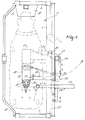
- Figure 3 is a side view of this milking box;
- Figure 4 is a plan view of an alternative embodiment of the milking box.
-
- Figure 1 shows two
boxes frame 3 consisting of aframe portion 4 forming a longitudinal side of the two boxes, theframe portions boxes boxes reference numerals 8 and 9 and the exit doors of the boxes by 10 and 11. Thedoors box 1, whereas thedoors 9 and 11 are pivotal approximately halfway the longitudinal side ofbox 2. Near their ends thedoors 8 to 11 have aportion portions 12 to 15 are disposed such that, when the doors have been moved to a first opened state, illustrated by means of broken lines in Figure 1, the inwardly extendingportions 12 to 15 are predominantly located such that they are in alignment, parallel to the longitudinal direction of the two boxes. Particularly by moving theexit door 10 ofbox 1 and the entrance door 9 ofbox 2 to this first opened state, a lateral connecting passage is formed betweenbox 1 andbox 2 and an animal can be guided frombox 1 into thebox 2. In the Figure there is furthermore provided apartition 16 which extends transversely to the longitudinal direction of the boxes, more specifically in the region of the lateral frame portion 6 between the two boxes. Thispartition 16 is movable in a direction transversely of the longitudinal direction of the boxes, whilst thepartition 16 remains in alignment with the transverse frame portion 6. When the partition is in the position shown in Figure 1, then an animal can pass frombox 1 tobox 2 when thedoors 9 and 10 have been moved to the first opened state, whilst, when thepartition 16 has been moved towards the transverse frame portion 6 and thereafter thedoor 10 has been moved to a second opened state, illustrated by broken lines in Figure 1, then an animal can be returned frombox 1 to the shed of the construction. The system can operate in an excellent manner also without thepartition 16, as, by keeping the door 9 closed and moving thedoor 10 to the second opened state, an animal can be denied access tobox 2 and will be forced to enter the shed of the construction. However, for the case in which the area aside of thedoors 9 and 11 ofbox 2 are given a different destination, the movable partition is of importance. - The
boxes automatic feeding implement 17 and 18. Near these automatic feeders both boxes accommodate an animal identification sensor (not shown in the Figures) which is connected to a computer system, which animal identification sensors form an animal identification system in combination with a transponder worn by the animals. With the aid of this animal identification system it is permanently updated in the computer system which animal is present at which moment in which box. For that purpose the memory of the computer system has a separate file for each animal, in which file all relevant information about the relevant animal has also been stored. More in particular, in this file it is recorded when an animal has been milked for the last time, so that it is always known how much time has elapsed between the latest milking turn and the instant an animal has entered thebox 1, when an animal has calved last, when the lactation period of an animal has started, how much milk it yields in each milking turn, etc. This information is important to decide whether an animal may enter thebox 1, may be milked or not. Thebox 1 is therefore also provided with means for selecting the animals, whilst furthermore the opportunity can be used to clean and optionally massage the udder of the animal to stimulate the milk production, when by means of the animal identification system and the data in the file of the relevant animal in the memory of the computer system it has been decided that the animal may be milked, whilst in addition concentrate can be supplied to the animal in thebox 1. Thebox 2 is equipped as a milking box, into which an animal is admitted frombox 1 for the purpose of being milked, whilst additional concentrate can be fed to the animal if desired. - An animal which has recently calved, can automatically and/or to the livestock farmer's option be milked once or more times per 24 hour's period more frequently than the average number of times the other animals of the herd, to which the recently calved animal belongs, are milked. Likewise, depending on the beginning of the lactation period of an animal, the animal can be milked more or less times per 24 hour's period. In this and other cases it can automatically and/or to the livestock farmer's option be recorded in the computer system how many times a given animal can be milked in each 24 hour's period and the animals can be stimulated to go at the proper moments, summoned by the computer system, to the
boxes milking boxes - Figures 2 and 3 are a plan view and a side view, respectively, of only the
milking box 2. For the milking operation amilking robot 19 is present, which includes arobot arm construction 20, at the end of which arobot head 21 is disposed which serves as a carrier for fourteat cups 22. In addition, themilking robot 19 includes acarrier structure 23 for adetection member 24. Therobot arm construction 20 carrying therobot head 21 and theteat cups 22 is independently movable with respect to thecarrier structure 23 with thedetection member 24. - The
robot arm structure 20 is constituted by acarrier element 25 which is movable over arail 37, parallel to theframe portion 4, and to which acarrier 27 which can be moved up and down is attached by means of aparallelogram structure 26. At its bottom side thecarrier 27 is provided with a supporting element 28 which is rigidly connected thereto and extends inwardly and slightly forwardly. Arobot arm 30 is connected capable of pivoting about an upwardly directedshaft 29 to the supporting element 28. Therobot head 21 is attached capable of pivoting about an upwardly directed shaft 31 to the end of thearm 30. By a motion in the longitudinal direction of themilking box 2, a pivotal movement about theshaft 29 and, if necessary, by pivoting therobot head 21 about the shaft 31 with respect to therobot arm 30, all the desired movements of therobot head 21 in a horizontal plane to under the animal standing in thebox 2 are possible, whilst with the aid of theparallelogram structure 26 an up and down motion can be obtained. All these movements are controlled by, preferably pneumatical, cylinders, since these cylinders slightly yield when the animal pushes or kicks against the robot arm structure. The pneumatic working cylinders are controlled by the computer system. - Independently of the
robot arm structure 20, which is in a position more advanced to the leading side of themilking box 2, there is disposed, near the rear side of themilking box 2, thecarrier structure 23 for thedetection member 24. Also thecarrier structure 23 includes acarrier element 32 which is movable along therail 37. Thiscarrier element 32 is constituted by a hollow beam 33, within which aninner beam 34 is disposed capable of moving upwardly and downwardly. At the bottom side of this inner beam 34 acarrier 35 is present which is movable transversely to the longitudinal direction of themilking box 2 and at the end of which carrier 35 a supportingelement 36 for thedetection member 24 is attached. By the capability of moving in the longitudinal direction of themilking box 2, the capability of moving in height of theinner beam 34 with respect to the hollow beam 33 and the capability of transverse motion of thecarrier 35 with the supportingelement 36 and thedetection member 24 with respect to theinner beam 34, a motional feature of thedetection member 24 in three coordinates is realized, which motional feature itself is rendered possible with the aid of the, preferably computer-controlled, pneumatic cylinders. In Figure 1 it is shown how, with the aid of thecarrier structure 23, thedetection member 24 is adjusted to a position in which this detection member has been moved passing between the two hind legs of the animal present in themilking box 2 to a position close to the hind teats of the animal. As thedetection member 24 is designed as a laser which is pivotal about an upwardly directed shaft and produces a very narrow scanning beam, which is moved from a short distance over the teats of the animal, an extremely accurate positional determination of the teats is made possible. Thedetection member 24 can be adjusted to the position shown by moving the detection member to a central position between the two longitudinal sides and by moving it thereafter to a position which is determined from the computer system on the basis of the data stored in the file of the animal about the position of the teats. Here the motion of thedetection member 24 is performed totally independently of the robotarm carrier structure 20 of theteat cups 22 and is therefore not obstructed thereby in any way. When by means of thedetection member 24 the position of the individual teats has been stored, theteat cups 22 which have been moved in the meantime to under the animal's udder, can be connected. - Figure 4 shows an alternative embodiment of the
carrier structure 23 for thedetection member 24. Thedetection member 24 is then directly disposed at the end of thecarrier 35. As a result thereof it is possible to approach the udder of the animal present in themilking box 2 from the side using thedetection member 24. As in this situation thecarrier structure 23 and, more in particular thecarrier 35, is in a more advanced position, it will be necessary for therobot arm structure 20 to be adjusted to a more advanced position so as to be able to pivot to under the animal without any obstruction by thecarrier structure 23. Not until therobot head 21 has been moved to under the animal, more specifically to a position indicated by broken lines, therobot head 21 can be moved rearwardly towards the udder. - In the foregoing description the place in which the animals are present during milking is designated as a milking box. It will be obvious that this milking box may be of any conceivable design; it may also form part of the shed. The invention is therefore not limited to the construction shown here and is also not limited to the embodiments described sofar, but also relates to all kinds of modifications thereof, of course in sofar they are within the scope of the accompanying claims.
Claims (18)
- A construction or a similar arrangement for automatically milking animals, such as cows, having a milking box (2) comprising a milking robot (19) with a movable robot head (21), said robot head serving as a carrier for one or a number of teat cups (22), said milking box further comprising a detection member (24) for determining the position of the teats of the animals, characterized in that the detection member (24) and the robot head (21) are movable independently of each other.
- A construction as claimed in claim 1, characterized in that the detection member (24) is movable into the milking box (2) in one direction and that the robot head (21) is movable into the milking box (2) from another direction.
- A construction as claimed in any one of the preceding claims, characterized in that the detection member (24) is attached to the frame of the milking box (2) capable of being moved in three directions.
- A construction as claimed in claim 3, characterized in that the detection member (24) is disposed such that it is movable in the vertical, transverse and longitudinal directions.
- A construction as claimed in any one of the preceding claims, characterized in that, during coupling of the teat cups (22) to the teats of an animal, the detection member (24) is in a position at one side of the teats and the teat cups are guided by the robot head (21) to the teats from another side of the teats.
- A construction as claimed in any one of the preceding claims, characterized in that the detection member (24) is movable into the milking box (2) at the rear side of the milking box (2).
- A construction as claimed in claim 6, characterized in that, during coupling of the teat cups (22) to the teats of an animal, the detection member (24) is in a position near the rear teats of the animal.
- A construction as claimed in any one of the preceding claims, characterized in that the detection member (24) is movable into the milking box (2) from the side of the milking box (2).
- A construction as claimed in claim 8, characterized in that, during coupling of the teat cups (22) to the teats of an animal, the detection member (24) is in a position near the side of the udder of the animal.
- A construction as claimed in any one of the preceding claims, characterized in that the detection member (24) is disposed rotatably, more in particular capable of reciprocating, about an upwardly directed shaft.
- A construction as claimed in any one of the preceding claims, characterized in that the detection member (24) includes a laser.
- A construction as claimed in any one of the preceding claims, characterized in that a radiation scanning beam is obtained with the aid of the detection member (24) for detecting the teats from the rear side.
- A construction as claimed in any one of the preceding claims, characterized in that a radiation scanning beam is obtained with the aid of the detection member (24) for detecting the teats from the side.
- A construction as claimed in any one of the preceding claims, characterized in that, with the aid of the detection member (24), a radiation scanning beam is obtained, of which the scanning spot is aimed at the upper side of the teats during coupling of the teat cups (22) to the teats of an animal.
- A construction as claimed in any one of the preceding claims, characterized in that the milking robot (19) includes a robot arm construction (20), of which the robot head (21) forms the end, this robot arm construction (20) being movably attached to the frame (3) of the milking box (2) near the front legs of an animal present in the milking box (2).
- A construction as claimed in claim 15, characterized in that the robot arm construction (20) is movable along a straight guide (37) at the longitudinal side of the milking box (2), whilst the robot head (21) is movable in the upward direction, and, with respect to the robot arm construction (20), pivotally about an upwardly directed shaft (31).
- A construction as claimed in any one of the preceding claims, characterized in that moving the detection member (24) and the robot head (21) is effected by means of pneumatic cylinders and/or stepper motors.
- A construction as claimed in any one of the preceding claims, characterized in that the milking box (2) includes a cow identification sensor which is connected to the computer and, in combination with a transponder to be worn by the animals, forms an animal identification system, with the aid of which the relevant data files relating to the individual animals are read from the computer, on the basis of which data files the at least coarse positioning of the detection member (24) and the robot head (21) near and under, respectively, the udder of an animal, can optionally be effected.
Priority Applications (1)
| Application Number | Priority Date | Filing Date | Title |
|---|---|---|---|
| DE9422334U DE9422334U1 (en) | 1993-08-09 | 1994-08-05 | Automatic milking device for animals |
Applications Claiming Priority (2)
| Application Number | Priority Date | Filing Date | Title |
|---|---|---|---|
| NL9301378A NL9301378A (en) | 1993-08-09 | 1993-08-09 | Device for automatic milking of animals. |
| NL9301378 | 1993-08-09 |
Publications (3)
| Publication Number | Publication Date |
|---|---|
| EP0638232A1 EP0638232A1 (en) | 1995-02-15 |
| EP0638232B1 true EP0638232B1 (en) | 1999-12-01 |
| EP0638232B2 EP0638232B2 (en) | 2004-12-29 |
Family
ID=19862741
Family Applications (1)
| Application Number | Title | Priority Date | Filing Date |
|---|---|---|---|
| EP19940202259 Expired - Lifetime EP0638232B2 (en) | 1993-08-09 | 1994-08-05 | A construction for automatically milking animals |
Country Status (3)
| Country | Link |
|---|---|
| EP (1) | EP0638232B2 (en) |
| DE (1) | DE69421855T3 (en) |
| NL (1) | NL9301378A (en) |
Families Citing this family (2)
| Publication number | Priority date | Publication date | Assignee | Title |
|---|---|---|---|---|
| DK1120036T3 (en) * | 1996-05-23 | 2006-11-27 | Maasland Nv | Construction comprising a compartment for animals |
| ES2197470T3 (en) * | 1997-05-21 | 2004-01-01 | Dsm Ip Assets B.V. | METHOD TO PREPARE MELAMINE. |
Family Cites Families (3)
| Publication number | Priority date | Publication date | Assignee | Title |
|---|---|---|---|---|
| NL8600076A (en) * | 1986-01-16 | 1987-08-17 | Lely Nv C Van Der | METHOD AND APPARATUS FOR MILKING AN ANIMAL. |
| EP0306579B1 (en) * | 1987-09-08 | 1992-01-02 | Centre National Du Machinisme Agricole, Du Genie Rural, Des Eaux Et Des Forets (Cemagref) | Automatic milking machine |
| DE3702465A1 (en) * | 1987-01-28 | 1988-08-11 | Duevelsdorf & Sohn Gmbh & Co K | METHOD AND DEVICE FOR MILKING AND GGFS. FEEDING OF FREEDOMING, IDENTIFICATION-BASED COWS |
-
1993
- 1993-08-09 NL NL9301378A patent/NL9301378A/en not_active Application Discontinuation
-
1994
- 1994-08-05 DE DE1994621855 patent/DE69421855T3/en not_active Expired - Lifetime
- 1994-08-05 EP EP19940202259 patent/EP0638232B2/en not_active Expired - Lifetime
Also Published As
| Publication number | Publication date |
|---|---|
| EP0638232A1 (en) | 1995-02-15 |
| DE69421855T3 (en) | 2005-09-01 |
| EP0638232B2 (en) | 2004-12-29 |
| NL9301378A (en) | 1995-03-01 |
| DE69421855D1 (en) | 2000-01-05 |
| DE69421855T2 (en) | 2000-06-29 |
Similar Documents
| Publication | Publication Date | Title |
|---|---|---|
| EP0634097B1 (en) | A construction for automatically milking animals | |
| EP0313109B1 (en) | Implement for milking animals | |
| EP1120034B1 (en) | A construction including an implement for automatically milking animals | |
| US5596945A (en) | Construction for automatically milking animals | |
| AU6123098A (en) | A method of milking animals | |
| EP1131997B1 (en) | A construction including an implement for milking animals | |
| EP0951824B1 (en) | A construction for automatically milking animals | |
| EP1042952B1 (en) | A construction for automatically milking animals | |
| EP0716567B1 (en) | A construction including an implement for automatically milking animals | |
| EP0990385B1 (en) | A construction for milking animals | |
| EP0638232B1 (en) | A construction for automatically milking animals | |
| CA2388923A1 (en) | Means for improved milking | |
| EP0634095B1 (en) | A construction for automatically milking animals |
Legal Events
| Date | Code | Title | Description |
|---|---|---|---|
| PUAI | Public reference made under article 153(3) epc to a published international application that has entered the european phase |
Free format text: ORIGINAL CODE: 0009012 |
|
| AK | Designated contracting states |
Kind code of ref document: A1 Designated state(s): DE FR GB NL SE |
|
| 17P | Request for examination filed |
Effective date: 19950801 |
|
| 17Q | First examination report despatched |
Effective date: 19980514 |
|
| GRAG | Despatch of communication of intention to grant |
Free format text: ORIGINAL CODE: EPIDOS AGRA |
|
| GRAG | Despatch of communication of intention to grant |
Free format text: ORIGINAL CODE: EPIDOS AGRA |
|
| GRAH | Despatch of communication of intention to grant a patent |
Free format text: ORIGINAL CODE: EPIDOS IGRA |
|
| GRAH | Despatch of communication of intention to grant a patent |
Free format text: ORIGINAL CODE: EPIDOS IGRA |
|
| GRAA | (expected) grant |
Free format text: ORIGINAL CODE: 0009210 |
|
| AK | Designated contracting states |
Kind code of ref document: B1 Designated state(s): DE FR GB NL SE |
|
| REF | Corresponds to: |
Ref document number: 69421855 Country of ref document: DE Date of ref document: 20000105 |
|
| ET | Fr: translation filed | ||
| PLBQ | Unpublished change to opponent data |
Free format text: ORIGINAL CODE: EPIDOS OPPO |
|
| PLBI | Opposition filed |
Free format text: ORIGINAL CODE: 0009260 |
|
| PLBF | Reply of patent proprietor to notice(s) of opposition |
Free format text: ORIGINAL CODE: EPIDOS OBSO |
|
| 26 | Opposition filed |
Opponent name: PROLION B.V. Effective date: 20000901 |
|
| NLR1 | Nl: opposition has been filed with the epo |
Opponent name: PROLION B.V. |
|
| PLBF | Reply of patent proprietor to notice(s) of opposition |
Free format text: ORIGINAL CODE: EPIDOS OBSO |
|
| PLBF | Reply of patent proprietor to notice(s) of opposition |
Free format text: ORIGINAL CODE: EPIDOS OBSO |
|
| REG | Reference to a national code |
Ref country code: GB Ref legal event code: IF02 |
|
| PLAW | Interlocutory decision in opposition |
Free format text: ORIGINAL CODE: EPIDOS IDOP |
|
| APAC | Appeal dossier modified |
Free format text: ORIGINAL CODE: EPIDOS NOAPO |
|
| APAC | Appeal dossier modified |
Free format text: ORIGINAL CODE: EPIDOS NOAPO |
|
| RAP2 | Party data changed (patent owner data changed or rights of a patent transferred) |
Owner name: MAASLAND N.V. |
|
| NLT2 | Nl: modifications (of names), taken from the european patent patent bulletin |
Owner name: MAASLAND N.V. |
|
| APBU | Appeal procedure closed |
Free format text: ORIGINAL CODE: EPIDOSNNOA9O |
|
| PUAH | Patent maintained in amended form |
Free format text: ORIGINAL CODE: 0009272 |
|
| STAA | Information on the status of an ep patent application or granted ep patent |
Free format text: STATUS: PATENT MAINTAINED AS AMENDED |
|
| 27A | Patent maintained in amended form |
Effective date: 20041229 |
|
| AK | Designated contracting states |
Kind code of ref document: B2 Designated state(s): DE FR GB NL SE |
|
| APAA | Appeal reference recorded |
Free format text: ORIGINAL CODE: EPIDOS REFN |
|
| NLR2 | Nl: decision of opposition |
Effective date: 20041229 |
|
| REG | Reference to a national code |
Ref country code: SE Ref legal event code: RPEO |
|
| NLR3 | Nl: receipt of modified translations in the netherlands language after an opposition procedure | ||
| APAH | Appeal reference modified |
Free format text: ORIGINAL CODE: EPIDOSCREFNO |
|
| ET3 | Fr: translation filed ** decision concerning opposition | ||
| REG | Reference to a national code |
Ref country code: FR Ref legal event code: ST Effective date: 20080131 |
|
| PGFP | Annual fee paid to national office [announced via postgrant information from national office to epo] |
Ref country code: FR Payment date: 20070817 Year of fee payment: 14 |
|
| PG25 | Lapsed in a contracting state [announced via postgrant information from national office to epo] |
Ref country code: FR Free format text: LAPSE BECAUSE OF NON-PAYMENT OF DUE FEES Effective date: 20060831 |
|
| PGFP | Annual fee paid to national office [announced via postgrant information from national office to epo] |
Ref country code: NL Payment date: 20100824 Year of fee payment: 17 |
|
| PGFP | Annual fee paid to national office [announced via postgrant information from national office to epo] |
Ref country code: SE Payment date: 20100827 Year of fee payment: 17 |
|
| PGFP | Annual fee paid to national office [announced via postgrant information from national office to epo] |
Ref country code: GB Payment date: 20100825 Year of fee payment: 17 |
|
| PGFP | Annual fee paid to national office [announced via postgrant information from national office to epo] |
Ref country code: DE Payment date: 20110830 Year of fee payment: 18 |
|
| REG | Reference to a national code |
Ref country code: NL Ref legal event code: V1 Effective date: 20120301 |
|
| REG | Reference to a national code |
Ref country code: SE Ref legal event code: EUG |
|
| GBPC | Gb: european patent ceased through non-payment of renewal fee |
Effective date: 20110805 |
|
| PG25 | Lapsed in a contracting state [announced via postgrant information from national office to epo] |
Ref country code: NL Free format text: LAPSE BECAUSE OF NON-PAYMENT OF DUE FEES Effective date: 20120301 |
|
| PG25 | Lapsed in a contracting state [announced via postgrant information from national office to epo] |
Ref country code: GB Free format text: LAPSE BECAUSE OF NON-PAYMENT OF DUE FEES Effective date: 20110805 |
|
| PG25 | Lapsed in a contracting state [announced via postgrant information from national office to epo] |
Ref country code: SE Free format text: LAPSE BECAUSE OF NON-PAYMENT OF DUE FEES Effective date: 20110806 |
|
| PG25 | Lapsed in a contracting state [announced via postgrant information from national office to epo] |
Ref country code: DE Free format text: LAPSE BECAUSE OF NON-PAYMENT OF DUE FEES Effective date: 20130301 |
|
| REG | Reference to a national code |
Ref country code: DE Ref legal event code: R119 Ref document number: 69421855 Country of ref document: DE Effective date: 20130301 |
|
| PG25 | Lapsed in a contracting state [announced via postgrant information from national office to epo] |
Ref country code: FR Free format text: LAPSE BECAUSE OF NON-PAYMENT OF DUE FEES Effective date: 20070831 |