EP0736206B1 - Method and apparatus for quadratic interpolation - Google Patents
Method and apparatus for quadratic interpolation Download PDFInfo
- Publication number
- EP0736206B1 EP0736206B1 EP95902733A EP95902733A EP0736206B1 EP 0736206 B1 EP0736206 B1 EP 0736206B1 EP 95902733 A EP95902733 A EP 95902733A EP 95902733 A EP95902733 A EP 95902733A EP 0736206 B1 EP0736206 B1 EP 0736206B1
- Authority
- EP
- European Patent Office
- Prior art keywords
- signal
- signal sample
- sample
- response
- producing
- Prior art date
- Legal status (The legal status is an assumption and is not a legal conclusion. Google has not performed a legal analysis and makes no representation as to the accuracy of the status listed.)
- Expired - Lifetime
Links
Images


Classifications
-
- G—PHYSICS
- G06—COMPUTING; CALCULATING OR COUNTING
- G06F—ELECTRIC DIGITAL DATA PROCESSING
- G06F17/00—Digital computing or data processing equipment or methods, specially adapted for specific functions
- G06F17/10—Complex mathematical operations
- G06F17/17—Function evaluation by approximation methods, e.g. inter- or extrapolation, smoothing, least mean square method
Definitions
- the present invention relates in general to interpolations and more particularly to a quadratic interpolator for generating a series of output samples forming an approximate curve between successive input signal samples.
- interpolation has generally been restricted to either linear interpolation or cubic interpolation.
- Quadratic interpolation has not been hitherto implemented in digital signal processing systems because prior art quadratic interpolators are known to be space variant and to introduce phase distortion in the output signal.
- One paper that is often cited as being the definitive paper on this subject is by R.W. Schafer and L.R. Rabiner and is entitled "A Digital Signal Processing Approach to Interpolation". Proceedings of the IEEE, volume 61, June 1973.
- Linear interpolation has been preferred over cubic interpolation in the field of digital signal processing since, even though the frequency response of linear interpolation is inferior to that of cubic interpolation, cubic interpolation systems require a great deal more calculation and storage hardware to implement than linear interpolation.
- FR-A-2 311 357 discloses a method of approximating a series of signal samples y(t) by a plurality of parabolas. However, the approximated curve does not pass through every sample point.
- US-A-4 031 370 discloses an interpolation method which uses higher order polynomials, in particular a fourth order polynomial interpolation to obtain up to an eighth order interpolation in two iterations of the fourth order method.
- digital signal processing apparatus for performing quadratic interpolation on sampled values of a physical signal to produce an output signal sample y(x) for each of a plurality of reference values x and based on known signal samples y(-1), y(0), and y(1) spaced apart a predetermined equal amount, x being in a range of one-half of said predetermined equal amount on either side of signal sample y(0)
- a method of digital signal processing of a sampled value of a physical signal for producing a quadratic interpolated output signal sample y(x) for each of a plurality of reference values x and based on known signal samples y(-1), y(0), and y(1) spaced apart a predetermined equal amount, x being in a range of one-half of said predetermined equal amount on either side of signal sample y(0), said method comprising the steps of:
- the method and apparatus according to the invention can implement quadratic interpolation with low phase distortion and an absence of discontinuities caused by inappropriate selection of reference points.
- Reference points can be determined for implementing the interpolation in such a manner as to eliminate phase distortion and spatial variation. The determination of these reference points can be accomplished using a linear interpolator for selecting the midpoint between input samples.
- the interpolated points are used as reference points for a quadratic interpolation where the space between the reference points is one half the distance between respective known sample points.
- the output signal sample values of y are interpolated in a plus or minus 0.5 range about the centre sample, assuming an arbitrary sample spacing of 1.0.
- the principles of the present invention may be extended for sample spacing other than 1, by simply selecting reference points which are one half of the given sample spacing.
- FIG. 1A a curve is shown which is an approximation utilizing known sample points A, B, C, D, E, and F utilizing linear interpolation.
- the curves between respective ones of the points A, B, C, etc. are linear. This results in an extremely rough approximation of the actual curve between the known signal sample points, and also results in the generation of significant harmonic distortion due to the sharp edges of the approximated curve.
- interpolated reference points are utilized in a quadratic formula where the space between the reference points is 0.5 as opposed to 1.0, yielding the curve of Figure 2B.
- the three data points y(-1),y(0) and y(1) are received via an input 30 and stored in respective ones of series-connected registers 31, 32 and 33.
- An adder 34 adds the signal samples y(-1) and y(1) and applies the resulting signal to an non-inverting input of subtractor 35.
- the second reference sample point y(0) is shifted one bit to the left in shift register 36, which has the effect of multiplying the value y(0) by 2.
- the output of shift register 36 is applied to the inverting input of subtractor 35.
- the value of x is received on input 39 and is applied to both inputs of a multiplier 40 which therefore squares the value of x.
- Multipliers 41 and 42 perform the operations "ax 2 " and "bx", respectively.
- the three input adder 43 sums the outputs of multipliers 41 and 42 with y(0) received from storage register 32, and in response produces the output interpolated value y(x).
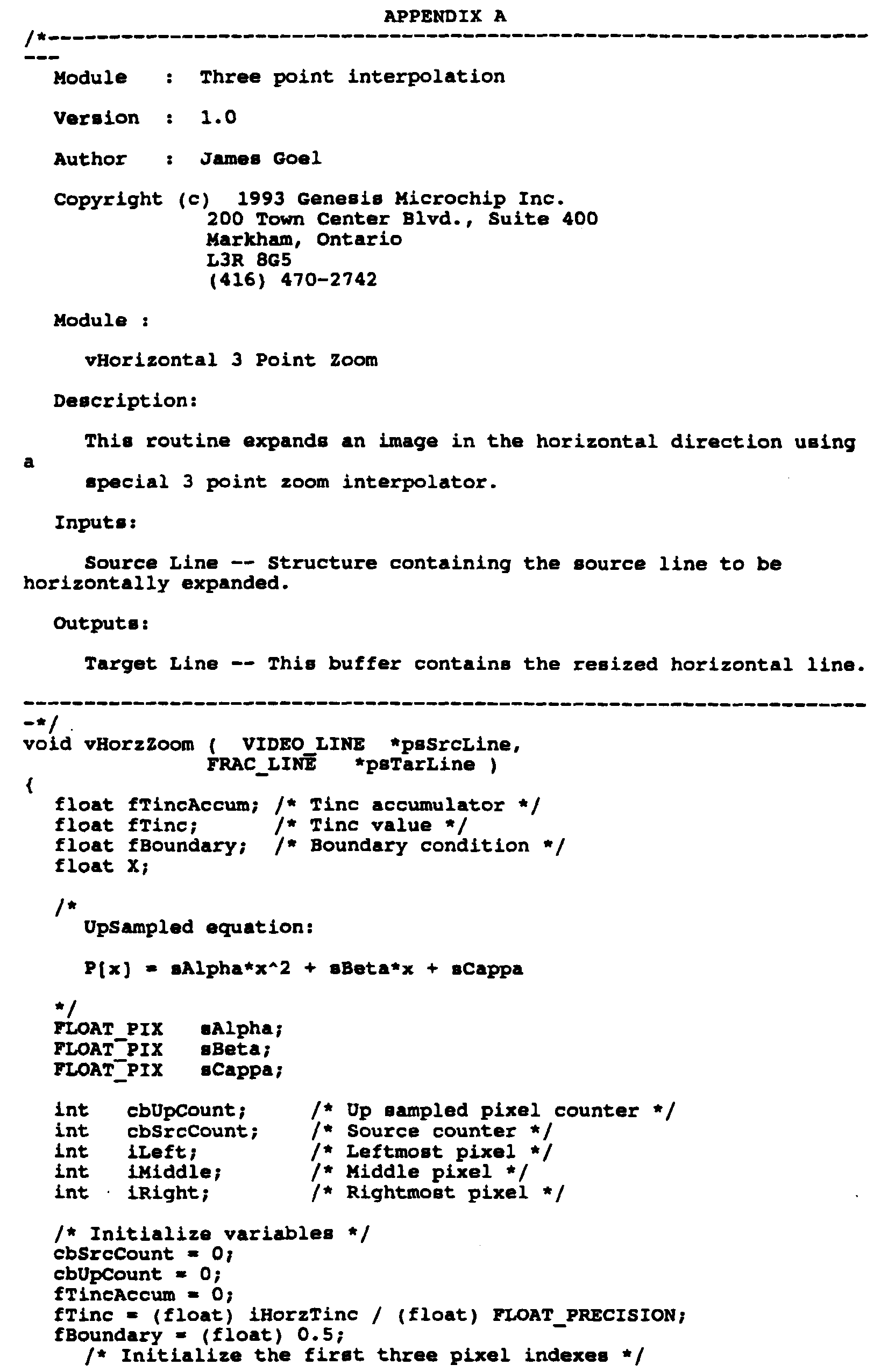
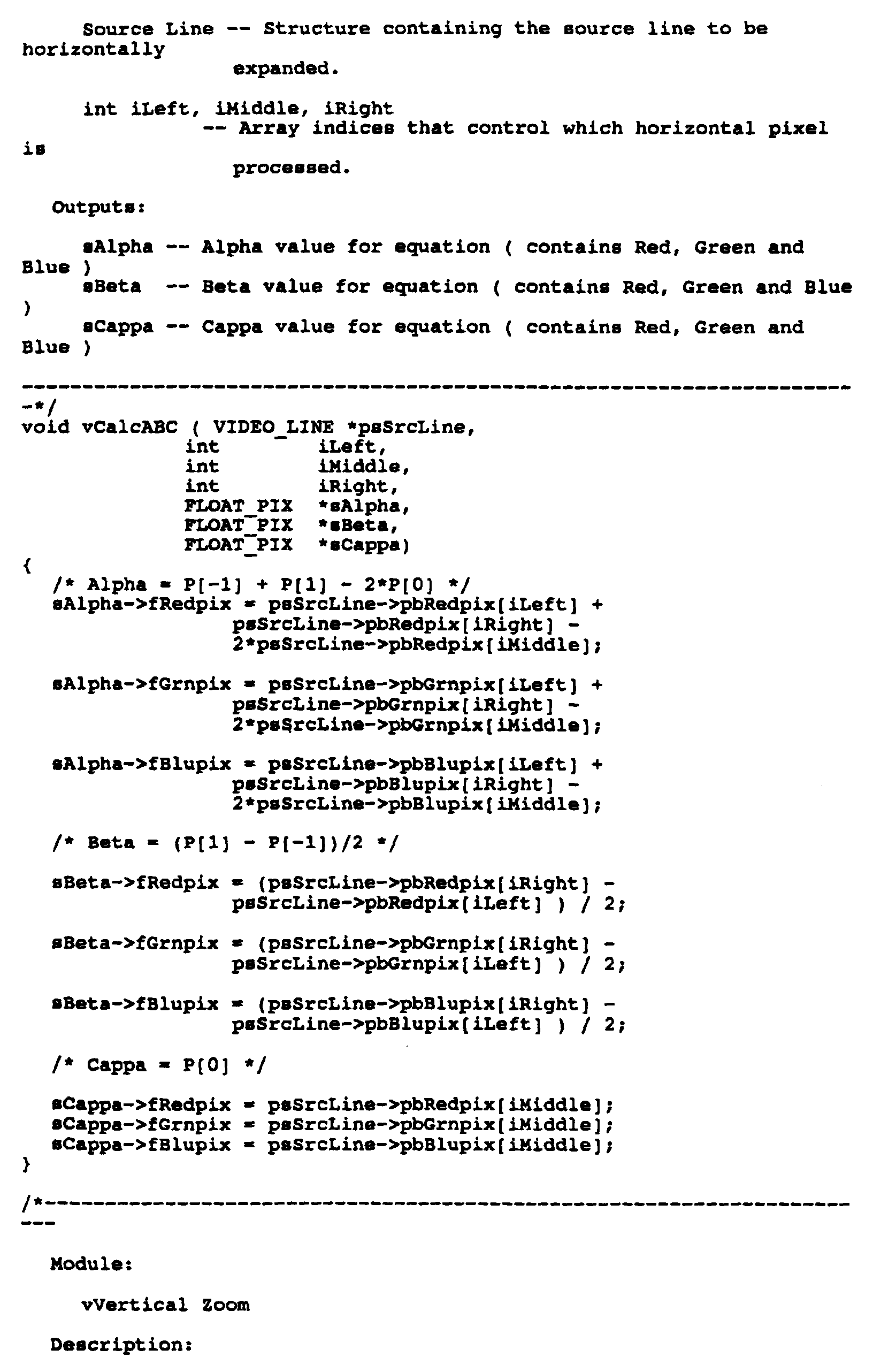
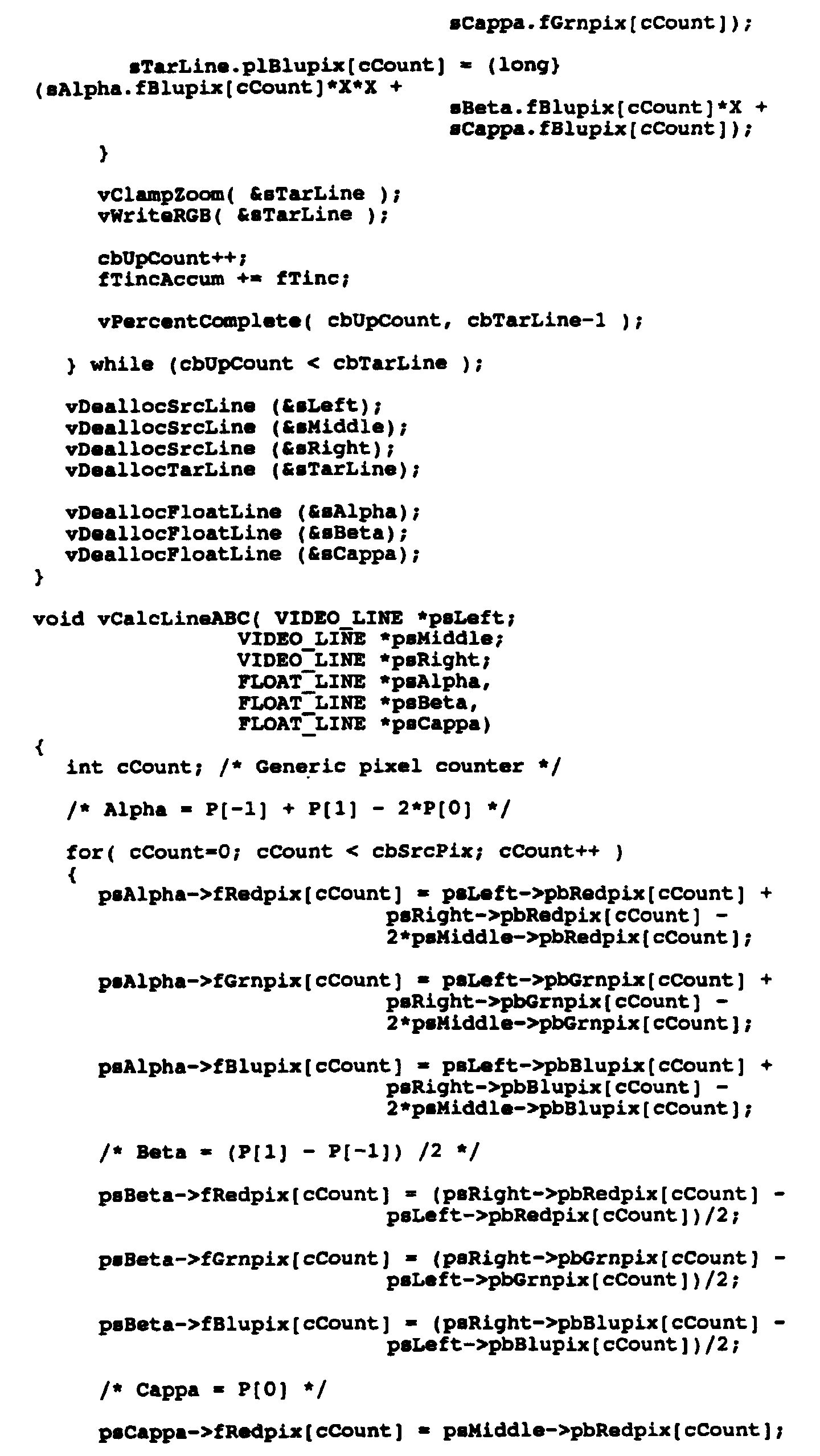
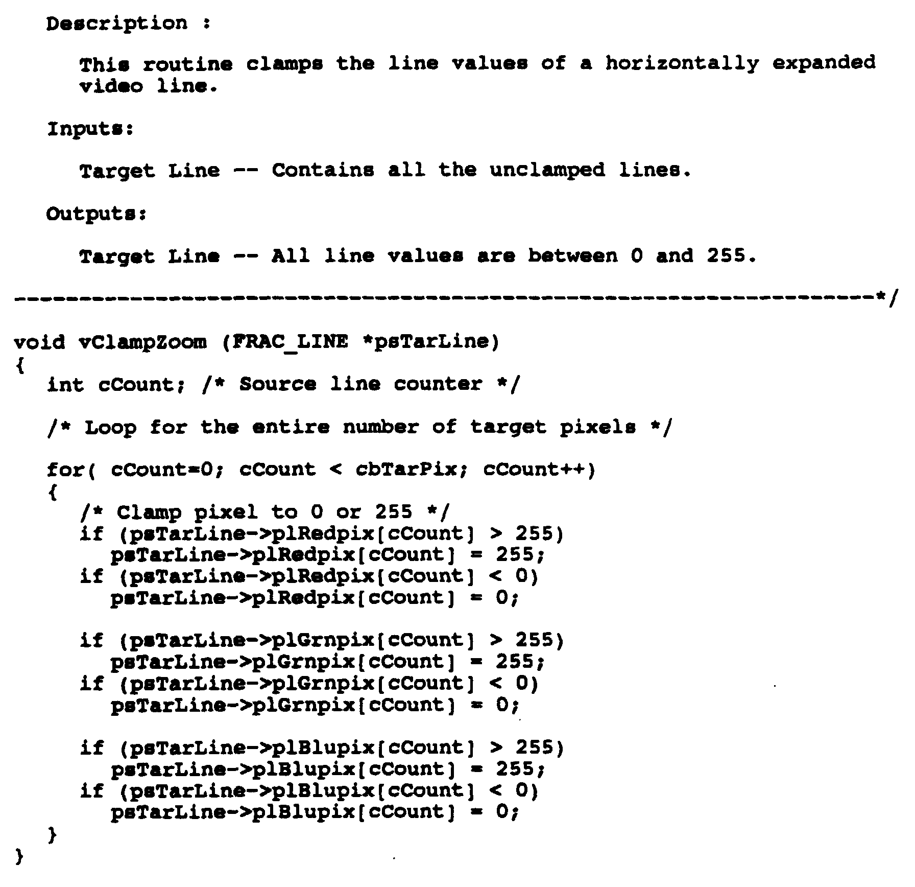
- the method of quadratic interpolation according to the present invention may be implemented in software.
- the C source code listing for one such possible software implementation of the present invention is appended hereto as appendix A.
Abstract
Description
- The present invention relates in general to interpolations and more particularly to a quadratic interpolator for generating a series of output samples forming an approximate curve between successive input signal samples.
- Mathematical interpolation has been used for many years in many fields of science for approximating curves between known signal sample points. The subject of interpolation is treated in many text-books, such as Robert L. Ketter and Sherwood P. Prawel Jr., entitled "Modern Methods of Engineering Computation", McGraw Hill 1969. Many advanced methods of interpolation have been used in digital signal processing for many years, as described in Rabiner L.R. and Schafer "Digital Processing of Speech Signals", Prentice Hall, 1978, as well as George Wolberg entitled "Digital Image Warping", IEEE Computer Society Press, 1988.
- According to the known prior art interpolation techniques utilized in digital signal processing, interpolation has generally been restricted to either linear interpolation or cubic interpolation. Quadratic interpolation has not been hitherto implemented in digital signal processing systems because prior art quadratic interpolators are known to be space variant and to introduce phase distortion in the output signal. One paper that is often cited as being the definitive paper on this subject is by R.W. Schafer and L.R. Rabiner and is entitled "A Digital Signal Processing Approach to Interpolation". Proceedings of the IEEE, volume 61, June 1973.
- Linear interpolation is a commonly used form of interpolation in which a straight line of the form:
- Linear interpolation has been preferred over cubic interpolation in the field of digital signal processing since, even though the frequency response of linear interpolation is inferior to that of cubic interpolation, cubic interpolation systems require a great deal more calculation and storage hardware to implement than linear interpolation.
- Other methods of interpolation are also known. FR-A-2 311 357 discloses a method of approximating a series of signal samples y(t) by a plurality of parabolas. However, the approximated curve does not pass through every sample point. As a further example, US-A-4 031 370 discloses an interpolation method which uses higher order polynomials, in particular a fourth order polynomial interpolation to obtain up to an eighth order interpolation in two iterations of the fourth order method.
- Quadratic interpolation as described in the above discussed reference of Ketter and Prawel, and many others, is achieved by fitting a quadratic equation of the form
- The main disadvantage of using quadratic interpolation in digital signal processing and other applications is the distortion which occurs at the transition from one set of sample points to another. As discussed in greater detail below with reference to the Figures, incorrect selection of a reference sample point can result in significant curve discontinuities (i.e. distortion) in the output interpolated curve approximation between the points.
- According to the present invention there is provided digital signal processing apparatus for performing quadratic interpolation on sampled values of a physical signal to produce an output signal sample y(x) for each of a plurality of reference values x and based on known signal samples y(-1), y(0), and y(1) spaced apart a predetermined equal amount, x being in a range of one-half of said predetermined equal amount on either side of signal sample y(0), said quadratic interpolator comprising means operative to output a first signal having value
- According to the present invention, there is further provided a circuit for producing an output signal sample y(x) for each one of a plurality of reference values x intermediate three known signal samples y(-1), y(0) and y(1), wherein said three known signal samples are spaced apart a predetermined equal amount, and wherein y(x) is produced for x in a range of one-half said predetermined equal amount on either side of signal sample y(0), comprising a first input for receiving said three known signal samples y(-1), y(0) and y(1), a second input for receiving said each one of said plurality of reference values x, first, second and third storage registers connected in series to said first input for storing said three known signal samples y(-1), y(0) and y(1), respectively, a first adder connected to said first and third storage registers for adding said signal samples y(-1) and y(1) and in response producing a first sum signal sample y(-1) + y(1), a first shift register connected to said second storage register for left-shifting said signal sample y(0) by one bit and in response producing a first doubled signal sample 2y(0), a first subtracter connected to said first adder and said first shift register for subtracting said first doubled signal sample 2y(0) from said first sum signal sample
- According to the present invention there is also provided a method of digital signal processing of a sampled value of a physical signal for producing a quadratic interpolated output signal sample y(x) for each of a plurality of reference values x and based on known signal samples y(-1), y(0), and y(1) spaced apart a predetermined equal amount, x being in a range of one-half of said predetermined equal amount on either side of signal sample y(0), said method comprising the steps of:
- a) determining signal
signal - b) producing output signal
-
- Advantageously, the method and apparatus according to the invention can implement quadratic interpolation with low phase distortion and an absence of discontinuities caused by inappropriate selection of reference points. Reference points can be determined for implementing the interpolation in such a manner as to eliminate phase distortion and spatial variation. The determination of these reference points can be accomplished using a linear interpolator for selecting the midpoint between input samples. Next, the interpolated points are used as reference points for a quadratic interpolation where the space between the reference points is one half the distance between respective known sample points.
- Thus, the quadratic interpolation implemented according to the present invention may be expressed by the following formula:
- The operations of linear interpolation and quadratic interpolation discussed above can be performed simultaneously by reforming the quadratic interpolation equation based on the output of the linear interpolation equation. The resulting quadratic formula is as follows:
- The output signal sample values of y are interpolated in a plus or minus 0.5 range about the centre sample, assuming an arbitrary sample spacing of 1.0. However, the principles of the present invention may be extended for sample spacing other than 1, by simply selecting reference points which are one half of the given sample spacing.
- A description of the prior art and an embodiment of the present invention is provided hereinbelow with reference to the following drawings in which:
- Figure 1A is an approximated curve between a plurality of known signal sample points generated by linear interpolation according to the prior art;
- Figure 1B shows two possible approximation curves obtained utilizing quadratic interpolation according to the prior art;
- Figure 2A shows the determination of reference points selected at the mid-point between input samples using linear interpolation, according to one aspect of the present invention;
- Figure 2B shows a curve constructed using quadratic interpolation using the mid-points determined by linear interpolation in Figure 2A, according to another aspect of the present invention; and
- Figure 3 is a block circuit diagram of a quadratic interpolator according to the preferred embodiment.
-
- Turning to Figure 1A, a curve is shown which is an approximation utilizing known sample points A, B, C, D, E, and F utilizing linear interpolation. As will be noted, since linear interpolation is being utilized, the curves between respective ones of the points A, B, C, etc. are linear. This results in an extremely rough approximation of the actual curve between the known signal sample points, and also results in the generation of significant harmonic distortion due to the sharp edges of the approximated curve.
- By way of contrast, the curves 1 and 2 illustrated in Figure 1B, which have been generated by utilizing quadratic interpolation, are much smoother but are otherwise close in approximation to the curve generated by linear interpolation (Figure 1A). However, as discussed above, the main disadvantage of utilizing quadratic interpolation in digital signal processing results from spatial variance and phase distortion during the transition from one set of samples to another. While lines 1 and 2 in Figure 1B represent a possible approximation curve generated by quadratic interpolation and which is also generated by the same quadratic interpolation but is quite similar to the one described by the linear interpolation of Figure 1A, the curve represented by lines 3 and 4 is radically different. The difference between obtaining lines 1 and 2 or lines 3 and 4 using the same quadratic interpolation is a matter of which three pixels are used as the reference points for the interpolation (curve 1 uses points B, C, D and curve 2 used points D, E, F whereas curve 3 uses points A, B, C and curve 4 uses points C, D, E). Lines 3 and 4 show a marked discontinuity that is extremely undesirable in digital signal processing and other scientific applications.
- Turning now to Figures 2A and 2B, according to the method of the present invention, rather than using the known signal sample points A, B, C, D, E and F as reference points, linear interpolation is used in the present invention to determine respective mid-points between the input samples, as shown in Figure 2A.
- Next, the interpolated reference points are utilized in a quadratic formula where the space between the reference points is 0.5 as opposed to 1.0, yielding the curve of Figure 2B.
- Turning now to the circuit diagram of Figure 3, a preferred implementation of the quadratic interpolator of the present invention is illustrated for an input sample data stream.
- The three data points y(-1),y(0) and y(1) are received via an input 30 and stored in respective ones of series-connected registers 31, 32 and 33.
- An adder 34 adds the signal samples y(-1) and y(1) and applies the resulting signal to an non-inverting input of subtractor 35. The second reference sample point y(0) is shifted one bit to the left in shift register 36, which has the effect of multiplying the value y(0) by 2. The output of shift register 36 is applied to the inverting input of subtractor 35. Thus the output of subtractor 35 corresponds to the value "a" from equation 6, namely:
- Subtractor 37 takes the difference between y(-1) and y(1) and the output thereof is right-shifted by one bit in shift register 38, yielding the value "b" from equation 6, namely:
- The value of x is received on input 39 and is applied to both inputs of a multiplier 40 which therefore squares the value of x. Multipliers 41 and 42 perform the operations "ax2" and "bx", respectively.
- The three input adder 43 sums the outputs of multipliers 41 and 42 with y(0) received from storage register 32, and in response produces the output interpolated value y(x).
- Although the preferred embodiment of the present invention has been defined in terms of a digital circuit shown in Figure 3, other circuit configurations are possible for achieving the same result.
- Furthermore, the method of quadratic interpolation according to the present invention may be implemented in software. The C source code listing for one such possible software implementation of the present invention is appended hereto as appendix A.
- All such modifications and alternative embodiments of the present invention are believed to be within the sphere and scope of this invention as defined by the claims appended hereto.


Claims (6)
- Digital signal processing apparatus for performing quadratic interpolation on sampled values of a physical signal to produce an output signal sample y(x) for each of a plurality of reference values x and based on known signal samples y(-1), y(0), and y(1) spaced apart a predetermined equal amount, x being in a range of one-half of said predetermined equal amount on either side of signal sample y(0), said quadratic interpolator comprising:means (31, 32, 33, 34, 35, 36, 37, 38) operative to output a first signal having valuemeans (39, 40, 41, 42, 43) operative to input x, to determine x2, to receive the first signal and the second signal, to produce a third signal having value x times b, to produce a fourth signal having a value x2 times a, and to add the third signal, the fourth signal and the signal sample y(0), and in response produce the output signal sample y(x).
- Digital signal processing apparatus according to claim 1, wherein said output means comprises:a first register (31) storing known signal sample y(-1),a second register (32), coupled to the first register (31), storing known signal sample y(0),a third register (33), coupled to the second register (32), storing known signal sample y(1),a first adder (34), coupled to the first register (31) and to the third register (33), adding the known signal sample y(-1) and the known signal sample y(1) together, and producing a first partial result signal,a first shifter (36), coupled to the second register (32), multiplying the known signal sample y(0) by 2, by shifting the known signal sample left, and outputting a shifted output,a first subtracter (35) having an inverting input and a non-inverting input, said first subtracter coupled to the first adder (34) and to the first shifter (36), receiving the first partial result signal at the non-inverting input and the shifted output at the inverting input, and outputting the first signal,a second subtracter (37) having an inverting input and a non-inverting input, said second subtracter coupled to the first register (31) and to the third register (33), receiving the known signal sample y(-1) at the inverting input and the known signal sample y(1) at the non-inverting input, and outputting a second partial result signal, anda second shifter (38), coupled to the second subtracter (37), receiving the second partial result signal and shifting the second partial result right, outputting the second signal; and wherein said input means comprises:a first multiplier (40) receiving the x and multiplying the x by itself, producing x2, and outputting a squared result signal,a second multiplier (41), coupled to the first multiplier (40) and to the first subtracter (35), multiplying the squared result signal by the first signal, and outputting a first multiplied result signal,a third multiplier (42), coupled to the second shifter (38), receiving the x, multiplying the x by the second signal, and outputting a second multiplied result signal, anda second adder (43), coupled to the second multiplier (41), to the third multiplier (42), and to the second register (32), adding the first multiplied result signal, the second multiplied result signal, and the known signal sample y(0),and outputting the output signal sample y(x).
- Digital signal processing apparatus according to claim 1, wherein said output means comprises:a) means (34) operative to add said signal samples y(-1) and y(1) and in response produce a first sum signal sample y(-1) + y(1);b) means (36) operative to double said signal sample y(0) and in response produce a first doubled signal sample 2y(0);c) means (35) operative to subtract first doubled signal sample 2y(0) from said first sum signal sampled) means (37) operative to subtract said signal sample y(-1) from said signal sample y(1) and in response produce a second difference signale) means (38) operative to halve said second difference signalf) means (40) operative to square said each one of said plurality of reference values x and in response produce a respective squared reference value x2;g) means (41) operative to multiply said first difference signal sample a by each said respective squared reference value x2 and in response produce a respective first product signal sample ax2;h) means (42) operative to multiply said first halved signal b by said each one of said plurality of reference values x and in response produce a respective second product signal sample bx; andi) means (43) operative to add each respective first product signal sample ax2 and second product signal sample bx and said known signal sample y(0) and in response produce said output signal sample y(x).
- Digital signal processing apparatus according to claim 1, comprising:a) a first input (30) for receiving said three known signal samples y(-1), y(0) and y(1);b) a second input (39) for receiving said each one of said plurality of reference values x;c) first, second and third storage registers (31, 32, 33) connected in series to said first input (30) for storing said three known signal samples y(-1), y(0) and y(1), respectively;d) a first adder (34) connected to said first (31) and third (33) storage registers for adding said signal samples y(-1) and y(1) and in response producing a first sum signal samplee) a first shift register (36) connected to said second storage register (32) for left-shifting said signal sample y(0) by one bit and in response producing a first doubled signal sample 2y(0);f) a first subtracter (35) connected to said first adder (34) and said first shift register (36) for subtracting said first doubled signal sample 2y(0) from said first sum signal sampleg) a second subtracter (37) connected to said first (31) and third (33) storage register for subtracting said signal sample y(-1) from said signal sample y(1) and in response producing a second difference signalh) a second shift register (38) connected to said second subtracter (37) for right-shifting said second difference signali) a first multiplier (40) connected to said second input (39) for squaring said each one of said plurality of reference values x and in response producing a respective squared reference value x2;j) a second multiplier (41) connected to said first multiplier (40) and said first subtracter (35) for multiplying said first difference signal sample a by each said respective squared reference value x2 and in response producing a respective first product signal sample ax2;k) a third multiplier (42) connected to said second input (39) and said second shift register (38) for multiplying said first halved signal b by said each one of said plurality of reference values x and in response producing a respective second product signal sample bx; andl) a second adder (43) connected to said second multiplier (41), said second storage register (32) and said third multiplier (42) for adding each respective first product signal sample ax2 and second product signal sample bx and said known signal sample y(0) and in response producing said output signal sample y(x).
- A method of digital signal processing of a sampled value of a physical signal for producing a quadratic interpolated output signal sample y(x) for each of a plurality of reference values x and based on known signal samples y(-1), y(0), and y(1) spaced apart a predetermined equal amount, x being in a range of one-half of said predetermined equal amount on either side of signal sample y(0), said method comprising the steps of:a) determining signal
signalb) producing output signal - A method of digital signal processing according to claim 5, comprising the steps of:a) adding said signal samples y(-1) and y(1) and in response producing a first sum signal sampleb) doubling said signal sample y(0) and in response producing a first doubled signal sample 2y(0);c) subtracting said first double signal sample 2y(0) from said first signal sampled) subtracting said signal sample y(-1) from said signal sample y(1) and in response producing a second difference signale) halving said second difference signalf) squaring said each one of said plurality of reference values x and in response producing a respective squared reference value x2;g) multiplying said first difference signal sample a by each said respective squared reference value x2 and in response producing a respective first product signal sample ax2;h) multiplying said first halved signal b by said each one of said plurality of reference values x and in response producing a respective second product signal sample bx; andi) adding each respective first product signal sample ax2 and second product signal sample bx and said known signal sample y(0) and in response producing said output signal sample y(x).
Applications Claiming Priority (3)
| Application Number | Priority Date | Filing Date | Title |
|---|---|---|---|
| US172065 | 1993-12-23 | ||
| US08/172,065 US5379241A (en) | 1993-12-23 | 1993-12-23 | Method and apparatus for quadratic interpolation |
| PCT/CA1994/000686 WO1995017728A1 (en) | 1993-12-23 | 1994-12-13 | Method and apparatus for quadratic interpolation |
Publications (2)
| Publication Number | Publication Date |
|---|---|
| EP0736206A1 EP0736206A1 (en) | 1996-10-09 |
| EP0736206B1 true EP0736206B1 (en) | 2000-03-01 |
Family
ID=22626227
Family Applications (1)
| Application Number | Title | Priority Date | Filing Date |
|---|---|---|---|
| EP95902733A Expired - Lifetime EP0736206B1 (en) | 1993-12-23 | 1994-12-13 | Method and apparatus for quadratic interpolation |
Country Status (8)
| Country | Link |
|---|---|
| US (2) | US5379241A (en) |
| EP (1) | EP0736206B1 (en) |
| JP (1) | JP3760385B2 (en) |
| KR (1) | KR100286601B1 (en) |
| AT (1) | ATE190154T1 (en) |
| AU (1) | AU1189895A (en) |
| DE (1) | DE69423240T2 (en) |
| WO (1) | WO1995017728A1 (en) |
Families Citing this family (16)
| Publication number | Priority date | Publication date | Assignee | Title |
|---|---|---|---|---|
| US5792970A (en) * | 1994-06-02 | 1998-08-11 | Matsushita Electric Industrial Co., Ltd. | Data sample series access apparatus using interpolation to avoid problems due to data sample access delay |
| US5594675A (en) * | 1994-07-14 | 1997-01-14 | Industrial Technology Research Institute | Reduced signal processing requirement sample and hold linear phase interpolative fir filter |
| JP2958742B2 (en) * | 1994-10-07 | 1999-10-06 | ローランド株式会社 | Waveform data compression device, waveform data decompression device, quantization device, and data creation method using floating point |
| US5608665A (en) * | 1995-10-03 | 1997-03-04 | Wyszynski; Adam S. | Self-tuned, continuous-time active filter |
| US5949695A (en) * | 1997-01-10 | 1999-09-07 | Harris Corporation | Interpolator using a plurality of polynomial equations and associated methods |
| US6539128B1 (en) | 1999-04-16 | 2003-03-25 | Macronix International Co., Ltd. | Method and apparatus for interpolation |
| KR20020021787A (en) | 1999-04-22 | 2002-03-22 | 추후제출 | Method and device for determining interpolated intermediate values of a sampled signal |
| TWI223781B (en) * | 2002-04-01 | 2004-11-11 | Mstar Semiconductor Inc | Scaling method by using dual point slope control |
| US20030187893A1 (en) * | 2002-04-01 | 2003-10-02 | Kun-Nan Cheng | Method of data interpolation with bi-switch slope control scaling |
| TW584816B (en) * | 2002-04-01 | 2004-04-21 | Mstar Semiconductor Inc | Triple point slope control scaling method |
| TWI236642B (en) * | 2002-04-01 | 2005-07-21 | Mstar Semiconductor Inc | Scaling method by using cubic-like triple point slope control |
| TWI234746B (en) * | 2002-04-01 | 2005-06-21 | Mstar Semiconductor Inc | Scaling method by using symmetrical middle-point slope control |
| US20030187613A1 (en) * | 2002-04-01 | 2003-10-02 | Kun-Nan Cheng | Method of data interpolation using midpoint slope control scaling |
| TWI235963B (en) * | 2002-04-01 | 2005-07-11 | Mstar Semiconductor Inc | Scaling method by using dual point cubic-like slope control |
| KR100557121B1 (en) * | 2003-11-10 | 2006-03-03 | 삼성전자주식회사 | Expansion Method of Digital Image |
| JP4205070B2 (en) * | 2005-03-09 | 2009-01-07 | アンリツ株式会社 | Signal measuring apparatus and signal analyzing apparatus |
Family Cites Families (9)
| Publication number | Priority date | Publication date | Assignee | Title |
|---|---|---|---|---|
| GB1363073A (en) * | 1970-07-17 | 1974-08-14 | Solartron Electronic Group | Generation of trigonometrical and other functions by interpolation between point values |
| US3860805A (en) * | 1973-05-07 | 1975-01-14 | Bendix Corp | Method and apparatus for producing a fairing contour in numerical control systems |
| GB1536845A (en) * | 1975-02-26 | 1978-12-20 | Bell & Howell Ltd | Generation of mathematical functions |
| FR2311357A1 (en) * | 1975-05-16 | 1976-12-10 | Commissariat Energie Atomique | Smoothing of signal in real time - replaces specified analogue signal points belonging to succession of parabolas |
| US4763293A (en) * | 1984-02-27 | 1988-08-09 | Canon Kabushiki Kaisha | Data processing device for interpolation |
| US4694414A (en) * | 1984-12-19 | 1987-09-15 | Rca Corporation | Digital delay interpolation filter with amplitude and phase compensation |
| US5257355A (en) * | 1986-10-01 | 1993-10-26 | Just Systems Corporation | Method and apparatus for generating non-linearly interpolated data in a data stream |
| US5068816A (en) * | 1990-02-16 | 1991-11-26 | Noetzel Andrew S | Interplating memory function evaluation |
| JPH04207516A (en) * | 1990-11-30 | 1992-07-29 | Norio Akamatsu | Interpolation method |
-
1993
- 1993-12-23 US US08/172,065 patent/US5379241A/en not_active Expired - Lifetime
-
1994
- 1994-10-26 US US08/329,163 patent/US5502662A/en not_active Expired - Lifetime
- 1994-12-13 WO PCT/CA1994/000686 patent/WO1995017728A1/en active IP Right Grant
- 1994-12-13 KR KR1019960702329A patent/KR100286601B1/en not_active IP Right Cessation
- 1994-12-13 DE DE69423240T patent/DE69423240T2/en not_active Expired - Lifetime
- 1994-12-13 JP JP51706295A patent/JP3760385B2/en not_active Expired - Lifetime
- 1994-12-13 AT AT95902733T patent/ATE190154T1/en not_active IP Right Cessation
- 1994-12-13 EP EP95902733A patent/EP0736206B1/en not_active Expired - Lifetime
- 1994-12-13 AU AU11898/95A patent/AU1189895A/en not_active Abandoned
Also Published As
| Publication number | Publication date |
|---|---|
| US5502662A (en) | 1996-03-26 |
| AU1189895A (en) | 1995-07-10 |
| ATE190154T1 (en) | 2000-03-15 |
| JP3760385B2 (en) | 2006-03-29 |
| DE69423240T2 (en) | 2000-08-10 |
| KR100286601B1 (en) | 2001-04-16 |
| EP0736206A1 (en) | 1996-10-09 |
| DE69423240D1 (en) | 2000-04-06 |
| WO1995017728A1 (en) | 1995-06-29 |
| US5379241A (en) | 1995-01-03 |
| JPH09511079A (en) | 1997-11-04 |
Similar Documents
| Publication | Publication Date | Title |
|---|---|---|
| EP0736206B1 (en) | Method and apparatus for quadratic interpolation | |
| US4494214A (en) | Apparatus for generating scaled weighting coefficients for sampled data filters | |
| US5949695A (en) | Interpolator using a plurality of polynomial equations and associated methods | |
| EP0450335A1 (en) | Digital interpolation circuitry | |
| US4340781A (en) | Speech analysing device | |
| JPS59200585A (en) | Device for generating interpolating signal | |
| US4020333A (en) | Digital filter for filtering complex signals | |
| US6307907B1 (en) | Complex multiplier | |
| US6973468B2 (en) | Data interpolating device and method, sampling function generating device, data interpolating program, and recorded medium | |
| JP3951072B2 (en) | Filter operation apparatus and method | |
| SE444730B (en) | LJUDSYNTETISATOR | |
| JP3684314B2 (en) | Complex multiplier and complex correlator | |
| JP2001516542A (en) | Digital filter for fractional delay | |
| US5233549A (en) | Reduced quantization error FIR filter | |
| US6292817B1 (en) | Discrete cosine transformation circuit | |
| US20090070395A1 (en) | Interpolation function generation circuit | |
| US6011448A (en) | Method and apparatus for frequency modulation synthesis | |
| GB2185606A (en) | Linear approximation circuit for curve generation | |
| US5414735A (en) | Method and apparatus for normalizing components of a complex signal | |
| JP2727838B2 (en) | Monopulse radar device | |
| US5684730A (en) | Booth multiplier for trigonometric functions | |
| US6460062B1 (en) | Discrete cosine transformation circuit | |
| US6778600B1 (en) | Method of filtering and apparatus therefore | |
| US20060132172A1 (en) | Digital sampling frequency converter | |
| KR0119392Y1 (en) | Vertical interpolation device of hdtv decoder |
Legal Events
| Date | Code | Title | Description |
|---|---|---|---|
| PUAI | Public reference made under article 153(3) epc to a published international application that has entered the european phase |
Free format text: ORIGINAL CODE: 0009012 |
|
| 17P | Request for examination filed |
Effective date: 19960325 |
|
| AK | Designated contracting states |
Kind code of ref document: A1 Designated state(s): AT BE CH DE DK ES FR GB GR IE IT LI LU MC NL PT SE |
|
| 17Q | First examination report despatched |
Effective date: 19961128 |
|
| GRAG | Despatch of communication of intention to grant |
Free format text: ORIGINAL CODE: EPIDOS AGRA |
|
| GRAG | Despatch of communication of intention to grant |
Free format text: ORIGINAL CODE: EPIDOS AGRA |
|
| GRAH | Despatch of communication of intention to grant a patent |
Free format text: ORIGINAL CODE: EPIDOS IGRA |
|
| GRAH | Despatch of communication of intention to grant a patent |
Free format text: ORIGINAL CODE: EPIDOS IGRA |
|
| GRAA | (expected) grant |
Free format text: ORIGINAL CODE: 0009210 |
|
| AK | Designated contracting states |
Kind code of ref document: B1 Designated state(s): AT BE CH DE DK ES FR GB GR IE IT LI LU MC NL PT SE |
|
| PG25 | Lapsed in a contracting state [announced via postgrant information from national office to epo] |
Ref country code: SE Free format text: THE PATENT HAS BEEN ANNULLED BY A DECISION OF A NATIONAL AUTHORITY Effective date: 20000301 Ref country code: LI Free format text: LAPSE BECAUSE OF NON-PAYMENT OF DUE FEES Effective date: 20000301 Ref country code: IT Free format text: LAPSE BECAUSE OF FAILURE TO SUBMIT A TRANSLATION OF THE DESCRIPTION OR TO PAY THE FEE WITHIN THE PRE;WARNING: LAPSES OF ITALIAN PATENTS WITH EFFECTIVE DATE BEFORE 2007 MAY HAVE OCCURRED AT ANY TIME BEFORE 2007. THE CORRECT EFFECTIVE DATE MAY BE DIFFERENT FROM THE ONE RECORDED.SCRIBED TIME-LIMIT Effective date: 20000301 Ref country code: GR Free format text: LAPSE BECAUSE OF NON-PAYMENT OF DUE FEES Effective date: 20000301 Ref country code: ES Free format text: THE PATENT HAS BEEN ANNULLED BY A DECISION OF A NATIONAL AUTHORITY Effective date: 20000301 Ref country code: CH Free format text: LAPSE BECAUSE OF NON-PAYMENT OF DUE FEES Effective date: 20000301 Ref country code: BE Free format text: LAPSE BECAUSE OF FAILURE TO SUBMIT A TRANSLATION OF THE DESCRIPTION OR TO PAY THE FEE WITHIN THE PRESCRIBED TIME-LIMIT Effective date: 20000301 Ref country code: AT Free format text: LAPSE BECAUSE OF FAILURE TO SUBMIT A TRANSLATION OF THE DESCRIPTION OR TO PAY THE FEE WITHIN THE PRESCRIBED TIME-LIMIT Effective date: 20000301 |
|
| REF | Corresponds to: |
Ref document number: 190154 Country of ref document: AT Date of ref document: 20000315 Kind code of ref document: T |
|
| REG | Reference to a national code |
Ref country code: CH Ref legal event code: EP |
|
| REF | Corresponds to: |
Ref document number: 69423240 Country of ref document: DE Date of ref document: 20000406 |
|
| ET | Fr: translation filed | ||
| REG | Reference to a national code |
Ref country code: IE Ref legal event code: FG4D |
|
| PG25 | Lapsed in a contracting state [announced via postgrant information from national office to epo] |
Ref country code: PT Free format text: LAPSE BECAUSE OF FAILURE TO SUBMIT A TRANSLATION OF THE DESCRIPTION OR TO PAY THE FEE WITHIN THE PRESCRIBED TIME-LIMIT Effective date: 20000601 Ref country code: DK Free format text: LAPSE BECAUSE OF FAILURE TO SUBMIT A TRANSLATION OF THE DESCRIPTION OR TO PAY THE FEE WITHIN THE PRESCRIBED TIME-LIMIT Effective date: 20000601 |
|
| REG | Reference to a national code |
Ref country code: CH Ref legal event code: PL |
|
| PG25 | Lapsed in a contracting state [announced via postgrant information from national office to epo] |
Ref country code: LU Free format text: LAPSE BECAUSE OF NON-PAYMENT OF DUE FEES Effective date: 20001213 Ref country code: IE Free format text: LAPSE BECAUSE OF NON-PAYMENT OF DUE FEES Effective date: 20001213 |
|
| PLBE | No opposition filed within time limit |
Free format text: ORIGINAL CODE: 0009261 |
|
| STAA | Information on the status of an ep patent application or granted ep patent |
Free format text: STATUS: NO OPPOSITION FILED WITHIN TIME LIMIT |
|
| PG25 | Lapsed in a contracting state [announced via postgrant information from national office to epo] |
Ref country code: MC Free format text: THE PATENT HAS BEEN ANNULLED BY A DECISION OF A NATIONAL AUTHORITY Effective date: 20001231 |
|
| 26N | No opposition filed | ||
| REG | Reference to a national code |
Ref country code: IE Ref legal event code: MM4A |
|
| REG | Reference to a national code |
Ref country code: GB Ref legal event code: IF02 |
|
| PGFP | Annual fee paid to national office [announced via postgrant information from national office to epo] |
Ref country code: NL Payment date: 20081223 Year of fee payment: 15 |
|
| REG | Reference to a national code |
Ref country code: GB Ref legal event code: 732E Free format text: REGISTERED BETWEEN 20100212 AND 20100217 |
|
| REG | Reference to a national code |
Ref country code: FR Ref legal event code: TP |
|
| REG | Reference to a national code |
Ref country code: NL Ref legal event code: V1 Effective date: 20100701 |
|
| PG25 | Lapsed in a contracting state [announced via postgrant information from national office to epo] |
Ref country code: NL Free format text: LAPSE BECAUSE OF NON-PAYMENT OF DUE FEES Effective date: 20100701 |
|
| PGFP | Annual fee paid to national office [announced via postgrant information from national office to epo] |
Ref country code: DE Payment date: 20111230 Year of fee payment: 18 |
|
| PGFP | Annual fee paid to national office [announced via postgrant information from national office to epo] |
Ref country code: GB Payment date: 20121128 Year of fee payment: 19 |
|
| PGFP | Annual fee paid to national office [announced via postgrant information from national office to epo] |
Ref country code: FR Payment date: 20121219 Year of fee payment: 19 |
|
| REG | Reference to a national code |
Ref country code: DE Ref legal event code: R119 Ref document number: 69423240 Country of ref document: DE Effective date: 20130702 |
|
| PG25 | Lapsed in a contracting state [announced via postgrant information from national office to epo] |
Ref country code: DE Free format text: LAPSE BECAUSE OF NON-PAYMENT OF DUE FEES Effective date: 20130702 |
|
| GBPC | Gb: european patent ceased through non-payment of renewal fee |
Effective date: 20131213 |
|
| REG | Reference to a national code |
Ref country code: FR Ref legal event code: ST Effective date: 20140829 |
|
| PG25 | Lapsed in a contracting state [announced via postgrant information from national office to epo] |
Ref country code: FR Free format text: LAPSE BECAUSE OF NON-PAYMENT OF DUE FEES Effective date: 20131231 Ref country code: GB Free format text: LAPSE BECAUSE OF NON-PAYMENT OF DUE FEES Effective date: 20131213 |