EP0735444B1 - Method for operating a machine tool or a robot with directly interacting main axles and additional positioning axles - Google Patents
Method for operating a machine tool or a robot with directly interacting main axles and additional positioning axles Download PDFInfo
- Publication number
- EP0735444B1 EP0735444B1 EP96104811A EP96104811A EP0735444B1 EP 0735444 B1 EP0735444 B1 EP 0735444B1 EP 96104811 A EP96104811 A EP 96104811A EP 96104811 A EP96104811 A EP 96104811A EP 0735444 B1 EP0735444 B1 EP 0735444B1
- Authority
- EP
- European Patent Office
- Prior art keywords
- axes
- positioning
- main
- main axes
- block
- Prior art date
- Legal status (The legal status is an assumption and is not a legal conclusion. Google has not performed a legal analysis and makes no representation as to the accuracy of the status listed.)
- Expired - Lifetime
Links
- 238000000034 method Methods 0.000 title claims description 8
- 230000003993 interaction Effects 0.000 abstract description 2
- 230000006978 adaptation Effects 0.000 description 1
- 238000010586 diagram Methods 0.000 description 1
- 238000003754 machining Methods 0.000 description 1
- 230000001360 synchronised effect Effects 0.000 description 1
- 230000001960 triggered effect Effects 0.000 description 1
Images

Classifications
-
- G—PHYSICS
- G05—CONTROLLING; REGULATING
- G05B—CONTROL OR REGULATING SYSTEMS IN GENERAL; FUNCTIONAL ELEMENTS OF SUCH SYSTEMS; MONITORING OR TESTING ARRANGEMENTS FOR SUCH SYSTEMS OR ELEMENTS
- G05B19/00—Programme-control systems
- G05B19/02—Programme-control systems electric
- G05B19/18—Numerical control [NC], i.e. automatically operating machines, in particular machine tools, e.g. in a manufacturing environment, so as to execute positioning, movement or co-ordinated operations by means of programme data in numerical form
- G05B19/408—Numerical control [NC], i.e. automatically operating machines, in particular machine tools, e.g. in a manufacturing environment, so as to execute positioning, movement or co-ordinated operations by means of programme data in numerical form characterised by data handling or data format, e.g. reading, buffering or conversion of data
-
- G—PHYSICS
- G05—CONTROLLING; REGULATING
- G05B—CONTROL OR REGULATING SYSTEMS IN GENERAL; FUNCTIONAL ELEMENTS OF SUCH SYSTEMS; MONITORING OR TESTING ARRANGEMENTS FOR SUCH SYSTEMS OR ELEMENTS
- G05B19/00—Programme-control systems
- G05B19/02—Programme-control systems electric
- G05B19/18—Numerical control [NC], i.e. automatically operating machines, in particular machine tools, e.g. in a manufacturing environment, so as to execute positioning, movement or co-ordinated operations by means of programme data in numerical form
- G05B19/414—Structure of the control system, e.g. common controller or multiprocessor systems, interface to servo, programmable interface controller
- G05B19/4141—Structure of the control system, e.g. common controller or multiprocessor systems, interface to servo, programmable interface controller characterised by a controller or microprocessor per axis
-
- G—PHYSICS
- G05—CONTROLLING; REGULATING
- G05B—CONTROL OR REGULATING SYSTEMS IN GENERAL; FUNCTIONAL ELEMENTS OF SUCH SYSTEMS; MONITORING OR TESTING ARRANGEMENTS FOR SUCH SYSTEMS OR ELEMENTS
- G05B2219/00—Program-control systems
- G05B2219/30—Nc systems
- G05B2219/34—Director, elements to supervisory
- G05B2219/34391—Synchronize axis movement and tool action, delay action, simulation inertia
-
- G—PHYSICS
- G05—CONTROLLING; REGULATING
- G05B—CONTROL OR REGULATING SYSTEMS IN GENERAL; FUNCTIONAL ELEMENTS OF SUCH SYSTEMS; MONITORING OR TESTING ARRANGEMENTS FOR SUCH SYSTEMS OR ELEMENTS
- G05B2219/00—Program-control systems
- G05B2219/30—Nc systems
- G05B2219/36—Nc in input of data, input key till input tape
- G05B2219/36341—Prepare program to control multiple slides at the same time
Definitions
- the invention relates to a method of operation a machine tool or a robot with immediate interacting main axes as well as additional positioning axes, where all axes from a numerical control according to a parts program structured in blocks Setpoints for the movements to be executed are supplied.
- the object of the invention is a method of the aforementioned Kind so that both main axes, as well Positioning axes can be programmed together and not to be treated separately from one another in several channels are.
- this object is achieved in that Both the main axes in one block of the part program as well as the positioning axes according to specified Parameters are started, but this is an additional criterion assigned for the respective positioning axes which indicates whether the next block of the part program may run if the previous sentence is only for the Main axes are processed and the positioning axes if necessary nor the movements started in this sentence execute or if the previous sentence for both the Main axes as well as for the positioning axes is.
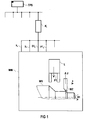
- the illustration in FIG. 1 indicates in the form of a block diagram how setpoint values for the movements of the units of a machine tool WM to be carried out are output from a part program memory TPS via a channel K i of the control, via a channel K i of the control.
- the machine tool WM may be a lathe in which a workpiece WS is rotated about an axis S1 and a tool WZ, in this case a turning tool, is positioned in two axes x and y.
- the setpoints for the movements of the axes S1, x and y are supplied via the numerical control as values x s , y s and S1 s from the same channel K i , which then also sets setpoints P1 s for the position P1 of a loader L, in the it may be a tool loader.
- additional axis information can also be provided by the numerical control to the machine tool WM, as is indicated by open outputs on the channel K i .
- the open network behind the part program memory TPS and the channel K i should indicate that other channels of numerical control are also available for other control purposes.
- the kinematically coupled main axes x and y are moved in accordance with the information in block N10 at speed "1000" so that the values X100 and Y100 are reached. When these values are reached, the speed can be reduced, but does not have to be. It is typical, however, that when the desired position of the main axes of the block N10 is reached, the next new block N20 is started immediately. This is indicated by an arrow in the illustration.
- the positioning axis P1 will continue to be moved in the following until the assigned position "50" is reached and can then be stopped.
- FIG 3 shows a further exemplary embodiment shown, which is essentially the embodiment 2 corresponds, but here the case is assumed that block N20 should only be started when both the movement of the main axes in block N10 as well as the movement the positioning axis in block N10 has been completed.
- a POS criterion instead of the POS A criterion. This is detected and evaluated in the control system in such a way that before the start of such an additional criterion next sentence, i.e. in this case the sentence N20, initially the movement of the positioning axis P1 must have ended. First then, if the movements of Main axes and positioning axes are completed the next block of the part program, in this case the block N20 started. This fact is also due to one Arrow indicated on the time axis in the lower part of FIG 3.
Landscapes
- Engineering & Computer Science (AREA)
- Human Computer Interaction (AREA)
- Manufacturing & Machinery (AREA)
- Physics & Mathematics (AREA)
- General Physics & Mathematics (AREA)
- Automation & Control Theory (AREA)
- Computer Hardware Design (AREA)
- Microelectronics & Electronic Packaging (AREA)
- Numerical Control (AREA)
Abstract
Description
Die Erfindung bezieht sich auf ein Verfahren zum Betrieb einer Werkzeugmaschine oder eines Roboters mit unmittelbar zusammenwirkenden Hauptachsen sowie zusätzlichen Positionierachsen, wobei alle Achsen von einer numerischen Steuerung entsprechend einem satzweise gegliederten Teileprogramm mit Sollwerten für die auszuführenden Bewegungen versorgt werden.The invention relates to a method of operation a machine tool or a robot with immediate interacting main axes as well as additional positioning axes, where all axes from a numerical control according to a parts program structured in blocks Setpoints for the movements to be executed are supplied.
Bei modernen Werkzeugmaschinen ist es nicht nur erforderlich, die Hauptachsen zu steuern, sondern es sind auch weitere Achsen, sogenannte Positionierachsen, zu berücksichtigen. Positionierachsen stellen eine Möglichkeit zur Programmierung paralleler Bewegungsvorgänge dar. Damit ist es also möglich, mindestens eine zweite Bewegung zur Werkzeug- und Werkstückhandhabung während der Hauptzeit auszuführen. Beispielhafte Anwendungsgebiete hierzu sind:
- Starten des Bewegungsvorganges eines Laders zur Werkstückentnahme bevor die Rückzugsbewegung des Werkzeugs auf eine sichere Position zum Stillstand gebracht würde,
- Steuerung einer Pinole,
- Positionierung eines neu einzuwechselnden Werkzeugs auf eine Werkzeugwechselposition parallel zum Bearbeitungsvorgang.
- Starting the movement process of a loader for workpiece removal before the retraction movement of the tool would be brought to a safe position,
- Control of a quill,
- Positioning of a new tool to be changed to a tool change position parallel to the machining process.
Bei mehrkanaligen Werkzeugmaschinensteuerungen war die Berücksichtigung von Positionierachsen bis dato nur möglich, wenn Haupt- und Positionierachsen in unterschiedlichen Kanälen gesteuert wurden (DE-OS 43 33 201). Dabei wurde der zeitliche Ablauf von Positionier- und Hauptachsen durch eine Anpaßsteuerung, eine sogenannte PLC, gesteuert bzw. synchronisiert. Eine Synchronisierung von Positionier- und Hauptachsen im selben Interpolationstakt war dabei nicht möglich. For multi-channel machine tool controls that was To date, positioning axes have only been possible, if the main and positioning axes are in different channels were controlled (DE-OS 43 33 201). The Timing of positioning and main axes by one Adaptation control, a so-called PLC, controlled or synchronized. A synchronization of positioning and main axes it was not possible in the same interpolation cycle.
Aufgabe der Erfindung ist es, ein Verfahren der eingangs genannten Art so auszubilden, daß sowohl Hauptachsen, als auch Positionierachsen gemeinsam programmiert werden können und nicht in mehreren Kanälen entkoppelt voneinander zu behandeln sind.The object of the invention is a method of the aforementioned Kind so that both main axes, as well Positioning axes can be programmed together and not to be treated separately from one another in several channels are.
Gemäß der Erfindung wird diese Aufgabe dadurch gelöst, daß jeweils in einem Satz des Teileprogramms sowohl die Hauptachsen als auch die Positionierachsen entsprechend vorgegebener Parameter gestartet werden, daß dabei jedoch ein Zusatzkriterium für die jeweiligen Positionierachsen vergeben wird, das angibt, ob der nächste Satz des Teileprogramms ablaufen darf, wenn der vorangegangene Satz nur für die Hauptachsen abgearbeitet ist und die Positionierachsen gegebenenfalls noch die in diesem Satz gestarteten Bewegungen ausführen oder wenn der vorangegangene Satz sowohl für die Hauptachsen als auch für die Positionierachsen abgearbeitet ist.According to the invention, this object is achieved in that Both the main axes in one block of the part program as well as the positioning axes according to specified Parameters are started, but this is an additional criterion assigned for the respective positioning axes which indicates whether the next block of the part program may run if the previous sentence is only for the Main axes are processed and the positioning axes if necessary nor the movements started in this sentence execute or if the previous sentence for both the Main axes as well as for the positioning axes is.
Dadurch, daß ein gemeinsamer Interpolationstakt (IPO-Takt) zum Generieren der Sollwerte für die Hauptachsen und die Positionierachsen verwendet wird, ist eine Synchronisierung von Positionier- und Hauptachsen im selben IPO-Takt möglich.The fact that a common interpolation clock (IPO clock) to generate the setpoints for the main axes and the Positioning axes is used is a synchronization of positioning and main axes possible in the same IPO cycle.
Bedarfsweise können jedoch auch verschiedene Interpolationstakte zum Generieren der Sollwerte für die Hauptachsen und die Positionierachsen verwendet werden.If necessary, however, different interpolation cycles can also be used to generate the setpoints for the main axes and the positioning axes are used.
Ein Ausführungsbeispiel der Erfindung ist in der Zeichnung dargestellt und wird im folgenden näher erläutert. Dabei zeigen:
- FIG 1
- die Struktur des Zusammenspiels einer numerischen Steuerung mit einer Werkzeugmaschine,
- FIG 2
- ein erstes Teileprogramm mit resultierendem Zeit-Geschwindigkeitsverlauf und
- FIG 3
- ein zweites Teileprogramm mit resultierendem Zeit-Geschwindigkeitsverlauf.
- FIG. 1
- the structure of the interaction of a numerical control with a machine tool,
- FIG 2
- a first part program with the resulting time-speed curve and
- FIG 3
- a second part program with the resulting time-speed curve.
In der Darstellung gemäß FIG 1 ist in Form eines Blockschaltbildes angedeutet, wie aus einem Teileprogrammspeicher TPS einer der Übersichtlichkeit halber nicht weiter dargestellten numerischen Steuerung über einen Kanal Ki der Steuerung Sollwerte für die auszuführenden Bewegungen der Aggregate einer Werkzeugmaschine WM ausgegeben werden. Bei der Werkzeugmaschine WM mag es sich dabei um eine Drehmaschine handeln, bei der ein Werkstück WS um eine Achse S1 gedreht wird und wobei ein Werkzeug WZ, in diesem Fall ein Drehmeißel, in zwei Achsen x und y positioniert wird. Die Sollwerte für die Bewegungen der Achsen S1, x und y werden über die numerische Steuerung als Werte xs, ys und S1s aus demselben Kanal Ki geliefert, der dann auch Sollwerte P1s für die Position P1 eines Laders L, bei den es sich um einen Werkzeuglader handeln möge, liefert. Selbstverständlich können noch weitere Achsinformationen von der numerischen Steuerung an die Werkzeugmaschine WM gegeben werden, wie dies durch offene Ausgänge am Kanal Ki angedeutet ist. Ebenso soll das offene Netzwerk hinter dem Teileprogrammspeicher TPS und den Kanal Ki darauf hindeuten, daß auch weitere Kanäle der numerischen Steuerung für andere Steuerungszwecke zur Verfügung stehen.The illustration in FIG. 1 indicates in the form of a block diagram how setpoint values for the movements of the units of a machine tool WM to be carried out are output from a part program memory TPS via a channel K i of the control, via a channel K i of the control. The machine tool WM may be a lathe in which a workpiece WS is rotated about an axis S1 and a tool WZ, in this case a turning tool, is positioned in two axes x and y. The setpoints for the movements of the axes S1, x and y are supplied via the numerical control as values x s , y s and S1 s from the same channel K i , which then also sets setpoints P1 s for the position P1 of a loader L, in the it may be a tool loader. Of course, additional axis information can also be provided by the numerical control to the machine tool WM, as is indicated by open outputs on the channel K i . Likewise, the open network behind the part program memory TPS and the channel K i should indicate that other channels of numerical control are also available for other control purposes.
Zunächst sei angenommen, daß der Wunsch bestehen möge, daß zwar die Hauptachsen x und y wie auch die Positionierachse P1 gemeinsam gestartet werden, daß jedoch dann unverzüglich nach Beendigung der ausgelösten Bewegungen für die Hauptachsen der nächsten Satz des Programms fortgeführt werden kann, ohne daß zuerst die Beendigung der Bewegung der Positionierachse P1 abzuwarten wäre.First of all, it is assumed that there may be a wish that the main axes x and y as well as the positioning axis P 1 are started together, but that the next block of the program can then be continued immediately after the triggered movements for the main axes have ended, without first wait for the movement of the positioning axis P1 to end.
Programmtechnisch könnte das, wie im oberen Teil von FIG 2 angedeutet, so aussehen, daß in einem ersten Satz N10 zunächst mit der Kennung G01 angegeben wird, daß eine Linearbewegung der Hauptachsen erfolgen soll. Durch die Parameter X100 und Y100 wird die anzufahrende Position angegeben und mit F1000 wird die Geschwindigkeit der Bewegung definiert. In diesem Satz N10 wird jedoch nun ein Zusatzkriterium eingeführt, das im Beispiel als POS A angibt, daß die im folgenden spezifizierte Positionierachse P1 zwar mit dem Satz N10 gestartet wird, jedoch unabhängig von der weiteren Programmabfolge weiterbewegt wird, bis ein durch POS A [P1] = 50 definierter Ort "50" der Positionierachse P1 erreicht ist. Durch F[P1] = 2000 wird die Geschwindigkeit der Positionierachsbewegung definiert.In terms of programming, this could, as in the upper part of FIG indicated, look like that in a first sentence N10 initially with the identifier G01 indicates that a linear movement of the main axes. By the parameters X100 and Y100 indicate the position to be approached and the speed of movement is defined with F1000. In However, an additional criterion is now introduced in this sentence N10, which indicates in the example as POS A that the following specified positioning axis P1 started with block N10 will, however, regardless of the further program sequence is continued until one through POS A [P1] = 50 Defined location "50" of the positioning axis P1 is reached. With F [P1] = 2000 the speed of the positioning axis movement Are defined.
In einem nächsten Satz des Teileprogramms, d.h. im Ausführungsbeispiel einem Satz N20, kann dann angegeben sein., daß durch eine weitere Linearbewegung mit gleichbleibender Geschwindigkeit die Hauptachsen x und y auf Werte X200 und Y200 zu verfahren sind.In a next block of the part program, i.e. in the embodiment a sentence N20, it can then be stated that by a further linear movement with constant speed the main axes x and y to values X200 and Y200 are to be followed.
Der resultierende Zeit-Geschwindigkeitsverlauf v = f(t) ist im unteren Teil von FIG 2 dargestellt. So ist ersichtlich, daß zur Zeit t0 sowohl die Bewegungen der Hauptachsen x, y als auch der Positionierachse P1 gestartet werden. Die kinematisch gekoppelten Hauptachsen x und y werden gemäß der Information des Satzes N10 mit Geschwindigkeit "1000" so bewegt, daß die Werte X100 und Y100 erreicht werden. Bei Erreichen dieser Werte kann - aber muß nicht - eine Geschwindigkeitsabsenkung vorgenommen werden. Typisch ist jedoch, daß mit dem Erreichen der angestrebten Position der Hauptachsen des Satzes N10 unverzüglich der nächste neue Satz N20 gestartet wird. Dies ist in der Darstellung durch einen Pfeil angedeutet. Die Positionierachse P1 wird nun im folgenden solange weiterverfahren, bis die dort angestrebte zugewiesene Position "50" erreicht ist und kann dann stillgesetzt werden. The resulting time-velocity curve v = f (t) is shown in the lower part of FIG. 2. It can thus be seen that both the movements of the main axes x, y and the positioning axis P1 are started at time t 0 . The kinematically coupled main axes x and y are moved in accordance with the information in block N10 at speed "1000" so that the values X100 and Y100 are reached. When these values are reached, the speed can be reduced, but does not have to be. It is typical, however, that when the desired position of the main axes of the block N10 is reached, the next new block N20 is started immediately. This is indicated by an arrow in the illustration. The positioning axis P1 will continue to be moved in the following until the assigned position "50" is reached and can then be stopped.
In der Darstellung gemäß FIG 3 ist ein weiteres Ausführungsbeispiel gezeigt, das im wesentlichen dem Ausführungsbeispiel gemäß FIG 2 entspricht, jedoch ist hier der Fall angenommen, daß der Satz N20 erst dann gestartet werden soll, wenn sowohl die Bewegung der Hauptachsen im Satz N10 als auch die Bewegung der Positionierachse im Satz N10 abgeschlossen ist. Dazu entspricht die zugehörige Programmierung zwar in fast allen Schritten der obengenannten Programmierung, jedoch wird dabei anstelle des Kriteriums POS A ein Kriterium POS verwendet. Dies wird in der Steuerung so detektiert und ausgewertet, daß vor Start des einem solchen Zusatzkriteriums folgenden nächsten Satzes, d.h. in diesem Fall des Satzes N20, zunächst die Bewegung der Positionierachse P1 beendet sein muß. Erst dann, wenn also die im Satz N10 ausgelösten Bewegungen von Hauptachsen und Positionierachsen abgeschlossen sind, wird der nächste Satz des Teileprogramms, in diesem Fall der Satz N20, gestartet. Dieser Sachverhalt ist ebenfalls durch einen Pfeil auf der Zeitachse im unteren Teil von FIG 3 angedeutet.3 shows a further exemplary embodiment shown, which is essentially the embodiment 2 corresponds, but here the case is assumed that block N20 should only be started when both the movement of the main axes in block N10 as well as the movement the positioning axis in block N10 has been completed. To the corresponding programming corresponds in almost all Steps of the above programming, however uses a POS criterion instead of the POS A criterion. This is detected and evaluated in the control system in such a way that before the start of such an additional criterion next sentence, i.e. in this case the sentence N20, initially the movement of the positioning axis P1 must have ended. First then, if the movements of Main axes and positioning axes are completed the next block of the part program, in this case the block N20 started. This fact is also due to one Arrow indicated on the time axis in the lower part of FIG 3.
Claims (3)
- Method for operating a machine tool (WM) or a robot having directly interacting main axes (x, y, S1) and also additional positioning axes (P1), wherein all of the axes (x, y, S1, P1) are supplied, by a numerical control in accordance with a subprogram organised in blocks, with setpoints (xs, ys, S1s, P1s) for the movements to be carried out, wherein in each case in a block (N10) of the subprogram, both the main axes (x, y) and the positioning axes (P1) are started in accordance with predetermined parameters, in which case, however, an additional criterion (POS A or POS) is given for the respective positioning axes (P1), which additional criterion indicates whether the next block (N20) of the subprogram may run if the previous block has been processed only for the main axes and the positioning axes are possibly still carrying out the movements started in this block or if the previous block has been processed both for the main axes and for the positioning axes.
- Method according to claim 1, characterised in that a common interpolation cycle is used for generating the setpoints for the main axes and the positioning axes.
- Method according to claim 1, characterised in that different interpolation cycles are used for generating the setpoints for the main axes and the positioning axes.
Applications Claiming Priority (2)
| Application Number | Priority Date | Filing Date | Title |
|---|---|---|---|
| DE19512173 | 1995-03-31 | ||
| DE19512173 | 1995-03-31 |
Publications (3)
| Publication Number | Publication Date |
|---|---|
| EP0735444A2 EP0735444A2 (en) | 1996-10-02 |
| EP0735444A3 EP0735444A3 (en) | 1998-04-22 |
| EP0735444B1 true EP0735444B1 (en) | 2000-06-07 |
Family
ID=7758485
Family Applications (1)
| Application Number | Title | Priority Date | Filing Date |
|---|---|---|---|
| EP96104811A Expired - Lifetime EP0735444B1 (en) | 1995-03-31 | 1996-03-26 | Method for operating a machine tool or a robot with directly interacting main axles and additional positioning axles |
Country Status (3)
| Country | Link |
|---|---|
| EP (1) | EP0735444B1 (en) |
| AT (1) | ATE193772T1 (en) |
| DE (1) | DE59605379D1 (en) |
Families Citing this family (3)
| Publication number | Priority date | Publication date | Assignee | Title |
|---|---|---|---|---|
| US6625498B1 (en) | 1999-05-11 | 2003-09-23 | Fanuc Ltd. | Numerical control system |
| DE10017775A1 (en) * | 2000-04-10 | 2001-10-18 | Siemens Ag | Input method for programming industrial controls |
| US7000191B2 (en) | 2000-08-07 | 2006-02-14 | Siemens Aktiengesellschaft | Flowchart programming for industrial controllers, in particular motion controllers |
Family Cites Families (2)
| Publication number | Priority date | Publication date | Assignee | Title |
|---|---|---|---|---|
| JPS59216205A (en) * | 1983-05-23 | 1984-12-06 | Mitsubishi Electric Corp | Numerical control device |
| DE4333201A1 (en) * | 1993-09-29 | 1995-03-30 | Siemens Ag | Device for controlling a multiaxis machine tool or a robot |
-
1996
- 1996-03-26 AT AT96104811T patent/ATE193772T1/en not_active IP Right Cessation
- 1996-03-26 EP EP96104811A patent/EP0735444B1/en not_active Expired - Lifetime
- 1996-03-26 DE DE59605379T patent/DE59605379D1/en not_active Expired - Lifetime
Also Published As
| Publication number | Publication date |
|---|---|
| ATE193772T1 (en) | 2000-06-15 |
| DE59605379D1 (en) | 2000-07-13 |
| EP0735444A3 (en) | 1998-04-22 |
| EP0735444A2 (en) | 1996-10-02 |
Similar Documents
| Publication | Publication Date | Title |
|---|---|---|
| DE69330144T2 (en) | Numerically controlled machine tool | |
| DE3806966C2 (en) | ||
| EP0120204B1 (en) | Method for rerunning a tool against a contour of a workpiece | |
| DE102016103440A1 (en) | Control device that can centrally manage a controller by grouping multiple systems | |
| DE69126332T2 (en) | Automatic programming device for a numerically controlled machine with multiple spindles | |
| DE1966794B2 (en) | Device for the numerical control of machine tools by means of a central data processing system | |
| EP1217483B1 (en) | Processing device and control program of machining | |
| EP0543034B1 (en) | Process for operation of numerical controlled machine tool and machine tool for implementation of the process | |
| DE69727461T2 (en) | OVERLAY CONTROL METHOD WITH NUMERICAL CONTROL | |
| EP0706103A1 (en) | Method and device for numerical control of path for machine-tools or robots | |
| DE2338880A1 (en) | METHODS AND DEVICES FOR CONTROLLING THE MOVING PARTS OF A MACHINE TOOL THROUGH A NUMERICAL OUTLINE OR POINT-BY-POINT CONTROL SYSTEM, WHEREAS TWO PARTS OF THE MACHINE INDEPENDENTLY SEPARATE | |
| DE10343809B4 (en) | Method and apparatus for numerical control | |
| EP4246257A1 (en) | Speed dependent overgrinding between sets with discontinuous courses | |
| EP0735444B1 (en) | Method for operating a machine tool or a robot with directly interacting main axles and additional positioning axles | |
| DE10255033A1 (en) | Machine tool and method for operating such | |
| DE3902460C2 (en) | ||
| DE68926442T2 (en) | Robot control system for controlling a variety of industrial robots | |
| DE102020202854A1 (en) | NUMERICAL CONTROL SYSTEM FOR A MACHINE TOOL | |
| EP0735445B1 (en) | Method for the operation of a machine-tool or a robot | |
| EP1025469A1 (en) | Method for controlling a cnc machine tool | |
| DE102017011602A1 (en) | Numerical control | |
| DE10308815B4 (en) | Method for generating and visualizing a task-oriented step representation | |
| DE4126434A1 (en) | NUMERIC CONTROL DEVICE | |
| DE4330469C2 (en) | Method for controlling a machine tool with multiple slides | |
| DE3545957A1 (en) | Method and circuit arrangement for automatically processing setting-up functions in numeric controls |
Legal Events
| Date | Code | Title | Description |
|---|---|---|---|
| PUAI | Public reference made under article 153(3) epc to a published international application that has entered the european phase |
Free format text: ORIGINAL CODE: 0009012 |
|
| AK | Designated contracting states |
Kind code of ref document: A2 Designated state(s): AT CH DE ES FR GB IT LI SE |
|
| PUAL | Search report despatched |
Free format text: ORIGINAL CODE: 0009013 |
|
| AK | Designated contracting states |
Kind code of ref document: A3 Designated state(s): AT CH DE ES FR GB IT LI SE |
|
| 17P | Request for examination filed |
Effective date: 19980519 |
|
| 17Q | First examination report despatched |
Effective date: 19980825 |
|
| GRAG | Despatch of communication of intention to grant |
Free format text: ORIGINAL CODE: EPIDOS AGRA |
|
| GRAG | Despatch of communication of intention to grant |
Free format text: ORIGINAL CODE: EPIDOS AGRA |
|
| GRAH | Despatch of communication of intention to grant a patent |
Free format text: ORIGINAL CODE: EPIDOS IGRA |
|
| GRAH | Despatch of communication of intention to grant a patent |
Free format text: ORIGINAL CODE: EPIDOS IGRA |
|
| GRAA | (expected) grant |
Free format text: ORIGINAL CODE: 0009210 |
|
| AK | Designated contracting states |
Kind code of ref document: B1 Designated state(s): AT CH DE ES FR GB IT LI SE |
|
| PG25 | Lapsed in a contracting state [announced via postgrant information from national office to epo] |
Ref country code: IT Free format text: LAPSE BECAUSE OF FAILURE TO SUBMIT A TRANSLATION OF THE DESCRIPTION OR TO PAY THE FEE WITHIN THE PRESCRIBED TIME-LIMIT;WARNING: LAPSES OF ITALIAN PATENTS WITH EFFECTIVE DATE BEFORE 2007 MAY HAVE OCCURRED AT ANY TIME BEFORE 2007. THE CORRECT EFFECTIVE DATE MAY BE DIFFERENT FROM THE ONE RECORDED. Effective date: 20000607 Ref country code: GB Free format text: LAPSE BECAUSE OF FAILURE TO SUBMIT A TRANSLATION OF THE DESCRIPTION OR TO PAY THE FEE WITHIN THE PRESCRIBED TIME-LIMIT Effective date: 20000607 Ref country code: FR Free format text: LAPSE BECAUSE OF FAILURE TO SUBMIT A TRANSLATION OF THE DESCRIPTION OR TO PAY THE FEE WITHIN THE PRESCRIBED TIME-LIMIT Effective date: 20000607 Ref country code: ES Free format text: THE PATENT HAS BEEN ANNULLED BY A DECISION OF A NATIONAL AUTHORITY Effective date: 20000607 |
|
| REF | Corresponds to: |
Ref document number: 193772 Country of ref document: AT Date of ref document: 20000615 Kind code of ref document: T |
|
| REG | Reference to a national code |
Ref country code: CH Ref legal event code: EP |
|
| REF | Corresponds to: |
Ref document number: 59605379 Country of ref document: DE Date of ref document: 20000713 |
|
| PG25 | Lapsed in a contracting state [announced via postgrant information from national office to epo] |
Ref country code: SE Free format text: LAPSE BECAUSE OF FAILURE TO SUBMIT A TRANSLATION OF THE DESCRIPTION OR TO PAY THE FEE WITHIN THE PRESCRIBED TIME-LIMIT Effective date: 20000907 |
|
| EN | Fr: translation not filed | ||
| GBV | Gb: ep patent (uk) treated as always having been void in accordance with gb section 77(7)/1977 [no translation filed] |
Effective date: 20000607 |
|
| PG25 | Lapsed in a contracting state [announced via postgrant information from national office to epo] |
Ref country code: AT Free format text: LAPSE BECAUSE OF NON-PAYMENT OF DUE FEES Effective date: 20010326 |
|
| PG25 | Lapsed in a contracting state [announced via postgrant information from national office to epo] |
Ref country code: LI Free format text: LAPSE BECAUSE OF NON-PAYMENT OF DUE FEES Effective date: 20010331 Ref country code: CH Free format text: LAPSE BECAUSE OF NON-PAYMENT OF DUE FEES Effective date: 20010331 |
|
| PLBE | No opposition filed within time limit |
Free format text: ORIGINAL CODE: 0009261 |
|
| STAA | Information on the status of an ep patent application or granted ep patent |
Free format text: STATUS: NO OPPOSITION FILED WITHIN TIME LIMIT |
|
| 26N | No opposition filed | ||
| REG | Reference to a national code |
Ref country code: CH Ref legal event code: PL |
|
| PG25 | Lapsed in a contracting state [announced via postgrant information from national office to epo] |
Ref country code: DE Free format text: LAPSE BECAUSE OF NON-PAYMENT OF DUE FEES Effective date: 20111001 |
|
| PGFP | Annual fee paid to national office [announced via postgrant information from national office to epo] |
Ref country code: DE Payment date: 20150513 Year of fee payment: 20 |
|
| REG | Reference to a national code |
Ref country code: DE Ref legal event code: R071 Ref document number: 59605379 Country of ref document: DE |