EP0734992B1 - Servo control for hydraulic elevator - Google Patents
Servo control for hydraulic elevator Download PDFInfo
- Publication number
- EP0734992B1 EP0734992B1 EP19950108237 EP95108237A EP0734992B1 EP 0734992 B1 EP0734992 B1 EP 0734992B1 EP 19950108237 EP19950108237 EP 19950108237 EP 95108237 A EP95108237 A EP 95108237A EP 0734992 B1 EP0734992 B1 EP 0734992B1
- Authority
- EP
- European Patent Office
- Prior art keywords
- valve
- flow
- elevator
- spool
- solenoid valve
- Prior art date
- Legal status (The legal status is an assumption and is not a legal conclusion. Google has not performed a legal analysis and makes no representation as to the accuracy of the status listed.)
- Expired - Lifetime
Links
Images
Classifications
-
- G—PHYSICS
- G05—CONTROLLING; REGULATING
- G05D—SYSTEMS FOR CONTROLLING OR REGULATING NON-ELECTRIC VARIABLES
- G05D7/00—Control of flow
- G05D7/06—Control of flow characterised by the use of electric means
- G05D7/0617—Control of flow characterised by the use of electric means specially adapted for fluid materials
- G05D7/0623—Control of flow characterised by the use of electric means specially adapted for fluid materials characterised by the set value given to the control element
-
- B—PERFORMING OPERATIONS; TRANSPORTING
- B66—HOISTING; LIFTING; HAULING
- B66B—ELEVATORS; ESCALATORS OR MOVING WALKWAYS
- B66B1/00—Control systems of elevators in general
- B66B1/24—Control systems with regulation, i.e. with retroactive action, for influencing travelling speed, acceleration, or deceleration
- B66B1/26—Control systems with regulation, i.e. with retroactive action, for influencing travelling speed, acceleration, or deceleration mechanical
-
- Y—GENERAL TAGGING OF NEW TECHNOLOGICAL DEVELOPMENTS; GENERAL TAGGING OF CROSS-SECTIONAL TECHNOLOGIES SPANNING OVER SEVERAL SECTIONS OF THE IPC; TECHNICAL SUBJECTS COVERED BY FORMER USPC CROSS-REFERENCE ART COLLECTIONS [XRACs] AND DIGESTS
- Y10—TECHNICAL SUBJECTS COVERED BY FORMER USPC
- Y10T—TECHNICAL SUBJECTS COVERED BY FORMER US CLASSIFICATION
- Y10T137/00—Fluid handling
- Y10T137/2496—Self-proportioning or correlating systems
- Y10T137/2559—Self-controlled branched flow systems
- Y10T137/2574—Bypass or relief controlled by main line fluid condition
- Y10T137/2579—Flow rate responsive
- Y10T137/2589—Pilot valve operated
Definitions
- This invention relates to a hydraulic elevator control system comprising a flow channel sensing device.
- Hydraulic elevators should approach their scheduled stopping positions gently and accurately. To establish alignment of the bottom of an elevator and a storey floor when stopping following an upward travel, the stopping point is approached from below at a creeping speed of travel during the final stage of approach.
- Known valves employing hydraulic mechanical methods of speed control are to varying degrees load and viscosity dependent. Such valves, correctly designed, offer a high degree of reliability combined with good ride qualities, but are not suitable for remote, or self re-adjustment.
- Such a drive control system for a hydraulic elevator is described in GB-A-1 378 345.
- the system comprises a check valve interposed in a pipe between a source of pressurized fluid and and an elevator cylinder, and a circulating or bypass valve interposed between the source of pressurized fluid and an oil collection vessel.
- the circulating or bypass valve is biased in a direction of opening thereof and has a chamber connected to the source of pressurized fluid through a restrictor and to the oil collection vessel through a two-position valve.
- a setting valve operates as a function of the position of a sealing element of the check valve.
- the setting valve has a setting element which is directly connected to said sealing element, whereby a displacement of the sealing element produces an equal displacement of the setting element.
- the check valve is urged towards a closed position by a compression spring in conventional manner and opened to a greater or lesser extent depending on the volume of through-flow.
- a stroke performed by the check valve provides a parameter for controlling the circulating valve.
- the required volume of fluid governing the opening of the check valve is ducted to the elevator cylinder on the one hand, and on the other hand the total quantity of unnecessary fluid complementarily delivered by a source of pressurized fluid, such as a pump, goes back to the oil storage container through the circulating valve.
- a source of pressurized fluid such as a pump
- US-A-5 212 951 refers to an elevator system comprising an elevator car, a plunger, a hydraulic cylinder, a valve and a conventional variable speed, reversible motor and a pump.
- the pump and the motor are disposed within a tank which is filled with hydraulic fluid.
- the motor powers the pump to provide a fluid pressure force to raise and lower the elevator.
- the system may include a pressure relief valve and a manual lowering valve.
- the valve comprises a housing, a check valve, a solenoid valve and an activation assembly. The valve is disposed in a line passing fluid between the variable speed pump and the cylinder.
- the fluid pressure force from the pump acts upon one side of the valve.
- the fluid pressure force of fluid in the cylinder acts upon the other side of the valve.
- the solenoid valve is provided to control a separate circuit on the pump side of the valve. This separate circuit directs the pump fluid pressure force behind the valve until the sum of the fluid pressure acting on the pump side of the valve overcomes the fluid pressure on the cylinder side of the valve to open the valve.
- the check valve comprises a frustoconical portion connected with the activation assembly and cooperates with the seat of a valve chamber provided in the housing.
- a position sensor extending into the valve chamber abuts the frustoconical portion when seated against the seat.
- a computer is provided for controlling the solenoid valve in the variable speed motor. Once the valve is opened, the position sensor alerts the computer that the variable speed motor may be controlled to follow a chosen speed profile to lower the elevator cab to a next landing. Such a profile allows the motor to gradually slow to control the downward rate of acceleration, go into reverse and then reverse again to slow the cab as it approaches the landing.
- Such an induction-type sensor serves only to alert the computer that the conically-shaped check valve is open.
- the sensor is otherwise inadequate to register the distance the check. valve is opened. Thus, a servo-controlling of the movement of the elevator is not possible.
- US-A-5 115 684 discloses a flow meter which includes a piston that is biased by a spring to a neutral position within an encircling collar.
- the piston is movable relative to the collar by and in the direction of the fluid flow to be measured.
- a movement of the piston relative to the collar increases the fluid flow through one or more slots provided in one of such components.
- a Hall device senses the movement of a magnet connected to the piston, and produces an output signal.
- a linear relationship between the output signal and the rate of flow of the fluid can be achieved by utilization of a magnetic member whose magnetic intensity or cross-sectional shape varies along its length, or by causing the magnet to move along a curve or other path of travel that varies its distance from the probe of the Hall device.
- This contactlessly operating flow meter has a constant measuring behaviour over its entire measuring range, with the output signal of the flow meter always being proportional to the rate of flow.
- this flow meter is limited to the installing of the obligatory magnet such that its movement is parallel to and of the same distance as the flow responsive piston itself. This limits the options of design for this : section of the valve.
- the magnetizing and installation of the magnet is critical and too often leads to unsatisfactory operation.
- the principle of this system can be applied to the up-travel as well as to the down-travel cycle of the hydraulic elevator.
- the larger movement of a fluid flow responsive disc can be converted to the smaller distance measuring capability of an economically available frequency inductive analogue distance measuring sensor.
- the rate of flow of fluid through the channel towards the hydraulic cylinder can be registered electronically by means of the computer for comparison with a desirable rate of flow for the purpose of initiating, where necessary, a correcting process to the rate of flow of fluid.
- the electronic flow sensor combined with the computer the distance already travelled by the elevator can be assessed in order to effect a desired speed or change of speed of the elevator in the remaining distance to be travelled for accomplishing accuracy of stop and passenger comfort. Additionally the characteristics of foregoing operations are remembered and assessed by the computer such that control signals for following operations are revised to achieve shorter travelling times or other desired characteristics of travel performance.
- overriding safety solenoids are included in the pilot channel system of the electronically controlled valve to rapidly reduce the flow of fluid in order to slow down the car in the event of uncontrolled motion in either direction of travel.
- an electric motor driving pump 11 is energized and fluid is dispatched into a pump chamber 13 of the control valve through an opening 3 of a bypass valve 2 and by way of return passage 7 and 10 back to tank 70.
- solenoid valves 22 and 25 are energized.
- Solenoid 22 is a normally open, open - close valve
- solenoid 25 a normally open proportional type valve through which the volume of pilot oil flowing through fixed orifice 9 to bypass valve chamber 6 is allowed to escape to tank 70 at a rate inversely proportional to the strength of the electrical signal to the coil, tending to close the solenoid valve 25.
- the strength of this electrical signal is determined by the flow sensing valve 50 which comprises a flow sensing spool 52 including a flow responsive disc 53 and a part 54 located along the axis of the spool 52 at the opposite end from the disc 53, said part 54 comprising two truncated conical members joined at their bases, at said junction said members defining an apex or peak in the longitudinal cross section of said spool 52 at which peak and at right angles to the axis of the flow sensing spool 52 a inductive analogue distance sensor 59 is situated.
- This flow sensing value 50 registers the flow rate of fluid to the cylinder 49 raising the elevator.
- the targeted movement of the flow sensing spool 52 programmed into a computer is compared with the actual movement of the flow sensing spool 52, so that the necessary correction can be calculated and the corrected electrical signal applied to the solenoid valve 25.
- the computer increases the electrical output to this solenoid valve 25, further closing it and thereby causing the pilot pressure in the bypass chamber 6 to rise and the bypass valve 2 to advance against the opening force of bypass spring 4 until pressure in the pump chamber 13 rises above the pressure in a cylinder chamber 45. At this point the elevator begins to accelerate upwards.
- the continuing up-acceleration of the elevator and all subsequent motions ' including fast speed, deceleration, slow approach speed and stopping of the elevator are monitored by the flow sensing valve 50 which relays the actual converted values of volume of fluid flowing to the cylinder 49 representing the motion of the elevator, to the computer for comparison with the target values as described above.
- Adjusting screw 5 limits the open or rest position of the bypass valve 2 and assures the initial pilot pressure in the system once the pump 11 is running.
- the flow sensing valve 50 as shown in Fig. 2 comprises a valve housing 4b having passages 45, 47 and 48, a flow ring 55 and the metal flow sensing spool 52 mounted on a shaft 56 fixed to the housing 46, the metal spool 52. being centrally positioned axially on a shaft spring 57 pressing outwards against sliding bushings 58 which press against internal shoulders 61 of the metal spool 52 and contacting shoulders 62 on the shaft 56.
- At one end of the metal spool 52 is integrated the flow responsive disc 53 fitting closely but sliding within the fixed flow ring 55. such that a flow of fluid either from passage 45 to passage 48 or reversed moves the disc 53 complete with the metal spool 52 in one direction or the other.
- the apex of the part 54 extending along the axis of the metal spool 52 on its outside diameter is centered beneath the sensing point 51 of the inductive analogue distance sensor 59 installed at right angles to the axis of the metal spool 52.
- the volume of fluid flowing through the flow sensing valve 50 determines the size of the opening forced between. disc 53 and flow ring 55 which directly affects the distance of displacement of the metal spool 52 along the shaft 56, this to a proportional degree affecting the distance between the sensing point 51 of the distance sensor 59 and the conical surface of the part 54 of the metal spool 52.
- the changing distance is registered by the distance sensor 59 and transmitted to the computer for processing.
- the up safety solenoid valve 22 (FIG. 1) remains energized. If, due to a disturbance in the computer system, an undesirable motion of the elevator occurs, such as overspeeding or oscillating, by de-energizing solenoid 22, the elevator can be immediately slowed to a mechanically regulated low speed as long as the pump 11 continues to run and solenoid 25 remains energized.
- solenoid 25 is energized at maximum power and the pump 11 activated, while the up safety solenoid 22 remains de-energized.
- variable orifice 18 which determines in which position the check valve 14 becomes hydraulically balanced and thereby the speed of the elevator, can be changed through adjusting screw 19 inwards or outwards to obtain the required slower or faster mechanical up levelling speed
- Orifice 36 in down slow speed adjusting screw 35 can be shifted in its position relative to the down valve 31 by turning the adjusting screw 35 inwards or outwards so that the hydraulically controlled down slow speed can be mechanically set as required.
- a further application of the down safety solenoid 41 is to completely stop the downwards movement of the elevator should it not be operating in the desired manner, by de-energizing the down safety coil.
- Screw 42 mechanically limits the maximum opening of the down valve and thereby the maximum possible down speed of the elevator.
Description
- This invention relates to a hydraulic elevator control system comprising a flow channel sensing device.
- Hydraulic elevators should approach their scheduled stopping positions gently and accurately. To establish alignment of the bottom of an elevator and a storey floor when stopping following an upward travel, the stopping point is approached from below at a creeping speed of travel during the final stage of approach. Known valves employing hydraulic mechanical methods of speed control are to varying degrees load and viscosity dependent. Such valves, correctly designed, offer a high degree of reliability combined with good ride qualities, but are not suitable for remote, or self re-adjustment.
- Such a drive control system for a hydraulic elevator is described in GB-A-1 378 345. The system comprises a check valve interposed in a pipe between a source of pressurized fluid and and an elevator cylinder, and a circulating or bypass valve interposed between the source of pressurized fluid and an oil collection vessel. The circulating or bypass valve is biased in a direction of opening thereof and has a chamber connected to the source of pressurized fluid through a restrictor and to the oil collection vessel through a two-position valve. A setting valve operates as a function of the position of a sealing element of the check valve. The setting valve has a setting element which is directly connected to said sealing element, whereby a displacement of the sealing element produces an equal displacement of the setting element.
- The check valve is urged towards a closed position by a compression spring in conventional manner and opened to a greater or lesser extent depending on the volume of through-flow. A stroke performed by the check valve provides a parameter for controlling the circulating valve. The required volume of fluid governing the opening of the check valve is ducted to the elevator cylinder on the one hand, and on the other hand the total quantity of unnecessary fluid complementarily delivered by a source of pressurized fluid, such as a pump, goes back to the oil storage container through the circulating valve. Upon changing from full speed to creeping speed of travel of the elevator, the circulating valve is opened first, thereby relieving the pressure in the pump chamber. A flow passage of the check valve will be adapted to the volume of oil still flowing to the cylinder. Thus, forcible closing of the check valve is eliminated.
- US-A-5 212 951 refers to an elevator system comprising an elevator car, a plunger, a hydraulic cylinder, a valve and a conventional variable speed, reversible motor and a pump. The pump and the motor are disposed within a tank which is filled with hydraulic fluid. The motor powers the pump to provide a fluid pressure force to raise and lower the elevator. The system may include a pressure relief valve and a manual lowering valve. The valve comprises a housing, a check valve, a solenoid valve and an activation assembly. The valve is disposed in a line passing fluid between the variable speed pump and the cylinder.
- The fluid pressure force from the pump acts upon one side of the valve. The fluid pressure force of fluid in the cylinder acts upon the other side of the valve. The solenoid valve is provided to control a separate circuit on the pump side of the valve. This separate circuit directs the pump fluid pressure force behind the valve until the sum of the fluid pressure acting on the pump side of the valve overcomes the fluid pressure on the cylinder side of the valve to open the valve. By balancing the pressure on the valve on the pump and cylinder sides of the valve before opening the valve, the elevator cab may start to descend gently and safely.
- The check valve comprises a frustoconical portion connected with the activation assembly and cooperates with the seat of a valve chamber provided in the housing. A position sensor extending into the valve chamber abuts the frustoconical portion when seated against the seat. A computer is provided for controlling the solenoid valve in the variable speed motor. Once the valve is opened, the position sensor alerts the computer that the variable speed motor may be controlled to follow a chosen speed profile to lower the elevator cab to a next landing. Such a profile allows the motor to gradually slow to control the downward rate of acceleration, go into reverse and then reverse again to slow the cab as it approaches the landing.
- Such an induction-type sensor serves only to alert the computer that the conically-shaped check valve is open. The sensor is otherwise inadequate to register the distance the check. valve is opened. Thus, a servo-controlling of the movement of the elevator is not possible.
- In recent years there has been a demand on some installations for more consistent traveling times between floor levels. Attempts have been made to meet such demand with computer controls. This has not, however, added to the reliability of operation of the elevator. On the contrary, experience so far has shown that where the principles of computer control to achieve the new demand are employed, problems and call backs have been more frequent than with the mechanical valve.
- In addition, the efficiency of those electronic servo valves on the market is relatively low. This is due to the excessive pressure drop through the flow rate measuring system of the valve during up travel or to fluid being bypassed in order to avoid an unstable condition arising when the target speed fed into the electronic program cannot be attained because of mechanical limits, such as the maximum output of the pump having already been reached.
- US-A-5 115 684 discloses a flow meter which includes a piston that is biased by a spring to a neutral position within an encircling collar. The piston is movable relative to the collar by and in the direction of the fluid flow to be measured. A movement of the piston relative to the collar increases the fluid flow through one or more slots provided in one of such components. A Hall device senses the movement of a magnet connected to the piston, and produces an output signal. A linear relationship between the output signal and the rate of flow of the fluid can be achieved by utilization of a magnetic member whose magnetic intensity or cross-sectional shape varies along its length, or by causing the magnet to move along a curve or other path of travel that varies its distance from the probe of the Hall device.
- This contactlessly operating flow meter has a constant measuring behaviour over its entire measuring range, with the output signal of the flow meter always being proportional to the rate of flow. However, this flow meter is limited to the installing of the obligatory magnet such that its movement is parallel to and of the same distance as the flow responsive piston itself. This limits the options of design for this : section of the valve. In addition, the magnetizing and installation of the magnet is critical and too often leads to unsatisfactory operation.
- It is the object of the invention to provide a control system of a hydraulic elevator comprising a flow channel sensing device which system reliably provides a selectable variety of smooth and accurate travel characteristics of the hydraulic elevator using a minimum of electrical energy.
- This object is achieved by the hydraulic elevator control system as defined in claim 1.
- The principle of this system can be applied to the up-travel as well as to the down-travel cycle of the hydraulic elevator.
- With the system according to the invention the larger movement of a fluid flow responsive disc can be converted to the smaller distance measuring capability of an economically available frequency inductive analogue distance measuring sensor. The rate of flow of fluid through the channel towards the hydraulic cylinder can be registered electronically by means of the computer for comparison with a desirable rate of flow for the purpose of initiating, where necessary, a correcting process to the rate of flow of fluid. Further, by employing the electronic flow sensor combined with the computer, the distance already travelled by the elevator can be assessed in order to effect a desired speed or change of speed of the elevator in the remaining distance to be travelled for accomplishing accuracy of stop and passenger comfort. Additionally the characteristics of foregoing operations are remembered and assessed by the computer such that control signals for following operations are revised to achieve shorter travelling times or other desired characteristics of travel performance.
- With the system according to
claims 3 to 6, overriding safety solenoids are included in the pilot channel system of the electronically controlled valve to rapidly reduce the flow of fluid in order to slow down the car in the event of uncontrolled motion in either direction of travel. - The invention is further explained with reference to the accompanying drawings, in which
- Fig. 1
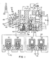
- is a schematic circuit diagram, illustrating an elevator up and down control valve comprising a flow sensing valve and
- Fig. 2
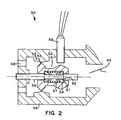
- is a sectional view of the flow sensing valve of Fig. 1.
- Referring to Fig.1, to start an upward travel of the elevator, an electric motor driving pump 11 is energized and fluid is dispatched into a
pump chamber 13 of the control valve through anopening 3 of abypass valve 2 and by way ofreturn passage tank 70. Simultaneously with the energizing of the motor,solenoid valves Solenoid 22 is a normally open, open - close valve, solenoid 25 a normally open proportional type valve through which the volume of pilot oil flowing through fixed orifice 9 to bypassvalve chamber 6 is allowed to escape totank 70 at a rate inversely proportional to the strength of the electrical signal to the coil, tending to close thesolenoid valve 25. - The strength of this electrical signal is determined by the
flow sensing valve 50 which comprises aflow sensing spool 52 including a flowresponsive disc 53 and a part 54 located along the axis of thespool 52 at the opposite end from thedisc 53, said part 54 comprising two truncated conical members joined at their bases, at said junction said members defining an apex or peak in the longitudinal cross section of saidspool 52 at which peak and at right angles to the axis of the flow sensing spool 52 a inductiveanalogue distance sensor 59 is situated. Thisflow sensing value 50 registers the flow rate of fluid to thecylinder 49 raising the elevator. The targeted movement of theflow sensing spool 52 programmed into a computer (not shown) is compared with the actual movement of theflow sensing spool 52, so that the necessary correction can be calculated and the corrected electrical signal applied to thesolenoid valve 25. Should there be no or inadequate acceleration of the elevator as programmed, the computer increases the electrical output to thissolenoid valve 25, further closing it and thereby causing the pilot pressure in thebypass chamber 6 to rise and thebypass valve 2 to advance against the opening force ofbypass spring 4 until pressure in thepump chamber 13 rises above the pressure in acylinder chamber 45. At this point the elevator begins to accelerate upwards. The continuing up-acceleration of the elevator and all subsequent motions ' including fast speed, deceleration, slow approach speed and stopping of the elevator are monitored by theflow sensing valve 50 which relays the actual converted values of volume of fluid flowing to thecylinder 49 representing the motion of the elevator, to the computer for comparison with the target values as described above. - Adjusting
screw 5 limits the open or rest position of thebypass valve 2 and assures the initial pilot pressure in the system once the pump 11 is running. - The
flow sensing valve 50 as shown in Fig. 2 comprises a valve housing4b having passages flow ring 55 and the metalflow sensing spool 52 mounted on ashaft 56 fixed to thehousing 46, themetal spool 52. being centrally positioned axially on ashaft spring 57 pressing outwards against slidingbushings 58 which press againstinternal shoulders 61 of themetal spool 52 and contactingshoulders 62 on theshaft 56. At one end of themetal spool 52 is integrated the flowresponsive disc 53 fitting closely but sliding within the fixedflow ring 55. such that a flow of fluid either frompassage 45 topassage 48 or reversed moves thedisc 53 complete with themetal spool 52 in one direction or the other. The apex of the part 54 extending along the axis of themetal spool 52 on its outside diameter is centered beneath thesensing point 51 of the inductiveanalogue distance sensor 59 installed at right angles to the axis of themetal spool 52. - The volume of fluid flowing through the
flow sensing valve 50 determines the size of the opening forced between.disc 53 andflow ring 55 which directly affects the distance of displacement of themetal spool 52 along theshaft 56, this to a proportional degree affecting the distance between thesensing point 51 of thedistance sensor 59 and the conical surface of the part 54 of themetal spool 52. The changing distance is registered by thedistance sensor 59 and transmitted to the computer for processing. - Throughout the normal up operation of the elevator the up safety solenoid valve 22 (FIG. 1) remains energized. If, due to a disturbance in the computer system, an undesirable motion of the elevator occurs, such as overspeeding or oscillating, by de-energizing
solenoid 22, the elevator can be immediately slowed to a mechanically regulated low speed as long as the pump 11 continues to run andsolenoid 25 remains energized. Alternatively should it be required that the elevator travel upwards at a particularly slow speed, for instance during inspection of the elevator or for the purpose or relevelling upwards in the event of the elevator having lowered away from the floor several millimeters due to oil leakage, cooling of the system or loading into the car, through the actuation of a relevelling switch (not shown),solenoid 25 is energized at maximum power and the pump 11 activated, while the upsafety solenoid 22 remains de-energized. - A slow up levelling speed now ensues as the
bypass valve 2 is advanced under the effect of pilot oil flow through fixed orifice 9 in line 8 into thebypass chamber 6, the exiting of this pilot oil flow frombypass chamber 6 throughchannel 20,channel 21, the upsafety solenoid valve 22 totank 70 occurring viavariable orifice 18, which is partially restricted by the controllingedge 17 of the stem-like extension 16 to thecheck valve 14 as it covers to a lesser or larger degree the said variable orifice according to the position of thecheck valve 14 biased towards closing bycheck valve spring 15, whose hydraulically balanced posititan depends upon the volume of fluid passing through theopening 3 of thebypass valve 2, which determines the remaining volume of fluid passing from thepump chamber 13 to thecylinder chamber 45 of thevalve 50 and thence to the cylinder, thus directly controlling the slow up levelling speed of the elevator. The position ofvariable orifice 18 which determines in which position thecheck valve 14 becomes hydraulically balanced and thereby the speed of the elevator, can be changed through adjustingscrew 19 inwards or outwards to obtain the required slower or faster mechanical up levelling speed of the elevator. - This slow up levelling speed system is described in GB-A-1 378 345.
- However, its application as a safety back-up feature to a sensitive electronic servo valve as described above is previously unknown.
- To effect a downwards travel of the elevator, because of the functionally symmetrical construction of the
flow sensing spool 52, the effect of fluid flow through theflow sensing valve 50 on theinductive distance sensor 59 and consequently-the signal transmitted to the computer from where the necessary corrections to the electrical power applied to the down proportionaltype solenoid valve 39 for the down travel are generated, is similar in principle to that described for the upward direction of travel except that the pump 11 is not required to run, the fluid flow and therefore theflow sensing spool 52, move in the opposite direction, that is in the general direction cylinder totank 70 orcylinder chamber 47 tocylinder chamber 45 and that the downsafety solenoid valve 41 is energized. - As with upwards travel, in the case of overspeeding or oscillating of the elevator, it may be required that the elevator's downward travel be brought down to a slow speed by de-energizing the coil of the proportional
type solenoid valve 39 which closes, whilst the down safety coil of the downsafety solenoid valve 41 remains energized and open. - A slow down levelling speed now ensues as the down valve 31 is advanced according to the effect of pilot fluid flowing through fixed
orifice 44 in conduit 43 into thedown valve chamber 40, the exiting of this pilot oil flow from thedown valve chamber 40 through achannel 30 to channel 38 by way oforifice 36 which opening is restricted by the controlling edge 37 of the stem 34 which is pressed against the down valve 31 by the spring 33 as the controlling edge 37 of the stem 34 covers to a lesser or larger degree the said down effecting a hydraulically balanced position of the down valve 31, this position determining the extent of the opening in the down flow guide 32 through which fluid may flow from the cylinder totank 70 to determine the downwards speed of the elevator. -
Orifice 36 in down slow speed adjusting screw 35 can be shifted in its position relative to the down valve 31 by turning the adjusting screw 35 inwards or outwards so that the hydraulically controlled down slow speed can be mechanically set as required. - A further application of the
down safety solenoid 41 is to completely stop the downwards movement of the elevator should it not be operating in the desired manner, by de-energizing the down safety coil. - Screw 42 mechanically limits the maximum opening of the down valve and thereby the maximum possible down speed of the elevator.
Claims (5)
- A hydraulic elevator control system comprising a flow channel sensing device, said system comprising:a flowsensing device valve housing (46) with a channel (45, 47),a flow ring (55) having a center and a taper on both sides of its center and being fixed in the valve housing (46),a flow responsive metal spool (52) having an axis (56) and a diameter, one end of said spool (52) being in the shape of a disc (53), and said spool (52) being movable along the axis (56) within the flow ring (55), the disc (53) being centered by a spring at the center of the flow ring (55) under no flow conditions,a space between the disc (53) and the flow ring (55) through which fluid may pass, wherein said space opens proportionally in size to the rate of the fluid flowing through, whereby flow through the channel (45, 47) in either direction causes the disc (53) to be displaced,said spool (52) also comprising a part (54) located along the axis of the spool (52) at the opposite end from the disc (53), said part (54) comprising two truncated conical members joined at their bases, at laid junction said members defining an apex in the longitudinal cross section of said spool (52),an inductive analogue distance sensor (59) having a sensing point (51) and protruding through the valve housing (46) into the channel (45) at right angles to the axis of movement of the metal spool (52), whereby under conditions of no flow said apex of the spool (52) is located opposite the sensing point (51), and when flow takes place, the metal spool (52) moves in proportion to the flowa computer for receiving and assessing signals from the inductive analogue distance sensor (59), and delivering a proportional electrical output,a proportional type pilot solenoid valve (25, 39) for receiving the electrical output from the computer, and steplessly controlling a pilot oil flow through a pilot chamber (6, 40) and thus controlling a pilot pressure,a bypass valve (2) and a bypass spring (4) so connected that the increase or decrease in oil flow from the associated pilot chamber (6) causes the bypass valve (2) respectively to close down or open up the bypass spring (4),a down valve (31) and a down spring (33) so connected that the increase or decrease in oil flow from the associated pilot chamber (40) causes the down valve (31) respectively to close down or open up the down spring (33), whereby both valves (2, 31) affect the oil flow to a cylinder (49) for controlling the speed of an elevator, anda storage tank (70) for recycling oil and for receiving a portion of the oil flow from the bypass valve (2) or down valve (31) which is superfluous to attaining the correct flow of oil passing directly to the cylinder (49) causing the elevator to move at a targeted speed or change of speed.
- System according to claim 1 wherein a down valve (31) for regulating the flow from the cylinder (49) to the tank (70) comprisesan auxiliary two-position, i.e. open or closed solenoid valve (41) positioned hydraulically in series with the proportional type solenoid valve (39) for regulating the movements of said down valve (31), wherein said auxiliary two-position type solenoid valve (41) is energized and open under normal conditions of down travel, and can be rapidly closed when de-energized to shut off the flow of the pilot oil exiting from a down pilot chamber (40) of the down valve (31), anda cylinder pressure line (30) connected to an adjustable orifice (36) wherein the pilot oil flows while the auxiliary two-position solenoid valve (41) is de-energized, whereby the down valve (31) is closed to prevent the elevator from further overspeed descent.
- System according to claim 2 further comprising a down slow speed adjusting screw (35) for regulating the adjustable orifice (36) whereby a hydraulically controlled down slow speed can be mechanically set, and said auxiliary two-position solenoid valve (41) when operated alone controls the limited opening of the down valve (31) through said down slow speed adjusting screw (35) and adjustable orifice (36), said auxiliary two-position solenoid valve (41) is energized electrically when operating while the proportional type solenoid valve (39) remains inactive.
- System according to claim 2 or 3 further comprising a manual two-position, i.e. open or closed valve means, which is hydraulically connected in parallel with the auxiliary two-position solenoid valve (41), so that upon the manual activation of manual two-position solenoid valve, the elevator will lower at a slow speed without the necessity for electrical power.
- System according to claim 4 wherein the hydraulic circuit comprises only the manual two-position valve.
Applications Claiming Priority (2)
| Application Number | Priority Date | Filing Date | Title |
|---|---|---|---|
| US412247 | 1995-03-28 | ||
| US08/412,247 US5593004A (en) | 1995-03-28 | 1995-03-28 | Servo control for hydraulic elevator |
Publications (3)
| Publication Number | Publication Date |
|---|---|
| EP0734992A2 EP0734992A2 (en) | 1996-10-02 |
| EP0734992A3 EP0734992A3 (en) | 1998-05-06 |
| EP0734992B1 true EP0734992B1 (en) | 2003-01-15 |
Family
ID=23632234
Family Applications (1)
| Application Number | Title | Priority Date | Filing Date |
|---|---|---|---|
| EP19950108237 Expired - Lifetime EP0734992B1 (en) | 1995-03-28 | 1995-05-29 | Servo control for hydraulic elevator |
Country Status (5)
| Country | Link |
|---|---|
| US (2) | US5593004A (en) |
| EP (1) | EP0734992B1 (en) |
| JP (1) | JP2868714B2 (en) |
| CN (1) | CN1061631C (en) |
| DE (1) | DE69529398T2 (en) |
Families Citing this family (12)
| Publication number | Priority date | Publication date | Assignee | Title |
|---|---|---|---|---|
| US6220277B1 (en) * | 1997-10-07 | 2001-04-24 | Roy W. Blain | Flow metering solenoid valve |
| CN1178837C (en) * | 1999-02-05 | 2004-12-08 | 维托公开股份有限公司 | method and device for controlling a hydraulic elevator |
| US6742629B2 (en) * | 2000-07-03 | 2004-06-01 | Wittur Ag | Valve control unit for a hydraulic elevator |
| US6536328B2 (en) * | 2001-04-27 | 2003-03-25 | Trw Inc. | Damper valve for hydraulic power-assisted steering system |
| WO2005124291A1 (en) * | 2004-06-16 | 2005-12-29 | Robert Buck | Flow sensor |
| NL1027870C2 (en) * | 2004-12-23 | 2006-06-26 | Stertil Bv | Lifting system. |
| US20060174948A1 (en) * | 2005-02-08 | 2006-08-10 | Deere & Company, A Delaware Corporation | Valve spool position sensor |
| DE102006006018A1 (en) * | 2005-02-09 | 2006-08-10 | Robert Buck | Flow sensor for domestic and commercial water supply systems has a sensor with a moving body whose movement is flow-dependent and which is used in conjunction with a non-contact proximity switch to output a measurement signal |
| EP1910207A1 (en) * | 2005-07-19 | 2008-04-16 | Bucher Hydraulics AG | Hydraulic elevator without machine room |
| CA2630199A1 (en) * | 2008-05-01 | 2009-11-01 | Multimatic Inc. | Vehicle auxiliary hydraulic system |
| CN103241606B (en) * | 2013-05-22 | 2014-11-05 | 太原理工大学 | Electro-hydraulic hybrid driving mine lifting device and control method thereof |
| CN117046145B (en) * | 2023-10-12 | 2023-12-12 | 天大北洋(天津)科技有限公司 | Trough-disc type gas-liquid distributor for catalytic reaction rectification |
Family Cites Families (15)
| Publication number | Priority date | Publication date | Assignee | Title |
|---|---|---|---|---|
| DE2108202C3 (en) * | 1971-02-20 | 1979-11-22 | 7100 Heilbronn | Lift travel control device for a hydraulic elevator |
| DE2658928A1 (en) * | 1976-12-24 | 1978-07-06 | Beringer Hydraulik Gmbh | HYDRAULIC CONTROL |
| US4315436A (en) * | 1980-02-01 | 1982-02-16 | Transamerica Delaval Inc. | Flow-rate transducer with electrical output |
| JPS57172903U (en) * | 1982-02-10 | 1982-10-30 | ||
| JPS5987321A (en) * | 1982-11-12 | 1984-05-19 | Hitachi Ltd | Detector for flow rate and flow rate variation |
| FI71710C (en) * | 1985-04-30 | 1987-02-09 | Pentti Rita | ELEKTRISKT STYRD VENTILANORDNING. |
| FI83204C (en) * | 1987-11-04 | 1991-06-10 | Kone Oy | FOERFARANDE OCH ANORDNING FOER FOERBAETTRING AV VERKNINGSGRADEN HOS EN MOTORSTYRD HYDRAULHISS. |
| JPH01275385A (en) * | 1988-04-28 | 1989-11-06 | Hitachi Ltd | Flow rate control valve for hydraulic elevator |
| EP0427102B1 (en) * | 1989-11-06 | 1994-07-27 | Beringer-Hydraulik AG | Flow meter for measuring the flow rate in a conduit |
| US5014824A (en) * | 1990-01-19 | 1991-05-14 | Otis Elevator Company | Hydraulic elevator control valve |
| JP2832312B2 (en) * | 1990-05-11 | 1998-12-09 | 塩▲崎▼商衡株式会社 | Printing device |
| US5212951A (en) * | 1991-05-16 | 1993-05-25 | Otis Elevator Company | Hydraulic elevator control valve |
| US5232070A (en) * | 1991-08-15 | 1993-08-03 | Blain Roy W | Up leveling control system for small elevators |
| US5289901A (en) * | 1992-08-03 | 1994-03-01 | Otis Elevator Company | Hydraulic elevator pressure relief valve |
| DE4239635C2 (en) * | 1992-11-23 | 1998-02-12 | Hartmann & Braun Ag | Device for measuring the travel of valve rod movements of electropneumatic positioners |
-
1995
- 1995-03-28 US US08/412,247 patent/US5593004A/en not_active Ceased
- 1995-05-29 DE DE1995629398 patent/DE69529398T2/en not_active Expired - Lifetime
- 1995-05-29 EP EP19950108237 patent/EP0734992B1/en not_active Expired - Lifetime
- 1995-09-21 JP JP24346495A patent/JP2868714B2/en not_active Expired - Fee Related
-
1996
- 1996-03-25 CN CN96104426A patent/CN1061631C/en not_active Expired - Fee Related
-
1997
- 1997-03-06 US US08/812,870 patent/USRE36022E/en not_active Expired - Lifetime
Also Published As
| Publication number | Publication date |
|---|---|
| DE69529398T2 (en) | 2003-08-21 |
| CN1061631C (en) | 2001-02-07 |
| EP0734992A2 (en) | 1996-10-02 |
| JPH08312604A (en) | 1996-11-26 |
| JP2868714B2 (en) | 1999-03-10 |
| CN1136008A (en) | 1996-11-20 |
| USRE36022E (en) | 1999-01-05 |
| DE69529398D1 (en) | 2003-02-20 |
| EP0734992A3 (en) | 1998-05-06 |
| US5593004A (en) | 1997-01-14 |
Similar Documents
| Publication | Publication Date | Title |
|---|---|---|
| EP0734992B1 (en) | Servo control for hydraulic elevator | |
| CA2251107C (en) | Method and device for controlling a hydraulic lift | |
| CA1173724A (en) | Electromechanical control for hydraulic elevators | |
| US3977497A (en) | Hydraulic elevator drive system | |
| US4637495A (en) | Pressure/viscosity compensated up travel for a hydraulic elevator | |
| US4800990A (en) | Three speed valve control for high performance hydraulic elevator | |
| US2953902A (en) | Hydraulic elevator control system | |
| CA2383190A1 (en) | Valve control unit for a hydraulic elevator | |
| RU2148548C1 (en) | Method and device for control over operation of hydraulic lift | |
| US5374794A (en) | Elevator control valve assembly | |
| US5156080A (en) | Control valve for a hydraulic elevator | |
| US5603390A (en) | Control system for an elevator | |
| JPH075240B2 (en) | Hydraulic elevator valve device | |
| US5992573A (en) | Elevator up start | |
| US3438398A (en) | Hydraulic elevator control systems | |
| JPS6157272B2 (en) | ||
| KR0146621B1 (en) | Control system for oil power elevator | |
| JP3149635B2 (en) | Hydraulic elevator equipment | |
| JPS58124806A (en) | Flow control valve | |
| JP4019633B2 (en) | Hydraulic elevator | |
| CA1037623A (en) | Hydraulic elevator drive system | |
| JPH075239B2 (en) | Hydraulic elevator valve device | |
| JPS636470B2 (en) | ||
| JPH08310741A (en) | Oil temperature raising operation device for hydraulic elevator | |
| JPH075241B2 (en) | Hydraulic elevator valve device |
Legal Events
| Date | Code | Title | Description |
|---|---|---|---|
| PUAI | Public reference made under article 153(3) epc to a published international application that has entered the european phase |
Free format text: ORIGINAL CODE: 0009012 |
|
| AK | Designated contracting states |
Kind code of ref document: A2 Designated state(s): DE FR GB IT |
|
| PUAL | Search report despatched |
Free format text: ORIGINAL CODE: 0009013 |
|
| AK | Designated contracting states |
Kind code of ref document: A3 Designated state(s): DE FR GB IT |
|
| RHK1 | Main classification (correction) |
Ipc: G01F 1/24 |
|
| 17P | Request for examination filed |
Effective date: 19980922 |
|
| 17Q | First examination report despatched |
Effective date: 20010926 |
|
| GRAH | Despatch of communication of intention to grant a patent |
Free format text: ORIGINAL CODE: EPIDOS IGRA |
|
| GRAH | Despatch of communication of intention to grant a patent |
Free format text: ORIGINAL CODE: EPIDOS IGRA |
|
| GRAA | (expected) grant |
Free format text: ORIGINAL CODE: 0009210 |
|
| AK | Designated contracting states |
Kind code of ref document: B1 Designated state(s): DE FR GB IT |
|
| REG | Reference to a national code |
Ref country code: GB Ref legal event code: FG4D |
|
| REF | Corresponds to: |
Ref document number: 69529398 Country of ref document: DE Date of ref document: 20030220 Kind code of ref document: P |
|
| ET | Fr: translation filed | ||
| PLBE | No opposition filed within time limit |
Free format text: ORIGINAL CODE: 0009261 |
|
| STAA | Information on the status of an ep patent application or granted ep patent |
Free format text: STATUS: NO OPPOSITION FILED WITHIN TIME LIMIT |
|
| 26N | No opposition filed |
Effective date: 20031016 |
|
| PGFP | Annual fee paid to national office [announced via postgrant information from national office to epo] |
Ref country code: DE Payment date: 20120604 Year of fee payment: 18 |
|
| PGFP | Annual fee paid to national office [announced via postgrant information from national office to epo] |
Ref country code: GB Payment date: 20120523 Year of fee payment: 18 Ref country code: FR Payment date: 20120614 Year of fee payment: 18 |
|
| PGFP | Annual fee paid to national office [announced via postgrant information from national office to epo] |
Ref country code: IT Payment date: 20120519 Year of fee payment: 18 |
|
| GBPC | Gb: european patent ceased through non-payment of renewal fee |
Effective date: 20130529 |
|
| PG25 | Lapsed in a contracting state [announced via postgrant information from national office to epo] |
Ref country code: DE Free format text: LAPSE BECAUSE OF NON-PAYMENT OF DUE FEES Effective date: 20131203 |
|
| REG | Reference to a national code |
Ref country code: DE Ref legal event code: R119 Ref document number: 69529398 Country of ref document: DE Effective date: 20131203 |
|
| PG25 | Lapsed in a contracting state [announced via postgrant information from national office to epo] |
Ref country code: IT Free format text: LAPSE BECAUSE OF NON-PAYMENT OF DUE FEES Effective date: 20130529 |
|
| REG | Reference to a national code |
Ref country code: FR Ref legal event code: ST Effective date: 20140131 |
|
| PG25 | Lapsed in a contracting state [announced via postgrant information from national office to epo] |
Ref country code: GB Free format text: LAPSE BECAUSE OF NON-PAYMENT OF DUE FEES Effective date: 20130529 |
|
| PG25 | Lapsed in a contracting state [announced via postgrant information from national office to epo] |
Ref country code: FR Free format text: LAPSE BECAUSE OF NON-PAYMENT OF DUE FEES Effective date: 20130531 |