EP0734351B1 - Verfahren und vorrichtung zum sammeln flüssiger proben - Google Patents
Verfahren und vorrichtung zum sammeln flüssiger proben Download PDFInfo
- Publication number
- EP0734351B1 EP0734351B1 EP95919263A EP95919263A EP0734351B1 EP 0734351 B1 EP0734351 B1 EP 0734351B1 EP 95919263 A EP95919263 A EP 95919263A EP 95919263 A EP95919263 A EP 95919263A EP 0734351 B1 EP0734351 B1 EP 0734351B1
- Authority
- EP
- European Patent Office
- Prior art keywords
- tube
- row
- sample containers
- sample
- over
- Prior art date
- Legal status (The legal status is an assumption and is not a legal conclusion. Google has not performed a legal analysis and makes no representation as to the accuracy of the status listed.)
- Expired - Lifetime
Links
- 239000007788 liquid Substances 0.000 title claims abstract description 26
- 238000000034 method Methods 0.000 title claims description 17
- 238000005070 sampling Methods 0.000 claims abstract description 32
- 239000004744 fabric Substances 0.000 claims abstract description 20
- 230000037361 pathway Effects 0.000 claims description 7
- 238000005086 pumping Methods 0.000 abstract 1
- 238000004458 analytical method Methods 0.000 description 10
- 239000003085 diluting agent Substances 0.000 description 4
- 238000010241 blood sampling Methods 0.000 description 3
- 210000004369 blood Anatomy 0.000 description 2
- 239000008280 blood Substances 0.000 description 2
- NOESYZHRGYRDHS-UHFFFAOYSA-N insulin Chemical compound N1C(=O)C(NC(=O)C(CCC(N)=O)NC(=O)C(CCC(O)=O)NC(=O)C(C(C)C)NC(=O)C(NC(=O)CN)C(C)CC)CSSCC(C(NC(CO)C(=O)NC(CC(C)C)C(=O)NC(CC=2C=CC(O)=CC=2)C(=O)NC(CCC(N)=O)C(=O)NC(CC(C)C)C(=O)NC(CCC(O)=O)C(=O)NC(CC(N)=O)C(=O)NC(CC=2C=CC(O)=CC=2)C(=O)NC(CSSCC(NC(=O)C(C(C)C)NC(=O)C(CC(C)C)NC(=O)C(CC=2C=CC(O)=CC=2)NC(=O)C(CC(C)C)NC(=O)C(C)NC(=O)C(CCC(O)=O)NC(=O)C(C(C)C)NC(=O)C(CC(C)C)NC(=O)C(CC=2NC=NC=2)NC(=O)C(CO)NC(=O)CNC2=O)C(=O)NCC(=O)NC(CCC(O)=O)C(=O)NC(CCCNC(N)=N)C(=O)NCC(=O)NC(CC=3C=CC=CC=3)C(=O)NC(CC=3C=CC=CC=3)C(=O)NC(CC=3C=CC(O)=CC=3)C(=O)NC(C(C)O)C(=O)N3C(CCC3)C(=O)NC(CCCCN)C(=O)NC(C)C(O)=O)C(=O)NC(CC(N)=O)C(O)=O)=O)NC(=O)C(C(C)CC)NC(=O)C(CO)NC(=O)C(C(C)O)NC(=O)C1CSSCC2NC(=O)C(CC(C)C)NC(=O)C(NC(=O)C(CCC(N)=O)NC(=O)C(CC(N)=O)NC(=O)C(NC(=O)C(N)CC=1C=CC=CC=1)C(C)C)CC1=CN=CN1 NOESYZHRGYRDHS-UHFFFAOYSA-N 0.000 description 2
- 239000000126 substance Substances 0.000 description 2
- WQZGKKKJIJFFOK-GASJEMHNSA-N Glucose Natural products OC[C@H]1OC(O)[C@H](O)[C@@H](O)[C@@H]1O WQZGKKKJIJFFOK-GASJEMHNSA-N 0.000 description 1
- 102000004877 Insulin Human genes 0.000 description 1
- 108090001061 Insulin Proteins 0.000 description 1
- 230000001154 acute effect Effects 0.000 description 1
- 210000000601 blood cell Anatomy 0.000 description 1
- 238000006073 displacement reaction Methods 0.000 description 1
- 239000008103 glucose Substances 0.000 description 1
- 239000003112 inhibitor Substances 0.000 description 1
- 229940125396 insulin Drugs 0.000 description 1
- 238000004519 manufacturing process Methods 0.000 description 1
- 239000000463 material Substances 0.000 description 1
- 230000001105 regulatory effect Effects 0.000 description 1
- 239000007787 solid Substances 0.000 description 1
- 239000000725 suspension Substances 0.000 description 1
Images

Classifications
-
- G—PHYSICS
- G01—MEASURING; TESTING
- G01N—INVESTIGATING OR ANALYSING MATERIALS BY DETERMINING THEIR CHEMICAL OR PHYSICAL PROPERTIES
- G01N1/00—Sampling; Preparing specimens for investigation
- G01N1/02—Devices for withdrawing samples
- G01N1/10—Devices for withdrawing samples in the liquid or fluent state
- G01N1/18—Devices for withdrawing samples in the liquid or fluent state with provision for splitting samples into portions
- G01N2001/185—Conveyor of containers successively filled
-
- G—PHYSICS
- G01—MEASURING; TESTING
- G01N—INVESTIGATING OR ANALYSING MATERIALS BY DETERMINING THEIR CHEMICAL OR PHYSICAL PROPERTIES
- G01N33/00—Investigating or analysing materials by specific methods not covered by groups G01N1/00 - G01N31/00
- G01N33/48—Biological material, e.g. blood, urine; Haemocytometers
- G01N33/483—Physical analysis of biological material
- G01N33/487—Physical analysis of biological material of liquid biological material
- G01N33/49—Blood
-
- Y—GENERAL TAGGING OF NEW TECHNOLOGICAL DEVELOPMENTS; GENERAL TAGGING OF CROSS-SECTIONAL TECHNOLOGIES SPANNING OVER SEVERAL SECTIONS OF THE IPC; TECHNICAL SUBJECTS COVERED BY FORMER USPC CROSS-REFERENCE ART COLLECTIONS [XRACs] AND DIGESTS
- Y10—TECHNICAL SUBJECTS COVERED BY FORMER USPC
- Y10T—TECHNICAL SUBJECTS COVERED BY FORMER US CLASSIFICATION
- Y10T436/00—Chemistry: analytical and immunological testing
- Y10T436/11—Automated chemical analysis
- Y10T436/119163—Automated chemical analysis with aspirator of claimed structure
-
- Y—GENERAL TAGGING OF NEW TECHNOLOGICAL DEVELOPMENTS; GENERAL TAGGING OF CROSS-SECTIONAL TECHNOLOGIES SPANNING OVER SEVERAL SECTIONS OF THE IPC; TECHNICAL SUBJECTS COVERED BY FORMER USPC CROSS-REFERENCE ART COLLECTIONS [XRACs] AND DIGESTS
- Y10—TECHNICAL SUBJECTS COVERED BY FORMER USPC
- Y10T—TECHNICAL SUBJECTS COVERED BY FORMER US CLASSIFICATION
- Y10T436/00—Chemistry: analytical and immunological testing
- Y10T436/25—Chemistry: analytical and immunological testing including sample preparation
- Y10T436/25625—Dilution
-
- Y—GENERAL TAGGING OF NEW TECHNOLOGICAL DEVELOPMENTS; GENERAL TAGGING OF CROSS-SECTIONAL TECHNOLOGIES SPANNING OVER SEVERAL SECTIONS OF THE IPC; TECHNICAL SUBJECTS COVERED BY FORMER USPC CROSS-REFERENCE ART COLLECTIONS [XRACs] AND DIGESTS
- Y10—TECHNICAL SUBJECTS COVERED BY FORMER USPC
- Y10T—TECHNICAL SUBJECTS COVERED BY FORMER US CLASSIFICATION
- Y10T436/00—Chemistry: analytical and immunological testing
- Y10T436/25—Chemistry: analytical and immunological testing including sample preparation
- Y10T436/2575—Volumetric liquid transfer
Definitions
- the invention refers to a method for collection of liquid samples as well as a device for carrying out the method according to the invention. More specificially, the invention refers to a method in which a sampling liquid is delivered by means of a pump to a sample container via a tube which is moved by a transport device in succession from one sample container to the next sample container in several rows of sample containers, the tube after the last sample container in a row being moved to the nearest sample container in the next row.
- results from the analysis are utilized directly, e.g. for regulating the dosage of insulin.
- results from the analysis are not to be used until a test series is completed the same information can be obtained if the laboratory analyses all the samples afterwards.
- separate samples are collected at a certain sampling several different types of analyses can advantageously be performed on the same sample.
- the apparatus In order to further facilitate a flexible use the apparatus should be designed to be portable. However, a simple portable system for continuous blood sampling or other kinds of sampling does not exist on the market. An essential prerequisite for a portable equipment is that the liquid samples are not spilled. Furthermore, it is desirable if the samples, when necessary, can be handled aseptically.
- the purpose of the present invention is to facilitate and simplify the method of regular or continuous sampling above all during blood sampling by using a portable device which gives a low manufacturing cost.
- the device for collection of liquid samples according to the invention includes a special fraction collector which is so constructed that the samples are not spoiled even if the device is turned sideways or upside down.
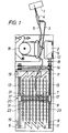
- a sample is sucked out at a sampling point 1.
- the sample can be blood or some other liquid or suspension which is to be analyzed.
- the diluent is pumped by a pump 16 from a container 2 with diluent to the catheter 4 via a tubing 3.
- the same pump 16 is used to pump the mixed sampling liquid 24 via a tubing 5 to a tube 7 which ends over a sample container 23 in a fraction collector in which the sample containers are arranged in parallel rows.
- the fraction collector is designed with the sample containers arranged in parallel rows but fraction collectors can also be used with the sample containers arranged in a spiral shaped pathway or the like.
- the diluent can contain one or several substances which prevent the contents from being coagulated or destroyed in other ways. These substances can also be added to the sample containers in advance in a soluble or solid form.
- the surface in the tubing 5 can also be covered with for example an inhibitor which can either be immobilized or be slowly released into the sampling liquid.
- sample container 23 After the sample container 23 has been filled with sampling liquid the tube is moved to the next sample container and so on. When the last sample container in one row has been filled with sampling liquid the tube is moved to the nearest sample container in the next row in one of several rows of sample containers.
- the sample containers preferably consist of wells in a microtiter plate and the tube 7 is a canula, but other embodiments can also be suitable for specific applications.
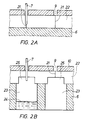
- the containers are covered with an elastic cloth 22 having a slit 21 in which the tube 7 can run.
- Recesses 25 are arranged in the cloth facing the sample containers 23, the diameter of which preferably being a little smaller than the diameter of the sample containers.
- the recesses are preferably centered exactly over the openings of the containers.
- a guiding plate 10 of some stiff material is arranged over the elastic cloth 22 for the purpose of guiding the tube 7 in the slit 21, above all when turned after the last sample container in one row towards the nearest sample container in the next row. Slots 9 are punched in the guiding plate 10 and are located immediately over the corresponing slits in the cloth.
- a device corresponding to the guiding plate is arranged at the end of each row of sample containers.
- the tube 7 When turned between rows of sample containers the tube is forced over to the next row by means of a guiding device.
- a guiding device In a preferred embodiment of the invention, FIG 3, the tube 7 is attached in the middle of a triangular guiding sledge 8 which preferably is arranged to slide along two smooth bars 31 arranged perpendicular to the rows of sample containers.
- the sledge can be arranged to slide in other ways, e.g. in a groove on a bar.
- the bars are in both ends attached to screw pieces 17 which are forced forwards or backwards by means of rotating screw bars 13, a toothed belt 14 and a motor 12 which operates the screw bars 13 via the toothed belt 14.
- the whole part in which the sledge runs is moved forwards when the tube is moved from one sample container to the next sample container.
- the position of the sledge is controlled by a revolution counter 18 as well as an end point and starting point reader 19.
- the reader registers when a portion 20 of the screw piece is immediately opposite the end point or the starting point.
- the reader 19 is used only in the beginning of the sampling, and the remaining control of the position of the tube 7 is handled by a revolution counter 18.
- the revolution counter registers the number of revolutions of the screw bars 13.
- the rotation of the screw bars corresponds to a displacement of the guiding sledge 8 along the row of sample containers.
- the signals from the revolution counter 18 are also used for changing the direction of the motor 12 at the end of each row of sample containers so that the tube 7 follows a zigzag formed pathway along all the sample containers.
- the slot 9 in the underlying guiding plate 10 is then at 33 arranged to follow the pathway of the sledge 8 and thus the tube 7, the pathway coincides with the inclined motion the sledge is forced to make.
- the tube passes a flap 15 in the rigid plate 10, which is located approximatively where the elastic cloth ends. After this point the slot 9 in the guiding plate passes into an open area.
- FIG 4 shows a second embodiment for guiding the tube from one sample container to the next sample container, an alternative guiding device for transferring the tube 7 from one slit in a row of sample containers to the next slit in the next row of sample containers being shown at the same time.
- the tube 7 above the elastic cloth is attached to an endless band 41.
- the band runs around turning wheels 44 arranged at the ends of the rows of sample containers between these.
- the band is preferably easily deflectable laterally but is non-extensible.
- the band is pulled from the first sample container in one corner of the sample plate 6 to the last sample container in the diagonal corner by a motor 43 with driving wheels 42.
- the band 41 pulls the tube 7 around the turning wheel 44.
- the slit in the elastic cloth as well as the slot in the rigid plate runs around the turning wheel 44 to the next row. Since the band 44 provides sufficient steadiness to the tube 7 the rigid guiding plate can be omitted in this embodiment of the invention.
- a flap required for preventing the tube from returning to the same slit since the tube is advanced in the same direction.
- the guiding plate can also be omitted when another type of pathway is chosen.
- the design of the device according to the invention implies a time difference of about 3 minutes from the time of sampling at the sampling point 1 until the sample is delivered into a sample container 23.
- the sampling pump is working as the sample containers are filled, which takes 3 minutes, and the volume from the sampling point 1 to the tube 7 thus corresponds to the volume of one sample container.
- the pump is stopped when the tube 7 is moved between the containers. If sampling has to take place during a considerable preiod of time the system can be designed electronically so that the sampling takes place more slowly. This means that the pump 16 works intermittently.
Landscapes
- Life Sciences & Earth Sciences (AREA)
- Biochemistry (AREA)
- Physics & Mathematics (AREA)
- Health & Medical Sciences (AREA)
- Chemical & Material Sciences (AREA)
- Analytical Chemistry (AREA)
- Hydrology & Water Resources (AREA)
- General Health & Medical Sciences (AREA)
- General Physics & Mathematics (AREA)
- Immunology (AREA)
- Pathology (AREA)
- Sampling And Sample Adjustment (AREA)
- Investigating Or Analysing Biological Materials (AREA)
- Automatic Analysis And Handling Materials Therefor (AREA)
Claims (14)
- Verfahren zum Sammeln von flüssigen Proben, wobei die Probenflüssigkeit (24) mit Hilfe einer Pumpe (16) an einen Probenbehälter (23) über ein Rohr (7) geliefert wird, das durch eine Transportvorrichtung nacheinander von einem Probenbehälter zum nächsten Probenbehälter in mindestens einer Reihe von Probenbehältern bewegt wird, und die Probenflüssigkeit nacheinander zu den Probenbehältern geliefert wird, wobei das Rohr über einem Probenbehälter positioniert ist, dadurch gekennzeichnet, daß ein elastisches Tuch (22) versiegelnd über den Öffnungen des Probenbehälters (23) angebracht wird und sich über die Reihe von Probenbehältern erstreckt, und daß das Rohr (7) dazu gebracht wird, einem Weg in der Form eines Schlitzes (21) zu folgen, der in dem Tuch angeordnet ist, wobei sich der Schlitz über die Öffnungen der Behälter entlang der Reihe von Probenbehältern erstreckt.
- Verfahren nach Anspruch 1, dadurch gekennzeichnet, daß das Rohr (7) zum Stoppen gebracht wird, wenn der Mund des Rohrs sich in einer Ausnehmung (25) in der unteren Fläche des elastischen Tuchs (22) über einem Probenbehälter (23) befindet.
- Verfahren nach Anspruch 1 oder 2, dadurch gekennzeichnet, daß das Rohr (7) an einem Träger (8) befestigt ist, der entlang einer Führung (31) bewegt wird.
- Verfahren nach einem der Ansprüche 1 - 3, dadurch gekennzeichnet, daß das Rohr (7) nach dem letzten Probenbehälter (23) in einer Reihe von dieser Reihe von Probenbehältern zu der nächsten Reihe von Probenbehältern mit Hilfe einer Führungsvorrichtung geführt wird, wenn es mehrere Reihen von Probenbehältern gibt.
- Verfahren nach Anspruch 4, dadurch gekennzeichnet, daß das Rohr (7) beim Übergang von einer Reihe zu der nächsten Reihe von einer Führungsplatte (10) geführt wird, die über dem Schlitz (21) angeordnet ist.
- Verfahren nach einem der Ansprüche 4 - 5, dadurch gekennzeichnet, daß das Rohr (7) beim Übergang von einer Reihe von Probenbehältern zur nächsten Reihe von Probenbehältern von einer Klappe (15) daran gehindert wird, zur vorhergehenden Reihe von Probenbehältern zurückzukehren.
- Verfahren nach Anspruch 1, dadurch gekennzeichnet, daß das Rohr (7) getragen wird und erteilte Bewegung durch ein Endlosband (41), das entlang mehrerer Reihen von Probenbehältern und über sich drehende Räder (44) verläuft, von einer Reihe zur nächsten übergeben wird.
- Vorrichtung zum Sammeln von flüssigen Proben, umfassend eine Pumpe (16) für Probenflüssigkeit (24), ein Rohr (7) für die Bereitstellung der Probenflüssigkeit, Probenbehälter (23) für das Sammeln der Probenflüssigkeit, angeordnet in mindestens einer Reihe, und eine Transportvorrichtung zur Bewegung des Rohrs nacheinander von einem Sammelbehälter zum nächsten Sammelbehälter entlang der Reihe von Sammelbehältern, dadurch gekennzeichnet, daß ein elastisches Tuch (22) versiegelnd über die Öffnungen der Probenbehälter (23) angebracht wird, und daß ein Schlitz (21), in dem das Rohr (7) beweglich ist, im Tuch angeordnet ist, das sich entlang der Reihe der Probenbehälter erstreckt.
- Vorrichtung nach Anspruch 8, dadurch gekennzeichnet, daß das Rohr (7) an einem Träger (8) befestigt ist, der beweglich auf einer Führung (31) geführt wird, die entlang des Schlitzes angeordnet ist.
- Vorrichtung nach einem der Ansprüche 8 - 9, dadurch gekennzeichnet, daß mehrere Probenbehälter angeordnet sind, und daß eine Fuhrungsvorrichtung nach dem letzten Probenbehälter (23) in einer Reihe für die Führung des Rohrs (7) von dieser Reihe von Probenbehältern zur nächsten Reihe von Probenbehältern angeordnet ist.
- Vorrichtung nach Anspruch 10, dadurch gekennzeichnet, daß das Rohr (7) an einem Endlosband (41) befestigt ist und von diesem getragen wird, das entlang mehrerer Reihen von Probenbehältern weiterbewegt wird und über sich drehende Räder (44) von einer Reihe von Probenbehältern (23) zur nächsten Reihe von Probenbehältern geführt wird.
- Vorrichtung nach einem der Ansprüche 8 - 11, dadurch gekennzeichnet, daß eine Führungsplatte (10) über dem Schlitz (21) angeordnet ist, in dem ein Schlitz (9) angeordnet ist, um das Rohr (7) dazu zu bringen, dem Weg des Schlitzes zu folgen.
- Vorrichtung nach Anspruch 9 oder 10, dadurch gekennzeichnet, daß die Führung (31) senkrecht zu den Reihen von Probenbehältern (23) ist, und daß die Führung an ihren Enden an Mittel (17) zum Transport der Führung entlang der Reihen von Probenbehältern angebracht ist,
- Vorrichtung nach Anspruch 8, dadurch gekennzeichnet, daß eine Ausnehmung (25) über jedem Probenbehälter (23) in der unteren Fläche des elastischen Tuchs (22) angeordnet ist.
Applications Claiming Priority (3)
| Application Number | Priority Date | Filing Date | Title |
|---|---|---|---|
| SE9304193 | 1993-12-17 | ||
| SE9304193A SE502568C2 (sv) | 1993-12-17 | 1993-12-17 | Sätt och anordning vid uppsamling av vätskeprov |
| PCT/SE1994/001063 WO1995016632A1 (en) | 1993-12-17 | 1994-11-14 | Method and device for collection of liquid samples |
Publications (2)
| Publication Number | Publication Date |
|---|---|
| EP0734351A1 EP0734351A1 (de) | 1996-10-02 |
| EP0734351B1 true EP0734351B1 (de) | 1997-09-17 |
Family
ID=20392129
Family Applications (1)
| Application Number | Title | Priority Date | Filing Date |
|---|---|---|---|
| EP95919263A Expired - Lifetime EP0734351B1 (de) | 1993-12-17 | 1994-11-14 | Verfahren und vorrichtung zum sammeln flüssiger proben |
Country Status (8)
| Country | Link |
|---|---|
| US (1) | US5942441A (de) |
| EP (1) | EP0734351B1 (de) |
| JP (1) | JPH09506708A (de) |
| AT (1) | ATE158262T1 (de) |
| AU (1) | AU1285695A (de) |
| DE (1) | DE69405779T2 (de) |
| SE (1) | SE502568C2 (de) |
| WO (1) | WO1995016632A1 (de) |
Families Citing this family (6)
| Publication number | Priority date | Publication date | Assignee | Title |
|---|---|---|---|---|
| US6071748A (en) * | 1997-07-16 | 2000-06-06 | Ljl Biosystems, Inc. | Light detection device |
| AU2000229082A1 (en) * | 2000-02-08 | 2001-08-20 | Cybio Instruments Gmbh | Method and device fo collecting fractions after material separation |
| FR2835616B1 (fr) * | 2002-02-01 | 2005-02-11 | Junior Instruments | Dispositif pour l'analyse automatisee d'un echantillon liquide |
| US7396512B2 (en) | 2003-11-04 | 2008-07-08 | Drummond Scientific Company | Automatic precision non-contact open-loop fluid dispensing |
| WO2006132620A1 (en) * | 2005-06-03 | 2006-12-14 | Alfa Wassermann, Inc. | Fraction collector |
| KR100758818B1 (ko) | 2006-06-29 | 2007-09-19 | 김학성 | 자동 채수기 |
Family Cites Families (5)
| Publication number | Priority date | Publication date | Assignee | Title |
|---|---|---|---|---|
| US3450173A (en) * | 1966-12-22 | 1969-06-17 | Univ Yeshiva | Fraction collector |
| US3623515A (en) * | 1969-09-26 | 1971-11-30 | Warren E Gilson | Fraction collector |
| SE381826B (sv) * | 1974-01-16 | 1975-12-22 | Duni Bila Ab | Forfarande vid kemiska arbetsoperationer samt produkt for utforande av forfarandet |
| US4362698A (en) * | 1980-03-07 | 1982-12-07 | Sherman-Boosalis Corporation | Closures for fluid sample cups |
| WO1987007911A1 (en) * | 1986-06-20 | 1987-12-30 | The University Of Manchester Institute Of Science | Sampling of material |
-
1993
- 1993-12-17 SE SE9304193A patent/SE502568C2/sv unknown
-
1994
- 1994-11-14 AT AT95919263T patent/ATE158262T1/de not_active IP Right Cessation
- 1994-11-14 WO PCT/SE1994/001063 patent/WO1995016632A1/en not_active Ceased
- 1994-11-14 EP EP95919263A patent/EP0734351B1/de not_active Expired - Lifetime
- 1994-11-14 DE DE69405779T patent/DE69405779T2/de not_active Expired - Fee Related
- 1994-11-14 US US08/666,404 patent/US5942441A/en not_active Expired - Fee Related
- 1994-11-14 AU AU12856/95A patent/AU1285695A/en not_active Abandoned
- 1994-11-14 JP JP7516694A patent/JPH09506708A/ja active Pending
Also Published As
| Publication number | Publication date |
|---|---|
| ATE158262T1 (de) | 1997-10-15 |
| SE9304193L (sv) | 1995-06-18 |
| SE9304193D0 (sv) | 1993-12-17 |
| JPH09506708A (ja) | 1997-06-30 |
| DE69405779D1 (de) | 1997-10-23 |
| WO1995016632A1 (en) | 1995-06-22 |
| AU1285695A (en) | 1995-07-03 |
| US5942441A (en) | 1999-08-24 |
| EP0734351A1 (de) | 1996-10-02 |
| SE502568C2 (sv) | 1995-11-13 |
| DE69405779T2 (de) | 1998-02-05 |
Similar Documents
| Publication | Publication Date | Title |
|---|---|---|
| US5134079A (en) | Fluid sample collection and delivery system and methods particularly adapted for body fluid sampling | |
| US5380665A (en) | Fluid sample collection and delivery system and methods particularly adapted for body fluid sampling | |
| DE3884280T2 (de) | Probenröhrchentransportsystem für ein Analysegerät. | |
| US3809871A (en) | Programmable physiological infusion | |
| US6017318A (en) | Feedback controlled drug delivery system | |
| DE69233170T2 (de) | Reagenzbehälter mit Deckel | |
| US4976590A (en) | Fluid conduit-responsively adjustable pump arrangement and pump/conduit arrangement and method, and fluid conduits therefor | |
| DE69927449T2 (de) | Automatisches Messgerät mit ringförmiger Förderanlage | |
| EP0734351B1 (de) | Verfahren und vorrichtung zum sammeln flüssiger proben | |
| DE2829215A1 (de) | Medizinische infusionsvorrichtung mit pumpe | |
| NL8702591A (nl) | Geautomatiseerde inrichting voor het analyseren van steekproeven bij patienten. | |
| DE2140555C3 (de) | Automatischer Analysator | |
| DE3877453T2 (de) | Analysator mit vom inkubator separierter waschstation. | |
| WO2022038616A1 (en) | Devices and systems for automated collection of blood into tube stored at atmospheric pressure | |
| CA1318823C (en) | Precision liquid handling apparatus | |
| US3841160A (en) | Automatic sampler apparatus | |
| EP1092140B1 (de) | Verfahren und vorrichtung zur entnahme von flüssigen proben aus einem verschlossenen gefäss | |
| DE69306671T2 (de) | Vorrichtung und verfahren zur bestimmung von gerinnung | |
| GB2112519A (en) | Hydrodynamic sample introduction system | |
| EP0588236A2 (de) | Flüssigkeitsabgabevorrichtung | |
| EP0504313A1 (de) | Probenhantiersystem für optisches überwachungssystem. | |
| Burtis et al. | Automated sample-reagent loader for use with the GeMSAEC fast analyzer | |
| US4998866A (en) | Precision liquid handling apparatus | |
| DE2627237C3 (de) | ||
| Christian | Novel flow injection analysis systems for drug analysis |
Legal Events
| Date | Code | Title | Description |
|---|---|---|---|
| PUAI | Public reference made under article 153(3) epc to a published international application that has entered the european phase |
Free format text: ORIGINAL CODE: 0009012 |
|
| 17P | Request for examination filed |
Effective date: 19960531 |
|
| AK | Designated contracting states |
Kind code of ref document: A1 Designated state(s): AT BE CH DE DK ES FR GB IT LI NL |
|
| GRAG | Despatch of communication of intention to grant |
Free format text: ORIGINAL CODE: EPIDOS AGRA |
|
| 17Q | First examination report despatched |
Effective date: 19961129 |
|
| GRAH | Despatch of communication of intention to grant a patent |
Free format text: ORIGINAL CODE: EPIDOS IGRA |
|
| GRAH | Despatch of communication of intention to grant a patent |
Free format text: ORIGINAL CODE: EPIDOS IGRA |
|
| GRAA | (expected) grant |
Free format text: ORIGINAL CODE: 0009210 |
|
| AK | Designated contracting states |
Kind code of ref document: B1 Designated state(s): AT BE CH DE DK ES FR GB IT LI NL |
|
| PG25 | Lapsed in a contracting state [announced via postgrant information from national office to epo] |
Ref country code: NL Free format text: LAPSE BECAUSE OF FAILURE TO SUBMIT A TRANSLATION OF THE DESCRIPTION OR TO PAY THE FEE WITHIN THE PRESCRIBED TIME-LIMIT Effective date: 19970917 Ref country code: LI Free format text: LAPSE BECAUSE OF FAILURE TO SUBMIT A TRANSLATION OF THE DESCRIPTION OR TO PAY THE FEE WITHIN THE PRESCRIBED TIME-LIMIT Effective date: 19970917 Ref country code: IT Free format text: LAPSE BECAUSE OF FAILURE TO SUBMIT A TRANSLATION OF THE DESCRIPTION OR TO PAY THE FEE WITHIN THE PRE;WARNING: LAPSES OF ITALIAN PATENTS WITH EFFECTIVE DATE BEFORE 2007 MAY HAVE OCCURRED AT ANY TIME BEFORE 2007. THE CORRECT EFFECTIVE DATE MAY BE DIFFERENT FROM THE ONE RECORDED.SCRIBED TIME-LIMIT Effective date: 19970917 Ref country code: ES Free format text: THE PATENT HAS BEEN ANNULLED BY A DECISION OF A NATIONAL AUTHORITY Effective date: 19970917 Ref country code: DK Free format text: LAPSE BECAUSE OF NON-PAYMENT OF DUE FEES Effective date: 19970917 Ref country code: CH Free format text: LAPSE BECAUSE OF FAILURE TO SUBMIT A TRANSLATION OF THE DESCRIPTION OR TO PAY THE FEE WITHIN THE PRESCRIBED TIME-LIMIT Effective date: 19970917 Ref country code: BE Effective date: 19970917 Ref country code: AT Effective date: 19970917 |
|
| REF | Corresponds to: |
Ref document number: 158262 Country of ref document: AT Date of ref document: 19971015 Kind code of ref document: T |
|
| REG | Reference to a national code |
Ref country code: CH Ref legal event code: EP |
|
| REF | Corresponds to: |
Ref document number: 69405779 Country of ref document: DE Date of ref document: 19971023 |
|
| ET | Fr: translation filed | ||
| PGFP | Annual fee paid to national office [announced via postgrant information from national office to epo] |
Ref country code: DE Payment date: 19971114 Year of fee payment: 4 |
|
| PGFP | Annual fee paid to national office [announced via postgrant information from national office to epo] |
Ref country code: FR Payment date: 19971128 Year of fee payment: 4 |
|
| NLV1 | Nl: lapsed or annulled due to failure to fulfill the requirements of art. 29p and 29m of the patents act | ||
| REG | Reference to a national code |
Ref country code: CH Ref legal event code: PL |
|
| PLBE | No opposition filed within time limit |
Free format text: ORIGINAL CODE: 0009261 |
|
| STAA | Information on the status of an ep patent application or granted ep patent |
Free format text: STATUS: NO OPPOSITION FILED WITHIN TIME LIMIT |
|
| 26N | No opposition filed | ||
| PG25 | Lapsed in a contracting state [announced via postgrant information from national office to epo] |
Ref country code: GB Free format text: LAPSE BECAUSE OF NON-PAYMENT OF DUE FEES Effective date: 19981114 |
|
| GBPC | Gb: european patent ceased through non-payment of renewal fee |
Effective date: 19981114 |
|
| PG25 | Lapsed in a contracting state [announced via postgrant information from national office to epo] |
Ref country code: FR Free format text: LAPSE BECAUSE OF NON-PAYMENT OF DUE FEES Effective date: 19990730 |
|
| REG | Reference to a national code |
Ref country code: FR Ref legal event code: ST |
|
| PG25 | Lapsed in a contracting state [announced via postgrant information from national office to epo] |
Ref country code: DE Free format text: LAPSE BECAUSE OF NON-PAYMENT OF DUE FEES Effective date: 19990901 |