EP0734351B1 - Method and device for collection of liquid samples - Google Patents
Method and device for collection of liquid samples Download PDFInfo
- Publication number
- EP0734351B1 EP0734351B1 EP95919263A EP95919263A EP0734351B1 EP 0734351 B1 EP0734351 B1 EP 0734351B1 EP 95919263 A EP95919263 A EP 95919263A EP 95919263 A EP95919263 A EP 95919263A EP 0734351 B1 EP0734351 B1 EP 0734351B1
- Authority
- EP
- European Patent Office
- Prior art keywords
- tube
- row
- sample containers
- sample
- over
- Prior art date
- Legal status (The legal status is an assumption and is not a legal conclusion. Google has not performed a legal analysis and makes no representation as to the accuracy of the status listed.)
- Expired - Lifetime
Links
Images

Classifications
-
- G—PHYSICS
- G01—MEASURING; TESTING
- G01N—INVESTIGATING OR ANALYSING MATERIALS BY DETERMINING THEIR CHEMICAL OR PHYSICAL PROPERTIES
- G01N1/00—Sampling; Preparing specimens for investigation
- G01N1/02—Devices for withdrawing samples
- G01N1/10—Devices for withdrawing samples in the liquid or fluent state
- G01N1/18—Devices for withdrawing samples in the liquid or fluent state with provision for splitting samples into portions
- G01N2001/185—Conveyor of containers successively filled
-
- G—PHYSICS
- G01—MEASURING; TESTING
- G01N—INVESTIGATING OR ANALYSING MATERIALS BY DETERMINING THEIR CHEMICAL OR PHYSICAL PROPERTIES
- G01N33/00—Investigating or analysing materials by specific methods not covered by groups G01N1/00 - G01N31/00
- G01N33/48—Biological material, e.g. blood, urine; Haemocytometers
- G01N33/483—Physical analysis of biological material
- G01N33/487—Physical analysis of biological material of liquid biological material
- G01N33/49—Blood
-
- Y—GENERAL TAGGING OF NEW TECHNOLOGICAL DEVELOPMENTS; GENERAL TAGGING OF CROSS-SECTIONAL TECHNOLOGIES SPANNING OVER SEVERAL SECTIONS OF THE IPC; TECHNICAL SUBJECTS COVERED BY FORMER USPC CROSS-REFERENCE ART COLLECTIONS [XRACs] AND DIGESTS
- Y10—TECHNICAL SUBJECTS COVERED BY FORMER USPC
- Y10T—TECHNICAL SUBJECTS COVERED BY FORMER US CLASSIFICATION
- Y10T436/00—Chemistry: analytical and immunological testing
- Y10T436/11—Automated chemical analysis
- Y10T436/119163—Automated chemical analysis with aspirator of claimed structure
-
- Y—GENERAL TAGGING OF NEW TECHNOLOGICAL DEVELOPMENTS; GENERAL TAGGING OF CROSS-SECTIONAL TECHNOLOGIES SPANNING OVER SEVERAL SECTIONS OF THE IPC; TECHNICAL SUBJECTS COVERED BY FORMER USPC CROSS-REFERENCE ART COLLECTIONS [XRACs] AND DIGESTS
- Y10—TECHNICAL SUBJECTS COVERED BY FORMER USPC
- Y10T—TECHNICAL SUBJECTS COVERED BY FORMER US CLASSIFICATION
- Y10T436/00—Chemistry: analytical and immunological testing
- Y10T436/25—Chemistry: analytical and immunological testing including sample preparation
- Y10T436/25625—Dilution
-
- Y—GENERAL TAGGING OF NEW TECHNOLOGICAL DEVELOPMENTS; GENERAL TAGGING OF CROSS-SECTIONAL TECHNOLOGIES SPANNING OVER SEVERAL SECTIONS OF THE IPC; TECHNICAL SUBJECTS COVERED BY FORMER USPC CROSS-REFERENCE ART COLLECTIONS [XRACs] AND DIGESTS
- Y10—TECHNICAL SUBJECTS COVERED BY FORMER USPC
- Y10T—TECHNICAL SUBJECTS COVERED BY FORMER US CLASSIFICATION
- Y10T436/00—Chemistry: analytical and immunological testing
- Y10T436/25—Chemistry: analytical and immunological testing including sample preparation
- Y10T436/2575—Volumetric liquid transfer
Definitions
- the invention refers to a method for collection of liquid samples as well as a device for carrying out the method according to the invention. More specificially, the invention refers to a method in which a sampling liquid is delivered by means of a pump to a sample container via a tube which is moved by a transport device in succession from one sample container to the next sample container in several rows of sample containers, the tube after the last sample container in a row being moved to the nearest sample container in the next row.
- results from the analysis are utilized directly, e.g. for regulating the dosage of insulin.
- results from the analysis are not to be used until a test series is completed the same information can be obtained if the laboratory analyses all the samples afterwards.
- separate samples are collected at a certain sampling several different types of analyses can advantageously be performed on the same sample.
- the apparatus In order to further facilitate a flexible use the apparatus should be designed to be portable. However, a simple portable system for continuous blood sampling or other kinds of sampling does not exist on the market. An essential prerequisite for a portable equipment is that the liquid samples are not spilled. Furthermore, it is desirable if the samples, when necessary, can be handled aseptically.
- the purpose of the present invention is to facilitate and simplify the method of regular or continuous sampling above all during blood sampling by using a portable device which gives a low manufacturing cost.
- the device for collection of liquid samples according to the invention includes a special fraction collector which is so constructed that the samples are not spoiled even if the device is turned sideways or upside down.
- a sample is sucked out at a sampling point 1.
- the sample can be blood or some other liquid or suspension which is to be analyzed.
- the diluent is pumped by a pump 16 from a container 2 with diluent to the catheter 4 via a tubing 3.
- the same pump 16 is used to pump the mixed sampling liquid 24 via a tubing 5 to a tube 7 which ends over a sample container 23 in a fraction collector in which the sample containers are arranged in parallel rows.
- the fraction collector is designed with the sample containers arranged in parallel rows but fraction collectors can also be used with the sample containers arranged in a spiral shaped pathway or the like.
- the diluent can contain one or several substances which prevent the contents from being coagulated or destroyed in other ways. These substances can also be added to the sample containers in advance in a soluble or solid form.
- the surface in the tubing 5 can also be covered with for example an inhibitor which can either be immobilized or be slowly released into the sampling liquid.
- sample container 23 After the sample container 23 has been filled with sampling liquid the tube is moved to the next sample container and so on. When the last sample container in one row has been filled with sampling liquid the tube is moved to the nearest sample container in the next row in one of several rows of sample containers.
- the sample containers preferably consist of wells in a microtiter plate and the tube 7 is a canula, but other embodiments can also be suitable for specific applications.
- the containers are covered with an elastic cloth 22 having a slit 21 in which the tube 7 can run.
- Recesses 25 are arranged in the cloth facing the sample containers 23, the diameter of which preferably being a little smaller than the diameter of the sample containers.
- the recesses are preferably centered exactly over the openings of the containers.
- a guiding plate 10 of some stiff material is arranged over the elastic cloth 22 for the purpose of guiding the tube 7 in the slit 21, above all when turned after the last sample container in one row towards the nearest sample container in the next row. Slots 9 are punched in the guiding plate 10 and are located immediately over the corresponing slits in the cloth.
- a device corresponding to the guiding plate is arranged at the end of each row of sample containers.
- the tube 7 When turned between rows of sample containers the tube is forced over to the next row by means of a guiding device.
- a guiding device In a preferred embodiment of the invention, FIG 3, the tube 7 is attached in the middle of a triangular guiding sledge 8 which preferably is arranged to slide along two smooth bars 31 arranged perpendicular to the rows of sample containers.
- the sledge can be arranged to slide in other ways, e.g. in a groove on a bar.
- the bars are in both ends attached to screw pieces 17 which are forced forwards or backwards by means of rotating screw bars 13, a toothed belt 14 and a motor 12 which operates the screw bars 13 via the toothed belt 14.
- the whole part in which the sledge runs is moved forwards when the tube is moved from one sample container to the next sample container.
- the position of the sledge is controlled by a revolution counter 18 as well as an end point and starting point reader 19.
- the reader registers when a portion 20 of the screw piece is immediately opposite the end point or the starting point.
- the reader 19 is used only in the beginning of the sampling, and the remaining control of the position of the tube 7 is handled by a revolution counter 18.
- the revolution counter registers the number of revolutions of the screw bars 13.
- the rotation of the screw bars corresponds to a displacement of the guiding sledge 8 along the row of sample containers.
- the signals from the revolution counter 18 are also used for changing the direction of the motor 12 at the end of each row of sample containers so that the tube 7 follows a zigzag formed pathway along all the sample containers.
- the slot 9 in the underlying guiding plate 10 is then at 33 arranged to follow the pathway of the sledge 8 and thus the tube 7, the pathway coincides with the inclined motion the sledge is forced to make.
- the tube passes a flap 15 in the rigid plate 10, which is located approximatively where the elastic cloth ends. After this point the slot 9 in the guiding plate passes into an open area.
- FIG 4 shows a second embodiment for guiding the tube from one sample container to the next sample container, an alternative guiding device for transferring the tube 7 from one slit in a row of sample containers to the next slit in the next row of sample containers being shown at the same time.
- the tube 7 above the elastic cloth is attached to an endless band 41.
- the band runs around turning wheels 44 arranged at the ends of the rows of sample containers between these.
- the band is preferably easily deflectable laterally but is non-extensible.
- the band is pulled from the first sample container in one corner of the sample plate 6 to the last sample container in the diagonal corner by a motor 43 with driving wheels 42.
- the band 41 pulls the tube 7 around the turning wheel 44.
- the slit in the elastic cloth as well as the slot in the rigid plate runs around the turning wheel 44 to the next row. Since the band 44 provides sufficient steadiness to the tube 7 the rigid guiding plate can be omitted in this embodiment of the invention.
- a flap required for preventing the tube from returning to the same slit since the tube is advanced in the same direction.
- the guiding plate can also be omitted when another type of pathway is chosen.
- the design of the device according to the invention implies a time difference of about 3 minutes from the time of sampling at the sampling point 1 until the sample is delivered into a sample container 23.
- the sampling pump is working as the sample containers are filled, which takes 3 minutes, and the volume from the sampling point 1 to the tube 7 thus corresponds to the volume of one sample container.
- the pump is stopped when the tube 7 is moved between the containers. If sampling has to take place during a considerable preiod of time the system can be designed electronically so that the sampling takes place more slowly. This means that the pump 16 works intermittently.
Abstract
Description
- The invention refers to a method for collection of liquid samples as well as a device for carrying out the method according to the invention. More specificially, the invention refers to a method in which a sampling liquid is delivered by means of a pump to a sample container via a tube which is moved by a transport device in succession from one sample container to the next sample container in several rows of sample containers, the tube after the last sample container in a row being moved to the nearest sample container in the next row.
- When medicinal samples are taken - as well as in other instances - a person has to go to the patient or to a place for sampling in order to obtain the necessary sample by means of a canula or some other sampling instrument. This procedure has to be repeated each time a sample is taken. If kinetic changes are to be followed the sampling has to take place with some regularity so that concentration changes with time can be determined with any relevance in subsequent analyses.
- The most usual way to regularly take medicinal samples is that somebody inserts a canula into the patient and collects a sample of intervals of for with half an hour. The samples are then transported to another place for analysis, e.g. a laboratory. However, when the results from the analysis are not of acute significance the analysis of the samples can wait until all the samples have been taken.
- Apparatuses for regular sampling of blood are described. These apparatuses, built around conventional fraction collectors, are big and can not easily be carried. The patient must thus remain in the vicinity of the permanently stationed apparatus. Systems are also described in which the analysis of the sample takes place continuously. In these cases the analysis is usually based on the determination of glucose. Such a system is described in US-A-4 123 353.
- In more expensive systems for blood sampling the results from the analysis are utilized directly, e.g. for regulating the dosage of insulin. On the other hand, if the results from the analysis are not to be used until a test series is completed the same information can be obtained if the laboratory analyses all the samples afterwards. Furthermore, if separate samples are collected at a certain sampling several different types of analyses can advantageously be performed on the same sample.
- In order to further facilitate a flexible use the apparatus should be designed to be portable. However, a simple portable system for continuous blood sampling or other kinds of sampling does not exist on the market. An essential prerequisite for a portable equipment is that the liquid samples are not spilled. Furthermore, it is desirable if the samples, when necessary, can be handled aseptically.
- The purpose of the present invention is to facilitate and simplify the method of regular or continuous sampling above all during blood sampling by using a portable device which gives a low manufacturing cost. The device for collection of liquid samples according to the invention includes a special fraction collector which is so constructed that the samples are not spoiled even if the device is turned sideways or upside down.
- In order to achieve this purpose the invention has obtained the characterizing features of
claim - In order to explain the invention in more detail two embodiments thereof will be described below reference being made to the accompanying drawings in which
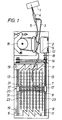
- FIG 1 is an overall view of a device according to the invention,
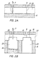
- FIG 2A is a detail view of the device in cross section,
- FIG 2B corresponds to FIG 2A but shows another cross section which illustrates another point of the course of sampling,
- FIG 3 is a detail view of the device according to FIG 1, and
- FIG 4 shows another embodiment of a device according to the invention.
- In the overall view of FIG 1 a sample is sucked out at a
sampling point 1. The sample can be blood or some other liquid or suspension which is to be analyzed. At the same time as the sample is sucked out it is usually diluted and mixed with a diluent. This preferably takes place in the tip of a double-lumen catheter 4. The diluent is pumped by a pump 16 from acontainer 2 with diluent to the catheter 4 via atubing 3. The same pump 16 is used to pump the mixedsampling liquid 24 via atubing 5 to atube 7 which ends over asample container 23 in a fraction collector in which the sample containers are arranged in parallel rows. In a preferred embodiment of the invention the fraction collector is designed with the sample containers arranged in parallel rows but fraction collectors can also be used with the sample containers arranged in a spiral shaped pathway or the like. - The diluent can contain one or several substances which prevent the contents from being coagulated or destroyed in other ways. These substances can also be added to the sample containers in advance in a soluble or solid form. The surface in the
tubing 5 can also be covered with for example an inhibitor which can either be immobilized or be slowly released into the sampling liquid. - After the
sample container 23 has been filled with sampling liquid the tube is moved to the next sample container and so on. When the last sample container in one row has been filled with sampling liquid the tube is moved to the nearest sample container in the next row in one of several rows of sample containers. The sample containers preferably consist of wells in a microtiter plate and thetube 7 is a canula, but other embodiments can also be suitable for specific applications. - In order to prevent the samples from leaking out from the filled sample containers these can be covered by a septum which is penetrated by the canula in every container. This procedure is preferred if it is required that the samples must be handled sterilely. However, as shown in FIG 2A, the containers are covered with an
elastic cloth 22 having aslit 21 in which thetube 7 can run.Recesses 25 are arranged in the cloth facing thesample containers 23, the diameter of which preferably being a little smaller than the diameter of the sample containers. The recesses are preferably centered exactly over the openings of the containers. When the tube in thecloth 22 is brought to follow theslit 21 between twosample containers 23 the tube does not completely penetrate the cloth. However, in therecesses 25 over each sample container, FIG 2B, the tube reaches so far down within the slit that the tip of the tube runs free from the elastic cloth. By this design of the elastic cloth it is avoided that sampling liquid penetrates into the slit when the liquid leaves the tube and that liquid is transferred between the sample containers. If a sterile procedure is not absolutely necessary this handling of the sample is sufficient. - In this embodiment, a guiding
plate 10 of some stiff material is arranged over theelastic cloth 22 for the purpose of guiding thetube 7 in theslit 21, above all when turned after the last sample container in one row towards the nearest sample container in the next row.Slots 9 are punched in the guidingplate 10 and are located immediately over the corresponing slits in the cloth. In other applications a device corresponding to the guiding plate is arranged at the end of each row of sample containers. - When turned between rows of sample containers the tube is forced over to the next row by means of a guiding device. In a preferred embodiment of the invention, FIG 3, the
tube 7 is attached in the middle of a triangular guidingsledge 8 which preferably is arranged to slide along twosmooth bars 31 arranged perpendicular to the rows of sample containers. The sledge can be arranged to slide in other ways, e.g. in a groove on a bar. - The bars are in both ends attached to
screw pieces 17 which are forced forwards or backwards by means of rotatingscrew bars 13, atoothed belt 14 and amotor 12 which operates thescrew bars 13 via thetoothed belt 14. The whole part in which the sledge runs is moved forwards when the tube is moved from one sample container to the next sample container. The position of the sledge is controlled by arevolution counter 18 as well as an end point andstarting point reader 19. The reader registers when a portion 20 of the screw piece is immediately opposite the end point or the starting point. In a preferred embodiment of the invention thereader 19 is used only in the beginning of the sampling, and the remaining control of the position of thetube 7 is handled by arevolution counter 18. The revolution counter registers the number of revolutions of thescrew bars 13. The rotation of the screw bars corresponds to a displacement of the guidingsledge 8 along the row of sample containers. By measuring the rotation of the screw bars it is possible to determine the position of thetube 7 so that it can be guided to be moved between two sample containers in a row. The signals from therevolution counter 18 are also used for changing the direction of themotor 12 at the end of each row of sample containers so that thetube 7 follows a zigzag formed pathway along all the sample containers. - When a row of sample containers, usually 12, have been filled the sledge together with its tube is forced over to the next row of sample containers either by means of the
slots 9 in the guiding plate or by means of aninclined deflection bar 11 which facilitates the passage of thetube 7 to the next row of sample containers. The passage takes place in such a way that the sledge continues in the same direction after the last sample container in one row has been filled with sampling liquid. Then at 33 the downward projectingtube 7, and thus thesledge 8, are forced aside by the deflectingslot 9 in the guidingplate 10. However, aninclined deflection bar 11 preferably assists in the passage by forcing aside thetriangular sledge 8 in this case. Theslot 9 in the underlying guidingplate 10 is then at 33 arranged to follow the pathway of thesledge 8 and thus thetube 7, the pathway coincides with the inclined motion the sledge is forced to make. At the same time the tube passes aflap 15 in therigid plate 10, which is located approximatively where the elastic cloth ends. After this point theslot 9 in the guiding plate passes into an open area. - When the
motor 12 operating the part including the sledge changes rotational direction the tube will be forced into thenext slot 9 in the guidingplate 10 by the inclined design of the plate above theflap 15. Then the tube is forced into the correspondingslot 21 in thecloth 22. The flap mentioned above thus prevents the tube from returning to the slot from which it came. - FIG 4 shows a second embodiment for guiding the tube from one sample container to the next sample container, an alternative guiding device for transferring the
tube 7 from one slit in a row of sample containers to the next slit in the next row of sample containers being shown at the same time. In this case thetube 7 above the elastic cloth is attached to anendless band 41. The band runs around turningwheels 44 arranged at the ends of the rows of sample containers between these. In order to ensure a proper position for the tube when it discharges liquid to the sample containers the band is preferably easily deflectable laterally but is non-extensible. The band is pulled from the first sample container in one corner of thesample plate 6 to the last sample container in the diagonal corner by a motor 43 with drivingwheels 42. At the passage between two rows of sample containers theband 41 pulls thetube 7 around theturning wheel 44. In this case the slit in the elastic cloth as well as the slot in the rigid plate runs around theturning wheel 44 to the next row. Since theband 44 provides sufficient steadiness to thetube 7 the rigid guiding plate can be omitted in this embodiment of the invention. Nor is a flap required for preventing the tube from returning to the same slit since the tube is advanced in the same direction. The guiding plate can also be omitted when another type of pathway is chosen. - In practice, at continuous operation the design of the device according to the invention implies a time difference of about 3 minutes from the time of sampling at the
sampling point 1 until the sample is delivered into asample container 23. The sampling pump is working as the sample containers are filled, which takes 3 minutes, and the volume from thesampling point 1 to thetube 7 thus corresponds to the volume of one sample container. The pump is stopped when thetube 7 is moved between the containers. If sampling has to take place during a considerable preiod of time the system can be designed electronically so that the sampling takes place more slowly. This means that the pump 16 works intermittently. If, for example, a sample for one container is to be sampled during 10 minutes in stead of 3 minutes the pump works for 6 seconds and is idle for 14 seconds, and this sequence is repeated those 30 times which are required for filling one container. The same procedure is repeated for the remaining containers. The advantage of this procedure is that blood corpuscles etc. do not remain stationary in the tubings for a long continuous period of time and at the same time the length of tubing from thesampling point 1 to thetube 7 will not become critical.
Claims (14)
- Method for collection of liquid samples, wherein the sampling liquid (24) is delivered by means of a pump (16) to a sample container (23) via a tube (7) which is moved by a transport device in succession from one sample container to the next sample container in at least one row of sample containers, and the sampling liquid is delivered to the sample containers one at a time with the tube positioned over a sample container characterized in that an elastic cloth (22) is sealingly applied over the openings of the sample containers (23) and extending over the row of sample containers, and that the tube (7) is brought to follow a pathway in the form of a slit (21) arranged in the cloth, the slit extending over the openings of the containers along the row of sample containers.
- Method as claimed in claim 1, characterized in that the tube (7) is brought to stop when the mouth of the tube is in a recess (25) in the lower surface of the elastic cloth (22) over a sample container (23).
- Method as claimed in claim 1 or 2, characterized in that the tube (7) is mounted to a carrier (8) which is moved along a guide (31).
- Method as claimed in any of claims 1-3, characterized in that the tube (7) after the last sample container (23) in a row is guided from this row of sample containers over to the next row of sample containers by means of a guiding device when there are several rows of sample containers.
- Method as claimed in claim 4, characterized in that the tube (7) when passing from one row to the next row is guided by a guiding plate (10) arranged over the slit (21).
- Method as claimed in any of claims 4-5, characterized in that the tube (7) when passing from one a row of sample containers to the next row of sample containers is prevented by a flap (15) from returning to the previous row of sample containers.
- Method as claimed in claims 1, characterized in that the tube (7) is carried and imparted movement by an endless band (41) which runs along several rows of sample containers and over turning wheels (44) is passed from one row to the next.
- Device for collection of liquid samples comprising a pump (16) for sampling liquid (24), a tube (7) for delivering the sampling liquid, sample containers (23) for collection of the sampling liquid arranged in at least one row, and a transport device for moving the tube in succession from one sample container to the next sample container along the row of sample containers, characterized in that an elastic cloth (22) is sealingly applied over the openings of the sample containers (23), and that a slit (21) in which the tube (7) is movable is arranged in the cloth, extending along the row of sample containers.
- Device as claimed in claim 8, characterized in that the tube (7) is mounted to a carrier (8) which is movably guided on a guide (31) arranged along the slit.
- Device as claimed in any of claims 8-9, characterized in that several rows of sample containers are arranged, and that a guiding device is arranged after the last sample container (23) in a row for guiding the tube (7) from this row of sample containers over to the next row of sample containers.
- Device as claimed in claim 10, characterized in that the tube (7) is attached to and carried by an endless band (41) which is advanced along several rows of sample containers and is guided over turning wheels (44) from one row of sample containers (23) to the next row of sample containers.
- Device as claimed in any of claims 8-11, characterized in that a guiding plate (10) is arranged over the slit (21), in which a slot (9) is arranged in order to force the tube (7) to follow the pathway of the slit.
- Device as claimed in claim 9 or 10, characterized in that the guide (31) is perpendicular to the rows of sample containers (23), and that the guide in its ends is attached to means (17) for transportation of the guide along the rows of sample containers.
- Device as claimed in claim 8, characterized in that a recess (25) is arranged over each sample container (23) in the lower surface of the elastic cloth (22).
Applications Claiming Priority (3)
| Application Number | Priority Date | Filing Date | Title |
|---|---|---|---|
| SE9304193A SE502568C2 (en) | 1993-12-17 | 1993-12-17 | Method and apparatus for collecting fluid samples |
| SE9304193 | 1993-12-17 | ||
| PCT/SE1994/001063 WO1995016632A1 (en) | 1993-12-17 | 1994-11-14 | Method and device for collection of liquid samples |
Publications (2)
| Publication Number | Publication Date |
|---|---|
| EP0734351A1 EP0734351A1 (en) | 1996-10-02 |
| EP0734351B1 true EP0734351B1 (en) | 1997-09-17 |
Family
ID=20392129
Family Applications (1)
| Application Number | Title | Priority Date | Filing Date |
|---|---|---|---|
| EP95919263A Expired - Lifetime EP0734351B1 (en) | 1993-12-17 | 1994-11-14 | Method and device for collection of liquid samples |
Country Status (8)
| Country | Link |
|---|---|
| US (1) | US5942441A (en) |
| EP (1) | EP0734351B1 (en) |
| JP (1) | JPH09506708A (en) |
| AT (1) | ATE158262T1 (en) |
| AU (1) | AU1285695A (en) |
| DE (1) | DE69405779T2 (en) |
| SE (1) | SE502568C2 (en) |
| WO (1) | WO1995016632A1 (en) |
Families Citing this family (5)
| Publication number | Priority date | Publication date | Assignee | Title |
|---|---|---|---|---|
| US6071748A (en) * | 1997-07-16 | 2000-06-06 | Ljl Biosystems, Inc. | Light detection device |
| WO2001059424A1 (en) * | 2000-02-08 | 2001-08-16 | Cybio Instruments Gmbh | Method and device fo collecting fractions after material separation |
| FR2835616B1 (en) * | 2002-02-01 | 2005-02-11 | Junior Instruments | DEVICE FOR THE AUTOMATED ANALYSIS OF A LIQUID SAMPLE |
| WO2006132620A1 (en) * | 2005-06-03 | 2006-12-14 | Alfa Wassermann, Inc. | Fraction collector |
| KR100758818B1 (en) | 2006-06-29 | 2007-09-19 | 김학성 | Automatic water sampler |
Family Cites Families (5)
| Publication number | Priority date | Publication date | Assignee | Title |
|---|---|---|---|---|
| US3450173A (en) * | 1966-12-22 | 1969-06-17 | Univ Yeshiva | Fraction collector |
| US3623515A (en) * | 1969-09-26 | 1971-11-30 | Warren E Gilson | Fraction collector |
| SE381826B (en) * | 1974-01-16 | 1975-12-22 | Duni Bila Ab | PROCEDURE FOR CHEMICAL WORK OPERATIONS AND PRODUCT FOR PERFORMING THE PROCEDURE |
| US4362698A (en) * | 1980-03-07 | 1982-12-07 | Sherman-Boosalis Corporation | Closures for fluid sample cups |
| WO1987007911A1 (en) * | 1986-06-20 | 1987-12-30 | The University Of Manchester Institute Of Science | Sampling of material |
-
1993
- 1993-12-17 SE SE9304193A patent/SE502568C2/en unknown
-
1994
- 1994-11-14 US US08/666,404 patent/US5942441A/en not_active Expired - Fee Related
- 1994-11-14 EP EP95919263A patent/EP0734351B1/en not_active Expired - Lifetime
- 1994-11-14 AU AU12856/95A patent/AU1285695A/en not_active Abandoned
- 1994-11-14 AT AT95919263T patent/ATE158262T1/en not_active IP Right Cessation
- 1994-11-14 DE DE69405779T patent/DE69405779T2/en not_active Expired - Fee Related
- 1994-11-14 JP JP7516694A patent/JPH09506708A/en active Pending
- 1994-11-14 WO PCT/SE1994/001063 patent/WO1995016632A1/en active IP Right Grant
Also Published As
| Publication number | Publication date |
|---|---|
| SE502568C2 (en) | 1995-11-13 |
| WO1995016632A1 (en) | 1995-06-22 |
| SE9304193D0 (en) | 1993-12-17 |
| DE69405779T2 (en) | 1998-02-05 |
| JPH09506708A (en) | 1997-06-30 |
| DE69405779D1 (en) | 1997-10-23 |
| ATE158262T1 (en) | 1997-10-15 |
| SE9304193L (en) | 1995-06-18 |
| EP0734351A1 (en) | 1996-10-02 |
| AU1285695A (en) | 1995-07-03 |
| US5942441A (en) | 1999-08-24 |
Similar Documents
| Publication | Publication Date | Title |
|---|---|---|
| US5134079A (en) | Fluid sample collection and delivery system and methods particularly adapted for body fluid sampling | |
| US3809871A (en) | Programmable physiological infusion | |
| US6017318A (en) | Feedback controlled drug delivery system | |
| CA1328359C (en) | Fluid sample collection and delivery system and methods particularly adapted for body fluid sampling | |
| US4622457A (en) | Autosampler mechanism | |
| DE69233242T2 (en) | Isolation means and method for emptying liquid from a cuvette | |
| DE69632366T2 (en) | Sample conveyer | |
| US7850914B2 (en) | Specimen-transport module for a multi-instrument clinical workcell | |
| DE69927449T2 (en) | Automatic measuring device with annular conveyor | |
| JPS61500184A (en) | Method and apparatus for transporting carriers of sealed sample containers and mixing samples | |
| US6146591A (en) | Biochemical detection system for rapid determination of the presence of toxins, bacteria, and other substances | |
| DE2829215A1 (en) | MEDICAL INFUSION DEVICE WITH PUMP | |
| NL8702591A (en) | AUTOMATED DEVICE FOR ANALYZING SAMPLES IN PATIENTS. | |
| DE1648865B2 (en) | Device for the automatic execution of series of analyzes | |
| DE2140555C3 (en) | Automatic analyzer | |
| EP0734351B1 (en) | Method and device for collection of liquid samples | |
| CA1259554A (en) | Clinical analysis systems and methods | |
| CA1318823C (en) | Precision liquid handling apparatus | |
| DE2845365C2 (en) | ||
| GB2112519A (en) | Hydrodynamic sample introduction system | |
| US4121465A (en) | Automatic fluid injector, and magazine therefor | |
| EP1092140B1 (en) | Method and apparatus for extracting liquid samples from a closed container | |
| Christian | Novel flow injection analysis systems for drug analysis | |
| Burtis et al. | Automated sample-reagent loader for use with the GeMSAEC fast analyzer | |
| US4597298A (en) | Hydrodynamic sample introducing system |
Legal Events
| Date | Code | Title | Description |
|---|---|---|---|
| PUAI | Public reference made under article 153(3) epc to a published international application that has entered the european phase |
Free format text: ORIGINAL CODE: 0009012 |
|
| 17P | Request for examination filed |
Effective date: 19960531 |
|
| AK | Designated contracting states |
Kind code of ref document: A1 Designated state(s): AT BE CH DE DK ES FR GB IT LI NL |
|
| GRAG | Despatch of communication of intention to grant |
Free format text: ORIGINAL CODE: EPIDOS AGRA |
|
| 17Q | First examination report despatched |
Effective date: 19961129 |
|
| GRAH | Despatch of communication of intention to grant a patent |
Free format text: ORIGINAL CODE: EPIDOS IGRA |
|
| GRAH | Despatch of communication of intention to grant a patent |
Free format text: ORIGINAL CODE: EPIDOS IGRA |
|
| GRAA | (expected) grant |
Free format text: ORIGINAL CODE: 0009210 |
|
| AK | Designated contracting states |
Kind code of ref document: B1 Designated state(s): AT BE CH DE DK ES FR GB IT LI NL |
|
| PG25 | Lapsed in a contracting state [announced via postgrant information from national office to epo] |
Ref country code: NL Free format text: LAPSE BECAUSE OF FAILURE TO SUBMIT A TRANSLATION OF THE DESCRIPTION OR TO PAY THE FEE WITHIN THE PRESCRIBED TIME-LIMIT Effective date: 19970917 Ref country code: LI Free format text: LAPSE BECAUSE OF FAILURE TO SUBMIT A TRANSLATION OF THE DESCRIPTION OR TO PAY THE FEE WITHIN THE PRESCRIBED TIME-LIMIT Effective date: 19970917 Ref country code: IT Free format text: LAPSE BECAUSE OF FAILURE TO SUBMIT A TRANSLATION OF THE DESCRIPTION OR TO PAY THE FEE WITHIN THE PRE;WARNING: LAPSES OF ITALIAN PATENTS WITH EFFECTIVE DATE BEFORE 2007 MAY HAVE OCCURRED AT ANY TIME BEFORE 2007. THE CORRECT EFFECTIVE DATE MAY BE DIFFERENT FROM THE ONE RECORDED.SCRIBED TIME-LIMIT Effective date: 19970917 Ref country code: ES Free format text: THE PATENT HAS BEEN ANNULLED BY A DECISION OF A NATIONAL AUTHORITY Effective date: 19970917 Ref country code: DK Free format text: LAPSE BECAUSE OF NON-PAYMENT OF DUE FEES Effective date: 19970917 Ref country code: CH Free format text: LAPSE BECAUSE OF FAILURE TO SUBMIT A TRANSLATION OF THE DESCRIPTION OR TO PAY THE FEE WITHIN THE PRESCRIBED TIME-LIMIT Effective date: 19970917 Ref country code: BE Effective date: 19970917 Ref country code: AT Effective date: 19970917 |
|
| REF | Corresponds to: |
Ref document number: 158262 Country of ref document: AT Date of ref document: 19971015 Kind code of ref document: T |
|
| REG | Reference to a national code |
Ref country code: CH Ref legal event code: EP |
|
| REF | Corresponds to: |
Ref document number: 69405779 Country of ref document: DE Date of ref document: 19971023 |
|
| ET | Fr: translation filed | ||
| PGFP | Annual fee paid to national office [announced via postgrant information from national office to epo] |
Ref country code: DE Payment date: 19971114 Year of fee payment: 4 |
|
| PGFP | Annual fee paid to national office [announced via postgrant information from national office to epo] |
Ref country code: FR Payment date: 19971128 Year of fee payment: 4 |
|
| NLV1 | Nl: lapsed or annulled due to failure to fulfill the requirements of art. 29p and 29m of the patents act | ||
| REG | Reference to a national code |
Ref country code: CH Ref legal event code: PL |
|
| PLBE | No opposition filed within time limit |
Free format text: ORIGINAL CODE: 0009261 |
|
| STAA | Information on the status of an ep patent application or granted ep patent |
Free format text: STATUS: NO OPPOSITION FILED WITHIN TIME LIMIT |
|
| 26N | No opposition filed | ||
| PG25 | Lapsed in a contracting state [announced via postgrant information from national office to epo] |
Ref country code: GB Free format text: LAPSE BECAUSE OF NON-PAYMENT OF DUE FEES Effective date: 19981114 |
|
| GBPC | Gb: european patent ceased through non-payment of renewal fee |
Effective date: 19981114 |
|
| PG25 | Lapsed in a contracting state [announced via postgrant information from national office to epo] |
Ref country code: FR Free format text: LAPSE BECAUSE OF NON-PAYMENT OF DUE FEES Effective date: 19990730 |
|
| REG | Reference to a national code |
Ref country code: FR Ref legal event code: ST |
|
| PG25 | Lapsed in a contracting state [announced via postgrant information from national office to epo] |
Ref country code: DE Free format text: LAPSE BECAUSE OF NON-PAYMENT OF DUE FEES Effective date: 19990901 |