EP0734319B1 - Procede de realisation d'un implant intraoculaire a optique souple - Google Patents
Procede de realisation d'un implant intraoculaire a optique souple Download PDFInfo
- Publication number
- EP0734319B1 EP0734319B1 EP95934701A EP95934701A EP0734319B1 EP 0734319 B1 EP0734319 B1 EP 0734319B1 EP 95934701 A EP95934701 A EP 95934701A EP 95934701 A EP95934701 A EP 95934701A EP 0734319 B1 EP0734319 B1 EP 0734319B1
- Authority
- EP
- European Patent Office
- Prior art keywords
- plate
- periphery
- recess
- volume
- mould
- Prior art date
- Legal status (The legal status is an assumption and is not a legal conclusion. Google has not performed a legal analysis and makes no representation as to the accuracy of the status listed.)
- Expired - Lifetime
Links
- 238000000034 method Methods 0.000 title claims abstract description 62
- 239000007943 implant Substances 0.000 title claims abstract description 55
- 239000000463 material Substances 0.000 claims abstract description 167
- 229920003229 poly(methyl methacrylate) Polymers 0.000 claims abstract description 34
- 239000004926 polymethyl methacrylate Substances 0.000 claims abstract description 30
- 238000004519 manufacturing process Methods 0.000 claims abstract description 11
- 239000007788 liquid Substances 0.000 claims description 20
- 238000003754 machining Methods 0.000 claims description 20
- 229920001296 polysiloxane Polymers 0.000 claims description 16
- 230000009466 transformation Effects 0.000 claims description 16
- -1 acrylic compound Chemical class 0.000 claims description 13
- 238000002347 injection Methods 0.000 claims description 10
- 239000007924 injection Substances 0.000 claims description 10
- 239000007787 solid Substances 0.000 claims description 10
- 238000004873 anchoring Methods 0.000 claims description 7
- 230000002093 peripheral effect Effects 0.000 claims description 7
- 230000009477 glass transition Effects 0.000 claims description 5
- 239000000017 hydrogel Substances 0.000 claims description 5
- 230000007423 decrease Effects 0.000 claims description 4
- 229920000058 polyacrylate Polymers 0.000 claims description 3
- 239000012815 thermoplastic material Substances 0.000 claims description 2
- 230000008878 coupling Effects 0.000 claims 2
- 238000010168 coupling process Methods 0.000 claims 2
- 238000005859 coupling reaction Methods 0.000 claims 2
- 239000003795 chemical substances by application Substances 0.000 claims 1
- 238000001914 filtration Methods 0.000 claims 1
- 230000001131 transforming effect Effects 0.000 claims 1
- NIXOWILDQLNWCW-UHFFFAOYSA-N acrylic acid group Chemical group C(C=C)(=O)O NIXOWILDQLNWCW-UHFFFAOYSA-N 0.000 abstract description 3
- 230000003287 optical effect Effects 0.000 description 68
- 239000000243 solution Substances 0.000 description 11
- 239000000499 gel Substances 0.000 description 9
- 238000000465 moulding Methods 0.000 description 8
- 230000008569 process Effects 0.000 description 8
- 239000000047 product Substances 0.000 description 8
- 230000008901 benefit Effects 0.000 description 6
- 238000005520 cutting process Methods 0.000 description 5
- 238000007789 sealing Methods 0.000 description 5
- 239000004904 UV filter Substances 0.000 description 4
- 229920006397 acrylic thermoplastic Polymers 0.000 description 4
- ISXSCDLOGDJUNJ-UHFFFAOYSA-N tert-butyl prop-2-enoate Chemical compound CC(C)(C)OC(=O)C=C ISXSCDLOGDJUNJ-UHFFFAOYSA-N 0.000 description 4
- 239000000178 monomer Substances 0.000 description 3
- 239000002245 particle Substances 0.000 description 3
- 208000002177 Cataract Diseases 0.000 description 2
- 241001080024 Telles Species 0.000 description 2
- 238000002679 ablation Methods 0.000 description 2
- 230000015572 biosynthetic process Effects 0.000 description 2
- 229920001577 copolymer Polymers 0.000 description 2
- 210000004087 cornea Anatomy 0.000 description 2
- 238000004132 cross linking Methods 0.000 description 2
- 238000011038 discontinuous diafiltration by volume reduction Methods 0.000 description 2
- 238000009472 formulation Methods 0.000 description 2
- 238000010438 heat treatment Methods 0.000 description 2
- 238000009434 installation Methods 0.000 description 2
- 239000000203 mixture Substances 0.000 description 2
- 230000003071 parasitic effect Effects 0.000 description 2
- 125000001997 phenyl group Chemical group [H]C1=C([H])C([H])=C(*)C([H])=C1[H] 0.000 description 2
- 239000004014 plasticizer Substances 0.000 description 2
- 229920000642 polymer Polymers 0.000 description 2
- 238000006116 polymerization reaction Methods 0.000 description 2
- 239000006188 syrup Substances 0.000 description 2
- 235000020357 syrup Nutrition 0.000 description 2
- 238000002604 ultrasonography Methods 0.000 description 2
- 239000004925 Acrylic resin Substances 0.000 description 1
- 229920000178 Acrylic resin Polymers 0.000 description 1
- WOBHKFSMXKNTIM-UHFFFAOYSA-N Hydroxyethyl methacrylate Chemical compound CC(=C)C(=O)OCCO WOBHKFSMXKNTIM-UHFFFAOYSA-N 0.000 description 1
- 239000004743 Polypropylene Substances 0.000 description 1
- 239000006096 absorbing agent Substances 0.000 description 1
- 238000010521 absorption reaction Methods 0.000 description 1
- 229920006243 acrylic copolymer Polymers 0.000 description 1
- 230000009471 action Effects 0.000 description 1
- 238000012550 audit Methods 0.000 description 1
- 230000006399 behavior Effects 0.000 description 1
- 210000004027 cell Anatomy 0.000 description 1
- 230000008859 change Effects 0.000 description 1
- 238000006243 chemical reaction Methods 0.000 description 1
- 230000000295 complement effect Effects 0.000 description 1
- 239000000470 constituent Substances 0.000 description 1
- 238000009792 diffusion process Methods 0.000 description 1
- 235000013870 dimethyl polysiloxane Nutrition 0.000 description 1
- 230000000694 effects Effects 0.000 description 1
- 238000004945 emulsification Methods 0.000 description 1
- 239000012467 final product Substances 0.000 description 1
- 230000036571 hydration Effects 0.000 description 1
- 238000006703 hydration reaction Methods 0.000 description 1
- 230000002262 irrigation Effects 0.000 description 1
- 238000003973 irrigation Methods 0.000 description 1
- 238000005304 joining Methods 0.000 description 1
- 229920001921 poly-methyl-phenyl-siloxane Polymers 0.000 description 1
- 229920002338 polyhydroxyethylmethacrylate Polymers 0.000 description 1
- 229920001155 polypropylene Polymers 0.000 description 1
- 230000037452 priming Effects 0.000 description 1
- 239000000523 sample Substances 0.000 description 1
- 238000007711 solidification Methods 0.000 description 1
- 230000008023 solidification Effects 0.000 description 1
- 125000000391 vinyl group Chemical group [H]C([*])=C([H])[H] 0.000 description 1
- 229920002554 vinyl polymer Polymers 0.000 description 1
- XLYOFNOQVPJJNP-UHFFFAOYSA-N water Substances O XLYOFNOQVPJJNP-UHFFFAOYSA-N 0.000 description 1
Images


Classifications
-
- B—PERFORMING OPERATIONS; TRANSPORTING
- B29—WORKING OF PLASTICS; WORKING OF SUBSTANCES IN A PLASTIC STATE IN GENERAL
- B29D—PRODUCING PARTICULAR ARTICLES FROM PLASTICS OR FROM SUBSTANCES IN A PLASTIC STATE
- B29D11/00—Producing optical elements, e.g. lenses or prisms
- B29D11/02—Artificial eyes from organic plastic material
- B29D11/023—Implants for natural eyes
-
- A—HUMAN NECESSITIES
- A61—MEDICAL OR VETERINARY SCIENCE; HYGIENE
- A61F—FILTERS IMPLANTABLE INTO BLOOD VESSELS; PROSTHESES; DEVICES PROVIDING PATENCY TO, OR PREVENTING COLLAPSING OF, TUBULAR STRUCTURES OF THE BODY, e.g. STENTS; ORTHOPAEDIC, NURSING OR CONTRACEPTIVE DEVICES; FOMENTATION; TREATMENT OR PROTECTION OF EYES OR EARS; BANDAGES, DRESSINGS OR ABSORBENT PADS; FIRST-AID KITS
- A61F2/00—Filters implantable into blood vessels; Prostheses, i.e. artificial substitutes or replacements for parts of the body; Appliances for connecting them with the body; Devices providing patency to, or preventing collapsing of, tubular structures of the body, e.g. stents
- A61F2/02—Prostheses implantable into the body
- A61F2/14—Eye parts, e.g. lenses or corneal implants; Artificial eyes
- A61F2/16—Intraocular lenses
- A61F2/1613—Intraocular lenses having special lens configurations, e.g. multipart lenses; having particular optical properties, e.g. pseudo-accommodative lenses, lenses having aberration corrections, diffractive lenses, lenses for variably absorbing electromagnetic radiation, lenses having variable focus
- A61F2/1616—Pseudo-accommodative, e.g. multifocal or enabling monovision
-
- B—PERFORMING OPERATIONS; TRANSPORTING
- B29—WORKING OF PLASTICS; WORKING OF SUBSTANCES IN A PLASTIC STATE IN GENERAL
- B29C—SHAPING OR JOINING OF PLASTICS; SHAPING OF MATERIAL IN A PLASTIC STATE, NOT OTHERWISE PROVIDED FOR; AFTER-TREATMENT OF THE SHAPED PRODUCTS, e.g. REPAIRING
- B29C43/00—Compression moulding, i.e. applying external pressure to flow the moulding material; Apparatus therefor
- B29C43/02—Compression moulding, i.e. applying external pressure to flow the moulding material; Apparatus therefor of articles of definite length, i.e. discrete articles
- B29C43/18—Compression moulding, i.e. applying external pressure to flow the moulding material; Apparatus therefor of articles of definite length, i.e. discrete articles incorporating preformed parts or layers, e.g. compression moulding around inserts or for coating articles
-
- B—PERFORMING OPERATIONS; TRANSPORTING
- B29—WORKING OF PLASTICS; WORKING OF SUBSTANCES IN A PLASTIC STATE IN GENERAL
- B29C—SHAPING OR JOINING OF PLASTICS; SHAPING OF MATERIAL IN A PLASTIC STATE, NOT OTHERWISE PROVIDED FOR; AFTER-TREATMENT OF THE SHAPED PRODUCTS, e.g. REPAIRING
- B29C45/00—Injection moulding, i.e. forcing the required volume of moulding material through a nozzle into a closed mould; Apparatus therefor
- B29C45/14—Injection moulding, i.e. forcing the required volume of moulding material through a nozzle into a closed mould; Apparatus therefor incorporating preformed parts or layers, e.g. injection moulding around inserts or for coating articles
- B29C45/14336—Coating a portion of the article, e.g. the edge of the article
- B29C45/14344—Moulding in or through a hole in the article, e.g. outsert moulding
-
- Y—GENERAL TAGGING OF NEW TECHNOLOGICAL DEVELOPMENTS; GENERAL TAGGING OF CROSS-SECTIONAL TECHNOLOGIES SPANNING OVER SEVERAL SECTIONS OF THE IPC; TECHNICAL SUBJECTS COVERED BY FORMER USPC CROSS-REFERENCE ART COLLECTIONS [XRACs] AND DIGESTS
- Y10—TECHNICAL SUBJECTS COVERED BY FORMER USPC
- Y10S—TECHNICAL SUBJECTS COVERED BY FORMER USPC CROSS-REFERENCE ART COLLECTIONS [XRACs] AND DIGESTS
- Y10S425/00—Plastic article or earthenware shaping or treating: apparatus
- Y10S425/808—Lens mold
-
- Y—GENERAL TAGGING OF NEW TECHNOLOGICAL DEVELOPMENTS; GENERAL TAGGING OF CROSS-SECTIONAL TECHNOLOGIES SPANNING OVER SEVERAL SECTIONS OF THE IPC; TECHNICAL SUBJECTS COVERED BY FORMER USPC CROSS-REFERENCE ART COLLECTIONS [XRACs] AND DIGESTS
- Y10—TECHNICAL SUBJECTS COVERED BY FORMER USPC
- Y10S—TECHNICAL SUBJECTS COVERED BY FORMER USPC CROSS-REFERENCE ART COLLECTIONS [XRACs] AND DIGESTS
- Y10S425/00—Plastic article or earthenware shaping or treating: apparatus
- Y10S425/812—Venting
Definitions
- the subject of the present invention is a method for the manufacture of intraocular implant with flexible optics, that is to say an optic capable of being bent.
- Intraocular implants are developing important. They constitute a system correcting human vision which can in some cases replace lenses corneal or external corrective lenses.
- An implant intraocular essentially consists of an optical part of form general circular or slightly ovalized which constitutes the system corrective optics proper, and by a haptic part which is used to the installation, fixing and maintaining in correct position of the optical part inside the eye.
- the haptic part consists of two curved and flexible handles which extend on either side of the optical part while being connected to the latter at two points on its periphery substantially diametrically opposed.
- the part optic has a diameter of the order of 5 to 6 mm. Given the the material used is rigid, at least in the component part optics, it is necessary to practice in the patient's cornea incision whose dimension is at least equal to 6 mm and in fact greater than this dimension due to the presence of the parts haptics.
- the cataract operation is now the most often using the operating technique known as phacoemulsification.
- This technique allows the opaque lens to be removed by the introduction in the eye of an ultrasound probe with a system irrigation / aspiration.
- This operating technique has the advantage, in particular by compared to previous techniques, to only require the realization a small incision in the cornea with a knife precalibrated to 3.2 mm to introduce instruments into the eye necessary for this ablation.
- one of the crucial points is the realization of the haptic part and, in particular, the joining of this haptic part with the optical part.
- EP 331 457 has proposed: make the implant as follows. We start with a plate of PMMA, in which openings with a diameter are made corresponds to that of the optical part. We fill the openings with an MMA monomer which is polymerized. Finally, we cut the PMMA plate for obtaining implant blanks Intraocular.
- connection between the optical part and the haptic part is carried out by a slight diffusion of the materials at their interface.
- An object of the present invention is to provide a method of realization of an intraocular implant with flexible optics which is of a simple implementation while improving the mechanical strength between the optical part and the haptic part and making it possible to obtain a part haptic in PMMA or similar material which can take any desired shape, thus allowing to benefit from the experience anterior of monoblock intraocular PMMA implants or similar material.
- the final shape of the optical part must be obtained by machining ulterior.
- the mold cavity defined in particular by the two mold parts is such that, even after removal, the mass of material intended for constitute the optical part is an envelope of the final form of the optical part.
- the plate of the second material which may preferably be PMMA can be machined by techniques previously used for making implants monobloc intraoculars made of a PMMA type material.
- the manufacturer will benefit from the long experience defining the shapes and dimensions of the haptic parts, in particular haptic loops carried out previously.
- the optical part can be produced by molding two different ways.
- the two parts of the mold are applied with pressure to the plate and the material, under liquid form, is injected into the mold cavity.
- the upper part of the mold we deposits in excess in the recess formed by the lower part of the mold and the orifice of the plate the material intended to form the part optics, then put the upper part of the mold in place and presses the two parts of the mold onto the plate.
- the choice of the process is made according to the initial liquid state or relatively viscous of the material.
- this first mode of implementation work of the process allows, in the case where the first material has low shrinkage and is injected, to limit the machining operations to obtain the final implant shape when machining the second plate material which is preferably PMMA, this technique being perfectly mastered by manufacturers of intraocular implants and the removal in the optical part of the injection traces.
- a second mode of implementation of the method is defined in claim 16.
- the final form of the part optics is directly defined by the shape of the two parts of the mold.
- the plate of the second material which may preferably be PMMA can be machined by techniques previously used for making implants monobloc intraoculars made of a PMMA type material. In in other words, the manufacturer will benefit from the long experience defining the shapes and dimensions of the haptic parts, in particular haptic loops carried out previously.
- this second mode of implementation work of the process makes it possible to limit the machining operations for obtain the final implant shape when machining the second plate material which is preferably PMMA, this technique being perfectly mastered by the manufacturers of intraocular implants.
- the principle of the process, according to its first mode of implementation work of the invention is to provide a plate of a second material intended to constitute the haptic part which is for example PMMA.
- This plate has a central recess whose periphery has at least the dimensions of the periphery of the part optical. In other words, the periphery of the optical part to must be contained in the central recess of the plate to reasons which will be explained later.
- This plate has sufficient dimensions to allow machining of the entire haptic part according to the techniques themselves known.
- This plate is arranged between the two parts of a mold which define especially envelope surfaces of the two surfaces limiting the optical part.
- the intraocular implant is essentially achieved by a molding operation.
- the mold is essentially constituted by a cylindrical annular ring 12, by a lower part 14 and by an upper part 16.
- the part lower 14 has a central portion whose upper face is limited by a portion of area S1 which is an envelope of one of the sides of the optics of the implant to be produced.
- the surface portion Si is limited by a closed contour C1.
- the lower part 14 of the mold has a peripheral portion, the upper face is, for example, defined by a portion of a cone or a tapered surface S'1 which can be set back with respect to the contour C1 or be flat.
- the outer periphery 18 of the mold part 14 has the same diameter as the internal face of the cylindrical ring 12.
- Contour plate 20 has the same diameter as the internal diameter of the ring 12.
- the plate 20 has a central orifice 22 whose diameter D is at least equal to the diameter of the optical part to be produced.
- the hole 22 is therefore surrounded by a periphery 24, this periphery being limited itself by a first lower closed contour C'1 and by a second upper closed contour C'2.
- these contours are circular, with a diameter at least equal to D and they are arranged in parallel planes.
- the periphery 24 of the orifice 22 has a thickness e which is at least equal to the thickness of the contour of the part optics to achieve.
- the current part of the plate 20, which carries the reference 26, has a thickness e 'substantially greater than the wall 24. This thickness e 'is sufficient to allow cutting subsequent haptic parts.
- the periphery 24 of the orifice 22 is connected to the main part 26 of the plate by two surfaces 28 and 30 which can be flat.
- the second part 16 inside the cylindrical ring 12 of the mold.
- This part 16 has a lower face having a central part which defines an area S2 limited by a closed contour C2.
- the surface S2 is an envelope of the second face of the part optics to be produced and the contour C2 preferably coincides with the second upper contour C'2 of the plate.
- Part 16 of the mold also includes a peripheral zone which is preferably limited by a conical or frustoconical surface S'2.
- the part upper 16 has at least one injection orifice 50 and at least a vent 52. The injection hole (s) and the vent (s) could also be placed in the lower part of the mold or in the plate.
- the upper part of the mold 16 is then lowered in such a way so that its closed contour C2 comes opposite the contour C'2 of the plate and pressure is applied to parts 14 and 16 of the mold in such a way that the internal cavity 49 limited by the surfaces Si and S2 and by the periphery 24 of the orifice 22 of the plate 20 is sealed.
- two seals sealing rings between plate 20 and parts 14 and 16 of the mold. This is shown in 53 and 55 in Figure 3.
- the material 32 is then injected through the orifice 50 into the cavity 49 intended to constitute the optical part.
- This material is in the form liquid.
- this material is a hydrogel which, in this phase is in the liquid form of a solution of monomers.
- This material exhibits a significant shrinkage during its transformation or "taking” to go from the liquid state to the solid state.
- the material is subjected to suitable treatment to cause its solidification.
- the ring 12 is used only for guiding and the relative positioning of the two parts of the mold in such a way that the closed contours C1, C2, C'1 and C'2 are effectively in look.
- the ring has no sealing function. The tightness of the mold impression is made by pressure contact of closed contours.
- the seal can be improved by seals.
- the treatment may consist of a heat treatment or a bombardment by photons or by particles such as electrons. In the case of the material considered in this example, it presents a withdrawal. This is what is shown at 35 in FIG. 3.
- another solution or a complementary solution consists in provide inside the orifice 22 of the plate 20 two extensions of this plate such as 42 and 44 which will play the role of insert during the realization of the optical part by molding.
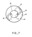
- This machining consists first of all in giving at the optical part 36 the shape required by machining its two surfaces S1 and S2. It also consists in machining the plate 20 in order to define the handles 38 and 40 in the particular example described.
- This machining includes moreover, in the event that there is network interpenetration between the two materials, the step of cutting out the periphery of the optical part 36 along line 45 to eliminate the interpenetration area that can be rigid.
- This cut shows the diameter D 'which is that of the part optics to achieve. This is the reason why the diameter D of the central recess 22 of the plate is greater than that of the part optical.
- An additional solution is to prime the surface of the orifice 22 or of the extensions 42 and 44 so as to obtain adhesion between the two materials.
- the optics will be flexible, either because the material chosen is hydrophilic and, in this case, it is its hydration which will have a role plasticizer; either because the material chosen has a temperature of glass transition below room temperature and in this case it will have been machined below this temperature.
- Figures 5 and 6 illustrate a variant mold for the realization of an intraocular implant, this variant concerning the way whose material is placed inside the mold cavity, this introduction no longer carried out by injection.
- this material can be an acrylic which, in this phase, is in the liquid form of a solution of monomers.
- This solution will have could be prepolymerized to obtain a syrup having a viscosity compatible with the removal of a drop 32 of this product.
- material exhibits a significant shrinkage during its transformation or "taken” to go from the liquid state to the solid state.
- the volume 32 deposited is significantly greater than the volume of the optics to be produced.
- This part 16 has a lower face having a central part which defines an area S2 limited by a closed contour C2.
- the surface S2 is an envelope of the second face of the optical part to be produced and the contour C2, preferably, coincides with the second upper contour C2 of the plate.
- Part 16 of mold also has a peripheral area which is preferably limited by a conical or frustoconical surface S'2.
- the upper part of the mold 16 is then lowered so that its closed contour C2 comes opposite the contour C'2 of the plate.
- the excess material 32 is expelled into the annular residual volume extending between the plate and the conical surface S'2 of the upper part 16 of the mold.
- the lowering is carried out in such a way that no air bubbles remain in the material.
- the angle at the apex a of the frustoconical portion 28 of the plate is greater than the angle at the apex b of the frustoconical surface S'2 of the upper part 16 of the mold.
- the stack formed by the lower part 14, the plate 20 and the upper part is kept under pressure.
- the ring 12 is used only for guiding and for the relative positioning of the two parts of the mold so that the closed contours C1, C2, C'1 and C'2 are actually opposite.
- the ring has no sealing function.
- the mold cavity is sealed by contacting the closed contours with pressure.
- the contact surface being very reduced, the formation, in the molded part, of parasitic parts in the two joint planes is avoided.
- the entire mold is then subjected to a treatment to cause the transformation of the material 32 from its initial liquid state to its final stable state at room temperature.
- the treatment may consist of a heat treatment or a bombardment with photons or with particles such as electrons.
- the material considered in this example it has a shrinkage. This is what is shown at 35 in FIG. 6.
- the optics to be achieved is limited by the surfaces S1 and S2 which are portions of the cap spherical in order to define the lens.
- the contours closed C1, C2, C'1, C'2 are circular.
- the surfaces S1 and S2 can be any, in particular concave or convex, and present the desired radius of curvature.
- one surfaces S1 could actually be planar.
- surfaces S1 and S2 could be more complex. We understand that the shape of the surfaces S1 and S2 does not in any way modify the different stages of the process.
- the principle of the method according to the invention consists in providing a plate of a second material intended to constitute the haptic part which is for example PMMA.
- This plate has a recess central whose periphery has exactly the shape of the periphery of the optical part.
- This plate has sufficient dimensions to allow the machining of the entire haptic part according to the techniques in themselves known.
- This plate is placed between the two parts of a mold which define in particular the two surfaces limiting the optical part. Is introduced into the cavity formed by the recess of the plate and the two parts of the mold a first material in the form liquid which has the required optical properties and which can be transformed to reach a solid end state.
- This material must have a phenomenon of withdrawal during this transformation substantially negligible. After carrying out the transformation of the material and having unmolded the product thus obtained, it suffices to machine the plate so as not to let remain of it as the desired haptic part.
- This second embodiment of the method uses a mold identical to that which has been described in connection with FIGS. 1, 4 and 5 and therefore will not be described again in detail.
- the implant for make the implant, we just place it inside the ring 12 and above from the lower part 14 a plate 20 which is produced in a material capable of forming the haptic part of the implant. Typically, for the reasons already indicated above, this material is PMMA preference. However, other types of materials.
- the outer contour of the plate 20 has the same diameter as the internal diameter of the ring 12.
- the plate 20 has an orifice central 22 whose diameter D is equal to the diameter of the optical part to achieve.
- the orifice 22 is therefore surrounded by a periphery 24, this periphery being itself limited by a first closed contour lower C'1 and by a second closed upper contour C'2.
- these contours are circular, of diameter D and they are arranged in parallel planes.
- the lower contour C'1 of the plate 20 coincides exactly with the closed contour C1 of the lower part of the mold 14.
- the periphery 24 of the orifice 22 has a thickness e which is strictly equal to the thickness of the contour of the optical part to be produced.
- the current part of the plate 20, which bears the reference 26, has a thickness e 'substantially greater than the thickness e of the wall 24. This thickness e 'is sufficient to allow the subsequent cutting of the haptic parts.
- the periphery 24 of the orifice 22 is connected to the current part 26 of the plate by two surfaces 28 and 30 which, in the case of the figure, are cone trunks but which, more generally depending on the shapes to be produced, could be portions of conical surface.
- the upper part of the mold 16 is then lowered in such a way so that its closed contour C2 comes exactly opposite the contour C'2 of the plate.
- the excess material 32 is driven into the annular residual volume extending between the plate and the conical surface S'2 of the upper part 16 of the mold.
- the lowering is carried out in such a way that no air bubbles remain in the material.
- the angle at the apex a of the frustoconical portion 28 of the plate is greater than the angle at the apex b of the frustoconical surface S'2 of the upper part 16 of the mold.
- the mold we keeps the stack formed by the lower part 14 under pressure, the plate 20 and the upper part 16. It is understood that the ring 12 only used for guiding and relative positioning of the two parts of the mold in such a way that the closed contours C1, C2, C'1 and C'2 are actually opposite.
- the ring has no function sealing.
- the mold footprint is sealed by the pressure contact of closed contours.
- the surface of contact being very reduced, the formation in the molded part is avoided parasitic parts in the two joint planes.
- the treatment may consist of a treatment thermal or in a bombardment by photons or by particles such as electrons.
- an additional solution is to pre-prepare the periphery 24 of the orifice 22 of the plate so as to produce a adhesion between the material constituting the haptic part and the material constituting the optical part 36.
- an implant is obtained intraocular which has an optical part 36 made of a material flexible and a haptic part constituted for example the handles 38 and 40 which have exactly the same mechanical properties and exactly the same shapes as the handles of the intraocular implants front monoblocks made for example of PMMA. Priming can be carried out on extensions 38 and 40 intended to serve as inserts for complete the connection between the two materials.
- the optics to be achieved is limited by the surfaces S1 and S2 which are portions of the cap spherical in order to define the lens.
- the contours closed C1, C2, C'1, C'2 are circular.
- the surfaces Si and S2 can be any, in particular concave or convex, and present the desired radius of curvature.
- one Si surfaces could actually be flat.
- surfaces S1 and S2 could be more complex. We understand that the shape of the surfaces S1 and S2 does not in any way modify the different stages of the process.
- the material used for the ring 20 is the PMMA.
- the material used to make the optical part in this second embodiment of the method, is a gel of silicone which has all the required properties and in particular a very low shrinkage during transformation.
- the silicone gels are polymerize with negligible volume variation. Gels silicone originating from the crosslinking of polydimethyl-siloxanes, polymethylphenylsiloxanes, polydiphenylsiloxanes and their copolymers suitable (the presence of phenyl functions allowing to increase the refractive index of the material).
- the copolymers of silicone with for example acrylics may be suitable.
- Polysiloxanes which can be used for the implementation of the invention are notably described in the following documents: EP-A-0 226 400, EP-A-0 556 040, WO-A-93/16660 and FR-A-2 587 896.
- EP-A-0 335 312 describes the formulation comprising a polysiloxane with vinyl endings and phenyl groups to increase the refractive index and a polysiloxane having hydride functions as well as a UV absorber which is only dispersed in the silicone. Aside from the dispersed UV filter, it's the same type of formulation that is used in the manufacture of all intraocular silicone implants. We prefer a UV filter linked to covalently with silicone.
- Thermoplastic materials can also be used. very low shrinkage and having the optical and biocompatibility required. These materials have the advantage of be able to be injected into the mold cavity.
- acrylic polymers concerned either belong to the hydrogel family, either have a temperature of glass transition (Tv) below ambient temperature.
- Tv temperature of glass transition
- a UV filter will be added to the polymer before crosslinking.
- the constituent material the optics is a silicone gel
- the method according to the second mode of implementation is particularly interesting. This material does not can be machined at room temperature or even at a temperature close to room temperature.
- the extensions 40 and 42 of plate 20 possibly combined with the other connection modes.
- these extensions provide anchoring very reliable mechanics of the ends of the haptic handles in the part optical.
Landscapes
- Health & Medical Sciences (AREA)
- Engineering & Computer Science (AREA)
- Ophthalmology & Optometry (AREA)
- Mechanical Engineering (AREA)
- Manufacturing & Machinery (AREA)
- Biomedical Technology (AREA)
- Animal Behavior & Ethology (AREA)
- Transplantation (AREA)
- Cardiology (AREA)
- Heart & Thoracic Surgery (AREA)
- Vascular Medicine (AREA)
- Life Sciences & Earth Sciences (AREA)
- Oral & Maxillofacial Surgery (AREA)
- General Health & Medical Sciences (AREA)
- Public Health (AREA)
- Veterinary Medicine (AREA)
- Prostheses (AREA)
- Moulds For Moulding Plastics Or The Like (AREA)
- Casting Or Compression Moulding Of Plastics Or The Like (AREA)
Description
- la figure 1 est une vue en coupe verticale d'un moule dans sa première position lors de l'élaboration de l'implant selon un premier mode de mise en oeuvre ;
- la figure 2 est une vue similaire montrant la mise en place de la deuxième partie du moule ;
- la figure 3 montre le moule en position fermée ;
- la figure 4 illustre le produit obtenu à la fin de l'étape de moulage et montre en partie l'opération d'usinage de la partie haptique ;
- les figures 5 et 6 montrent en coupe verticale une variante de réalisation du moule pour la mise en oeuvre du procédé selon une variante du premier mode de mise en oeuvre et selon un deuxième mode de mise en oeuvre ; et
- la figure 7 est une vue analogue à celle de la figure 4 pour le deuxième mode de mise en oeuvre de l'invention.
- d'une part, des anses taillées dans la partie 20, typiquement dans du PMMA,
- d'autre part, une optique usinée dans le matériau 32 injecté à l'intérieur du moule.
Claims (27)
- Procédé de réalisation d'un implant intraoculaire comprenant une partie optique définie par une première et une deuxième surface et par une périphérie limitée par des premier et deuxième contours fermés, chacun desdits contours limitant une desdites surfaces, ladite partie optique étant réalisée en un premier matériau souple, et une partie haptique réalisée en un deuxième matériau relativement rigide par rapport audit premier matériau, ledit procédé comprenant les étapes suivantes :on fournit un moule présentant une première (14) et une deuxième (16) partie de moule présentant chacune une face interne (S1, S2) définissant une surface limitée par un contour fermé (C1, C2) ;on fournit une plaque (20) du deuxième matériau présentant un évidement central (22) dont la périphérie a des dimensions supérieures ou éventuellement égales à celles de la périphérie de la partie optique envisagée, ladite plaque présentant au moins une portion d'ancrage (42, 44) faisant saillie à l'intérieur dudit évidement ;on dispose ladite plaque (20) entre lesdites première et deuxième parties (14, 16) de moule de telle manière (20) que les contours fermés desdites parties de moule soient en regard de ladite plaque, lesdites surfaces de parties de moule étant définies de telle manière que le volume limité par lesdites surfaces et ledit évidement de la plaque contienne au moins la forme de la partie optique envisagée ;on applique avec pression lesdites parties de moule sur ladite plaque, dans cette position lesdites surfaces des parties de moule définissant un volume dont la forme est une enveloppe de la partie optique à réaliser, et on dispose dans le volume défini par au moins ledit évidement et la surface de la partie inférieure du moule un volume dudit premier matériau sous forme liquide ;on applique audit premier matériau un traitement pour que celui-ci prenne son état solide, par quoi ladite portion d'ancrage constitue un insert à l'intérieur dudit premier matériau ;on démoule la pièce ainsi obtenue ; eton usine au moins ladite plaque pour obtenir la forme de partie haptique souhaitée.
- Procédé selon la revendication 1, dans lequel ledit premier matériau diminue de volume lors de son passage de l'état liquide à l'état solide caractérisé en ce que :on usine en outre ledit premier matériau pour lui donner la forme souhaitée d'optique.
- Procédé selon la revendication 2, caractérisé en ce qu'au moins une desdites parties du moule et/ou ladite plaque comporte au moins un orifice d'injection, en ce qu'on applique avec pression lesdites parties du moule sur ladite plaque de telle manière que l'évidement de ladite plaque et les surfaces des parties du moule forment une cavité étanche, et en ce qu'on injecte ledit premier matériau sous forme liquide dans ladite cavité à travers ledit orifice d'injection.
- Procédé selon la revendication 3, caractérisé en ce qu'au moins une desdites parties du moule et/ou ladite plaque comprend au moins un évent.
- Procédé selon la revendication 2, caractérisé en ce que ledit premier matériau présente une diminution de volume lors de sa transformation de l'état liquide à l'état solide et en ce que les surfaces des parties de moule sont des enveloppes des surfaces définissant la partie optique.
- Procédé selon l'une quelconque des revendications 2 à 5, caractérisé en ce que l'usinage dudit premier matériau comprend l'usinage desdites première et deuxième surfaces définissant la partie optique.
- Procédé selon l'une quelconque des revendications 2 à 6, caractérisé en ce que ledit premier matériau présente avec le deuxième matériau un phénomène d'interpénétration de réseau à leur interface et en ce que les dimensions de la périphérie de l'évidement de ladite plaque sont au moins égales à celles de la périphérie de la partie optique.
- Procédé selon la revendication 7, caractérisé en ce que l'usinage dudit premier matériau comprend la suppression, à la périphérie dudit premier matériau, de la zone annulaire ayant été le siège de phénomènes d'interpénétration de réseau entre les deux matériaux à l'exception des zones de raccordement de la partie haptique sur la périphérie de la partie optique.
- Procédé selon l'une quelconque des revendications 2 à 4, caractérisé en ce qu'on utilise un premier matériau présentant une diminution de volume négligeable lors de sa transformation de l'état liquide à l'état solide, en ce que lesdites surfaces des parties de moule sont identiques aux première et deuxième surfaces définissant la partie optique et la périphérie de l'évidement de ladite plaque est identique à la périphérie de la partie optique.
- Procédé selon la revendication 9, caractérisé en ce que l'usinage dudit premier matériau consiste au moins dans l'enlèvement du ou des points d'injection dudit matériau dans ladite cavité et du ou des évents.
- Procédé selon l'une quelconque des revendications 2 à 5, caractérisé en ce que ledit deuxième matériau est du PMMA et le premier matériau est un composé acrylique hydrophile.
- Procédé selon l'une quelconque des revendications 2 à 5, caractérisé en ce que ledit deuxième matériau est du PMMA et le premier matériau est un composé acrylique dont la température de transition vitreuse est suffisamment inférieure à la température ambiante.
- Procédé selon la revendication 2, caractérisé en ce que ledit premier matériau est disposé dans ladite cavité avant l'application desdites parties de moule sur ladite plaque, le volume dudit matériau étant supérieur à celui de la cavité résultant de l'application des parties de moule sur ladite plaque.
- Procédé selon la revendication 13, caractérisé en ce que lesdits premier et deuxième matériaux sont choisis pour réaliser une interpénétration de réseau entre lesdits matériaux lors de la transformation dudit premier matériau, par quoi on obtient une solidarisation de la périphérie de l'évidement de ladite plaque avec la périphérie de ladite partie optique et desdites portions d'ancrage dans ledit premier matériau.
- Procédé selon l'une quelconque des revendications 1 à 14, caractérisé en ce qu'on apprête lesdites portions d'ancrage pour réaliser l'adhérence des premier et second matériaux,
- Procédé selon la revendication 1 pour la réalisation d'un implant intraoculaire comprenant une partie optique (36) définie par deux portions de surfaces (S1, S2) et par une périphérie limitée par deux contours fermés (C'1, C'2), chaque contour fermé limitant une desdites surfaces, caractérisé en ce qu'il comprend les étapes suivantes:on fournit une partie inférieure de moule (14) présentant une surface supérieure dont la partie centrale (S1) correspondant à ladite première portion de surface limitée par ledit premier contour fermé (C1) et dont la partie périphérique (S1') est en retrait par rapport audit premier contour ;on fournit une plaque (20) réalisée avec ledit deuxième matériau présentant un évidement central (22) dont la périphérie (24) est limitée par lesdits premier (C'1) et deuxième (C'2) contours fermés, ladite plaque présentant au moins une portion d'ancrage (42, 44) faisant saillie à l'intérieur dudit évidement ;on dispose ladite plaque en regard de ladite partie inférieure du moule de telle manière que ledit contour fermé de ladite première partie soit en regard du premier contour fermé de ladite plaque ;on dispose au-dessus de ladite plaque une deuxième partie de moule (16) présentant une surface inférieure dont la partie centrale correspond à ladite deuxième portion de surface limitée par ledit deuxième contour fermé (C2) et dont la partie périphérique (S'2) est en retrait par rapport audit deuxième contour fermé, de telle manière que les deuxièmes contours fermés de ladite plaque et de la surface inférieure de la deuxième partie de moule soient en regard ;on introduit dans l'espace défini par au moins une desdites surfaces et par ledit évidement un volume (32) du premier matériau sous forme liquide au moins égal au volume de ladite partie optique ;on applique avec pression lesdites parties de moule de part et d'autre de ladite plaque de telle manière que respectivement les premiers contours fermés et les deuxièmes contours fermés entrent en contact mutuel par quoi ledit premier matériau remplit la totalité du volume limité par ledit évidement et lesdites portions de surface, l'excès éventuel dudit premier matériau étant chassé hors dudit volume;on soumet ledit premier matériau à un traitement pour assurer sa prise et l'amener dans son état final stable, par quoi ladite portion d'ancrage forme un insert à l'intérieur dudit premier matériau ;on démoule la pièce ainsi obtenue ; eton usine ladite plaque pour réaliser la forme souhaitée de la partie haptique (38, 40).
- Procédé selon la revendication 16, caractérisé en ce que lesdits premier et deuxième matériaux sont choisis pour réaliser une interpénétration de réseau entre lesdits matériaux lors de la transformation dudit premier matériau, par quoi on obtient une solidarisation de la périphérie de l'évidement de ladite plaque avec la périphérie de ladite partie optique et desdites portions d'ancrage dans ledit premier matériau.
- Procédé selon la revendication 16, caractérisé en ce qu'on apprête lesdites portions d'ancrage pour réaliser l'adhérence des premier et second matériaux.
- Procédé selon l'une quelconque des revendications 16 à 18, caractérisé en ce que ledit deuxième matériau est du PMMA.
- Procédé selon l'une quelconque des revendications 16 à 19, caractérisé en ce que ledit premier matériau est un polysiloxane.
- Procédé selon l'une quelconque des revendications 16 à 19, caractérisé en ce que ledit premier matériau est un matériau thermoplastique.
- Procédé selon l'une quelconque des revendications 16 à 19, caractérisé en ce que ledit premier matériau est un polymère acrylique de la famille des hydrogels.
- Procédé selon l'une quelconque des revendications 16 à 19, caractérisé en ce que ledit premier matériau est un polymère acrylique ayant une température de transition vitreuse inférieure à la température ambiante.
- Procédé selon l'une quelconque des revendications 11, 12 et 20 à 23, caractérisé en ce que ledit deuxième matériau comprend un agent de filtrage anti-UV lié par covalence.
- Procédé selon l'une quelconque des revendications 16 à 24, caractérisé en ce que lesdites première et deuxième portions de surface sont des calottes sphériques et en ce que lesdits premier et deuxième contours fermés sont deux cercles égaux et parallèles entre eux.
- Procédé selon la revendication 25, caractérisé en ce que ladite plaque présente une partie courante d'épaisseur e', en ce que la périphérie dudit évidement présente une épaisseur e < e', la partie courante étant raccordée à la périphérie dudit évidement par au moins une portion de surface conique (28, 30) de raccordement d'angle au sommet a.
- Procédé selon la revendication 26, caractérisé en ce que la partie périphérique de la partie de moule en regard de la face de la plaque présentant la surface conique de raccordement présente, au-delà dudit contour fermé circulaire une portion de surface conique présentant un angle au sommet b inférieur à l'angle au sommet a.
Applications Claiming Priority (5)
| Application Number | Priority Date | Filing Date | Title |
|---|---|---|---|
| FR9412274A FR2725659B1 (fr) | 1994-10-14 | 1994-10-14 | Procede de realisation d'un implant intraoculaire a optique souple |
| FR9412274 | 1994-10-14 | ||
| FR9412275A FR2725660A1 (fr) | 1994-10-14 | 1994-10-14 | Procede de realisation d'un implant intraoculaire a optique souple |
| FR9412275 | 1994-10-14 | ||
| PCT/FR1995/001344 WO1996011792A1 (fr) | 1994-10-14 | 1995-10-13 | Procede de realisation d'un implant intraoculaire a optique souple |
Publications (2)
| Publication Number | Publication Date |
|---|---|
| EP0734319A1 EP0734319A1 (fr) | 1996-10-02 |
| EP0734319B1 true EP0734319B1 (fr) | 2002-03-06 |
Family
ID=26231470
Family Applications (1)
| Application Number | Title | Priority Date | Filing Date |
|---|---|---|---|
| EP95934701A Expired - Lifetime EP0734319B1 (fr) | 1994-10-14 | 1995-10-13 | Procede de realisation d'un implant intraoculaire a optique souple |
Country Status (8)
| Country | Link |
|---|---|
| US (1) | US5762836A (fr) |
| EP (1) | EP0734319B1 (fr) |
| JP (1) | JPH09507183A (fr) |
| AT (1) | ATE213992T1 (fr) |
| CA (1) | CA2178910C (fr) |
| DE (1) | DE69525735T2 (fr) |
| ES (1) | ES2171557T3 (fr) |
| WO (1) | WO1996011792A1 (fr) |
Families Citing this family (45)
| Publication number | Priority date | Publication date | Assignee | Title |
|---|---|---|---|---|
| JP3779801B2 (ja) * | 1997-09-12 | 2006-05-31 | 株式会社メニコン | 眼内レンズの製造方法 |
| JPH11114979A (ja) * | 1997-10-15 | 1999-04-27 | Menicon Co Ltd | 眼用レンズ材料の成形装置及びそれを用いた成形方法 |
| AU751172B2 (en) * | 1997-12-02 | 2002-08-08 | Hoya Healthcare Corporation | Intraocular lenses and process for producing molded-in type intraocular lenses |
| US6429021B1 (en) * | 1998-03-19 | 2002-08-06 | Amway Corporation | Antioxidant activity profile assay |
| FR2779940B1 (fr) * | 1998-06-19 | 2000-11-03 | Ioltechnologie Production | Implant formant lentille intraoculaire monobloc bi-materiaux |
| US6450642B1 (en) | 1999-01-12 | 2002-09-17 | California Institute Of Technology | Lenses capable of post-fabrication power modification |
| US8556967B2 (en) | 1999-04-09 | 2013-10-15 | Faezeh Mona Sarfarazi | Interior bag for a capsular bag and injector |
| US6461384B1 (en) | 1999-06-17 | 2002-10-08 | Bausch & Lomb Incorporated | Intraocular lenses |
| US6391230B1 (en) | 2000-02-18 | 2002-05-21 | Bausch & Lomb Incorporated | Intraocular lens manufacturing process |
| EP1266256B1 (fr) | 2000-03-20 | 2006-06-21 | California Institute of Technology | Application de capteurs de front d'ondes sur des lentilles pouvant etre modifiees apres fabrication |
| JP2006289996A (ja) * | 2000-06-29 | 2006-10-26 | Toyo Tire & Rubber Co Ltd | 筒状芯体付成形品の成形型 |
| US7087080B2 (en) * | 2001-01-25 | 2006-08-08 | Visiogen, Inc. | Materials for use in intraocular lens system |
| US20030078658A1 (en) | 2001-01-25 | 2003-04-24 | Gholam-Reza Zadno-Azizi | Single-piece accomodating intraocular lens system |
| US6713081B2 (en) * | 2001-03-15 | 2004-03-30 | The United States Of America As Represented By The Department Of Health And Human Services | Ocular therapeutic agent delivery devices and methods for making and using such devices |
| US6929233B2 (en) * | 2001-03-16 | 2005-08-16 | Novartis Ag | Mold and method for casting ophthalmic lenses |
| ES2295344T3 (es) * | 2001-04-27 | 2008-04-16 | Eyesense Ag | Kit para medir concentraciones de glucosa en sangre. |
| US7115305B2 (en) * | 2002-02-01 | 2006-10-03 | California Institute Of Technology | Method of producing regular arrays of nano-scale objects using nano-structured block-copolymeric materials |
| US6939486B2 (en) * | 2002-06-25 | 2005-09-06 | Bausch & Lomb Incorporated | Apparatus and method for making intraocular lenses |
| AU2003297943A1 (en) * | 2002-12-20 | 2004-07-29 | Bausch & Lomb Incorporated | Apparatus and method for cutting an intraocular lense from a blank |
| US20040119175A1 (en) * | 2002-12-20 | 2004-06-24 | Reed Bryan M. | Apparatus and method for manufacturing intraocular lenses |
| DE10304724A1 (de) * | 2003-02-06 | 2004-08-26 | Landesstiftung Baden-Württemberg gGmbH | Vorrichtung zur Erhöhung der Schärfentiefe eines optischen Systems |
| US7217112B2 (en) * | 2003-05-27 | 2007-05-15 | Faezeh Mona Sarfarazi | Mold for intraocular lens |
| US20060038308A1 (en) * | 2003-06-26 | 2006-02-23 | Reed Bryan M | IOL square edge punch and haptic insertion fixture |
| EP1747576A2 (fr) * | 2004-05-05 | 2007-01-31 | California Institute of Technology | Lithographie capillaire de reseaux de nanofibres |
| US8057217B2 (en) | 2004-09-30 | 2011-11-15 | Bausch + Lomb Incorporated | Apparatus and method for injection molding an intraocular lens device |
| US8021967B2 (en) * | 2004-11-01 | 2011-09-20 | California Institute Of Technology | Nanoscale wicking methods and devices |
| JP4697786B2 (ja) * | 2005-08-23 | 2011-06-08 | セイコープレシジョン株式会社 | 可変焦点レンズとこれを用いた焦点調節装置及び撮像装置 |
| JP4923704B2 (ja) * | 2006-04-28 | 2012-04-25 | ソニー株式会社 | 光学素子の成形装置および成形方法 |
| WO2011101731A1 (fr) * | 2010-02-19 | 2011-08-25 | Inspire Ag, Irpd | Procédé et dispositif de fabrication d'un implant propre à un patient |
| JP5680877B2 (ja) * | 2010-05-06 | 2015-03-04 | 株式会社ニデック | 眼内レンズの製造方法及び該方法にて得られる眼内レンズ |
| WO2011159676A2 (fr) | 2010-06-14 | 2011-12-22 | The Regents Of The University Of Michigan | Identification in situ et contrôle de microstructures produites par transformation de phase d'un matériau |
| US10736732B2 (en) * | 2010-06-21 | 2020-08-11 | James Stuart Cumming | Intraocular lens with longitudinally rigid plate haptic |
| US9295545B2 (en) | 2012-06-05 | 2016-03-29 | James Stuart Cumming | Intraocular lens |
| TW201437725A (zh) * | 2013-03-21 | 2014-10-01 | Hon Hai Prec Ind Co Ltd | 背光模組及背光模組的製作方法 |
| US10098836B2 (en) | 2013-05-02 | 2018-10-16 | Retina Foundation Of The Southwest | Method for forming a molded two-layer ocular implant |
| CN106526720A (zh) * | 2016-12-20 | 2017-03-22 | 北京化工大学 | 聚合物凝胶眼球仿生变焦微透镜系统 |
| US12377622B2 (en) | 2019-04-05 | 2025-08-05 | Amo Groningen B.V. | Systems and methods for vergence matching with an optical profile and using refractive index writing |
| US11583389B2 (en) | 2019-04-05 | 2023-02-21 | Amo Groningen B.V. | Systems and methods for correcting photic phenomenon from an intraocular lens and using refractive index writing |
| US11944574B2 (en) | 2019-04-05 | 2024-04-02 | Amo Groningen B.V. | Systems and methods for multiple layer intraocular lens and using refractive index writing |
| US11678975B2 (en) | 2019-04-05 | 2023-06-20 | Amo Groningen B.V. | Systems and methods for treating ocular disease with an intraocular lens and refractive index writing |
| US11529230B2 (en) | 2019-04-05 | 2022-12-20 | Amo Groningen B.V. | Systems and methods for correcting power of an intraocular lens using refractive index writing |
| US12357509B2 (en) | 2019-04-05 | 2025-07-15 | Amo Groningen B.V. | Systems and methods for improving vision from an intraocular lens in an incorrect position and using refractive index writing |
| US11583388B2 (en) | 2019-04-05 | 2023-02-21 | Amo Groningen B.V. | Systems and methods for spectacle independence using refractive index writing with an intraocular lens |
| US11564839B2 (en) | 2019-04-05 | 2023-01-31 | Amo Groningen B.V. | Systems and methods for vergence matching of an intraocular lens with refractive index writing |
| JP7451879B2 (ja) * | 2019-05-16 | 2024-03-19 | 株式会社ニデック | 眼内レンズの製造方法 |
Family Cites Families (10)
| Publication number | Priority date | Publication date | Assignee | Title |
|---|---|---|---|---|
| FR1362588A (fr) * | 1963-04-23 | 1964-06-05 | Morvan Soc | Perfectionnement au traitement thermique, plus spécialement à la vulcanisation, insitu, de masses élastiques et notamment de joints d'étanchéité |
| JPS5794706A (en) * | 1980-12-04 | 1982-06-12 | Ricoh Co Ltd | Plate-like lens |
| GB2105866B (en) * | 1981-07-29 | 1985-05-09 | Lynell Med Tech Inc | Intraocular and extraocular lens construction and making by selective erosion |
| US4501715A (en) * | 1983-05-18 | 1985-02-26 | Gilbert Barfield | Mold and method for forming golf balls |
| JPH027954A (ja) * | 1988-03-04 | 1990-01-11 | Alcon Surgical Inc | 着色周辺部付きレンズの製造方法 |
| US5182053A (en) * | 1990-03-02 | 1993-01-26 | Optical Radiation Corporation | Process for forming intraocular lenses having haptics with high fracture toughness |
| US5074942A (en) * | 1990-05-15 | 1991-12-24 | Texceed Corporation | Method for making intraocular lens with integral colored haptics |
| US5217491A (en) * | 1990-12-27 | 1993-06-08 | American Cyanamid Company | Composite intraocular lens |
| FR2676358B1 (fr) * | 1991-05-17 | 1995-05-05 | Corneal | Dispositif intra-oculaire implantable dans le sac capsulaire. |
| FR2676357B1 (fr) * | 1991-05-17 | 1998-10-30 | Corneal | Dispositif intra-oculaire implantable dans le sac capsulaire. |
-
1995
- 1995-10-13 US US08/666,403 patent/US5762836A/en not_active Expired - Fee Related
- 1995-10-13 DE DE69525735T patent/DE69525735T2/de not_active Expired - Fee Related
- 1995-10-13 EP EP95934701A patent/EP0734319B1/fr not_active Expired - Lifetime
- 1995-10-13 ES ES95934701T patent/ES2171557T3/es not_active Expired - Lifetime
- 1995-10-13 AT AT95934701T patent/ATE213992T1/de active
- 1995-10-13 WO PCT/FR1995/001344 patent/WO1996011792A1/fr not_active Ceased
- 1995-10-13 JP JP8512995A patent/JPH09507183A/ja not_active Ceased
- 1995-10-13 CA CA002178910A patent/CA2178910C/fr not_active Expired - Fee Related
Also Published As
| Publication number | Publication date |
|---|---|
| EP0734319A1 (fr) | 1996-10-02 |
| ES2171557T3 (es) | 2002-09-16 |
| CA2178910A1 (fr) | 1996-04-25 |
| DE69525735T2 (de) | 2002-10-17 |
| DE69525735D1 (de) | 2002-04-11 |
| ATE213992T1 (de) | 2002-03-15 |
| CA2178910C (fr) | 2002-02-05 |
| WO1996011792A1 (fr) | 1996-04-25 |
| US5762836A (en) | 1998-06-09 |
| JPH09507183A (ja) | 1997-07-22 |
Similar Documents
| Publication | Publication Date | Title |
|---|---|---|
| EP0734319A1 (fr) | Procede de realisation d'un implant intraoculaire a optique souple | |
| EP0993281B1 (fr) | Implant intraoculaire | |
| EP0136201B1 (fr) | Procédé de raccordement de fibres optiques, et épissure optique obtenue | |
| KR100713574B1 (ko) | 콘텍트 렌즈 제조에 사용하는 몰드 | |
| US6315929B1 (en) | Mold assembly for forming ophthalmic lens, method of producing the same, and method of producing ophthalmic lens using the mold assembly | |
| EP0368751B1 (fr) | Lentille de contact diffractive gravée | |
| EP0035309B1 (fr) | Procédé de fabrication par moulage de lentille de contact et lentilles obtenues | |
| FR2666735A1 (fr) | Implant intra-oculaire a cavite interne. | |
| FR2883984A1 (fr) | Appareil pour conformer un film plan sur une lentille optique, procedes de fonctionnalisation d'une lentille optique au moyen dudit appareil, et lentille ainsi obtenue | |
| JPH0620761B2 (ja) | コンタクトレンズの成形 | |
| FR2600174A1 (fr) | Lentille spherique multifoyer en matiere plastique et procede pour la fabriquer | |
| FR2589352A1 (fr) | Lentille intraoculaire comportant des bords non eblouissants et son procede de fabrication | |
| FR2556211A1 (fr) | Lentille intracamerulaire souple et elastique et procede pour sa fabrication | |
| WO1999020206A1 (fr) | Dispositif d'implant intraoculaire | |
| EP0877584A1 (fr) | Dispositif de keratoprothese | |
| CN101909864A (zh) | 用于形成包括眼科器件在内的生物医学器件的浇注模具 | |
| FR2622835A1 (fr) | Procede et appareil de production d'articles moules,en materiaux thermodurcissables et thermoplastiques notamment pour des lentilles de contact a usage ophtalmique | |
| FR2655841A1 (fr) | Implant oculaire a deux constituants. | |
| EP0028975A1 (fr) | Dispositif pour la réalisation d'un verre composite, en particulier lentille ophtalmique | |
| EP1194283A1 (fr) | Procede de moulage de lentilles ophtalmiques | |
| EP1880827B1 (fr) | Procédé de thermoformage permettant l'obtention de formes complexes | |
| FR2725660A1 (fr) | Procede de realisation d'un implant intraoculaire a optique souple | |
| FR2725659A1 (fr) | Procede de realisation d'un implant intraoculaire a optique souple | |
| CA2362668A1 (fr) | Moules utilises pour la production de lentilles de contact | |
| EP0276331A1 (fr) | Implant intraoculaire de correction de l'aphakie |
Legal Events
| Date | Code | Title | Description |
|---|---|---|---|
| PUAI | Public reference made under article 153(3) epc to a published international application that has entered the european phase |
Free format text: ORIGINAL CODE: 0009012 |
|
| 17P | Request for examination filed |
Effective date: 19960612 |
|
| AK | Designated contracting states |
Kind code of ref document: A1 Designated state(s): AT BE CH DE DK ES FR GB IT LI NL SE |
|
| RAP1 | Party data changed (applicant data changed or rights of an application transferred) |
Owner name: CORNEAL LABORATOIRES |
|
| 17Q | First examination report despatched |
Effective date: 19981020 |
|
| GRAG | Despatch of communication of intention to grant |
Free format text: ORIGINAL CODE: EPIDOS AGRA |
|
| GRAG | Despatch of communication of intention to grant |
Free format text: ORIGINAL CODE: EPIDOS AGRA |
|
| GRAH | Despatch of communication of intention to grant a patent |
Free format text: ORIGINAL CODE: EPIDOS IGRA |
|
| GRAH | Despatch of communication of intention to grant a patent |
Free format text: ORIGINAL CODE: EPIDOS IGRA |
|
| REG | Reference to a national code |
Ref country code: GB Ref legal event code: IF02 |
|
| GRAA | (expected) grant |
Free format text: ORIGINAL CODE: 0009210 |
|
| AK | Designated contracting states |
Kind code of ref document: B1 Designated state(s): AT BE CH DE DK ES FR GB IT LI NL SE |
|
| PG25 | Lapsed in a contracting state [announced via postgrant information from national office to epo] |
Ref country code: NL Free format text: LAPSE BECAUSE OF FAILURE TO SUBMIT A TRANSLATION OF THE DESCRIPTION OR TO PAY THE FEE WITHIN THE PRESCRIBED TIME-LIMIT Effective date: 20020306 Ref country code: AT Free format text: LAPSE BECAUSE OF FAILURE TO SUBMIT A TRANSLATION OF THE DESCRIPTION OR TO PAY THE FEE WITHIN THE PRESCRIBED TIME-LIMIT Effective date: 20020306 |
|
| REF | Corresponds to: |
Ref document number: 213992 Country of ref document: AT Date of ref document: 20020315 Kind code of ref document: T |
|
| REG | Reference to a national code |
Ref country code: CH Ref legal event code: EP |
|
| REF | Corresponds to: |
Ref document number: 69525735 Country of ref document: DE Date of ref document: 20020411 |
|
| PG25 | Lapsed in a contracting state [announced via postgrant information from national office to epo] |
Ref country code: SE Free format text: LAPSE BECAUSE OF FAILURE TO SUBMIT A TRANSLATION OF THE DESCRIPTION OR TO PAY THE FEE WITHIN THE PRESCRIBED TIME-LIMIT Effective date: 20020606 Ref country code: DK Free format text: LAPSE BECAUSE OF FAILURE TO SUBMIT A TRANSLATION OF THE DESCRIPTION OR TO PAY THE FEE WITHIN THE PRESCRIBED TIME-LIMIT Effective date: 20020606 |
|
| GBT | Gb: translation of ep patent filed (gb section 77(6)(a)/1977) |
Effective date: 20020516 |
|
| NLV1 | Nl: lapsed or annulled due to failure to fulfill the requirements of art. 29p and 29m of the patents act | ||
| REG | Reference to a national code |
Ref country code: ES Ref legal event code: FG2A Ref document number: 2171557 Country of ref document: ES Kind code of ref document: T3 |
|
| PG25 | Lapsed in a contracting state [announced via postgrant information from national office to epo] |
Ref country code: LI Free format text: LAPSE BECAUSE OF NON-PAYMENT OF DUE FEES Effective date: 20021031 Ref country code: CH Free format text: LAPSE BECAUSE OF NON-PAYMENT OF DUE FEES Effective date: 20021031 Ref country code: BE Free format text: LAPSE BECAUSE OF NON-PAYMENT OF DUE FEES Effective date: 20021031 |
|
| PLBE | No opposition filed within time limit |
Free format text: ORIGINAL CODE: 0009261 |
|
| STAA | Information on the status of an ep patent application or granted ep patent |
Free format text: STATUS: NO OPPOSITION FILED WITHIN TIME LIMIT |
|
| 26N | No opposition filed |
Effective date: 20021209 |
|
| BERE | Be: lapsed |
Owner name: *CORNEAL LABORATOIRES Effective date: 20021031 |
|
| REG | Reference to a national code |
Ref country code: CH Ref legal event code: PL |
|
| PGFP | Annual fee paid to national office [announced via postgrant information from national office to epo] |
Ref country code: ES Payment date: 20071017 Year of fee payment: 13 Ref country code: DE Payment date: 20071010 Year of fee payment: 13 |
|
| PGFP | Annual fee paid to national office [announced via postgrant information from national office to epo] |
Ref country code: IT Payment date: 20071020 Year of fee payment: 13 |
|
| PGFP | Annual fee paid to national office [announced via postgrant information from national office to epo] |
Ref country code: GB Payment date: 20071016 Year of fee payment: 13 Ref country code: FR Payment date: 20071026 Year of fee payment: 13 |
|
| GBPC | Gb: european patent ceased through non-payment of renewal fee |
Effective date: 20081013 |
|
| REG | Reference to a national code |
Ref country code: FR Ref legal event code: ST Effective date: 20090630 |
|
| PG25 | Lapsed in a contracting state [announced via postgrant information from national office to epo] |
Ref country code: IT Free format text: LAPSE BECAUSE OF NON-PAYMENT OF DUE FEES Effective date: 20081013 Ref country code: DE Free format text: LAPSE BECAUSE OF NON-PAYMENT OF DUE FEES Effective date: 20090501 |
|
| PG25 | Lapsed in a contracting state [announced via postgrant information from national office to epo] |
Ref country code: FR Free format text: LAPSE BECAUSE OF NON-PAYMENT OF DUE FEES Effective date: 20081031 |
|
| PG25 | Lapsed in a contracting state [announced via postgrant information from national office to epo] |
Ref country code: GB Free format text: LAPSE BECAUSE OF NON-PAYMENT OF DUE FEES Effective date: 20081013 |
|
| REG | Reference to a national code |
Ref country code: ES Ref legal event code: FD2A Effective date: 20081014 |
|
| PG25 | Lapsed in a contracting state [announced via postgrant information from national office to epo] |
Ref country code: ES Free format text: LAPSE BECAUSE OF NON-PAYMENT OF DUE FEES Effective date: 20081014 |