EP0733765B1 - Section member and fitting assembly for making high thermal insulation wood coated window and door frames - Google Patents
Section member and fitting assembly for making high thermal insulation wood coated window and door frames Download PDFInfo
- Publication number
- EP0733765B1 EP0733765B1 EP96830118A EP96830118A EP0733765B1 EP 0733765 B1 EP0733765 B1 EP 0733765B1 EP 96830118 A EP96830118 A EP 96830118A EP 96830118 A EP96830118 A EP 96830118A EP 0733765 B1 EP0733765 B1 EP 0733765B1
- Authority
- EP
- European Patent Office
- Prior art keywords
- section member
- metal
- section
- members
- wood
- Prior art date
- Legal status (The legal status is an assumption and is not a legal conclusion. Google has not performed a legal analysis and makes no representation as to the accuracy of the status listed.)
- Revoked
Links
- 239000002023 wood Substances 0.000 title claims abstract description 50
- 238000009413 insulation Methods 0.000 title claims description 7
- 239000002184 metal Substances 0.000 claims abstract description 84
- 238000000576 coating method Methods 0.000 claims abstract description 38
- 230000000452 restraining effect Effects 0.000 claims abstract description 38
- 239000011248 coating agent Substances 0.000 claims abstract description 35
- 239000011810 insulating material Substances 0.000 claims abstract description 13
- 239000011521 glass Substances 0.000 claims description 24
- 239000000463 material Substances 0.000 claims description 8
- 238000007789 sealing Methods 0.000 claims description 7
- XLYOFNOQVPJJNP-UHFFFAOYSA-N water Substances O XLYOFNOQVPJJNP-UHFFFAOYSA-N 0.000 claims description 7
- 239000004677 Nylon Substances 0.000 claims description 2
- 229920001778 nylon Polymers 0.000 claims description 2
- 230000037431 insertion Effects 0.000 claims 1
- 238000003780 insertion Methods 0.000 claims 1
- 239000004033 plastic Substances 0.000 claims 1
- 229920003023 plastic Polymers 0.000 claims 1
- 230000015572 biosynthetic process Effects 0.000 description 3
- 230000002547 anomalous effect Effects 0.000 description 2
- 238000000034 method Methods 0.000 description 2
- 239000004952 Polyamide Substances 0.000 description 1
- 239000003795 chemical substances by application Substances 0.000 description 1
- 230000008878 coupling Effects 0.000 description 1
- 238000010168 coupling process Methods 0.000 description 1
- 238000005859 coupling reaction Methods 0.000 description 1
- 238000006073 displacement reaction Methods 0.000 description 1
- 230000000694 effects Effects 0.000 description 1
- 238000012986 modification Methods 0.000 description 1
- 230000004048 modification Effects 0.000 description 1
- 229920002647 polyamide Polymers 0.000 description 1
- 230000000284 resting effect Effects 0.000 description 1
Images


Classifications
-
- E—FIXED CONSTRUCTIONS
- E06—DOORS, WINDOWS, SHUTTERS, OR ROLLER BLINDS IN GENERAL; LADDERS
- E06B—FIXED OR MOVABLE CLOSURES FOR OPENINGS IN BUILDINGS, VEHICLES, FENCES OR LIKE ENCLOSURES IN GENERAL, e.g. DOORS, WINDOWS, BLINDS, GATES
- E06B3/00—Window sashes, door leaves, or like elements for closing wall or like openings; Layout of fixed or moving closures, e.g. windows in wall or like openings; Features of rigidly-mounted outer frames relating to the mounting of wing frames
- E06B3/30—Coverings, e.g. protecting against weather, for decorative purposes
- E06B3/301—Coverings, e.g. protecting against weather, for decorative purposes consisting of prefabricated profiled members or glass
- E06B3/303—Covering metal or plastic frames with wooden profiled members
-
- E—FIXED CONSTRUCTIONS
- E06—DOORS, WINDOWS, SHUTTERS, OR ROLLER BLINDS IN GENERAL; LADDERS
- E06B—FIXED OR MOVABLE CLOSURES FOR OPENINGS IN BUILDINGS, VEHICLES, FENCES OR LIKE ENCLOSURES IN GENERAL, e.g. DOORS, WINDOWS, BLINDS, GATES
- E06B3/00—Window sashes, door leaves, or like elements for closing wall or like openings; Layout of fixed or moving closures, e.g. windows in wall or like openings; Features of rigidly-mounted outer frames relating to the mounting of wing frames
- E06B3/04—Wing frames not characterised by the manner of movement
- E06B3/263—Frames with special provision for insulation
- E06B3/26301—Frames with special provision for insulation with prefabricated insulating strips between two metal section members
- E06B3/26303—Frames with special provision for insulation with prefabricated insulating strips between two metal section members with thin strips, e.g. defining a hollow space between the metal section members
-
- E—FIXED CONSTRUCTIONS
- E06—DOORS, WINDOWS, SHUTTERS, OR ROLLER BLINDS IN GENERAL; LADDERS
- E06B—FIXED OR MOVABLE CLOSURES FOR OPENINGS IN BUILDINGS, VEHICLES, FENCES OR LIKE ENCLOSURES IN GENERAL, e.g. DOORS, WINDOWS, BLINDS, GATES
- E06B3/00—Window sashes, door leaves, or like elements for closing wall or like openings; Layout of fixed or moving closures, e.g. windows in wall or like openings; Features of rigidly-mounted outer frames relating to the mounting of wing frames
- E06B3/04—Wing frames not characterised by the manner of movement
- E06B3/263—Frames with special provision for insulation
- E06B2003/26349—Details of insulating strips
- E06B2003/2635—Specific form characteristics
- E06B2003/26359—Specific form characteristics making flush mounting with neighbouring metal section members possible
-
- E—FIXED CONSTRUCTIONS
- E06—DOORS, WINDOWS, SHUTTERS, OR ROLLER BLINDS IN GENERAL; LADDERS
- E06B—FIXED OR MOVABLE CLOSURES FOR OPENINGS IN BUILDINGS, VEHICLES, FENCES OR LIKE ENCLOSURES IN GENERAL, e.g. DOORS, WINDOWS, BLINDS, GATES
- E06B3/00—Window sashes, door leaves, or like elements for closing wall or like openings; Layout of fixed or moving closures, e.g. windows in wall or like openings; Features of rigidly-mounted outer frames relating to the mounting of wing frames
- E06B3/04—Wing frames not characterised by the manner of movement
- E06B3/263—Frames with special provision for insulation
- E06B2003/26349—Details of insulating strips
- E06B2003/26387—Performing extra functions
- E06B2003/26389—Holding sealing strips or forming sealing abutments
Definitions
- the present invention relates to a section member and fitting assembly for making high thermal insulation wood coated window and door frames.
- window and door frames made of metal section members coated, on the side thereof provided for facing the inside environment, by wood strips.
- These door and window frames have the advantage of possessing a high mechanical strength and resistance against the weathering agents, and, moreover, they have advantageous aesthetic characteristics which can be compared with those of the door and window frames made of wood.
- the window or door frame is made of two materials which are very different from one another, it can be deformed because of the different thermal expansion of the metal section members and of the wood coating material.
- This anomalous deformations can negatively affect a proper connection of the movable frame of the door or window frame with the fixed frame thereof, so as to reduce the useful life of the frame.
- the aim of the present invention is to overcome the above mentioned problems, by providing a section member and fitting assembly for making high thermal insulation wood coated window and door frames which is specifically designed to greatly reduce the condensate formation on the metal section member side facing the inside environment and which, in particular, prevents the condensate from being absorbed by the wood coating material.
- a main object of the present invention is to provide such a section member and fitting assembly, in which the connection of the metal portions and wood coating does not generate any anomalous deformations caused by thermal expansion effects.
- Another object of the present invention is to provide such a section member and fitting assembly in which the wood coating on the inside portion of the frame section members can be carried out in a very simple and quick manner.
- Yet another object of the present invention is to provide such a section member and fitting assembly in which water is prevented from collecting inside the section members.
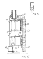
- the section member and fitting assembly for making high thermal insulation wood coated window and door frames comprises, as shown for example in figure 2, a fixed frame section member constituted by a metal outer section member 1 and a metal inner section member 2 which are connected to one another by thermally insulating material elements 3, 4.
- the metal inner section member 2 is provided, on the inner face or surface thereof, opposite to the metal outer section member 1, with a seat or recess 5 in which can be engaged restraining plugs 6, which can be affixed to a wood coating strip 7.
- the restraining plugs 6 are provided with a first portions 6a, which can be engaged in the seat 5 of the metal inner section member 2 and a second portion 6b which can be arranged between the inner face of the metal inner section member 2 and the wood coating strip 7 in order to hold said wood coating strip 7 spaced from the face of the section member 2 subjected to the inside environment.
- the seat 5 is defined by a pair of fins 8a and 8b, having a substantially L-shape configuration and opposite to one another, which extend on that side of the section member 2 provided for facing the inside environment.
- the restraining plug 6 is substantially constituted by the first portion 6a, having a substantially parallelepipedal configuration, and the second portion 6b, also having a substantially parallelepipedal configuration.
- Two opposite side corners of the portion 6a of the restraining plug 6 are suitably cut-out or beveled, so as to allow the restraining plug 6, after having engaged the first portion 6a in the seat 5, to tun in a plane which is substantially parallel to the laying plane of the face of the section member 2 facing te inside environment, so as to lock the restraining plug in the seat or recess 5.
- the coating wood strips 7 are affixed by applying a plurality of restraining plugs 6, for example by screws 10, spaced from one another on the face of the strip 7 provided for facing the section member 2.
- the screws 10 pass through a throughgoing hole 11, formed in the restraining plugs 6, so that, notwithstanding the application on the related strip 7, the several restraining plugs 6 can turn about the screw 10.
- the restraining plugs 6 are accordingly so oriented as to pass through the access opening of the seat 5 and, upon arranging inside the seat 5, they are turned, by a suitable not shown tool, through 90°, about the axis of the screw 10, so as to firmly engage said plugs inside the seat 5.
- the locking of the restraining plugs 6 in said seat 5 will allow anyhow to perform a sliding displacement of the restraining plugs 6 with respect to the section member 2, so as to prevent stresses from occurring between the section member 2 and wood strip 7 because of the different thermal expansions of the two materials of these elements.
- the elements 3 and 4 are formed by small bars which are preferably made of polyamide, and which can be made by an extruding method, and which are provided with enlarged thickness side end portions so as to engage in seats or recesses 12 formed by fins 13 projecting from the mutually facing section member 1 and 2 sides.
- the bars 3 and 4 have the portion thereof extending outside of the seats 12 which is bent away from an adjoining bar, so as to be substantially coplanar with the two fins 13 arranged outside of the bar pair 3 and 4.
- the section member assembly further comprises a glass restraining or detent section member 15 which can be bayonet locked on the metal inner section member 2.
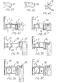
- the glass restraining section member 15 in particular, as is shown in figure 42, is provided with a lug 16 which can be engaged under a shoulder defined by a fin of the metal inner section member 2 and a fin 17 providing a resting or bearing portion 17a which can be abutted against a shoulder 18 defined by the section member 2.
- the glass restraining section member 15 is moreover provided, on the side thereof opposite to the glass panel or plate 19, with a fin 20 for supporting a wood coating strip 21.
- the metal outer section member 1 and glass restraining section member 15 face the two opposite surfaces of the glass panel or plate 19 and bear thereagainst, through the interposition of gaskets 22, 23.
- the glass restraining section member 15 will allow the wood strip 21 to be mounted, through the interposition of the gasket 24, and without using exposed to the view screws.
- one of the thermally insulating elements connecting to one another the metal outer section member 31 and metal inner section member 32, and which has been indicated in figure 4 by the reference number 4a, is provided with a fin 33 facing the fixed frame section member, for which the same reference number as those of figure 2 have been used, and thereagainst bears a sealing gasket 34 providing a connection between the fixed frame section member and the movable frame section member, of an open joint type, and being supported by the bar 4 arranged on the fixed frame section member.
- the frame made by the section member assembly according to the present invention has all of the metal inner section members arranged on a same side, with respect to the tightness or sealing plane identified by the coupling of the gasket 34 with the fin 33.
- the metal inner section members both of the fixed frame and of the movable frame are optimally insulated from the outer environment.
- the gasket 34 is so designed as to nearly fully coat the bar 4 to which it is connected, and so as to convey to the outside a possibly penetrated water.
- channels 35, 36, 37 and 38 are coupled to one another and with the outside environment by either vertical or horizontal holes, which have been not shown, therethrough the penetrated water is evacuated to the outside of the frame.
- an abutment gasket 48 can be arranged between the metal inner section member of the movable frame and the wood coating strip.
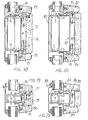
- Figures 5 and 6 illustrate, in cross-sectional views, the side of the movable-wing frame which is substantially made as the side shown in figure 4, with the difference that the wood coating strips 40, 41, 42, 43 have a different aesthetical configuration, with respect to the coating strips 44, 45 shown in figure 4.
- the metal outer section member 46, 47 has an aesthetic configuration different from that of the coating strips 44, 45 shown in figure 4.
- the metal outer section member 46, 47 has an aesthetic configuration different from that of the metal outer section member 31 of the movable frame shown in figure 4.
- Figure 7 illustrates a cross-sectional view of a frame upright, constituted by fixed frame section members and movable frame section members, which are the same section members shown in figure 4, and which have been indicated by the same reference numbers.
- Figure 8 illustrates a cross-sectional view of the central upright of a two-wing window, in which the outer top portion is formed by a section member 50 coupled to the metal inner and outer section members 31 and 32 of the movable frame.
- the section member 50 is also constituted by a metal outer section member 51 and a metal inner section member 52, which are connected to one another by bars 3 and 4.
- the metal inner section member 52 is coated, on its inner or inside face, by coating wood strips, of the type shown in figure 4 and which have been indicated by the same reference numbers.
- the side of the window frame shown in figures 9 and 10 can be considered analogous to that side of the window frame shown in figure 8, with the difference that in figure 9 have been used metal outer section members 46, of the type shown in figure 5 and, on the inner or inside side have been used covering strips 40, 41 and 7 like those shown in that same figure 5.
- section members 47 As metal outer section members have been used section members 47 and, on the inside side, have been used coating strips 42, 43 of the type shown in figure 6.
- Figure 12 is a cross-sectional view illustrating a central upright of a window constituted by a fixed portion and an openable portion.
- the movable frame is constituted by the same movable frame section members shown in figure 7, and the coating on the inside side is obtained by covering strips of the same type, and which have been indicated by the same reference number.
- the side of the fixed portion of the window frame is constituted by a metal outer section member 53, which is connected to a metal inner section member 54 by means of two bars 4.
- the bar 4 facing the movable frame is connected to a gasket or seal 34 bearing against a fin 33 of the bar 4a supported by the movable frame, as already disclosed with reference to figure 4.
- Figure 14 illustrates a cross sectional view of the lateral side of a door or window door including a fixed frame which is constituted by a metal outer section member 55 connected to the metal inner section member 56 by means of bars of a thermally insulating material 3 and 4.
- the movable frame is constituted by a metal outer section member 57 and a metal inner section member 58 which are connected to one another by means of thermally insulating material bars or rods 4a and 3.
- the inner side of the fixed frame and movable frame is coated by coating wood strips 59 and 60, which are connected to the metal inner section members 56 and 58 by plugs 6.
- Figure 15 illustrates a cross-sectional view of that same door or window-door, taken substantially at the bottom side.
- the movable frame is constituted by section members 57 and 58 with the addition, at the central portion of the door, of a further frame section member, also constituted by a metal outer section member 61 and a metal inner section member 52 which is coated, on its inner side, by a wood strip 63.
- section member 57 To the section member 57 is applied a "tile" section member 64, whereas the fixed frame section member is replaced by an open contour section member 65, on which is mounted the gasket or seal 34 engaging against the fin 33 of the bar or rod 4a assembled between the section members 57 and 58.
- the section member 65 is also subdivided into a portion 67 which is subjected to the inner or inside environment, and into a portion 68 which is affected by the outside environment, a bar or rod 4 on which is assembled the gasket 34 being arranged therebetween.
- Figure 17 illustrates a cross-sectional view of the bottom side of an access door which is constituted substantially by the same section members shown in figure 15 and for which the same reference numbers have been held, with the addition of a bottom box-like section member 69 provided with a tightness or sealing brush element 70.
- Figures 18 and 19 illustrates respective cross-sectional views of cross-members for a fixed type of window or door frames.
- figure 18 illustrates a section member constituted by an outer section member 71 and a metal inner section member 72 which are connected to one another by means of bars or rods 4 made of a thermally insulating material.
- inner metal section member 72 On the inner metal section member 72 are assembled two glass panel restraining section members 15, and the inner side of the metal inner section member 72 is coated by wood coating strips 73, 74, 75.
- Figure 19 illustrates a section member which is constituted by a metal outer section member 76 and a metal inner section member 77, connected to one another by bars or rods made of a thermally insulating material 4.
- the inner side of the metal inner section member 77 is coated by wood coating strips 78, 79, 80.
- Figure 20 illustrates a cross-sectional view of cross members for openable wings, which are constituted by a metal outer section member 80 and a metal inner section member 81 connected to one another by bars of a thermally insulating material 3.
- metal inner section member On the metal inner section member are assembled two glass panel restraining section member 15, and the inner side of the metal section members 81 is coated by wood strips 82, 83 and 84.
- Figure 21 illustrates a cross-sectional view of a cross member for openable wings, which is constituted by a metal outer section member 85, a metal inner section member 86 connected to one another by means of thermally insulating material bars or rods 3.
- the metal inner section member 86 is coated, on the inner side thereof, by coating wood strips indicated by the reference numbers 87, 88 and 89.
- FIGS 23 to 30 relate to details or features shown in figures which have been already disclosed and for which the same reference numbers have been used.
- the section member shown in figure 31 is also constituted by a metal outer section member 90 connected to a metal inner section member 91, by means of thermally insulating material bars or rods 3 and 4.
- the metal inner section member is coated, on the face thereof affected by the inside environment, by a wood strip 92 connected to the section member 91 by restraining plugs 6.
- Figures 32 to 37 are also related to section members or section member variations, which have been already disclosed with reference to the preceding figures, and for which the same reference numbers have been held.
- Figure 38 illustrates a further section member constituted by a metal outer section member 100 and a metal inner section member 101, connected to the metal outer section member by means of bars or rods 3 and 4a.
- the metal inner section member 101 is coated, on its inside or inner side, by a coating wood strip 102, coupled to the section member 101 by means of a restraining plug 106.
- Figures 39 and 40 relate to the fixed frame section member, already illustrated in figure 4 and figure 7, with the difference that the coating wood strips, indicated by the reference numbers 103 and 104, have been changed.
- FIGs 43 to 46 illustrate separately the wood strips, as transversely cross-sectioned, and already illustrated in the preceding figures at the reference numbers 40, 42, 21 and 44.
- the coating wood strip arranged on the inner or inside side of the metal inner section member is completely insulated from the metal section member since, in addition to the restraining plug 6, between the metal section member and wood strip is arranged a further gasket 108.
- section member and fitting assembly is susceptible to several modifications and variations, all of which will come within the scope of the invention.
- the used materials, as well as the contingent size and shapes, provided that they are compatible to the intended use can be any, depending on requirements.
Landscapes
- Engineering & Computer Science (AREA)
- Civil Engineering (AREA)
- Structural Engineering (AREA)
- Wing Frames And Configurations (AREA)
- Door And Window Frames Mounted To Openings (AREA)
- Securing Of Glass Panes Or The Like (AREA)
- Special Wing (AREA)
- Chemical And Physical Treatments For Wood And The Like (AREA)
Abstract
Description
- The present invention relates to a section member and fitting assembly for making high thermal insulation wood coated window and door frames.
- In recent years a great success has been encountered by window and door frames made of metal section members coated, on the side thereof provided for facing the inside environment, by wood strips. These door and window frames have the advantage of possessing a high mechanical strength and resistance against the weathering agents, and, moreover, they have advantageous aesthetic characteristics which can be compared with those of the door and window frames made of wood.
- However, in making window and door frames by using metal section members coated by wood strips several problems are encountered.
- At first, since the window or door frame is made of two materials which are very different from one another, it can be deformed because of the different thermal expansion of the metal section members and of the wood coating material.
- This anomalous deformations can negatively affect a proper connection of the movable frame of the door or window frame with the fixed frame thereof, so as to reduce the useful life of the frame.
- Another problem associated with the use of the above mentioned type of window or door frames is the formation of condensate, which is usually generated on the metal portion of the frame facing the inside environment and which, if absorbed by the wood portion, would progressively physically and aesthetically damage the coating strip thereby requesting the damaged strip to be frequently replaced. The document "Nuova Finestra" May 1994, page 124, shows a section member assembly having substantially the features of the preamble of
claim 1. - Accordingly, the aim of the present invention is to overcome the above mentioned problems, by providing a section member and fitting assembly for making high thermal insulation wood coated window and door frames which is specifically designed to greatly reduce the condensate formation on the metal section member side facing the inside environment and which, in particular, prevents the condensate from being absorbed by the wood coating material.
- Within the scope of the above mentioned aim, a main object of the present invention is to provide such a section member and fitting assembly, in which the connection of the metal portions and wood coating does not generate any anomalous deformations caused by thermal expansion effects.
- Another object of the present invention is to provide such a section member and fitting assembly in which the wood coating on the inside portion of the frame section members can be carried out in a very simple and quick manner.
- Yet another object of the present invention is to provide such a section member and fitting assembly in which water is prevented from collecting inside the section members.
- According to one aspect of the present invention, the above mentioned aim and objects, as well as yet other objects, which will become more apparent hereinafter, are achieved by a section member and fitting assembly for making high thermal insulation wood coated window and door frames, according to
claim 1. - Further characteristics and advantages of the section member and fitting assembly, according to the present invention, will become more apparent hereinafter from the following detailed disclosure of some preferred, though not exclusive, embodiment thereof, which are illustrated, by way of an indicative, but not limitative example, in the accompanying drawings, where:
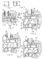
- Figure 1 schematically illustrates a fixed wing window frame;
- Figure 2 is an enlarged cross-sectional view of Figure 1, essentially taken along the section line II-II;
- Figure 3 schematically illustrates a movable wing window frame;
- Figure 4 is an enlarged cross-sectional view of Figure 3, essentially taken along the axis IV-IV;
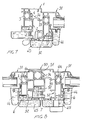
- Figures 5 and 6 are cross-sectional views analogous to Figure 4, with different aesthetic configurations of the exposed to the view portions of the section members constituting the frame;
- Figure 7 is an enlarged cross-sectional view of Figure 3, substantially taken along the section line VII-VII;
- Figure 8 is an enlarged cross-sectional view of Figure 3, substantially taken along the section line VIII-VIII;
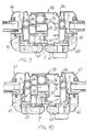
- Figures 9 and 10 are cross-sectional views analogous to Figure 8, and illustrating section members having, on the exposed to the view side thereof, a different aesthetic configuration;
- Figure 11 schematically illustrates a section member having a fixed wing and a movable wing;
- Figure 12 is an enlarged cross-sectional view of Figure 11, substantially taken along the section line XII-XII;
- Figure 13 is a schematic view illustrating a door or so-called window-door;
- Figure 14 is an enlarged cross-sectional view of Figure 13, taken substantially along the section line XIV-XIV;
- Figure 15 is an enlarged cross-sectional view of Figure 13, substantially taken along the section line XV-XV;
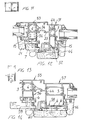
- Figure 16 schematically illustrates an inlet or access door;
- Figure 17 is an enlarged cross-sectional view of Figure 16, substantially taken along the section line XVII-XVII;
- Figures 18 and 19 are cross-sectional views illustrating fixed frame cross members;
- Figures 20 and 21 are cross-sectional views illustrating cross-members for movable frames, or for openable wings;
- Figure 22 illustrates the same cross member shown in Figure 18, from which have been removed the glass panels, the glass restraining section members and related seals and coatings;
- Figure 23 shows the same cross-member shown in Figure 19, the glass panels, glass restraining section members and related seal or gaskets and coatings being removed;
- Figure 24 illustrates the same cross-member shown in Figure 20, the glass panels, glass restraining section members and related gaskets and coating being removed;
- Figure 25 illustrates the same cross-member shown in Figure 21, the glass panels, glass restraining section members and related gaskets and coatings being removed;
- Figure 26 is a cross-sectional view illustrating a movable frame section member of the type shown in Figure 25;
- Figure 27 is another cross-sectional view illustrating a movable frame section member, of the type shown in Figure 26;
- Figure 28 is yet another cross-sectional view illustrating a movable frame section member, of the type shown in Figure 14;
- Figure 29 is yet another cross-sectional view illustrating a movable frame section member of the type shown in Figure 15;
- Figure 30 is yet another cross-sectional view illustrating a movable frame section member of the type shown in Figure 8;
- Figure 31 is yet another cross-sectional view illustrating a further section member;
- Figure 32 is yet another cross-sectional view illustrating the fixed frame section member being shown in Figure 2;
- Figure 33 is yet another cross-sectional view illustrating a fixed frame section member, of the type shown in Figure 4;
- Figure 34 is yet another cross-sectional view illustrating a movable frame section member of the type shown in Figure 4;
- Figure 35 is yet another cross-sectional view illustrating a fixed frame section member of the type shown in Figure 7;
- Figure 36 is yet another cross-sectional view illustrating a fixed frame section member of the type shown in Figure 14;
- Figure 37 is yet another cross-sectional view illustrating a section member of the type shown in Figure 37, with a different coating wood strip;
- Figure 38 is yet another cross-sectional view illustrating a further type of section member;
- Figures 39 and 40 are further crosssectional views illustrating fixed frame section members of the type shown in Figure 7, with a different type of assembled wood strip element;
- Figure 41 is a perspective view illustrating a restraining plug for the connection of the wood coating strip;
- Figure 42 is a cross-sectional view illustrating a glass restraining section member; and
- Figures 43, 44, 45 and 46 are cross-sectional views illustrating some wood strips for coating the faces of the section members provided from facing the inside environment of a room or the like.
-
- With reference to the number references of the figures of the accompanying drawings, the section member and fitting assembly for making high thermal insulation wood coated window and door frames according to the present invention comprises, as shown for example in figure 2, a fixed frame section member constituted by a metal
outer section member 1 and a metalinner section member 2 which are connected to one another by thermallyinsulating material elements - The metal
inner section member 2 is provided, on the inner face or surface thereof, opposite to the metalouter section member 1, with a seat orrecess 5 in which can be engagedrestraining plugs 6, which can be affixed to awood coating strip 7. - More specifically, the
restraining plugs 6 are provided with afirst portions 6a, which can be engaged in theseat 5 of the metalinner section member 2 and a second portion 6b which can be arranged between the inner face of the metalinner section member 2 and thewood coating strip 7 in order to hold saidwood coating strip 7 spaced from the face of thesection member 2 subjected to the inside environment. - More particularly, the
seat 5 is defined by a pair of fins 8a and 8b, having a substantially L-shape configuration and opposite to one another, which extend on that side of thesection member 2 provided for facing the inside environment. - As shown in particular in figure 41, the
restraining plug 6 is substantially constituted by thefirst portion 6a, having a substantially parallelepipedal configuration, and the second portion 6b, also having a substantially parallelepipedal configuration. - These portions are facing one another, are substantially parallel and are connected by a tapering region 6c.
- Two opposite side corners of the
portion 6a of therestraining plug 6 are suitably cut-out or beveled, so as to allow therestraining plug 6, after having engaged thefirst portion 6a in theseat 5, to tun in a plane which is substantially parallel to the laying plane of the face of thesection member 2 facing te inside environment, so as to lock the restraining plug in the seat or recess 5. - The
coating wood strips 7 are affixed by applying a plurality ofrestraining plugs 6, for example byscrews 10, spaced from one another on the face of thestrip 7 provided for facing thesection member 2. - The
screws 10 pass through athroughgoing hole 11, formed in therestraining plugs 6, so that, notwithstanding the application on therelated strip 7, theseveral restraining plugs 6 can turn about thescrew 10. - More specifically, the restraining plugs 6 are accordingly so oriented as to pass through the access opening of the
seat 5 and, upon arranging inside theseat 5, they are turned, by a suitable not shown tool, through 90°, about the axis of thescrew 10, so as to firmly engage said plugs inside theseat 5. - The locking of the restraining plugs 6 in said
seat 5 will allow anyhow to perform a sliding displacement of the restraining plugs 6 with respect to thesection member 2, so as to prevent stresses from occurring between thesection member 2 andwood strip 7 because of the different thermal expansions of the two materials of these elements. - Such a sliding possibility of the restraining plugs 6 and
section member 2 will be facilitated by the specifically designed configuration of the restraining plugs 6 and the material, preferably nylon, making them. - The
elements fins 13 projecting from the mutually facingsection member - The
bars seats 12 which is bent away from an adjoining bar, so as to be substantially coplanar with the twofins 13 arranged outside of thebar pair - Thus, a substantially continuous arrangement of the
fins 13 andbars - The section member assembly further comprises a glass restraining or
detent section member 15 which can be bayonet locked on the metalinner section member 2. - The glass
restraining section member 15, in particular, as is shown in figure 42, is provided with alug 16 which can be engaged under a shoulder defined by a fin of the metalinner section member 2 and afin 17 providing a resting or bearingportion 17a which can be abutted against ashoulder 18 defined by thesection member 2. - The glass
restraining section member 15 is moreover provided, on the side thereof opposite to the glass panel orplate 19, with a fin 20 for supporting awood coating strip 21. - The metal
outer section member 1 and glass restrainingsection member 15 face the two opposite surfaces of the glass panel orplate 19 and bear thereagainst, through the interposition ofgaskets - This connection of the glass restraining
section member 15 and metalinner section member 2 will provide a very good sealing property, the tightness of which increases as the pressure on the glass panel exerted from the outside toward the inside increases. - Moreover, owing to the provision of the fin 20, the glass restraining
section member 15 will allow thewood strip 21 to be mounted, through the interposition of the gasket 24, and without using exposed to the view screws. - Owing to the section member and fitting assembly according to the present invention, it is possible to make fixed type of window or door frames, or movable-wing window or door frames, or frames provided either with a fixed type or a movable type of wings, as is shown in the several figures of the drawings.
- For making movable wing window frames, one of the thermally insulating elements connecting to one another the metal
outer section member 31 and metalinner section member 32, and which has been indicated in figure 4 by thereference number 4a, is provided with afin 33 facing the fixed frame section member, for which the same reference number as those of figure 2 have been used, and thereagainst bears a sealinggasket 34 providing a connection between the fixed frame section member and the movable frame section member, of an open joint type, and being supported by thebar 4 arranged on the fixed frame section member. - The frame made by the section member assembly according to the present invention, as shown for example in figure 4, has all of the metal inner section members arranged on a same side, with respect to the tightness or sealing plane identified by the coupling of the
gasket 34 with thefin 33. - Thus, the metal inner section members both of the fixed frame and of the movable frame are optimally insulated from the outer environment.
- The
gasket 34 is so designed as to nearly fully coat thebar 4 to which it is connected, and so as to convey to the outside a possibly penetrated water. - Thus, because of this reason, laterally of the
bars section members channels - The above mentioned
channels - Between the metal inner section member of the movable frame and the wood coating strip an
abutment gasket 48 can be arranged. - Figures 5 and 6 illustrate, in cross-sectional views, the side of the movable-wing frame which is substantially made as the side shown in figure 4, with the difference that the wood coating strips 40, 41, 42, 43 have a different aesthetical configuration, with respect to the coating strips 44, 45 shown in figure 4.
- Likewise, the metal
outer section member - Likewise, the metal
outer section member outer section member 31 of the movable frame shown in figure 4. - Figure 7 illustrates a cross-sectional view of a frame upright, constituted by fixed frame section members and movable frame section members, which are the same section members shown in figure 4, and which have been indicated by the same reference numbers.
- Figure 8 illustrates a cross-sectional view of the central upright of a two-wing window, in which the outer top portion is formed by a
section member 50 coupled to the metal inner andouter section members - The
section member 50 is also constituted by a metal outer section member 51 and a metalinner section member 52, which are connected to one another bybars - The metal
inner section member 52 is coated, on its inner or inside face, by coating wood strips, of the type shown in figure 4 and which have been indicated by the same reference numbers. - The side of the window frame shown in figures 9 and 10 can be considered analogous to that side of the window frame shown in figure 8, with the difference that in figure 9 have been used metal
outer section members 46, of the type shown in figure 5 and, on the inner or inside side have been used coveringstrips - In figure 10, as metal outer section members have been used
section members 47 and, on the inside side, have been used coating strips 42, 43 of the type shown in figure 6. - Figure 12 is a cross-sectional view illustrating a central upright of a window constituted by a fixed portion and an openable portion.
- The movable frame is constituted by the same movable frame section members shown in figure 7, and the coating on the inside side is obtained by covering strips of the same type, and which have been indicated by the same reference number.
- The side of the fixed portion of the window frame is constituted by a metal
outer section member 53, which is connected to a metal inner section member 54 by means of twobars 4. - The
bar 4 facing the movable frame is connected to a gasket or seal 34 bearing against afin 33 of thebar 4a supported by the movable frame, as already disclosed with reference to figure 4. - For the several elements of figure 12 which are analogous to the already disclosed elements illustrated in the preceding figures, the same reference numbers have been used.
- Figure 14 illustrates a cross sectional view of the lateral side of a door or window door including a fixed frame which is constituted by a metal
outer section member 55 connected to the metalinner section member 56 by means of bars of a thermally insulatingmaterial - The movable frame is constituted by a metal
outer section member 57 and a metalinner section member 58 which are connected to one another by means of thermally insulating material bars orrods - The inner side of the fixed frame and movable frame is coated by coating wood strips 59 and 60, which are connected to the metal
inner section members plugs 6. - Figure 15 illustrates a cross-sectional view of that same door or window-door, taken substantially at the bottom side.
- The movable frame is constituted by
section members outer section member 61 and a metalinner section member 52 which is coated, on its inner side, by awood strip 63. - To the
section member 57 is applied a "tile"section member 64, whereas the fixed frame section member is replaced by an opencontour section member 65, on which is mounted the gasket or seal 34 engaging against thefin 33 of the bar orrod 4a assembled between thesection members - The
section member 65 is also subdivided into aportion 67 which is subjected to the inner or inside environment, and into aportion 68 which is affected by the outside environment, a bar orrod 4 on which is assembled thegasket 34 being arranged therebetween. - Figure 17 illustrates a cross-sectional view of the bottom side of an access door which is constituted substantially by the same section members shown in figure 15 and for which the same reference numbers have been held, with the addition of a bottom box-
like section member 69 provided with a tightness or sealing brush element 70. - Figures 18 and 19 illustrates respective cross-sectional views of cross-members for a fixed type of window or door frames.
- More specifically, figure 18 illustrates a section member constituted by an
outer section member 71 and a metalinner section member 72 which are connected to one another by means of bars orrods 4 made of a thermally insulating material. - On the inner
metal section member 72 are assembled two glass panel restrainingsection members 15, and the inner side of the metalinner section member 72 is coated by wood coating strips 73, 74, 75. - Figure 19 illustrates a section member which is constituted by a metal
outer section member 76 and a metalinner section member 77, connected to one another by bars or rods made of a thermally insulatingmaterial 4. - On the metal
inner section member 77 are assembled, even in this case, two glass panel restrainingsection members 15, of the above disclosed type. - The inner side of the metal
inner section member 77 is coated by wood coating strips 78, 79, 80. - Figure 20 illustrates a cross-sectional view of cross members for openable wings, which are constituted by a metal
outer section member 80 and a metalinner section member 81 connected to one another by bars of a thermally insulatingmaterial 3. - On the metal inner section member are assembled two glass panel restraining
section member 15, and the inner side of themetal section members 81 is coated bywood strips - Figure 21 illustrates a cross-sectional view of a cross member for openable wings, which is constituted by a metal
outer section member 85, a metalinner section member 86 connected to one another by means of thermally insulating material bars orrods 3. - The metal
inner section member 86 is coated, on the inner side thereof, by coating wood strips indicated by thereference numbers - Figures 23 to 30 relate to details or features shown in figures which have been already disclosed and for which the same reference numbers have been used.
- The section member shown in figure 31 is also constituted by a metal
outer section member 90 connected to a metalinner section member 91, by means of thermally insulating material bars orrods - The metal inner section member is coated, on the face thereof affected by the inside environment, by a
wood strip 92 connected to thesection member 91 by restraining plugs 6. - Figures 32 to 37 are also related to section members or section member variations, which have been already disclosed with reference to the preceding figures, and for which the same reference numbers have been held.
- Figure 38 illustrates a further section member constituted by a metal
outer section member 100 and a metalinner section member 101, connected to the metal outer section member by means of bars orrods - Even in this case, the metal
inner section member 101 is coated, on its inside or inner side, by acoating wood strip 102, coupled to thesection member 101 by means of a restraining plug 106. - Figures 39 and 40 relate to the fixed frame section member, already illustrated in figure 4 and figure 7, with the difference that the coating wood strips, indicated by the
reference numbers - Figures 43 to 46 illustrate separately the wood strips, as transversely cross-sectioned, and already illustrated in the preceding figures at the
reference numbers - Accordingly to the several shown assembling methods, the coating wood strip arranged on the inner or inside side of the metal inner section member, is completely insulated from the metal section member since, in addition to the restraining
plug 6, between the metal section member and wood strip is arranged afurther gasket 108. - From the above disclosure and the observation of the figures of the accompanying drawings, it should be apparent that the invention fully achieves the intended aim and objects.
- In particular, the fact is to be pointed out that a section member and fitting assembly has been provided, which allows to make window and door frames providing an optimum thermal insulation and which, because of this reason, greatly reduce the formation of condensate material on the section member side affected by the inner environment, and also preventing possible formed condensate from being absorbed by the wood coating.
- The thus disclosed section member and fitting assembly is susceptible to several modifications and variations, all of which will come within the scope of the invention.
- Moreover, all of the details can be replaced by other technically equivalent elements.
- In practicing the invention, the used materials, as well as the contingent size and shapes, provided that they are compatible to the intended use, can be any, depending on requirements.
Claims (9)
- A section member and fitting assembly for making high thermal insulation wood coated window and door frames, comprising fixed frame section members (1) and/or movable frame section members (2), each constituted by a metal outer section member and a metal inner section member, connected to one another by thermally insulating material elements (3, 4), said metal inner section member (2) being provided, on the inner face thereof opposite to said metal outer section member (1), with a seat (5) in which a plastics restraining plug (6) can be engaged, said restraining plug (6) being adapted to be fixed to a wood coating strip (7), said restraining plug (6) having a first portion (6a) thereof which can be engaged in said seat (5) and a second portion (6b) thereof which can be arranged between the inner face of the metal inner section member (2) and the wood coating strip, for spacing said wood coating strip (7) from said metal inner section member (2), characterized in that said seat (5) is defined by a pair of fins (8a, 8b) of the inner section member, having a substantially L-shape configuration and opposite to one another, said first portion (6a) of the plug (6) being provided for insertion through the open side of said seat (5) and being adapted to be locked in said seat (5) by causing said plug (6) to turn in a plane substantially parallel to the laying plane of the inner face of the inner section member (2), that the first portion (6a) and second portion (6b) of said plug (6) have substantially a parallelepipedal shape and being mutually facing one another, said first and second portions (6a, 6b) being connected by a tapering region (6c), and that said plug (6) is fixed to said wood coating strip (7) by a screw (10) passing through a central opening (11) in said plug (6).
- A section member and fitting assembly, according to Claim 1, characterized in that said plug (6) is made of nylon and can slide inside the seat (5) of the inner section member, in order to fit the different thermal expansion of said wood strip (7) and of said metal inner section member (2).
- A section member and fitting assembly, according to claims 1 and 2, characterized in that said thermally insulating material elements (3, 4) are constituted by pairs of adjoining bars (3, 4) engaging with their opposite end portions in pairs of seats (12) defined by fins (13), on the mutually facing sides of said inner section member (2) said bars (3, 4) having an outer portion outside of said seats (12) bent away from the adjoining bar in order to be substantially coplanar with two mutually facing fins (13).
- A section member and fitting assembly, according to one or more of the preceding claims, characterized in that said assembly further comprises glass panel restraining section members (15) which can be bayonet engaged on the fixed frame and/or movable frame section members (1, 2).
- A section member and fitting assembly, according to Claim 4, characterized in that said glass panel restraining section members (15) are provided, on the side thereof opposite to the glass panel, with a supporting fin (17) for supporting a coating wood strip (21).
- A window or door frame made by the section member and fitting assembly, according to one or more of the preceding claims, comprising a fixed frame and a movable frame, connected to one another and with an interposed sealing member (34) providing an open joint closure, characterized in that the metal inner section members (32) of the movable frame and fixed frame are all arranged toward the inner side of the window or door frame, with respect to the closure plane defined by the sealing member (34).
- A window or door frame, according to Claim 6, characterized in that the sealing member (34) is constituted by a central gasket (34), connected to said thermally insulated material bars, interposed between the metal inner section member (32) and metal outer section member (31) of the fixed frame section member, said central gasket (34) engaging against a fin (33) of the thermally insulating material bars (4a), arranged between metal inner section member (33) and metal outer section member (31) of the movable frame section member.
- A window or door frame, according to Claim 7, characterized in that the central gasket (34) substantially fully coats the face of the related thermally insulating bar (4a) to which it is connected, and the fins (33) of the adjoining section members with which said bar engages.
- A window or door frame, according to Claim 7, characterized in that in said metal outer section member (31), laterally of the region connected to the thermally insulating material bars (3,4,4a), are defined water collecting channels (35,36,37,38), said water collecting channels being coupled to one another and to the outside environment by perforations through the section members.
Applications Claiming Priority (2)
| Application Number | Priority Date | Filing Date | Title |
|---|---|---|---|
| IT95MI000550A IT1275942B1 (en) | 1995-03-20 | 1995-03-20 | COMPLEX OF PROFILES AND ACCESSORIES FOR THE CONSTRUCTION OF HIGH THERMAL INSULATION AND WOODEN-COVERED WINDOWS |
| ITMI950550 | 1995-03-20 |
Publications (2)
| Publication Number | Publication Date |
|---|---|
| EP0733765A1 EP0733765A1 (en) | 1996-09-25 |
| EP0733765B1 true EP0733765B1 (en) | 2000-01-19 |
Family
ID=11370981
Family Applications (1)
| Application Number | Title | Priority Date | Filing Date |
|---|---|---|---|
| EP96830118A Revoked EP0733765B1 (en) | 1995-03-20 | 1996-03-18 | Section member and fitting assembly for making high thermal insulation wood coated window and door frames |
Country Status (7)
| Country | Link |
|---|---|
| EP (1) | EP0733765B1 (en) |
| AT (1) | ATE189037T1 (en) |
| DE (1) | DE69606211T2 (en) |
| ES (1) | ES2144225T3 (en) |
| GR (1) | GR3033180T3 (en) |
| IL (1) | IL117558A (en) |
| IT (1) | IT1275942B1 (en) |
Families Citing this family (10)
| Publication number | Priority date | Publication date | Assignee | Title |
|---|---|---|---|---|
| IT1288999B1 (en) * | 1996-10-11 | 1998-09-25 | Archimede Progetti Srl | FRAME WITH METAL-INSULATION-METAL WOOD PROFILES IMPROVED |
| DE19716556C1 (en) * | 1997-04-19 | 1998-10-15 | Wolfgang Gesen | Window or door frame insulation |
| IT1311751B1 (en) * | 1999-03-17 | 2002-03-19 | Me Tra Metallurg Trafilati All | METALLIC PROFILES SYSTEM FOR THE MANUFACTURE OF COLORED FIXTURES, IN CORRESPONDENCE WITH THE INTERNAL SURFACES AND |
| ITBZ20090021A1 (en) * | 2009-05-06 | 2010-11-07 | Finstral Spa Ag | OUTDOOR WINDOW WITH HINGED FRAME AND FRAME ENCLOSURE MADE WITH PLASTIC / WOOD COMPOSITE PROFILES |
| BE1018779A5 (en) * | 2009-06-16 | 2011-08-02 | Renson Ventilation Nv | PROFILE CONFIRMATION SYSTEM. |
| CN103174361A (en) * | 2013-03-13 | 2013-06-26 | 辽宁德伟木业有限公司 | Composite section bar window body and manufacturing method |
| CN109972983B (en) * | 2017-12-27 | 2024-03-22 | 河北奥润顺达窗业有限公司 | Double-leaf metal plate outward opening door |
| CN110630141B (en) * | 2019-10-24 | 2024-06-18 | 北京金诺迪迈幕墙装饰工程有限公司 | Thermal-insulated reinforcing structure of heat preservation of high performance ground bullet door |
| AT523286B1 (en) * | 2020-09-02 | 2021-07-15 | Schneider Torsysteme Ges M B H | Gate frame attachment for a folding gate |
| CN114263413A (en) * | 2022-01-27 | 2022-04-01 | 浙江奥尚铝业有限公司 | Full-partition high-performance door and window structure and using method |
Family Cites Families (5)
| Publication number | Priority date | Publication date | Assignee | Title |
|---|---|---|---|---|
| ATE29758T1 (en) * | 1982-11-23 | 1987-10-15 | Wolfgang Zapp | FRAME CONSTRUCTION FOR GLAZED BUILDING OPENINGS, ESPECIALLY WINDOWS. |
| DE3343687A1 (en) * | 1983-11-30 | 1985-06-05 | Schweizerische Aluminium Ag, Chippis | METAL FRAME CONSTRUCTION FOR WINDOWS OR DOORS |
| SE468291B (en) * | 1990-06-20 | 1992-12-07 | Tema Foenster Ab | FRAMEWORK CONSTRUCTION |
| IT223556Z2 (en) * | 1991-03-13 | 1995-07-26 | Slim Soc Lavora Ind Metalli | SERIES OF MODULAR METAL PROFILES, FOR THE CONSTRUCTION OF EXTERNAL AND INTERNAL WINDOWS WITH A REDUCED NUMBER OF ACCESSORIES. |
| GB9217065D0 (en) * | 1992-08-12 | 1992-09-23 | Caradon Everest Ltd | Improvements in and relating to glazing assemblies |
-
1995
- 1995-03-20 IT IT95MI000550A patent/IT1275942B1/en active IP Right Grant
-
1996
- 1996-03-18 DE DE69606211T patent/DE69606211T2/en not_active Expired - Lifetime
- 1996-03-18 AT AT96830118T patent/ATE189037T1/en not_active IP Right Cessation
- 1996-03-18 EP EP96830118A patent/EP0733765B1/en not_active Revoked
- 1996-03-18 ES ES96830118T patent/ES2144225T3/en not_active Expired - Lifetime
- 1996-03-19 IL IL11755896A patent/IL117558A/en not_active IP Right Cessation
-
2000
- 2000-04-07 GR GR20000400873T patent/GR3033180T3/en not_active IP Right Cessation
Also Published As
| Publication number | Publication date |
|---|---|
| GR3033180T3 (en) | 2000-08-31 |
| DE69606211T2 (en) | 2000-08-10 |
| ITMI950550A1 (en) | 1996-09-20 |
| ATE189037T1 (en) | 2000-02-15 |
| IL117558A0 (en) | 1996-07-23 |
| ITMI950550A0 (en) | 1995-03-20 |
| DE69606211D1 (en) | 2000-02-24 |
| IL117558A (en) | 1998-12-27 |
| IT1275942B1 (en) | 1997-10-24 |
| ES2144225T3 (en) | 2000-06-01 |
| EP0733765A1 (en) | 1996-09-25 |
Similar Documents
| Publication | Publication Date | Title |
|---|---|---|
| EP0733765B1 (en) | Section member and fitting assembly for making high thermal insulation wood coated window and door frames | |
| US7150130B2 (en) | Sliding door assembly | |
| US4008552A (en) | Wall structure and elements therefor | |
| SK285095B6 (en) | Heat-insulated composite section for doors, windows, facades | |
| GB2111110A (en) | Frame assemblies for windows and doors | |
| JPH09209658A (en) | Fitting structure of batten for frame member | |
| AT511257B1 (en) | door leaf | |
| EP0733764B1 (en) | Cooperating section member assembly with thermal bridge interruptions for making improved thermal property metal window and door frames | |
| IL100000A (en) | Section member assembly for making sliding wing window frames | |
| US11118807B2 (en) | Door assembly, air handling unit comprising such a door assembly, and method for manufacturing such a door assembly | |
| JP3069310B2 (en) | Insulated profile | |
| CN110469239A (en) | A kind of aluminum alloy doors and windows | |
| US20200238795A1 (en) | Window assembly having flush frame to sash | |
| WO2019130367A1 (en) | Window frame | |
| EP0897437B1 (en) | Connection for a window system | |
| GB2392196A (en) | Glazing frame with oppositely facing rebates and mullion joined to frame by seperate connector | |
| CN210483447U (en) | Full aluminum alloy anti-theft entrance door | |
| PL181495B1 (en) | Door leaf, window casement or the like | |
| KR101933354B1 (en) | Insulating fire door with support bar for reinforce | |
| CN222835623U (en) | A corner structure suitable for window screen integrated thermal break window | |
| CN218150457U (en) | Novel integrated structure of mullion-free split window screen | |
| GB2143270A (en) | Window or door frame | |
| KR102767098B1 (en) | Exposed insulated windows with improved insulation | |
| CN222731458U (en) | Profile structure capable of opening aluminum alloy grille | |
| JPH07111113B2 (en) | Frame for joinery |
Legal Events
| Date | Code | Title | Description |
|---|---|---|---|
| PUAI | Public reference made under article 153(3) epc to a published international application that has entered the european phase |
Free format text: ORIGINAL CODE: 0009012 |
|
| AK | Designated contracting states |
Kind code of ref document: A1 Designated state(s): AT BE CH DE DK ES FI FR GB GR IE IT LI LU MC NL PT SE |
|
| 17P | Request for examination filed |
Effective date: 19961223 |
|
| 17Q | First examination report despatched |
Effective date: 19980623 |
|
| GRAG | Despatch of communication of intention to grant |
Free format text: ORIGINAL CODE: EPIDOS AGRA |
|
| GRAG | Despatch of communication of intention to grant |
Free format text: ORIGINAL CODE: EPIDOS AGRA |
|
| GRAH | Despatch of communication of intention to grant a patent |
Free format text: ORIGINAL CODE: EPIDOS IGRA |
|
| GRAH | Despatch of communication of intention to grant a patent |
Free format text: ORIGINAL CODE: EPIDOS IGRA |
|
| GRAA | (expected) grant |
Free format text: ORIGINAL CODE: 0009210 |
|
| AK | Designated contracting states |
Kind code of ref document: B1 Designated state(s): AT BE CH DE DK ES FI FR GB GR IE IT LI LU MC NL PT SE |
|
| PG25 | Lapsed in a contracting state [announced via postgrant information from national office to epo] |
Ref country code: SE Free format text: THE PATENT HAS BEEN ANNULLED BY A DECISION OF A NATIONAL AUTHORITY Effective date: 20000119 Ref country code: NL Free format text: LAPSE BECAUSE OF FAILURE TO SUBMIT A TRANSLATION OF THE DESCRIPTION OR TO PAY THE FEE WITHIN THE PRESCRIBED TIME-LIMIT Effective date: 20000119 Ref country code: LI Free format text: LAPSE BECAUSE OF FAILURE TO SUBMIT A TRANSLATION OF THE DESCRIPTION OR TO PAY THE FEE WITHIN THE PRESCRIBED TIME-LIMIT Effective date: 20000119 Ref country code: IT Free format text: LAPSE BECAUSE OF FAILURE TO SUBMIT A TRANSLATION OF THE DESCRIPTION OR TO PAY THE FEE WITHIN THE PRESCRIBED TIME-LIMIT;WARNING: LAPSES OF ITALIAN PATENTS WITH EFFECTIVE DATE BEFORE 2007 MAY HAVE OCCURRED AT ANY TIME BEFORE 2007. THE CORRECT EFFECTIVE DATE MAY BE DIFFERENT FROM THE ONE RECORDED. Effective date: 20000119 Ref country code: FI Free format text: LAPSE BECAUSE OF FAILURE TO SUBMIT A TRANSLATION OF THE DESCRIPTION OR TO PAY THE FEE WITHIN THE PRESCRIBED TIME-LIMIT Effective date: 20000119 Ref country code: CH Free format text: LAPSE BECAUSE OF FAILURE TO SUBMIT A TRANSLATION OF THE DESCRIPTION OR TO PAY THE FEE WITHIN THE PRESCRIBED TIME-LIMIT Effective date: 20000119 |
|
| REF | Corresponds to: |
Ref document number: 189037 Country of ref document: AT Date of ref document: 20000215 Kind code of ref document: T |
|
| REG | Reference to a national code |
Ref country code: CH Ref legal event code: EP |
|
| REF | Corresponds to: |
Ref document number: 69606211 Country of ref document: DE Date of ref document: 20000224 |
|
| REG | Reference to a national code |
Ref country code: IE Ref legal event code: FG4D |
|
| PG25 | Lapsed in a contracting state [announced via postgrant information from national office to epo] |
Ref country code: LU Free format text: LAPSE BECAUSE OF NON-PAYMENT OF DUE FEES Effective date: 20000318 |
|
| PG25 | Lapsed in a contracting state [announced via postgrant information from national office to epo] |
Ref country code: IE Free format text: LAPSE BECAUSE OF NON-PAYMENT OF DUE FEES Effective date: 20000320 |
|
| PG25 | Lapsed in a contracting state [announced via postgrant information from national office to epo] |
Ref country code: PT Free format text: LAPSE BECAUSE OF FAILURE TO SUBMIT A TRANSLATION OF THE DESCRIPTION OR TO PAY THE FEE WITHIN THE PRESCRIBED TIME-LIMIT Effective date: 20000419 Ref country code: GB Free format text: LAPSE BECAUSE OF NON-PAYMENT OF DUE FEES Effective date: 20000419 Ref country code: DK Free format text: LAPSE BECAUSE OF FAILURE TO SUBMIT A TRANSLATION OF THE DESCRIPTION OR TO PAY THE FEE WITHIN THE PRESCRIBED TIME-LIMIT Effective date: 20000419 |
|
| ET | Fr: translation filed | ||
| REG | Reference to a national code |
Ref country code: ES Ref legal event code: FG2A Ref document number: 2144225 Country of ref document: ES Kind code of ref document: T3 |
|
| NLV1 | Nl: lapsed or annulled due to failure to fulfill the requirements of art. 29p and 29m of the patents act | ||
| REG | Reference to a national code |
Ref country code: CH Ref legal event code: PL |
|
| PG25 | Lapsed in a contracting state [announced via postgrant information from national office to epo] |
Ref country code: MC Free format text: LAPSE BECAUSE OF NON-PAYMENT OF DUE FEES Effective date: 20000930 |
|
| PLBQ | Unpublished change to opponent data |
Free format text: ORIGINAL CODE: EPIDOS OPPO |
|
| PLBI | Opposition filed |
Free format text: ORIGINAL CODE: 0009260 |
|
| PLBF | Reply of patent proprietor to notice(s) of opposition |
Free format text: ORIGINAL CODE: EPIDOS OBSO |
|
| GBPC | Gb: european patent ceased through non-payment of renewal fee |
Effective date: 20000419 |
|
| 26 | Opposition filed |
Opponent name: SCHUECO INTERNATIONAL KG Effective date: 20001018 |
|
| REG | Reference to a national code |
Ref country code: IE Ref legal event code: MM4A |
|
| PLBF | Reply of patent proprietor to notice(s) of opposition |
Free format text: ORIGINAL CODE: EPIDOS OBSO |
|
| PGFP | Annual fee paid to national office [announced via postgrant information from national office to epo] |
Ref country code: FR Payment date: 20010308 Year of fee payment: 6 |
|
| PGFP | Annual fee paid to national office [announced via postgrant information from national office to epo] |
Ref country code: ES Payment date: 20010315 Year of fee payment: 6 |
|
| PGFP | Annual fee paid to national office [announced via postgrant information from national office to epo] |
Ref country code: GR Payment date: 20010330 Year of fee payment: 6 |
|
| PLBF | Reply of patent proprietor to notice(s) of opposition |
Free format text: ORIGINAL CODE: EPIDOS OBSO |
|
| PGFP | Annual fee paid to national office [announced via postgrant information from national office to epo] |
Ref country code: BE Payment date: 20020228 Year of fee payment: 7 |
|
| PGFP | Annual fee paid to national office [announced via postgrant information from national office to epo] |
Ref country code: AT Payment date: 20020314 Year of fee payment: 7 |
|
| PGFP | Annual fee paid to national office [announced via postgrant information from national office to epo] |
Ref country code: DE Payment date: 20020316 Year of fee payment: 7 |
|
| PG25 | Lapsed in a contracting state [announced via postgrant information from national office to epo] |
Ref country code: ES Free format text: LAPSE BECAUSE OF NON-PAYMENT OF DUE FEES Effective date: 20020320 |
|
| RDAH | Patent revoked |
Free format text: ORIGINAL CODE: EPIDOS REVO |
|
| RDAG | Patent revoked |
Free format text: ORIGINAL CODE: 0009271 |
|
| STAA | Information on the status of an ep patent application or granted ep patent |
Free format text: STATUS: PATENT REVOKED |
|
| 27W | Patent revoked |
Effective date: 20020721 |