EP0733580A2 - Running gear having damped pendulum oscillations - Google Patents
Running gear having damped pendulum oscillations Download PDFInfo
- Publication number
- EP0733580A2 EP0733580A2 EP96103256A EP96103256A EP0733580A2 EP 0733580 A2 EP0733580 A2 EP 0733580A2 EP 96103256 A EP96103256 A EP 96103256A EP 96103256 A EP96103256 A EP 96103256A EP 0733580 A2 EP0733580 A2 EP 0733580A2
- Authority
- EP
- European Patent Office
- Prior art keywords
- speed
- electric drive
- drive according
- state
- electronic control
- Prior art date
- Legal status (The legal status is an assumption and is not a legal conclusion. Google has not performed a legal analysis and makes no representation as to the accuracy of the status listed.)
- Withdrawn
Links
Images


Classifications
-
- B—PERFORMING OPERATIONS; TRANSPORTING
- B66—HOISTING; LIFTING; HAULING
- B66C—CRANES; LOAD-ENGAGING ELEMENTS OR DEVICES FOR CRANES, CAPSTANS, WINCHES, OR TACKLES
- B66C13/00—Other constructional features or details
- B66C13/04—Auxiliary devices for controlling movements of suspended loads, or preventing cable slack
- B66C13/06—Auxiliary devices for controlling movements of suspended loads, or preventing cable slack for minimising or preventing longitudinal or transverse swinging of loads
- B66C13/063—Auxiliary devices for controlling movements of suspended loads, or preventing cable slack for minimising or preventing longitudinal or transverse swinging of loads electrical
-
- B—PERFORMING OPERATIONS; TRANSPORTING
- B66—HOISTING; LIFTING; HAULING
- B66C—CRANES; LOAD-ENGAGING ELEMENTS OR DEVICES FOR CRANES, CAPSTANS, WINCHES, OR TACKLES
- B66C13/00—Other constructional features or details
- B66C13/18—Control systems or devices
- B66C13/22—Control systems or devices for electric drives
- B66C13/30—Circuits for braking, traversing, or slewing motors
Definitions
- the chassis equipped with an asynchronous motor accelerates quickly and changes to a constant driving speed after a short driving distance.
- the consequence of the jerky acceleration of the undercarriage is that the load hanging on the extended chain begins to oscillate and the oscillation does not stop even when the undercarriage is moving at a constant speed moved on.
- the movement of the load can be broken down into two components, namely a uniform movement in the direction of travel and an oscillating movement which tends to alternately decelerate or accelerate the undercarriage. Because of the hard characteristic of the asynchronous motor, the undercarriage cannot follow this force induced by the pendulum motion, which is why the undercarriage acts like a rigid, fixed suspension for the pendulum motion component.
- the undercarriage can follow the pendulum movement because when the load swings forward, the undercarriage can follow the load.
- the undercarriage is accelerated by the motor when the hook load is at rest, the undercarriage has already moved a considerable distance from the rest position before the load hanging on the hook is accelerated in the direction of travel. If a jerky acceleration occurs from standstill, a load oscillation is induced by the jerky acceleration. As a result of the load oscillation, the load will endeavor to run ahead of the chassis after a certain travel distance of the chassis, i.e. the swinging load in turn pulls the undercarriage and tries to accelerate it. In contrast to simple asynchronous motors, the chassis equipped with the new drive system can follow this acceleration caused by the load swinging. In this way, the energy contained in the oscillating load is converted into driving energy that keeps the running gear moving.
- Such a drive characteristic can be achieved either by means of an asynchronous motor with freewheeling or with the aid of a motor with a main closing characteristic. This is because the motor with the main fault characteristic cannot act as a brake, because there is no speed at which a generator effect can occur as long as the polarity between the armature and the field winding is not changed.
- the universal motor working in the main circuit has a very soft speed-torque characteristic.
- the load oscillation is reduced in any case in a chassis with a regulated universal motor as the drive, because this type of drive reduces jerky accelerations.
- the flexibility of the travel drive can be further increased if the switch arrangement has at least a third switching state in which the power supply to the motor is possible. Either a further rigid driving speed or the "accelerate" operating state can be assigned to this third switching state.
- the undercarriage can then be operated at least with two different speeds of a fixed size or else with a stepless speed setting that can be increased up to a maximum speed.
- the direction of travel can also be reversed with any type of motor if the running gear is to be bidirectional.
- the switch arrangement is equipped with either only one or with two further switch positions, so that the same possibilities with regard to the driving speed are available in every direction of travel.
- the switch arrangement can be operated remotely from a higher-level process control, for example when the hoist is running in a largely automated system, or there is the possibility of transferring the switch arrangement into the different switching positions via a manually operated actuator. In the latter case, it is a push button switch arrangement, as is usually used in control bulbs of hoists.
- the undercarriage or the motor has a speed sensor that is connected to the electronic control system and that transmits a signal proportional to the vehicle speed to the electronic control system.
- phase control can also be viewed as a kind of pulse width modulation with a fixed clock frequency, which is predetermined by the network frequency.
- the regulation of the motor speed in a motor with a main closing characteristic can be carried out either with the aid of a proportional regulator or with the aid of an integral regulator.
- the latter has the main advantage that no residual error remains when the leveling is corrected.
- controller can be constructed at any time using discrete physical components, it is expedient to implement the controller on the basis of a microprocessor, which means that the controller itself works incrementally.
- control characteristics can be generated that are difficult or impossible to implement with discrete components.
- certain unpleasant properties of integral controllers such as slow response or starting with the wrong initial value, can be easily eliminated.
- an initial value is assigned to the controller, which inevitably comes into effect when the undercarriage is started from a standstill.
- This initial value does not necessarily have to be identical to the steps by which the value of the controller or the state of the controller is incremented if, after the first switching on of the operation, the desired control in the sense of keeping the speed constant or reaching a desired speed is activated is.
- the current flow angle Since usually the current flow angle becomes larger faster than the undercarriage can accelerate, the current flow angle will be larger when it reaches the nominal speed than is necessary to keep this speed reached constant.
- the state of the controller after the first exceeding of the set speed is expediently reduced by a value which in turn is expediently greater than the incremental value with which the controller otherwise works in normal operation.
- the controller works with different or larger jumps than in normal operation, if one Operational situation change occurs, which is ultimately caused by a change in the switch position.
- a setpoint generator is used, which can assume different values depending on the switch position.
- the setpoint generator In the case of acceleration from standstill or an existing driving speed, the setpoint generator is set to a value that corresponds to the maximum possible or a higher speed.
- the value of the setpoint generator is converted to the current speed value, so that the controller can orientate itself from this setpoint until the next adjustment is arranged becomes.
- a delay i.e. the decrease in driving speed towards a lower speed.
- Fig. 1 shows a schematic representation of a mechanical embodiment of a drive system for the carriage of a hoist, for example a trolley, as used in floor-free conveyors.
- the drive system has an asynchronous motor 1 which only runs in one direction, the output shaft 2 of which is mechanically coupled to a schematically illustrated freewheel 3.
- the freewheel 3 On the output side, the freewheel 3 is connected to an input shaft 4 of a reduction gear 5, the output shaft 6 of which is in turn non-rotatably coupled to one of the drive wheels 7.
- the drive wheel 7 runs on a schematically shown rail 8.
- a control switch not shown, is used to ensure that the drive motor 1 is supplied with electrical energy, it begins to rotate, specifically with the design direction of rotation. He drives the input shaft 4 of the transmission 5 via the freewheel 3, which in this direction is non-positively coupled, and which then sets the drive wheel 7 in motion.
- the chassis is accelerated relatively abruptly. This strong acceleration cannot be followed by the load hanging on the load suspension device in the form of a rope or a chain, which is why it will initially lag behind the running gear.
- the asynchronous motor 1 After a time dependent on the conditions, the asynchronous motor 1 reaches its nominal speed, which means that from now on the running gear will travel along the running rail 8 at a constant speed.
- the load initially lagging the movement of the undercarriage forms a pendulum under the undercarriage traveling at constant speed, which is deflected by the jerky approach movement and which swings with its own time constant, that of the extended length of the load handler and the mass of the attached load.
- the load oscillating in the driving direction will catch up with the running gear, in the sense that the load is located directly under the running gear.
- the oscillating load has exerted a decelerating force on the chassis. Starting from the moment the load is under the chassis and from now on, as the load overtakes the chassis in the sense of hurrying ahead, the load will exert a tractive force on the chassis that tends to accelerate the chassis.
- the asychnron motor 1 cannot follow this acceleration because it can accelerate at most up to the synchronous speed, which in practical operation is only a few percent below the load speed that occurs when driving the undercarriage.
- the freewheel 7 disengages in this operating situation and thus makes it possible to follow the chassis of the load swinging forward.
- the load swinging forward will feed part of its pendulum energy into the chassis as propulsion energy.
- the result is that the pendulum formed by the load at the turning point is not as far from the zero position in which the load would be located directly under the chassis as would be the case if the drive train between the wheel 7 and the engine 1 would not have disengaged.
- the undercarriage that has been pulled by the load has absorbed part of the pendulum energy.
- the entire pendulum energy can be damped out in a few pendulum cycles without the need for control measures.
- the pendulum damping takes place during the forward swing, ie the half of the oscillation in which the load strives to lead the undercarriage because during this half-wave the pendulum energy is converted into driving energy for the undercarriage.
- the motor 1 itself does not deliver any propulsion energy during this phase. Since the pendulum must always swing symmetrically to the zero position (it cannot always be at an angle in space), the amplitude in the backswing is at most as large as the amplitude in the last forward swing.
- FIG. 1 The purely mechanical solution shown in FIG. 1 is preferably suitable for monorail overhead conveyors in which the trolleys always run in the same direction along a closed path. If a reversal of the direction of rotation is required, the freewheel 3 would have to be reversed in its direction of action in accordance with the direction of travel and in such a way that a force acting on the chassis in the direction of travel must be able to actually accelerate the chassis while uncoupling from the motor 1.
- the drive motor in the embodiment according to FIG. 2 is a universal motor 9 working in the main closing operation, consisting of an armature 11 and an associated field winding 12.
- the armature 11 is connected to a phase conductor 13 of an AC network with a connecting terminal, while another connection of the armature 11 to a End of the field winding 12 is connected.
- the other end of the Field winding is connected to another phase conductor 15 or a neutral conductor of the AC network via a triac 14.
- the armature 11 drives an input shaft 16 of a reduction gear 17, the output shaft 18 of which is in turn non-rotatably connected to the drive wheel 7 of the undercarriage.
- the triac 14 is controlled by means of an electronic control device 19, the output 21 of which delivers trigger pulses to the gate of the triac 14.
- the controller 19 has an input 22 which is connected to a speed sensor 24 via a connecting line 23.
- the speed sensor 24 is rotatably coupled to the armature 11.
- the control 19 is actuated by a schematically indicated switch arrangement 26 connected to an input 25.
- This switch arrangement 26 can optionally be a manually operated push-button arrangement or they can also represent signals that come from a higher-level control and actuate or control the control 19. For the sake of simplicity, it is assumed that these are hand switches that are operated by the user of the lifting device in question.
- the controller 19 In the neutral or zero position, the controller 19 does not emit any trigger pulses to the triac 14, which is why the circuit leading through the motor 9 remains interrupted.
- the controller 19 thereby receives a corresponding signal and at its input 25 from then on it supplies trigger pulses synchronized with the AC voltage of the network to the gate of the triac 14 in a known manner.
- each first firing pulse for the triac 14 it goes into the conductive state and remains conductive until the AC mains voltage and, associated with it, the current through the universal motor 9 disappears.
- the triac 14 extinguishes at this point in time and remains blocked during the next half-wave until it receives a renewed ignition pulse from the controller 19 at its gate.
- the relative position of the ignition pulses in relation to the preceding zeros of the AC mains voltage determines what power the universal motor 9 can draw from the network.
- the controller 19 acts as a controller and regulates the phase gating or ignition angle in the sense of stabilizing the speed of the universal motor 9, for which purpose it detects its armature speed via the speed sensor 24.
- the controller 19 is thus, in the broadest sense, a controller which, with a corresponding signal at its input 25, adjusts the electrical power supplied to the universal motor 9 in such a way that the universal motor 9 runs at a predetermined speed.
- the phase angle for the universal motor 9 becomes small and, consequently, the current flow angle becomes large when the motor is loaded and its speed threatens to decrease or, conversely, the phase angle becomes large and thus the current flow angle becomes small when the speed of the universal motor 9 wants to rise because of acceleration or relief.
- the assumed user has brought the push button switch 26 into the driving position when the running gear is stationary. Since the controller 19 receives the speed zero from the sensor 24, it will initially operate the triac 14 with a very small phase angle, so that the universal motor 9 can draw a lot of electrical power from the network to accelerate the chassis. To the extent that its speed approaches the target speed, the controller 19 begins to increase the phase angle, which leads to a reduction in the power consumption from the network until the nominal speed is reached.
- the load will lag the chassis due to the start-up process, i.e. the pendulum formed by the load is deflected against the direction of travel.
- the universal motor 9 has reached its nominal speed, which is adjusted with the aid of the control 19, the further acceleration of the oscillating load stops.
- the pendulum vibration will now take place in the direction of travel.
- the pendulum formed by the load has exceeded its zero position, at which the load is located directly vertically under the chassis or, in other words, the load handler is aligned parallel to the gravity vector, and begins to run ahead of the chassis in the direction of travel, the load is aimed to pull the landing gear behind you.
- the electrical properties of the universal motor 9 working in the main closing operation in connection with the control 19 now act as in the embodiment according to FIG. 1 of the freewheel 3 in that they enable the undercarriage to be driven by the load.
- the leading load wants to pull the chassis and thus leads to an output-side relief of the motor 9, which consequently has to deliver less drive energy.
- the main tail motor cannot act as such a brake, the load swinging forward in the direction of travel, overtaking the undercarriage, is able to drag the undercarriage behind it, thereby reducing the amplitude directed towards the front.
- forward-looking amplitude is to be understood as the maximum deflection in the reversal point relative to the zero position. In the zero position, the load is located directly under the chassis and the load suspension device, i.e. the rope or chain, runs parallel to the gravity vector.
- a major advantage of the arrangement according to FIG. 2 is that no mechanical freewheel is required, but that relatively cheap and space-saving electronic components are used to emulate the freewheeling characteristic.
- the distances that a trolley must travel during its life are not so large that the commutator present in a universal motor and its life would be an impairment.
- the direction of rotation of the universal motor can be changed at any time, which makes journeys in both directions possible.
- the field winding 12 is electrically connected to the armature 11 in a known manner via a pole reversing device, as shown in FIG. 3, in order to change the direction of rotation of the universal motor 9.
- the undercarriage can optionally be started in both directions, the pendulum-damping properties of the new drive concept being effective in both directions.
- an essential advantage of the arrangement according to FIG. 2 is that undercarriages with several speeds or also stepless speed setting can be realized in a comparatively simple manner, as will be explained below.
- the controller 19 is a microprocessor which is able to deliver the desired mains-synchronized ignition pulses at its output 21 to the triac 14 and which is also connected via its input 25 to a switch set.
- this switch set has a neutral or zero position, a first switch position, which corresponds to a creep speed, and a second switch position, which corresponds to the rapid speed, the chassis running in the same direction in both switch positions.
- FIG. 3 shows the associated basic circuit diagram, namely that switch positions I to IV are each assigned a separate switch set, while the zero or neutral position corresponds to an operating situation in which all switches are open at the same time.
- the field winding 12 is located in the series circuit consisting of the armature 11 and the triac 14 via a reversing switch 28 actuated by a relay winding 27. which are not included for the sake of simplicity, since they are not important for understanding the invention.
- the switches corresponding to the individual switching states which are designated I to IV, are connected to the input 25, which has four individual lines which are separate from one another. They should represent the different signal states at the input, whereby the above assignment applies.
- These switches I to IV are connected at one end to a positive DC supply voltage U.
- the controller 19 has a further output 29, via which the relay winding 27 is controlled, so that the direction of rotation of the universal motor 9 can be changed.
- a PI controller 31 With the help of the microprocessor implementing the controller 19, a PI controller 31, a setpoint / actual value comparator 32 and a switchable reference 33 are implemented.
- One input of the target / actual value comparator 32 is connected to the input 22, while the other input is connected to an output 34 of the reference.
- the output signal obtained from the comparator 32 reaches an input 35 of the PI controller 31, which is at an input 36 as well as the reference at its input 37 is controlled via signals coming from the input 25.
- the PI controller 31 finally has an output 38, which is connected to the output 21 of the controller 19.
- FIG. 5 shows the flowchart which illustrates that section of the overall program of the microprocessor which is implemented for the desired control of the motor 9.
- the flow chart shown in FIG. 4 is not followed. It is only when one of the switches I to IV is actuated or a corresponding control signal is supplied that the microprocessor starts a program corresponding to the flow chart in FIG. 4.
- the program begins at 41 and asks at a program point 42 which switch I to IV is actuated. This actuation state is stored and the program then continues in order to query the input 22 at 43, at which a signal characterizing the speed of the universal motor 9 is delivered by the speed sensor 24.
- the actual speed v ist is stored and the program continues to the program point 44, at which a reference speed is generated, with which the actual speed is compared.
- this ramp generator for guiding the actual speed are the operated switch and the time that has elapsed since the switch was operated. For the further description it is assumed that the switch I a normal speed in the forward direction, the switch II a rapid speed in the forward direction, the Switch III a normal speed in the reverse direction and the switch IV the rapid speed in the reverse direction are assigned.
- the ramp generator gradually runs up to a speed corresponding to normal speed or to a speed corresponding to rapid speed during several program runs.
- a query is made at the branching point 45 as to whether the state at the input 25 has changed at this point since the last run or whether the switch position has been changed or whether the reference value has been changed for the first time after a previous switch change V is said to have been exceeded.
- the program then continues at an instruction block 48.
- the program calculates the difference between the reference value v soll and the actual speed v ist and obtains a control deviation parameter p from this.
- This calculation branches at 49, depending on whether the system deviation parameter p is greater than zero or not. If the control deviation parameter p is greater than zero, this means that the actual speed is still lower than the target speed or the electrical power supplied to the universal motor 9 is not yet sufficient to bring the travel drive to the desired speed. Therefore, the current flow angle ⁇ is increased by a ⁇ in an instruction block 51 and stored again.
- the incremental value ⁇ itself can be its function of the control deviation parameter p or else constant.
- the controller 31 acts as a PI controller, a proportional component must also be added to the current flow angle ⁇ , which represents the integral component.
- the actual current flow angle ⁇ is obtained from this by adding the control deviation parameter p or a variable derived from it to the integral component ⁇ of the current flow angle.
- the current flow angle ⁇ is converted at 52 into the point in time at which, based on the preceding zero of the mains AC voltage, the ignition pulse for the triac 14 must be delivered in order to get the desired current flow angle.
- the program then returns to block 42 and checks whether the position of switches I to IV has changed in the meantime. Suppose there was no change observed, the state stored on the switch operation is retained and the program can again at 43 the actual speed v query and update the corresponding memory variable.
- the parameter for the desired speed v soll is increased in time up to the value that corresponds to the switch actuation I or II or III or IV in question, the value of the command variable v soll increases gradually during successive runs.
- the switch operation had not been changed and also there is the landing gear is still in the acceleration phase, ie v is smaller than the predetermined switch operation by the target speed.
- the program will therefore continue directly through the block 48 and in block 51 the integral component ⁇ incremental increase of the flow angle, while on the other hand, the deviation parameter p becomes gradually smaller, because the difference between V and V should be reduced accordingly.
- the point in time will come at which the ramp generation will provide a reference value v soll which is equal to the target speed at which the undercarriage is to travel in accordance with switch actuation I. From then on, the ramp generator at 44 provides a constant reference value v soll long change until the switch positions at the entrance 25th
- the integral component of the current flow angle ⁇ is abruptly reduced by a larger amount than ⁇ by subtracting a fixed quantity K 1 from the integral component of the current flow angle ⁇ .
- the integral component of the current flow angle ⁇ becomes incremental reduced by ⁇ , which in turn can be a function of p or has a constant value.
- the integral component ⁇ is reduced by the amount of the control deviation parameter p or a quantity derived therefrom in order to obtain the actual current flow angle ⁇ , which is then converted again at the program point 52 into the correspondingly distorted ignition pulse.
- the free-wheeling characteristic mentioned at the outset is realized by the fact that the set speed is exceeded during the swinging of the load and thus during the towing of the chassis by the swinging load, which leads to the PI controller running via the instruction block 55 and increasingly reducing the integral component ⁇ .
- the current flow angle becomes correspondingly smaller, i.e. the propulsion energy for the chassis comes from the pulling load.
- a variant is the actuation of switch II, ie starting and then accelerating up to the rapid speed. This measure is essentially only noticeable in the area of the setpoint generator at 44, insofar as the reference parameter V soll is increased there up to the target speed corresponding to the rapid speed. Otherwise, the program behaves as previously described, because it starts at the first start, starting from state zero, as before via branch point 46 and instruction block 47.
- the next variant that has to be taken into account is the actuation of switch II after switch I has already been actuated and the undercarriage is traveling at normal speed. This corresponds to an acceleration from normal speed to rapid speed.
- the program runs at the first run after actuation of switch II following branch 45 to a branch point 56, to which an instruction block 57 follows, where the integral component ⁇ jumps by a constant K 2 is increased.
- the program then behaves as described at the beginning.
- the last variant to be observed consists in switching back from switch position II to switch position I, i.e. slowing the driving speed from the rapid speed to the normal speed.
- the program goes at branching point 45 in the left branch according to FIG. 4 to a branching point 58, in which it is checked whether the actual speed is greater than the target speed, which is usually always the case when switching back , whereupon an instruction block 59 returns to the normal part of the program to instruction block 48.
- the integral component ⁇ is set to a new initial value ⁇ S2 , which is smaller than that corresponding to driving at normal speed.
- switch position I or switch position III corresponds to a state in which the undercarriage should continue to travel at the travel speed reached at the switchover time.
- Switch position II and, accordingly, switch position IV mean starting or accelerating the vehicle as long as this switch state is maintained or a maximum permissible driving speed has not yet been exceeded.
- this behavior at block 44 corresponds approximately to the behavior of block 44 according to FIG. 4.
- the program branches at query point 45 into the left part to an query point 61, which essentially corresponds to query point 46 according to FIG. 4. If the condition forming the criterion there is met, the integral component ⁇ of the current flow angle is set to a start value ⁇ s1 and the program continues with the instruction block 48, from where it behaves exactly as explained in connection with FIG. 4 .
- the changeover from state II to state I is again recognized at branching point 45, whereby the program in turn branches into the left branch and runs to query point 63.
- the program causes the integral component ⁇ to be abruptly reduced by a constant K 2 , because during the preceding acceleration phase the current flow angle has reached values which are greater than are required for driving at the constant speed.
- the controller swings in faster.
- the program according to FIG. 5 then behaves in exactly the same way as the program according to FIG. 4 when the reference speed is exceeded.
- a travel drive for a trolley of hoists has a drive train that shows a free-wheeling characteristic with respect to the direction of travel. This has the consequence that a load oscillation can be damped out quickly, because during the half oscillation of the load oscillation, in which the load leads the running gear, the running gear is not kept constant. Rather, the oscillating load is able to accelerate the chassis behind it and in this way convert pendulum energy into driving energy.
Landscapes
- Engineering & Computer Science (AREA)
- Mechanical Engineering (AREA)
- Automation & Control Theory (AREA)
- Control Of Electric Motors In General (AREA)
- Electric Propulsion And Braking For Vehicles (AREA)
- Control And Safety Of Cranes (AREA)
Abstract
Description
Aus der Praxis ist es bekannt, Fahrwerke von Hebezeugen mit Asynchronmotoren auszurüsten, wenn es darum geht, daß die Hebezeuge kraftgetrieben längs einer Fahrschiene laufen können. Asynchronmotoren laufen mit im wesentlichen konstanten Drehzahlen und sie haben in der Regel auch ein verhältnismäßig starkes Anfahrmoment, das zu einer ruckartigen Beschleunigung beim Anfahren des Fahrwerkes führt. Diese starke Beschleunigung ist solange nicht störend, wie die Kette des Hebezeugs nicht nennenswert ausgefahren, d.h. die Last nicht nennenswert abgesenkt ist. Problematisch wird die Sache dann, wenn mit über eine lange Kette abgesenkter Last angefahren werden muß.In practice, it is known to equip trolleys of hoists with asynchronous motors when it comes to the fact that the hoists can run along a rail in a power-driven manner. Asynchronous motors run at essentially constant speeds and, as a rule, they also have a relatively strong starting torque, which leads to jerky acceleration when the undercarriage starts. This strong acceleration is not disturbing as long as the chain of the hoist is not significantly extended, i.e. the load is not significantly reduced. It becomes problematic when starting with a load that is lowered over a long chain.
Das mit einem Asynchronmotor ausgerüstete Fahrwerk beschleunigt schnell und geht nach kurzer Fahrstrecke in eine konstante Fahrgeschwindigkeit über. Die Folge der ruckartigen Beschleunigung des Fahrwerks ist, daß die Last, die an der weit ausgefahrenen Kette hängt, ins Pendeln gerät und das Pendeln auch dann nicht aufhört, wenn das Fahrwerk sich mit konstanter Geschwindigkeit weiterbewegt. Die Bewegung der Last kann in zwei Komponenten zerlegt werden, nämlich eine gleichförmige Bewegung in Fahrtrichtung und eine schwingende Bewegung, die bestrebt ist abwechselnd das Fahrwerk zu verzögern oder zu beschleunigen. Wegen der harten Kennlinie des Asynchronmotors kann das Fahrwerk dieser durch die Pendelbewegung induzierten Kraft nicht folgen, weshalb das Fahrwerk für die Pendelbewegungskomponente wie eine starre ortsfeste Aufhängung wirkt.The chassis equipped with an asynchronous motor accelerates quickly and changes to a constant driving speed after a short driving distance. The consequence of the jerky acceleration of the undercarriage is that the load hanging on the extended chain begins to oscillate and the oscillation does not stop even when the undercarriage is moving at a constant speed moved on. The movement of the load can be broken down into two components, namely a uniform movement in the direction of travel and an oscillating movement which tends to alternately decelerate or accelerate the undercarriage. Because of the hard characteristic of the asynchronous motor, the undercarriage cannot follow this force induced by the pendulum motion, which is why the undercarriage acts like a rigid, fixed suspension for the pendulum motion component.
Es sind deswegen in der Praxis schon eine Reihe von Vorschlägen gemacht worden, um den Asynchronmotor in der Drehzahl zu regeln, damit das Pendeln entweder möglichst vermieden oder soweit wie möglich gedämpft wird. Der meßtechnische Aufwand, der hierzu notwendig ist und auch die Regelungseinrichtungen sind sehr aufwendig.For this reason, a number of proposals have already been made in practice to regulate the speed of the asynchronous motor so that the oscillation is either avoided as far as possible or damped as much as possible. The metrological effort that is necessary for this and also the control devices are very complex.
Ausgehend hiervon ist es Aufgabe der Erfindung, ein Fahrwerk für Hebezeuge zu schaffen, das bei geringerem Aufwand ein weniger starkes Pendeln der an dem Tragorgan hängenden Last hervorruft bzw. die Lastpendelung rasch dämpft.Proceeding from this, it is an object of the invention to provide a trolley for hoists which, with less effort, causes the load hanging on the support member to oscillate less or quickly dampens the load oscillation.
Diese Aufgabe wird erfindungsgemäß durch ein Fahrwerk mit den Merkmalen des Anspruches 1 gelöst.This object is achieved by a chassis with the features of claim 1.
Bei einem Antriebssystem mit Freilaufcharakteristik kann das Fahrwerk der Pendelbewegung folgen, weil beim Vorwärtsschwung der Last das Fahrwerk der Last folgen kann. Diese Eigenschaften des Antriebssystems gestatten es, die Pendelenergie in Fahrenergie umzusetzen, womit nach verhältnismäßig kurzer Wegstrecke das Lastpendeln zur Ruhe gekommen ist und sich die Last mit derselben Geschwindigkeit bewegt wie das Fahrwerk.In a drive system with free-wheeling characteristics, the undercarriage can follow the pendulum movement because when the load swings forward, the undercarriage can follow the load. These properties of the drive system make it possible to convert the pendulum energy into driving energy, which means that after a relatively short distance, the load oscillation has come to a standstill and the load is moving at the same speed as the chassis.
Die Vorgänge, die bei der neuen Lösung zu einer schnellen Dämpfung der Lastpendelung führen, sind noch allerdings nicht vollständig geklärt. Folgender Wirkzusammenhang wird vermutet:However, the processes that lead to rapid damping of the load oscillation in the new solution have not yet been fully clarified. The following context of action is suspected:
Wenn bei ruhender Hakenlast das Fahrwerk durch den Motor beschleunigt wird, hat sich das Fahrwerk aus der Ruhelage bereits ein nennenswertes Stück entfernt, ehe auch die am Haken hängende Last in Fahrtrichtung beschleunigt wird. Wenn hierbei eine ruckartige Beschleunigung aus dem Stillstand entsteht, wird durch die ruckartige Beschleunigung eine Lastpendelung induziert. Infolge der Lastpendelung wird nach einer bestimmten Fahrstrecke des Fahrwerks die Last bestrebt sein, dem Fahrwerk vorauszueilen, d.h. die pendelnde Last zieht nun ihrerseits das Fahrwerk und versucht es zu beschleunigen. Im Gegensatz zu einfachen Asynchronmotoren kann das mit dem neuen Antriebssystem ausgerüstete Fahrwerk dieser durch die Lastpendelung hervorgerufenen Beschleunigung folgen. Die in der pendelnden Last steckende Energie wird auf diese Weise in Fahrenergie umgesetzt, die das Fahrwerk in Bewegung hält. Erst wenn die Fahrgeschwindigkeit des Fahrwerks wieder unter den Sollwert sinkt, wird das Antriebssystem wieder für den Vortrieb des Fahrwerks sorgen, wobei allerdings ein wesentlicher Teil der Pendelenergie bereits in Antriebsenergie umgesetzt ist. Auf diese Weise wird praktisch beim ersten Überholen des Fahrwerks durch die Last die Lastpendelung bereits weitgehend gedämpft.If the undercarriage is accelerated by the motor when the hook load is at rest, the undercarriage has already moved a considerable distance from the rest position before the load hanging on the hook is accelerated in the direction of travel. If a jerky acceleration occurs from standstill, a load oscillation is induced by the jerky acceleration. As a result of the load oscillation, the load will endeavor to run ahead of the chassis after a certain travel distance of the chassis, i.e. the swinging load in turn pulls the undercarriage and tries to accelerate it. In contrast to simple asynchronous motors, the chassis equipped with the new drive system can follow this acceleration caused by the load swinging. In this way, the energy contained in the oscillating load is converted into driving energy that keeps the running gear moving. Only when the running speed of the undercarriage drops below the setpoint again will the drive system again provide propulsion for the undercarriage, although a substantial part of the pendulum energy has already been converted into drive energy. In this way, the load oscillation is already largely dampened when the load is overhauled for the first time.
Eine solche Antriebscharakteristik kann entweder mittels eines Asynchronmotors mit Freilauf oder mit Hilfe eines Motors mit Hauptschlußcharakteristik erreicht werden. Dies deshalb, weil der Motor mit Hauptschlußcharakteristik nicht als Bremse wirken kann, denn es gibt keine Drehzahl, bei der eine generatorische Wirkung zustande kommen kann, solange nicht die Polarität zwischen Anker und Feldwicklung geändert wird.Such a drive characteristic can be achieved either by means of an asynchronous motor with freewheeling or with the aid of a motor with a main closing characteristic. This is because the motor with the main fault characteristic cannot act as a brake, because there is no speed at which a generator effect can occur as long as the polarity between the armature and the field winding is not changed.
Außerdem hat der im Hauptschlußbetrieb arbeitende Universalmotor eine sehr weiche Drehzahldrehmomentkennlinie.In addition, the universal motor working in the main circuit has a very soft speed-torque characteristic.
Unterstützend kommt hierbei noch hinzu, daß die den Universalmotor auf konstante Drehzahl regelnde elektronische Steuerung die Stromversorgung für den Universalmotor drosselt oder abschaltet, wenn der Universalmotor infolge der Lastpendelung auf Drehzahlen gebracht wird, die über der Solldrehzahl liegen.In addition, this is supported by the fact that the electronic control regulating the universal motor at constant speed throttles or switches off the power supply for the universal motor if the universal motor is brought to speeds which are above the desired speed as a result of the load oscillation.
Abgesehen von diesen Effekten ist bei einem Fahrwerk mit geregeltem Universalmotor als Antrieb die Lastpendelung ohnehin vermindert, denn diese Art des Antriebs verringert ruckartige Beschleunigungen.Apart from these effects, the load oscillation is reduced in any case in a chassis with a regulated universal motor as the drive, because this type of drive reduces jerky accelerations.
Die Flexibilität des Fahrantriebes kann weiter gesteigert werden, wenn die Schalteranordnung wenigstens einen dritten Schaltzustand aufweist, in dem die Stromzufuhr zu dem Motor möglich ist. Diesem dritten Schaltzustand kann entweder eine weitere starre Fahrgeschwindigkeit oder der Betriebszustand "Beschleunigen" zugeordnet werden. Somit ist das Fahrwerk dann wenigstens mit zwei unterschiedlichen Geschwindigkeiten festgelegter Größe oder aber auch mit einer bis zu einer Maximalgeschwindigkeit zu erhöhenden stufenlosen Geschwindigkeitseinstellung zu betreiben.The flexibility of the travel drive can be further increased if the switch arrangement has at least a third switching state in which the power supply to the motor is possible. Either a further rigid driving speed or the "accelerate" operating state can be assigned to this third switching state. The undercarriage can then be operated at least with two different speeds of a fixed size or else with a stepless speed setting that can be increased up to a maximum speed.
Mit jeder Art von Motor kann bei Bedarf auch die Fahrtrichtung umgekehrt werden, wenn das Fahrwerk einen bidirektionalen Fahrbetrieb aufweisen soll. In diesem Falle ist die Schalteranordnung entweder mit nur einem oder mit zwei weiteren Schaltstellungen ausgerüstet, damit in jeder Fahrtrichtung dieselben Möglichkeiten hinsichtlich der Fahrgeschwindigkeit zur Verfügung stehen.The direction of travel can also be reversed with any type of motor if the running gear is to be bidirectional. In this case, the switch arrangement is equipped with either only one or with two further switch positions, so that the same possibilities with regard to the driving speed are available in every direction of travel.
Die Schalteranordnung kann von Ferne aus einer übergeordneten Prozeßsteuerung bedient werden, beispielsweise wenn das Hebezeug in einer weitgehend automatisierten Anlage fährt oder aber es besteht die Möglichkeit, die Schalteranordnung über ein manuell zu bedienendes Betätigungsorgan in die verschiedenen Schaltstellungen zu überführen. Im letzteren Falle handelt es sich um eine Tastschalteranordnung, wie sie üblicherweise in Steuerbirnen von Hebezeugen Anwendung findet.The switch arrangement can be operated remotely from a higher-level process control, for example when the hoist is running in a largely automated system, or there is the possibility of transferring the switch arrangement into the different switching positions via a manually operated actuator. In the latter case, it is a push button switch arrangement, as is usually used in control bulbs of hoists.
Gleichgültig, ob eine nur in Stufen oder stufenlos veränderbare Fahrgeschwindigkeit möglich ist, hat das Fahrwerk oder der Motor einen Drehzahlsensor, der an die elektronische Steuerung angeschlossen ist und der der elektronischen Steuerung ein der Fahrgeschwindigkeit proportionales Signal überliefert.Regardless of whether it is possible to change the vehicle speed in steps or continuously, the undercarriage or the motor has a speed sensor that is connected to the electronic control system and that transmits a signal proportional to the vehicle speed to the electronic control system.
Zur Steuerung des Hauptschlußmotors kommen grundsätzlich zwei verschiedene Ansteuersysteme in Frage. Das eine besteht in einer sogenannten Phasenanschnittsteuerung, die vorteilhafterweise dann verwendet wird, wenn der Motor aus einem Wechselstromnetz ohne vorherige Gleichrichtung gespeist werden soll. Die andere Möglichkeit besteht in einem pulsweitenmodulierten Steller, der allerdings entweder am Eingang oder in einem Zwischenkreis ein Gleichspannungssignal benötigt. Die Drehzahleinstellung des Motors geschieht dann entweder, indem der Phasenanschnitt- oder Zündwinkel bei der Phasenanschnittsteuerung verändert wird oder das Tastverhältnis bei einer Pulsweitenmodulation. Dabei kann die Phasenanschnittsteuerung im weitesten Sinne auch als eine Art Pulsweitenmodulation mit fester Taktfrequenz angesehen werden, die durch die Netzfrequenz vorgegeben ist. Mit dem Gleichstellungssteller mit Pulsweitenmodulation können dagegen höhere Taktfrequenzen erreicht werden, was gegebenenfalls von Vorteil sein kann, wenn es darum geht, die impulsförmige Netzbelastung zu vermindern.Basically two different control systems can be used to control the main closing motor. One is a so-called leading edge control, which is advantageously used when the motor is to be fed from an AC network without prior rectification. The other option is a pulse-width modulated actuator, which however requires a DC voltage signal either at the input or in an intermediate circuit. The speed of the motor is then adjusted either by changing the phase gating or ignition angle in the phase control or the pulse duty factor in the case of pulse width modulation. In the broadest sense, the phase control can also be viewed as a kind of pulse width modulation with a fixed clock frequency, which is predetermined by the network frequency. With the equality controller with pulse width modulation, however, higher clock frequencies can be achieved, which may be advantageous when it comes to reducing the pulsed network load.
Die Regelung der Motordrehzahl bei einem Motor mit Hauptschlußcharakteristik kann entweder mit Hilfe eines Proportionalreglers oder mit Hilfe eines Integralreglers erfolgen. Letzterer hat den wesentlichen Vorteil, daß bei Ausregelung kein Restfehler verbleibt.The regulation of the motor speed in a motor with a main closing characteristic can be carried out either with the aid of a proportional regulator or with the aid of an integral regulator. The latter has the main advantage that no residual error remains when the leveling is corrected.
Obwohl der Regler jederzeit mit Hilfe von diskreten physikalischen Bauelementen aufgebaut werden kann, ist es zweckmäßig, den Regler auf der Basis eines Mikroprozessors zu implementieren, was bedeutet, daß der Regler selbst inkremental arbeitet. Allerdings lassen sich mit einem solchen digital implementierten Regler Regelcharakteristiken erzeugen, die mit diskreten Bauelementen nicht oder nur außerordentlich schwer umzusetzen sind. Insbesondere gelingt es mit Hilfe eines Digitalreglers, bestimmte unangenehme Eigenschaften von Integralreglern, wie langsames Ansprechen bzw. Starten mit dem falschen Anfangswert, leicht zu eliminieren.Although the controller can be constructed at any time using discrete physical components, it is expedient to implement the controller on the basis of a microprocessor, which means that the controller itself works incrementally. However, with such a digitally implemented controller, control characteristics can be generated that are difficult or impossible to implement with discrete components. In particular, with the help of a digital controller, certain unpleasant properties of integral controllers, such as slow response or starting with the wrong initial value, can be easily eliminated.
So hat es sich beispielsweise als vorteilhaft erwiesen, wenn dem Regler ein Anfangswert zugeordnet ist, der zwangsläufig zur Wirkung kommt, wenn das Fahrwerk aus dem Stillstand angefahren wird. Dieser Anfangswert muß nicht notwendigerweise identisch sein mit denjenigen Schritten, um die der Wert des Reglers bzw. der Zustand des Reglers inkrementiert wird, wenn nach dem ersten Einschalten des Betriebs die gewünschte Regelung im Sinne einer Konstanthaltung der Drehzahl bzw. dem Erreichen einer gewünschten Drehzahl aktiviert ist.For example, it has proven to be advantageous if an initial value is assigned to the controller, which inevitably comes into effect when the undercarriage is started from a standstill. This initial value does not necessarily have to be identical to the steps by which the value of the controller or the state of the controller is incremented if, after the first switching on of the operation, the desired control in the sense of keeping the speed constant or reaching a desired speed is activated is.
Da für gewöhnlich der Stromflußwinkel schneller größer wird als das Fahrwerk beschleunigen kann, wird beim Erreichen der Nenndrehzahl der Stromflußwinkel größer sein als es zur Konstanthaltung dieser erreichten Drehzahl notwendig ist. Um ein starkes Überschießen der Fahrgeschwindigkeit zu unterdrücken, das durch die Zeitkonstante des Reglers verursacht werden kann, wird zweckmäßigerweise der Zustand des Reglers nach dem ersten Überschreiten der Sollgeschwindigkeit um einen Wert zurückgenommen, der wiederum zweckmäßigerweise größer ist als der Inkrementalwert, mit dem der Regler sonst im Normalbetrieb arbeitet.Since usually the current flow angle becomes larger faster than the undercarriage can accelerate, the current flow angle will be larger when it reaches the nominal speed than is necessary to keep this speed reached constant. In order to suppress a strong overshoot of the vehicle speed, which can be caused by the time constant of the controller, the state of the controller after the first exceeding of the set speed is expediently reduced by a value which in turn is expediently greater than the incremental value with which the controller otherwise works in normal operation.
Anders ausgedrückt, der Regler arbeitet mit anderen oder größeren Sprüngen als im Normalbetrieb, wenn eine Betriebssituationsänderung eintritt, die letztlich durch eine Änderung der Schalterstellung verursacht ist.In other words, the controller works with different or larger jumps than in normal operation, if one Operational situation change occurs, which is ultimately caused by a change in the switch position.
Wenn das Fahrwerk mit einer weitgehend stufenlos einstellbaren Fahrgeschwindigkeit arbeiten soll, wird ein Sollwertgeber verwendet, der je nach Schalterstellung andere Werte annehmen kann. Im Falle der Beschleunigung aus dem Stillstand oder einer bestehenden Fahrgeschwindigkeit wird der Sollwertgeber auf einen Wert gesetzt, der der maximal möglichen oder einer größeren Geschwindigkeit entspricht. Sobald der Benutzer oder das das Hebezeug in einer höheren Hierarchieebene steuernde System erkennt, daß die gewünschte Fahrgeschwindigkeit erreicht ist, wird der Wert des Sollwertgebers auf den aktuellen Geschwindigkeitswert umgesetzt, so daß sich der Regler fortan an diesem Sollwert orientieren kann, bis die nächste Verstellung angeordnet wird. Sinngemäß das gleiche gilt natürlich auch im Falle der Verzögerung, d.h. der Verminderung der Fahrgeschwindigkeit in Richtung auf eine niedrigere Geschwindigkeit.If the running gear is to work with a largely infinitely variable driving speed, a setpoint generator is used, which can assume different values depending on the switch position. In the case of acceleration from standstill or an existing driving speed, the setpoint generator is set to a value that corresponds to the maximum possible or a higher speed. As soon as the user or the system controlling the hoist at a higher hierarchical level recognizes that the desired driving speed has been reached, the value of the setpoint generator is converted to the current speed value, so that the controller can orientate itself from this setpoint until the next adjustment is arranged becomes. The same applies, of course, in the case of a delay, i.e. the decrease in driving speed towards a lower speed.
Im übrigen sind Weiterbildungen der Erfindung Gegenstand von Unteransprüchen.For the rest, further developments of the invention are the subject of dependent claims.
In der Zeichnung sind Ausführungsbeispiele des Gegenstandes der Erfindung dargestellt. Es zeigen:
- Fig. 1 eine Prinzipdarstellung für ein Fahrwerk mit Asynchronmotor, um Pendelungen der Last weitgehend zu unterdrücken,
- Fig. 2 eine Prinzipdarstellung für ein Fahrwerk mit Motor mit Hauptschlußcharakteristik, um Pendelungen der Last zu unterdrücken,
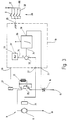
- Fig. 3 ein Schaltbild für das Antriebssystem nach Fig. 2,
- Fig. 4 ein Flußdiagramm für die Steuerung des Fahrwerks nach Fig. 2 und
- Fig. 5 Diagramme für den Stromflußwinkel und die Fahrgeschwindigkeit bei unterschiedlichen Betriebssituationen.
- 1 is a schematic diagram for a chassis with an asynchronous motor to largely suppress oscillations of the load,
- 2 shows a schematic diagram for a chassis with a motor with a main closing characteristic in order to suppress oscillations of the load,
- 3 shows a circuit diagram for the drive system according to FIG. 2,
- Fig. 4 is a flow chart for the control of the chassis according to Fig. 2 and
- Fig. 5 diagrams for the current flow angle and the driving speed in different operating situations.
Fig. 1 zeigt in einer Prinzipdarstellung eine mechanische Ausführungsform eines Antriebssystems für das Fahrwerk eines Hebezeugs, beispielsweise ein Katzfahrwerk, wie es bei flurfreien Fördereinrichtungen verwendet wird. Das Antriebssystem weist einen lediglich in einer Richtung laufenden Asynchronmotor 1 auf, dessen Ausgangswelle 2 mechanisch mit einem schematisch dargestellten Freilauf 3 gekuppelt ist. Ausgangsseitig ist der Freilauf 3 mit einer Eingangswelle 4 eines Untersetzungsgetriebes 5 verbunden, dessen Ausgangswelle 6 wiederum mit einem der Antriebsräder 7 drehfest gekuppelt ist. Das Antriebsrad 7 läuft auf einer schematisch gezeigten Fahrschiene 8.Fig. 1 shows a schematic representation of a mechanical embodiment of a drive system for the carriage of a hoist, for example a trolley, as used in floor-free conveyors. The drive system has an asynchronous motor 1 which only runs in one direction, the
Die Wirkungsweise der beschriebenen Antriebseinrichtung ist wie folgt:The operation of the drive device described is as follows:
Wenn über einen nicht gezeigten Steuerschalter dafür gesorgt wird, daß der Antriebsmotor 1 mit elektrischer Energie versorgt wird, beginnt er sich zu drehen und zwar mit der konstruktiv vorgegebenen Drehrichtung. Er treibt dabei über den in dieser Richtung kraftschlüssig kuppelnden Freilauf 3, die Eingangswelle 4 des Getriebes 5 an, das daraufhin das Antriebsrad 7 in Bewegung setzt. In Folge des relativ großen Anlaufsdrehmomentes des Asynchronmotors 1 wird das Fahrwerk relativ abrupt beschleunigt. Dieser starken Beschleunigung kann die an dem Lastaufnahmemittel in Gestalt eines Seils oder einer Kette hängenden Last nicht folgen, weshalb sie dem Fahrwerk zunächst nacheilen wird. Nach einer von den Verhältnissen abhängigen Zeit erreicht der Asynchronmotor 1 seine Nenndrehzahl, was bedeutet, daß das Fahrwerk von nun an mit konstanter Geschwindigkeit längs der Fahrschiene 8 fahren wird. Die zunächst der Bewegung des Fahrwerks nacheilende Last bildet unter der mit konstanter Geschwindigkeit fahrenden Fahrwerk ein Pendel, das durch die ruckartige Anfahrbewegung ausgelenkt wird und der mit der ihm eigenen Zeitkonstante schwingt, die von der ausgefahrenen Länge des Lastaufnahmemittels und der Masse der angehängten Last abhängig ist. Entsprechend dieser Zeitkonstante wird nach einer entsprechenden Fahrstrecke des Fahrwerks die in Fahrrichtung pendelnde Last das Fahrwerk einholen, in dem Sinne, daß sich die Last unmittelbar unter dem Fahrwerk befindet. Bis zu diesem Zeitpunkt hat die pendelnde Last eine verzögernde Kraft auf das Fahrwerk ausgeübt. Beginnend mit dem Augenblick, wo sich die Last unter dem Fahrwerk befindet und von nun an, da die Last im Sinne eines Vorauseilens das Fahrwerk überholt, wird die Last eine Zugkraft auf das Fahrwerk ausüben, die bestrebt ist, das Fahrwerk zu beschleunigen.If a control switch, not shown, is used to ensure that the drive motor 1 is supplied with electrical energy, it begins to rotate, specifically with the design direction of rotation. He drives the
Der Asychnronmotor 1 kann dieser Beschleunigung nicht folgen, weil er höchstens bis zur synchronen Drehzahl beschleunigen kann, die im praktischen Betrieb nur wenige Prozent unter der beim Antrieb des Fahrwerks auftretenden Lastdrehzahl liegt. Der Freilauf 7 kuppelt in dieser Betriebssituation aus und ermöglicht es so, dem Fahrwerk der nach vorne schwingenden Last zu folgen. Die nach vorne schwingende Last wird dabei einen Teil ihrer Pendelenergie als Vortriebsenergie in das Fahrwerk einspeisen. Die Folge ist, daß das von der Last gebildete Pendel im Umkehrpunkt nicht soweit von der Nullage, in der sich die Last unmittelbar unter dem Fahrwerk befinden würde, entfernt ist, wie dies der Fall wäre, wenn der Antriebsstrang zwischen dem Rad 7 und dem Motor 1 nicht ausgekuppelt hätte. In Folge des selbsttätigen Auskuppelns des Freilaufs 3 hat das von der Last nachgezogene Fahrwerk einen Teil der Pendelenergie aufgenommen.The asychnron motor 1 cannot follow this acceleration because it can accelerate at most up to the synchronous speed, which in practical operation is only a few percent below the load speed that occurs when driving the undercarriage. The
Dadurch kann in wenigen Pendelzyklen die gesamte Pendelenergie herausgedämpft werden, ohne steuerungstechnische Maßnahmen zu benötigen. Die Pendeldämpfung erfolgt dabei jeweils beim Vorwärtsschwung, d.h. derjenigen Hälfte der Schwingung, in der die Last bestrebt ist, dem Fahrwerk vorauszueilen, weil während dieser Halbwelle die Pendelenergie in Fahrenergie für das Fahrwerk umgesetzt wird. Der Motor 1 liefert während dieser Phase selbst keine Vortriebsenergie. Da das Pendel immer symmetrisch zur Nullage schwingen muß (es kann nicht ständig schräg im Raum stehen), ist die Amplitude im Rückschwung höchstens so groß wie die Amplitude beim zuletzt vorausgehenden Vorwärtsschwung.As a result, the entire pendulum energy can be damped out in a few pendulum cycles without the need for control measures. The pendulum damping takes place during the forward swing, ie the half of the oscillation in which the load strives to lead the undercarriage because during this half-wave the pendulum energy is converted into driving energy for the undercarriage. The motor 1 itself does not deliver any propulsion energy during this phase. Since the pendulum must always swing symmetrically to the zero position (it cannot always be at an angle in space), the amplitude in the backswing is at most as large as the amplitude in the last forward swing.
Ohne den im Antriebsstrang zwischen dem Motor 1 und dem Antriebsrad 7 befindlichen Freilauf 3 würde keine so wirksame Pendeldämpfung zustandekommen, denn dann wäre das Pendel gleichsam starr aufgehängt und könnte in seiner Aufhängung keine Energie übertragen. Anders dagegen bei der Verwendung des Freilaufes 3, wodurch eine Antriebsanordnung zustandekommt, die einem gedämpft aufgehängten Pendel entsprechen würde.Without the
Die in Figur 1 gezeigte rein mechanische Lösung eignet sich vorzugsweise für Einschienenhängebahnen, bei denen die Fahrwerke längs einer geschlossenen Bahn immer in derselben Richtung fahren. Wenn eine Drehrichtungsumkehr erforderlich ist, müßte der Freilauf 3 in seiner Wirkungsrichtung entsprechend der Fahrrichtung umgekehrt werden und zwar so, daß eine in Fahrrichtung auf das Fahrwerk einwirkende Kraft in der Lage sein muß, das Fahrwerk tatsächlich unter Abkuppelung von dem Motor 1 zu beschleunigen.The purely mechanical solution shown in FIG. 1 is preferably suitable for monorail overhead conveyors in which the trolleys always run in the same direction along a closed path. If a reversal of the direction of rotation is required, the
Fig. 2 zeigt eine Ausführungsform der neuen Antriebseinrichtung, bei der mechanische Freilauf 3 gleichsam elektrisch nachgebildet ist.2 shows an embodiment of the new drive device, in which
Der Antriebsmotor bei der Ausführungsform nach Fig. 2 ist ein im Hauptschlußbetrieb arbeitender Universalmotor 9 bestehend aus einem Anker 11 und einer zugehörigen Feldwicklung 12. Der Anker 11 liegt mit einer Anschlußklemme an einemr Phasenleiter 13 eines Wechselstromnetzes, während einer anderer Anschluß des Ankers 11 mit einem Ende der Feldwicklung 12 verbunden ist. Das andere Ende der Feldwicklung liegt über einen Triac 14 an einer anderen Phasenleiter 15 oder einem Nulleiter des Wechselstromnetzes. Der Anker 11 treibt eine Eingangswelle 16 eines Untersetzungsgetriebes 17, dessen Ausgangswelle 18 wiederum drehfest mit dem Antriebsrad 7 des Fahrwerkes verbunden ist.The drive motor in the embodiment according to FIG. 2 is a
Der Triac 14 wird mittels einer elektronischen Steuereinrichtung 19 gesteuert, deren Ausgang 21 Triggerimpulse an das Gate des Triac 14 liefert. Die Steuerung 19 weist einen Eingang 22 auf, der über eine Verbindungsleitung 23 mit einem Drehzahlgeber 24 verbunden ist. Der Drehzahlgeber 24 ist drehfest mit dem Anker 11 gekuppelt.The
Die Betätigung der Steuerung 19 geschieht durch eine an einem Eingang 25 angeschlossene schematisch angedeutete Schalteranordnung 26. Diese Schalteranordnung 26 kann wahlweise eine manuell zu betätigende Tastschalteranordnung sein oder sie können auch Signale repräsentieren, die von einer übergeordneten Steuerung kommen und die Steuerung 19 betätigen bzw steuern. Der Einfachheit halber sei angenommen, daß es sich um Handtaster handelt, die vom Benutzer des betreffenden Hebezeugs bedient werden.The
Nachstehend ist die Arbeitsweise der Anordnung nach Fig. 2 erläutert und zwar unter der Annahme, daß die Schalteranordnung 26 lediglich zwei Schaltstellungen kennt, nämlich eine Neutral- oder Nullstellung und eine Fahrstellung.The operation of the arrangement according to FIG. 2 is explained below, namely on the assumption that the
In der Neutral- oder Nullstellung gibt die Steuerung 19 keine Triggerimpulse an den Triac 14 ab, weshalb der durch den Motor 9 führende Stromkreis unterbrochen bleibt.In the neutral or zero position, the
Will der Benutzer das Fahrwerk des Hebezeugs in Gang setzen, betätigt er den Tastschalter 26, d.h. er bringt den Schalter in die Fahrstellung. Die Steuerung 19 bekommt dadurch an ihrem Eingang 25 ein entsprechendes Signal und beginnt von da an mit der Wechselspannung des Netzes synchronisierte Triggerimpulse in bekannter Weise an das Gate des Triac 14 zu liefern. Bei jedem ersten Zündimpuls für den Triac 14 geht dieser in den leitenden Zustand und bleibt leitend, solange bis die Netzwechselspannung und damit verbunden auch der Strom durch den Universalmotor 9 verschwindet. Der Triac 14 löscht zu diesem Zeitpunkt und bleibt während der nächsten Halbwelle solange gesperrt, bis er an seinem Gate einen erneuten Zündimpuls seitens der Steuerung 19 bekommt.If the user wants to start the gear of the hoist, he actuates the
Die relative Lage der Zündimpulse gegenüber den jeweils vorausgehenden Nullstellen der Netzwechselspannung, auch Phasenanschnitt- oder Zündwinkel genannt, bestimmt welche Leistung der Universalmotor 9 dem Netz entnehmen kann. Die Steuerung 19 wirkt als Regler und regelt den Phasenanschnitt- oder Zündwinkel im Sinne einer Stabilisierung der Drehzahl des Universalmotors 9, wozu sie über den Drehzahlsensor 24 dessen Ankerdrehzahl erfaßt. Die Steuerung 19 ist somit im weitesten Sinne ein Regler, der bei entsprechendem Signal an seinem Eingang 25 die dem Universalmotor 9 zugeführte elektrische Leistung so einstellt, daß der Universalmotor 9 mit einer vorgegebenen Drehzahl läuft.The relative position of the ignition pulses in relation to the preceding zeros of the AC mains voltage, also called phase angle or ignition angle, determines what power the
Wegen dieses Verhaltens der Steuerung 19 wird der Phasenanschnittwinkel für den Universalmotor 9 klein und folglich der Stromflußwinkel groß, wenn der Motor belastet wird und seine Drehzahl zu sinken droht bzw. umgekehrt wird der Phasenanschnittwinkel groß und damit der Stromflußwinkel klein, wenn die Drehzahl des Universalmotors 9 wegen einer Beschleunigung oder Entlastung steigen will.Because of this behavior of the
Der angenommene Benutzer hat bei stillstehendem Fahrwerk den Tastschalter 26 in die Fahrstellung gebracht. Da die Steuerung 19 von dem Sensor 24 die Drehzahl Null gemeldet bekommt, wird sie den Triac 14 zunächst einmal mit einem sehr kleinen Phasenanschnittwinkel betreiben, damit der Universalmotor 9 viel elektrische Leistung dem Netz entnehmen kann, um das Fahrwerk zu beschleunigen. In dem Maße, in dem sich seine Drehzahl der Solldrehzahl nähert, beginnt die Steuerung 19 den Phasenanschnittswinkel zu vergrößern, was zu einer Verminderung der Leistungsaufnahme aus dem Netz erfolgt, solange bis die Nenndrehzahl erreicht ist.The assumed user has brought the
Wie bereits oben beschrieben, wird wegen des Anfahrvorgangs die Last dem Fahrwerk nacheilen, d.h. das von der Last gebildete Pendel ist entgegen der Fahrtrichtung ausgelenkt. Sobald der Universalmotor 9 seine Nenndrehzahl erreicht hat, die mit Hilfe der Steuerung 19 eingeregelt wird, hört die weitere Beschleunigung der pendelnden Last auf. Die Pendelschwingung wird nun in Richtung der Fahrtrichtung erfolgen. Sobald dabei das von der Last gebildete Pendel seine Nullage, bei der sich die Last unmittelbar vertikal unter dem Fahrwerk befindet oder mit anderen Worten das Lastaufnahmemittel parallel zum Schwerkraftvektor ausgerichtet ist, überschritten hat und beginnt nach vorne in Fahrtrichtung dem Fahrwerk vorauszueilen, ist die Last bestrebt, das Fahrwerk hinter sich herzuziehen. Die elektrischen Eigenschaften des im Hauptschlußbetrieb arbeitenden Universalmotors 9 in Verbindung mit der Steuerung 19 wirken jetzt wie bei dem Ausführungsbeispiel nach Fig. 1 der Freilauf 3, indem sie es dem Fahrwerk ermöglichen, durch die Last angetrieben zu werden. Die voreilende Last will das Fahrwerk ziehen und führt so zu einer abtriebsseitigen Entlastung des Motors 9, der folglich weniger Antriebsenergie liefern muß.As already described above, the load will lag the chassis due to the start-up process, i.e. the pendulum formed by the load is deflected against the direction of travel. As soon as the
Dieses Weniger an Antriebsenergie würde ohne Eingreifen der Steuerung 19 nicht wirksam werden, sondern der Universalmotor 9 würde bei Entlastung seine Drehzahl weiter erhöhen, wenn die Leistung zuvor aus dem Stromnetz konstant bleibt. Die Regelung durch die Steuerung 19 wirkt dem jedoch entgegen, in dem Sinne, daß sie den Phasenanschnittwinkel vergrößert, um eine solche Beschleunigung des Fahrwerks, die durch Zusammenwirken der nach vorne schwingenden Last und dem Antriebsmotor zustandekommen würde, zu verhindern. Da jetzt der Universalmotor 9 weniger Antriebsleistung bereitstellt, muß die zum Fahren notwendige Energie aus der Pendelenergie gespeist werden und außerdem läuft das Fahrwerk der Last nach, was bedeutet, daß das Pendel während der Phase des Vorwärtsschwungs gedämpft wird.This less drive energy would not be effective without the intervention of the
Wesentlich unterstützend wirkt dabei die Hauptschlußcharakteristik des Universalmotors 9, der eine hyperbolisch verlaufende Drehzahl-Drehmoment-Kennlinie aufweist und bei dem es keine Grenzdrehzahl gibt, oberhalb der er als Generator und somit bremsend für das Fahrwerk wirken könnte. Jede Stabilisierung der Fahrgeschwindigkeit im Sinne eines Festklemmens der Fahrgeschwindigkeit würde die Pendeldämpfung verhindern. Da aber der Hauptschlußmotor nicht als eine solche Bremse wirken kann, ist die nach vorne in Fahrtrichtung schwingende, das Fahrwerk überholende Last in der Lage, das Fahrwerk hinter sich herzuschleppen, wodurch die nach vorne gerichtete Amplitude vermindert wird. Unter nach vorne gerichteter Amplitude ist dabei die im Umkehrpunkt auftretende Maximalauslenkung gegenüber der Nullage zu verstehen. In der Nullage befindet sich die Last unmittelbar unter dem Fahrwerk und das Lastaufnahmemittel, also das Seil oder die Kette, verläuft parallel zum Schwerkraftvektor.The main closing characteristic of the
Ein wesentlicher Vorteil der Anordnung nach Fig. 2 besteht darin, daß kein mechanischer Freilauf benötigt wird, sondern daß verhältnismäßig billige und wenig Platz erfordernde elektronische Bauteile verwendet werden, um die Freilaufcharakteristik nachzubilden. Die Fahrstrecken, die ein Katzfahrwerk während der Lebensdauer zurücklegen muß, sind nicht so groß, als daß der bei einem Universalmotor vorhandene Kommutator und dessen Lebensdauer eine Beeinträchtigung darstellen würde.A major advantage of the arrangement according to FIG. 2 is that no mechanical freewheel is required, but that relatively cheap and space-saving electronic components are used to emulate the freewheeling characteristic. The distances that a trolley must travel during its life are not so large that the commutator present in a universal motor and its life would be an impairment.
Ferner kann durch Hinzunahme eines weiteren Schaltersatzes jederzeit die Drehrichtung des Universalmotors geändert werden, womit Fahrten in beiden Richtungen möglich sind. Es genügt hierzu, wenn die Feldwicklung 12 wie in Fig. 3 gezeigt in bekannter Weise über eine Polwendeeinrichtung mit dem Anker 11 elektrisch verbunden wird, um die Drehrichtung des Universalmotors 9 zu ändern. Das Fahrwerk kann mit Hilfe einer solchen Ergänzung wahlweise in beide Richtungen in Gang gesetzt werden, wobei in beiden Richtungen die pendeldämpfenden Eigenschaften des neuen Antriebskonzeptes wirksam werden.Furthermore, by adding another switch set, the direction of rotation of the universal motor can be changed at any time, which makes journeys in both directions possible. For this purpose, it is sufficient if the field winding 12 is electrically connected to the
Schließlich besteht ein wesentlicher Vorteil der Anordnung nach Fig. 2 darin, daß auf vergleichsweise einfacher Weise Fahrwerke mit mehreren Geschwindigkeiten oder auch stufenloser Geschwindigkeitseinstellung realisiert werden können, wie dies nachstehend erläutert ist.Finally, an essential advantage of the arrangement according to FIG. 2 is that undercarriages with several speeds or also stepless speed setting can be realized in a comparatively simple manner, as will be explained below.
Hierzu sei angenommen, daß die Steuerung 19 ein Mikroprozessor ist, der in der Lage ist, die gewünschten netzsynchronen Zündimpulse an seinem Ausgang 21 an den Triac 14 zu liefern, und der außerdem über seinen Eingang 25 an einen Schaltersatz angeschlossen ist. Dieser Schaltersatz hat, wie vorher eine Neutral- oder Nullstellung, eine erste Schaltstellung, die einer Schleichgeschwindigkeit entspricht, und eine zweite Schaltstellung, die der Eilgeschwindigkeit entspricht, wobei bei beiden Schalterstellungen das Fahrwerk in derselben Richtung läuft. Darüberhinaus gibt es eine dritte und eine vierte Schalterstellung, die dazu dienen, das Fahrwerk in der umgekehrten Richtung mit der Normal- oder der Eilgeschwindigkeit zu bewegen.For this purpose it is assumed that the
Fig. 3 zeigt das zugehörige Prinzipschaltbild und zwar ist dabei den Schalterstellung I bis IV jeweils ein eigener Schaltersatz zugeordnet, während die Null- oder Neutralstellung einer Betriebssituation entspricht, in der sämtliche Schalter gleichzeitig geöffnet sind.FIG. 3 shows the associated basic circuit diagram, namely that switch positions I to IV are each assigned a separate switch set, while the zero or neutral position corresponds to an operating situation in which all switches are open at the same time.
Soweit bei der Schaltungsanordnung nach Fig. 3 bereits beschriebene Bauteile wiederkehren, sind sie mit denselben Bezugszeichen versehen und nicht erneut beschrieben.To the extent that components already described in the circuit arrangement according to FIG. 3 recur, they are provided with the same reference symbols and are not described again.
Bei Anordnung nach Fig. 3 liegt die Feldwicklung 12 über einen von einer Relaiswicklung 27 betätigten Umpolschalter 28 in dem Serienstromkreis bestehend aus dem Anker 11 und dem Triac 14. Die Steuerung 19 ist im wesentlichen ein Mikroprozessor, der gegebenfalls um die erforderlichen Leistungsendstufen erweitert ist, die der Einfachheit halber nicht mitgezeichnet sind, da sie für das Verständnis der Erfindung nicht von Bedeutung sind.In the arrangement according to FIG. 3, the field winding 12 is located in the series circuit consisting of the
An den Eingang 25, der vier einzelne voneinander getrennte Leitungen aufweist, sind die den einzelnen Schaltzuständen entsprechenden Schalter, die mit I bis IV bezeichnet sind, angeschlossen. Sie sollen die unterschiedlichen Signalzustände am Eingang repräsentieren, wobei die oben genannte Zuordnung gilt. Diese Schalter I bis IV liegen an einem Ende gemeinsam an einer positiven Versorgungsgleichspannung U.The switches corresponding to the individual switching states, which are designated I to IV, are connected to the input 25, which has four individual lines which are separate from one another. They should represent the different signal states at the input, whereby the above assignment applies. These switches I to IV are connected at one end to a positive DC supply voltage U.
Zusätzlich zu dem Ausführungsbeispiel nach Fig. 2 hat die Steuerung 19 einen weiteren Ausgang 29, über den die Relaiswicklung 27 angesteuert wird, damit die Drehrichtung des Universalmotors 9 geändert werden kann.In addition to the exemplary embodiment according to FIG. 2, the
Mit Hilfe des die Steuerung 19 realisierenden Mikroprozessors wird ein PI-Regler 31, ein Soll-Istwert-Vergleicher 32 und eine umschaltbare Referenz 33 implementiert.With the help of the microprocessor implementing the
Ein Eingang des Soll-Istwert-Vergleichers 32 ist mit dem Eingang 22 verbunden, während der andere Eingang an einen Ausgang 34 der Referenz angeschlossen ist. Das von dem Vergleicher 32 erhaltene Ausgangssignal gelangt in einen Eingang 35 des PI-Reglers 31, der an einem Eingang 36 ebenso wie die Referenz an ihrem Eingang 37 über von dem Eingang 25 kommende Signale gesteuert wird.One input of the target /
Der PI-Regler 31 weist schließlich noch einen Ausgang 38 auf, der mit dem Ausgang 21 der Steuerung 19 in Verbindung steht.The PI controller 31 finally has an
Die Funktionen der Referenz 33 des Vergleichers 32 und des PI-Reglers 31 werden durch Programmabschnitte in dem Mikroprozessor verwirklicht. Fig. 5 zeigt das Flußdiagramm, das jenen Ausschnitt aus dem Gesamtprogramm des Mikroprozessors veranschaulicht, das für die gewünschte Steuerung des Motors 9 implimentiert ist. Mit Hilfe dieses Programms gemäß dem Flußdiagramm nach Fig. 4 arbeitet die Einrichtung wie folgt:The functions of the
Solange keiner der Schalter I bis IV betätigt ist, wird das in Fig. 4 gezeigte Flußdiagramm nicht durchlaufen. Erst die Betätigung eines der Schalter I bis IV bzw. das Zuführen eines entsprechenden Steuersignals führt dazu, daß der Mikroprozessor ein dem Flußdiagramm nach Fig. 4 entsprechendes Programm startet. Das Programm wird bei 41 begonnen und fragt an einer Programmstelle 42 ab, welcher der Schalter I bis IV betätigt ist. Dieser Betätigungszustand wird gespeichert und das Programm fährt dann fort, um bei 43 den Eingang 22 abzufragen, an dem ein die Drehzahl des Universalmotors 9 kennzeichnendes Signal von dem Drehzahlgeber 24 abgeliefert wird. Die Istdrehzahl vist wird abgespeichert und das Programm läuft zu der Programmstelle 44 weiter, an der eine Referenzdrehzahl generiert wird, mit der die Istdrehzahl verglichen wird.As long as none of the switches I to IV is actuated, the flow chart shown in FIG. 4 is not followed. It is only when one of the switches I to IV is actuated or a corresponding control signal is supplied that the microprocessor starts a program corresponding to the flow chart in FIG. 4. The program begins at 41 and asks at a
Parameter für diesen Rampengenerator zur Führung der Istdrehzahl ist der betätigte Schalter und die Zeit, die seit der Betätigung des Schalters vergangen ist. Für die weitere Beschreibung sei angenommen, daß dem Schalter I eine Normalgeschwindigkeit in Vorwärtsrichtung, dem Schalter II eine Eilgeschwindigkeit in Vorwärtsrichtung, dem Schalter III eine Normalgeschwindigkeit in Rückwärtsrichtung und dem Schalter IV die Eilgeschwindigkeit in Rückwärtsrichtung zugeordnet sind.The parameters for this ramp generator for guiding the actual speed are the operated switch and the time that has elapsed since the switch was operated. For the further description it is assumed that the switch I a normal speed in the forward direction, the switch II a rapid speed in the forward direction, the Switch III a normal speed in the reverse direction and the switch IV the rapid speed in the reverse direction are assigned.
Je nachdem, welcher dieser Schalter betätigt wurde, läuft der Rampengenerator während mehrerer Programmdurchläufe allmählich entweder bis zu einer der Normalgeschwindigkeit entsprechenden Geschwindigkeit oder bis zu einer der Eilgeschwindigkeit entsprechenden Geschwindigkeit hoch.Depending on which of these switches has been operated, the ramp generator gradually runs up to a speed corresponding to normal speed or to a speed corresponding to rapid speed during several program runs.
Nach der Definition bzw. Aktualisierung der Führungsgröße Vsoll wird an der Verzweigungsstelle 45 abgefragt, ob seit dem letzten Durchlauf an dieser Stelle sich der Zustand an dem Eingang 25 geändert hat bzw. ob die Schalterstellung verändert wurde oder ob nach einer vorausgehenden Schalteränderung erstmalig der Referenzwert Vsoll überschritten wurde.After the definition or update of the command variable V should , a query is made at the branching
Für die weitere Erläuterung sei angenommen, daß erstmalig der Schalter I betätigt wurde, was einem Anfahren aus dem Stillstand und einer Beschleunigung bis zu der Normalgeschwindigkeit entspricht. Das Programm geht deswegen zu der Verzweigungsstelle 46, an der geprüft wird, ob aus dem Zustand keine Schalterbetätigung in den Zustand mit der Schalterbetätigung des Schalters I oder des Schalters II gewechselt wurde. Für die Rückwärtsrichtung gelten natürlich sinngemäß an der Stelle die Werte III und IV. Wenn diese Prüfung positiv ausfällt, also ein Zustandswechsel stattgefunden hat, der einer Beschleunigung aus dem Stillstand entspricht, geht das Programm zu einem Anweisungsblock 47, an dem ein integraler Anteil φ für den Stromflußwinkel auf einen vorgegebenen Startwert φs1 gesetzt wird. Damit wird für die Anfahrphase aus dem Stillstand ein fester Stromflußwinkel eingestellt, der einem weitgehend ruckfreien, aber hinreichend schnellen Anfahren aus dem Stand entspricht.For the further explanation it is assumed that the switch I was actuated for the first time, which corresponds to a start from standstill and an acceleration up to normal speed. The program therefore goes to the branching
Sodann fährt das Programm an einem Anweisungsblock 48 fort. Bei 48 berechnet das Programm die Differenz zwischen dem Referenzwert vsoll und der Istgeschwindigkeit vist und gewinnt hieraus einen Regelabweichungsparameter p.The program then continues at an
Auf diese Berechnung erfolgt bei 49 eine Verzweigung, abhängig davon, ob der Regelabweichungsparameter p größer als null ist oder nicht. Wenn der Regelabweichungsparameter p größer als null ist, bedeutet dies, daß die Istdrehzahl nach wie vor kleiner als die Solldrehzahl ist oder die dem Universalmotor 9 zugeführte elektrische Leistung reicht noch nicht aus, um den Fahrantrieb auf die gewünschte Geschwindigkeit zu bringen. Deshalb wird in einem Anweisungsblock 51 der Stromflußwinkel φ um ein Δ vergrößert und erneut abgespeichert. Dabei kann der Inkrementalwert Δ selbst seine Funktion des Regelabweichungsparameters p oder aber konstant sein.This calculation branches at 49, depending on whether the system deviation parameter p is greater than zero or not. If the control deviation parameter p is greater than zero, this means that the actual speed is still lower than the target speed or the electrical power supplied to the
Da der Regler 31 als PI-Regler wirkt, muß zu dem Stromflußwinkel φ, der den Integralanteil repräsentiert, noch ein Proportionalanteil hinzuaddiert werden. Hieraus wird der tatsächliche Stromflußwinkel α erhalten, indem zu dem Integralanteil φ des Stromflußwinkels der Regelabweichungsparameter p bzw. eine davon abgeleitete Größe hinzuaddiert wird.Since the controller 31 acts as a PI controller, a proportional component must also be added to the current flow angle φ, which represents the integral component. The actual current flow angle α is obtained from this by adding the control deviation parameter p or a variable derived from it to the integral component φ of the current flow angle.
Nachdem so der Stromflußwinkel α bestehend aus dem integralen und dem propotionalen Anteil berechnet wurde, wird bei 52 der Stromflußwinkel α in den Zeitpunkt umgerechnet, an dem, bezogen auf die vorausgehende Nullstelle der Netzwechselspannung, der Zündimpuls für den Triac 14 abgegeben werden muß, um den gewünschten Stromflußwinkel zu bekommen. Das Programm kehrt daraufhin zu dem Block 42 zurück und überprüft, ob sich in der Zwischenzeit die Stellung der Schalter I bis IV verändert hat. Angenommen, es wurde keine Änderung beobachtet, dann bleibt der gespeicherte Zustand über die Schalterbetätigung erhalten und das Programm kann bei 43 erneut die Istdrehzahl vist abfragen und die entsprechende Speichervariable aktualisieren.After the current flow angle α consisting of the integral and the proportional portion has been calculated in this way, the current flow angle α is converted at 52 into the point in time at which, based on the preceding zero of the mains AC voltage, the ignition pulse for the
Da, wie erwähnt, der Parameter für die Sollgeschwindigkeit vsoll zeitlich vergrößert wird, bis auf den Wert, der der betreffenden Schalterbetätigung I oder II bzw. III oder IV entspricht, steigt der Wert der Führungsgröße vsoll allmählich während aufeinanderfolgender Durchläufe an.Since, as mentioned, the parameter for the desired speed v soll is increased in time up to the value that corresponds to the switch actuation I or II or III or IV in question, the value of the command variable v soll increases gradually during successive runs.
Wie eingangs vorausgesetzt, war die Schalterbetätigung nicht verändert worden und außerdem befindet sich das Fahrwerk nach wie vor in der Beschleunigungsphase, d.h. vist ist kleiner als die durch die Schalterbetätigung vorgegebene Zielgeschwindigkeit. Das Programm wird deswegen unmittelbar über den Block 48 fortfahren und im Block 51 den integralen Anteil φ des Stromwinkels inkremental erhöhen, während andererseits der Regelabweichungsparameter p allmählich kleiner wird, weil die Differenz zwischen Vist und vsoll sich entsprechend vermindert.As provided above, the switch operation had not been changed and also there is the landing gear is still in the acceleration phase, ie v is smaller than the predetermined switch operation by the target speed. The program will therefore continue directly through the
Nachdem eine Vielzahl von Durchläufen in der beschriebenen Art erfolgt ist, wird irgendwann der Zeitpunkt eintreten, an dem der Rampengeneratur einen Referenzwert vsoll zur Verfügung stellt, der gleich der Zielgeschwindigkeit ist, mit der das Fahrwerk entsprechend der Schalterbetätigung I fahren soll. Von da an liefert der Rampengenerator bei 44 einen konstanten Referenzwert vsoll solange, bis sich die Schalterstellungen am Eingang 25 verändern.After a large number of runs have been carried out in the manner described, the point in time will come at which the ramp generation will provide a reference value v soll which is equal to the target speed at which the undercarriage is to travel in accordance with switch actuation I. From then on, the ramp generator at 44 provides a constant reference value v soll long change until the switch positions at the entrance 25th
Während der Beschleunigungsphase wird ebenfalls nach mehreren Durchläufen der oben beschriebenen Programmschleife erstmalig die Situation auftreten, daß die Istgeschwindigkeit vist die Referenzgeschwindigkeit vsoll überschreitet. In der Regel ist zu diesem Zeitpunkt wegen der vorausgehenden Beschleunigungsphase der Stromflußwinkel α größer als es für das Fahren mit der konstanten Geschwindigkeit vsoll erforderlich ist, obwohl inzwischen der Proportionalanteil p nahezu zu null geworden ist. Diese Reglersituation mit einem zu großen integralen Anteil φ würde zu einem unerwünschten Überschießen bei der Fahrgeschwindigkeit führen, weshalb das Programm bei 45 nicht unmittelbar in den Block 48 geht, sondern nach dem Vergleich des Sollwertes mit dem Istwert in dem linken Teil bei 53 fortfährt, wo eine Verzweigung zu einem Anweisungsblock 54 vorgesehen ist. In dem Anweisungsblock 54 wird der integrale Anteil des Stromflußwinkels φ sprunghaft um einen größeren Betrag als Δ vermindert, indem von dem integralen Anteil des Stromflußwinkels φ eine feste Größe K1 abgezogen wird. Nach dieser Rechenoperation fährt das Programm, wie beschrieben, bei 48 fort.During the acceleration phase, the situation is the reference speed v soll is also after several iterations of the program loop described above occur the first time that the actual speed v exceeds. In general, the current flow angle α is greater than it is v for driving with constant speed is required at this time because of the previous acceleration phase, although now the proportional component P is almost become zero. These Controller situation with too large an integral part φ would lead to an undesirable overshoot in the driving speed, which is why the program does not go directly to block 48 at 45, but continues after comparing the desired value with the actual value in the left part at 53, where one Branch to an
Wenn beim nächsten Schleifendurchlauf die Istgeschwindigkeit immer noch größer als die Sollgeschwindigkeit ist, wird nunmehr an der Verzweigungsstelle 45 wiederum wie ursprünglich bei 48 fortgefahren, denn es handelt sich nicht um das erste Überschreiten des Referenzwertes vsoll nach einer vorausgehenden Änderung der Schalterstellungen. Da in dieser Betriebssituation die Istgeschwindigkeit immer noch größer ist als die Sollgeschwindigkeit wird der Regelabweichungsparameter negativ sein, weshalb das Programm nach der Verzweigungsstelle 49 nicht zu dem Anweisungsblock 51 geht, sondern zu einem Anweisungsblock 55. In diesem Anweisungsblock 55 wird der Integralanteil des Stromflußwinkels φ inkremental um Δ vermindert, das wiederum eine Funktion von p sein kann oder einen konstanten Wert aufweist. In der nächsten Zeile wird der integrale Anteil φ um den Betrag des Regelabweichugsparameters p oder einer daraus abgeleiteten Größe vermindert, um den wirklichen Stromflußwinkel α zu erhalten, der dann wiederum an der Programmstelle 52 in den entsprehend abgebegenen Zündimpuls umgesetzt wird.If the next time through the loop, the actual speed is still higher than the target rate is now at the
In der stationären Phase wird nach wie vor fortlaufend das in Fig. 4 skizzenhaft beschriebene Programm durchlaufen, wobei die Fahrgeschwindigkeit ständig um die Sollgeschwindigkeit herumpendeln wird, weshalb das Programm nach der Verzweigungsstelle 49 abwechselnd über den Anweisungsblock 51 oder den Anweisungsblock 55 fortfahren wird.In the stationary phase, the program outlined in FIG. 4 continues to be run continuously, the driving speed constantly oscillating around the desired speed, which is why the program after
Die eingangs erwähnte Freilaufcharakteristik wird dadurch realisiert, daß während des Vorpendelns der Last und damit während der Schleppens des Fahrwerks durch die pendelnde Last die Sollgeschwindigkeit überschritten wird, was dazu führt, daß der PI-Regler über den Anweisungsblock 55 läuft und zunehmend den Integralanteil φ verkleinert. Der Stromflußwinkel wird entsprechend kleiner, d.h. die Vortriebsenergie für das Fahrwerk kommt aus der ziehenden Last.The free-wheeling characteristic mentioned at the outset is realized by the fact that the set speed is exceeded during the swinging of the load and thus during the towing of the chassis by the swinging load, which leads to the PI controller running via the
Zum Stillsetzen des Fahrwerks läßt der Benutzer sämtliche Schalter los, womit der Durchlauf des Programms nach Fig. 4 beendet wird.To stop the undercarriage, the user releases all switches, which ends the run of the program according to FIG. 4.
Zusätzlich zu den beschriebenen Funktionen müssen noch eine Reihe anderer Varianten berücksichtigt werden. Eine Variante ist die Betätigung des Schalters II, d.h. dem Anfahren und anschließenden Beschleunigen bis zu der Eilgeschwindigkeit. Diese Maßnahme macht sich im wesentlichen nur im Bereich des Sollwertgebers bei 44 bemerkbar, insofern, als dort der Referenzparameter Vsoll bis zu der der Eilgeschwindigkeit entsprechenden Zielgeschwindigkeit hochgesetzt wird. Ansonsten verhält sich das Programm wie vorher beschrieben, denn es läuft beim ersten Start, ausgehend vom Zustand null, wie vorher über die Verzweigungsstelle 46 und den Anweisungsblock 47.In addition to the functions described, a number of other variants must also be taken into account. A variant is the actuation of switch II, ie starting and then accelerating up to the rapid speed. This measure is essentially only noticeable in the area of the setpoint generator at 44, insofar as the reference parameter V soll is increased there up to the target speed corresponding to the rapid speed. Otherwise, the program behaves as previously described, because it starts at the first start, starting from state zero, as before via
Die nächste Variante, die zu berücksichtigen ist, besteht in der Betätigung des Schalters II, nachdem bereits der Schalter I betätigt worden ist und das Fahrwerk mit der Normalgeschwindigkeit fährt. Dies entspricht einem Beschleunigen aus der Normalgeschwindigkeit in die Eilgeschwindigkeit.The next variant that has to be taken into account is the actuation of switch II after switch I has already been actuated and the undercarriage is traveling at normal speed. This corresponds to an acceleration from normal speed to rapid speed.
Um hier die unangenehmen langsamen Regelcharakteristiken des Integralreglers zu vermeiden, läuft beim ersten Durchlauf nach der Betätigung des Schalters II das Programm im Anschluß an die Verzweigung 45 zu einer Verzweigungsstelle 56, an die sich ein Anweisungsblock 57 anschließt, wo der Integralanteil φ sprunghaft um eine Konstante K2 vergrößert wird. Im Anschluß daran verhält sich das Programm wie eingangs beschrieben.In order to avoid the uncomfortable slow control characteristics of the integral controller, the program runs at the first run after actuation of switch II following
Die letzte Variante, die zu beachten ist, besteht im Zurückschalten von der Schalterstellung II in die Schalterstellung I, also einem Verlangsamen der Fahrgeschwindigkeit aus der Eilgeschwindigkeit in die Normalgeschwindigkeit. Beim ersten Schleifendurchlauf nach einem solchen Zustandswechsel geht das Programm an der Verzweigungsstelle 45 in den linken Ast nach Fig. 4 zu einer Verzweigungsstelle 58, in der überprüft wird, ob die Istgeschwindigkeit größer ist als die Sollgeschwindigkeit, was in der Regel beim Zurückschalten immer der Fall sein wird, woraufhin dann über einen Anweisungsblock 59 in den Normalteil des Programms zu dem Anweisungsblock 48 zurückgekehrt wird. In dem Anweisungsblock 59 wird der Integralanteil φ auf einen neuen Anfangswert φS2 gesetzt, der kleiner ist als es dem Fahren mit der Normalgeschwindigkeit entspricht.The last variant to be observed consists in switching back from switch position II to switch position I, i.e. slowing the driving speed from the rapid speed to the normal speed. During the first loop run after such a change of state, the program goes at branching
Wie die Schalterstellungen III und IV in den Rückwärtsbetrieb umzusetzen sind, ist dem Fachmann bekannt und braucht deswegen nicht näher beschrieben zu werden. Das Regelprogramm hingegen ist dasselbe, wie es im Zusammenhang mit den Schalterstellungen I und II erläutert wurde.How the switch positions III and IV are to be implemented in reverse operation is known to the person skilled in the art and therefore need not be described in more detail. The control program, however, is the same as that explained in connection with switch positions I and II.
Abgesehen von einer stufenweisen Umschaltung der Fahrgeschwindigkeit ist es auch möglich, die Fahrgeschwindigkeit stufenlos zu variieren. In diesem Falle wird ein Programm entsprechend dem Flußdiagramm nach Fig. 5 verwendet. Soweit hier bereits erläuterte Verzweigungsstellen und Anweisungsblöcke auftreten, sind sie mit denselben Bezugszeichen wie bei dem Flußdiagramm nach Fig. 4 versehen und nicht erneut beschrieben.Apart from a gradual change in the driving speed, it is also possible to vary the driving speed continuously. In this case, a program according to the flow chart of Fig. 5 is used. If branch points and instruction blocks already explained occur here, they are the same Reference numerals as in the flow chart of Fig. 4 provided and not described again.
Der wesentliche Unterschied besteht darin, daß die Schalterstellung I bzw. die Schalterstellung III einem Zustand entspricht, in dem das Fahrwerk mit der zum Umschaltzeitpunkt erreichten Fahrgeschwindigkeit weiterfahren soll. Die Schalterstellung II und dementsprechend auch die Schalterstellung IV hingegen bedeutet Anfahren oder Beschleunigen des Fahrzeugs, solange wie dieser Schalterzustand beibehalten wird oder eine maximal zulässige Fahrgeschwindigkeit noch nicht überschritten ist.The main difference is that switch position I or switch position III corresponds to a state in which the undercarriage should continue to travel at the travel speed reached at the switchover time. Switch position II and, accordingly, switch position IV, on the other hand, mean starting or accelerating the vehicle as long as this switch state is maintained or a maximum permissible driving speed has not yet been exceeded.
Unter Berücksichtigung dieser geänderten Bedeutungen der Schalterstellungen I bis IV arbeitet das Programm wie folgt:Taking these changed meanings of switch positions I to IV into account, the program works as follows:
Zum Anfahren aus dem Stillstand muß der Benutzer die Schalterstellung II oder IV erreichen, was bedeutet, daß in dem Rampengenerator der Referenzwert Vsoll im Verlauf mehrerer Schleifendurchläufe bis maximal auf den Wert Vmax gesetzt wird. Dieses Verhalten an dem Block 44 entspricht insoweit etwa dem Verhalten des Blocks 44 nach Fig. 4.To start from standstill, the user must reach switch position II or IV, which means that in the ramp generator the reference value V soll is set to a maximum of V max in the course of several loop runs. To this extent, this behavior at
Da aus dem Stillstand angefahren wurde, also der Schalter II erstmals betätigt worden ist, verzweigt das Programm an der Abfragestelle 45 in den linken Teil zu einer Abfragestelle 61, die im wesentlichen mit der Abfragestelle 46 nach Fig. 4 korrespondiert. Wenn die dort das Kriterium bildende Bedingung erfüllt ist, wird der Integralanteil φ des Stromflußwinkels auf einen Startwert φs1 gesetzt und das Programm fährt bei dem Anweisungsblock 48 weiter, von wo ab es sich genauso verhält, wie dies im Zusammenhang mit Fig. 4 erläutert ist.Since the vehicle was started from a standstill, that is, switch II was actuated for the first time, the program branches at
Angenommen während der Beschleunigungsphase stellt der Benutzer fest, daß das Fahrwerk sich jetzt mit der gewünschten Geschwindigkeit bewegt, dann wird er in den Zustand I umschalten. Dies hat zur Folge, daß bei dem Rampengenerator 44 eine Verzweigung bei 62 so durchlaufen wird, daß als Referenzwert Vsoll der gemessene aktuelle Wert Vist übernommen wird. Mit anderen Worten, die zum Umschaltzeitpunkt erreichte aktuelle Fahrgeschwindigkeikt wird der Bezugswert, um den herum künftig die Fahrgeschwindigkeit eingeregelt werden soll. Diese Aktualisierung oder Übernahme geschieht allerdings nur dann, wenn das Programm das Umschalten aus dem Zustand II in den Zustand I erkennt, nicht jedoch, wenn der Zustand I dauernd anhält.Assuming during the acceleration phase that the user determines that the undercarriage is now moving at the desired speed, then he will be in the Switch over state I. The result of this is that the
An der Verzweigungsstelle 45 wird ebenfalls nochmals die Umschaltung aus dem Zustand II in den Zustand I erkannt, womit das Programm wiederum in den linken Ast verzweigt und zu der Abfragestelle 63 läuft. Hier veranlaßt das Programm, daß der integrale Anteil φ sprunghaft um eine Konstane K2 vermindert wird, weil während der vorausgehenden Beschleunigungsphase der Stromflußwinkel Werte erreicht hat, die größer sind, als sie zum Fahren mit der konstanten Geschwindigkeit erforderlich sind. Die sprunghafte Änderung des Integralanteils φ vermeidet ein unnötiges Überschießen der Fahrgeschwindigkeit, wenn von dem Zustand II (= Beschleunigen) in den Zustand I (= Geschwindigkeit halten) zurückgeschaltet wird. Der Regler schwingt dadurch schneller ein.The changeover from state II to state I is again recognized at branching
Nach der sprunghaften Änderung des Integralanteils φ in dem Block 64 kehrt das Programm zu dem Anweisungsblock 48 zurück und verhält sich ansonsten wie im Zusammenhang mit Fig. 4 ausführlich beschrieben.After the sudden change in the integral component φ in
Wenn aus der gehaltenen Geschwindigkeit heraus weiter beschleunigt werden soll, hat dies lediglich Auswirkungen auf das Verhalten des Rampengenerators bei 44 insofern, als der Bezugswert erneut bis auf die maximale Geschwindigkeit hochgefahren wird. Die weitere Folge ist, daß nach der Verzweigung bei 45 eine Abfrage 65 erreicht wird, die zu einem Anweisungsblock 66 führt, der dafür sorgt, daß der Integralanteil φ sprunghaft auf φS2 vergrößert wird, damit ein zügiges Beschleunigen erreicht werden kann.If acceleration is to continue from the held speed, this only has an effect on the behavior of the ramp generator at 44 insofar as the reference value is increased again to the maximum speed. The further consequence is that after branching at 45 a query 65 is reached which leads to an
Anschließend verhält sich das Programm nach Fig. 5 beim erstmaligen Überschreiten der Referenzgeschwindigkeit genauso wie das Programm nach Fig. 4.The program according to FIG. 5 then behaves in exactly the same way as the program according to FIG. 4 when the reference speed is exceeded.
Ein Fahrantrieb für ein Katzfahrwerk von Hebezeugen weist einen Antriebsstrang auf, der bezüglich der Fahrrichtung eine Freilaufcharakteristik zeigt. Dies hat zur Folge, daß eine Lastpendelung schnell herausgedämpft werden kann, weil während der Halbschwingung der Lastpendelung, in der die Last dem Fahrwerk vorauseilt, keine Konstanthaltung des Fahrwerks aufgezwungen wird. Vielmehr ist die pendelnde Last in der Lage, das Fahrwerk beschleunigend hinter sich herzuschleppen und auf diese Weise Pendelenergie in Fahrenergie umzusetzen.A travel drive for a trolley of hoists has a drive train that shows a free-wheeling characteristic with respect to the direction of travel. This has the consequence that a load oscillation can be damped out quickly, because during the half oscillation of the load oscillation, in which the load leads the running gear, the running gear is not kept constant. Rather, the oscillating load is able to accelerate the chassis behind it and in this way convert pendulum energy into driving energy.
Claims (29)
mit einem elektrischen Antriebssystem (1,3,9), das getrieblich mit wenigstens einem Rad (7) des Fahrwerks verbunden ist und das Mittel (19) aufweist, die dem Antriebssystem (1,3,9) zumindest näherungsweise eine Freilaufcharakteristik verleihen, in dem Sinne, daß bei einer von außen einwirkenden Kraft, die bestrebt ist, das Fahrwerk zu beschleunigen, eine Kraftübertragung von dem Antriebssystem (1,3,9) auf das Rad im wesentlichen unterbleibt.Electric drive for trolleys for hoists,
with an electric drive system (1, 3, 9) which is gearingly connected to at least one wheel (7) of the undercarriage and which has means (19) which at least approximately give the drive system (1, 3, 9) a free-wheeling characteristic, in in the sense that in the case of an external force which tends to accelerate the undercarriage, there is essentially no transmission of power from the drive system (1, 3, 9) to the wheel.
mit wenigstens einem Elektromotor (9), der getrieblich mit wenigstens einem Antriebsrad (7) des Fahrwerks verbunden ist und im wesentlichen die Charakteristik eines Hauptschlußmotors aufweist,
mit wenigstens einer Signalerzeugungsanordnung (26), die wenigstens einen ersten (0) und wenigstens einen zweiten (I,II,III,IV) Zustand aufweist, wobei der erste Zustand (0) dem Abschalten der Stromzufuhr zu dem Universalmotor (9) und der zweite Zustand (I,II,III,IV) der möglichen Stromzufuhr (Fahrstellung) zu dem Universalmotor (9) entspricht,
mit einer elektronischen Steuerung (19), an die die Signalerzeugungsanordnung (26) angeschlossen ist und die einen in einer Stromzuleitung zu dem Universalmotor (9) liegenden elektrisch steuerbaren Schalter (14) aufweist, wobei die elektronische Steuerung (19) in einem ersten Zustand den steuerbaren Schalter abgeschaltet hält, wenn sich die Signalerzeugungsanordnung (26) sich in dem ersten Zustand (0) befindet, und in einem zweiten Zustand den elektronischen Schalter (14) im Sinne einer Stabilisierung der Fahrgeschwindigkeit betätigt, wenn sich die Signalerzeugungsanordnung in dem zweiten Zustand (I,II,III,IV) befindet.Electric drive according to claim 1,
with at least one electric motor (9), which is gearingly connected to at least one drive wheel (7) of the undercarriage and essentially has the characteristics of a main closing motor,
with at least one signal generation arrangement (26), which has at least a first (0) and at least a second (I, II, III, IV) state, the first state (0) of switching off the power supply to the universal motor (9) and the second state (I, II, III, IV) corresponds to the possible power supply (driving position) to the universal motor (9),
with an electronic control (19) to which the signal generating arrangement (26) is connected and which has an electrically controllable switch (14) located in a power supply line to the universal motor (9), the electronic control (19) in a first state controllable switch keeps turned off when the signal generation arrangement (26) is in the first state (0), and in a second state actuates the electronic switch (14) in the sense of stabilizing the driving speed when the signal generation arrangement is in the second state (I, II, III, IV) is located.
mit wenigstens einem Asynchronmotor (1), der getrieblich mit wenigstens einem Antriebsrad (7) des Fahrwerks verbunden ist,
mit einem Freilauf (3), der getrieblich zwischen dem Rad (7) des Fahrwerks und dem Asynchronmotor (1) angeordnet ist,
mit wenigstens einer Signalgeberanordnung (26), die wenigstens einen ersten und wenigstens einen zweiten Zustand (O,I) aufweist, wobei der erste Zustand (O) dem Abschalten der Stromzufuhr zu dem Asynchronmotor (1) und die zweite Stellung (I) der möglichen Stromzufuhr (Fahrstellung) zu dem Asynchronmotor (1) entspricht.Electric drive according to claim 1,
with at least one asynchronous motor (1), which is geared to at least one drive wheel (7) of the chassis,
with a freewheel (3) which is geared between the Wheel (7) of the chassis and the asynchronous motor (1) is arranged
with at least one signal transmitter arrangement (26) which has at least a first and at least a second state (O, I), the first state (O) switching off the power supply to the asynchronous motor (1) and the second position (I) of the possible ones Power supply (driving position) to the asynchronous motor (1) corresponds.
Applications Claiming Priority (2)
| Application Number | Priority Date | Filing Date | Title |
|---|---|---|---|
| DE19510167A DE19510167C2 (en) | 1995-03-21 | 1995-03-21 | Suspension with swing damping |
| DE19510167 | 1995-03-21 |
Publications (2)
| Publication Number | Publication Date |
|---|---|
| EP0733580A2 true EP0733580A2 (en) | 1996-09-25 |
| EP0733580A3 EP0733580A3 (en) | 1997-11-26 |
Family
ID=7757238
Family Applications (1)
| Application Number | Title | Priority Date | Filing Date |
|---|---|---|---|
| EP96103256A Withdrawn EP0733580A3 (en) | 1995-03-21 | 1996-03-02 | Running gear having damped pendulum oscillations |
Country Status (4)
| Country | Link |
|---|---|
| US (1) | US5811945A (en) |
| EP (1) | EP0733580A3 (en) |
| JP (1) | JPH08268683A (en) |
| DE (1) | DE19510167C2 (en) |
Families Citing this family (10)
| Publication number | Priority date | Publication date | Assignee | Title |
|---|---|---|---|---|
| WO1999027642A1 (en) * | 1997-11-25 | 1999-06-03 | Hans Hermann Rottmerhusen | Commutator motor control system |
| DE19911429A1 (en) * | 1999-03-05 | 2000-09-07 | Mannesmann Ag | Stopping electric motor operated with d.c. and/or a.c. current, especially for elevator, involves exchanging rotor winding connections within series circuit, short circuiting series windings |
| US20030038556A1 (en) * | 2000-03-30 | 2003-02-27 | Gieskes Koenraad Alexander | Variable reluctance motor |
| EP1273089B1 (en) | 2000-03-30 | 2010-12-15 | Ui Holding Co. | Variable reluctance motor with improved tooth geometry |
| US6759822B2 (en) * | 2001-12-20 | 2004-07-06 | Southern Illinois University | Methods and apparatus to improve the performance of universal electric motors |
| DE102004021374B4 (en) * | 2004-04-30 | 2023-09-21 | Robert Bosch Gmbh | Traction controller with pilot control device |
| CN2770726Y (en) * | 2004-10-12 | 2006-04-12 | 王国华 | Speed regulating electric golf cart |
| DE102012205728A1 (en) * | 2012-04-05 | 2013-10-10 | Robert Bosch Gmbh | Method and device for the electrodynamic braking of a universal motor |
| DE102015002864B4 (en) * | 2015-03-06 | 2020-03-19 | Sew-Eurodrive Gmbh & Co Kg | System with lifting mechanism which can be moved by means of one or more travel drives and method for operating the system |
| CN113342169B (en) * | 2021-06-10 | 2023-03-17 | 中国水利水电第七工程局有限公司 | Tower crane operation virtual training system based on force feedback |
Citations (11)
| Publication number | Priority date | Publication date | Assignee | Title |
|---|---|---|---|---|
| DE591809C (en) * | 1930-12-04 | 1934-01-27 | Aeg | Circuit for driving operations |
| DE1431907A1 (en) * | 1964-12-08 | 1969-10-02 | Davy And United Instr Ltd | Automatic motion control for cranes or the like. |
| DE1923887A1 (en) * | 1968-05-10 | 1969-11-20 | English Electric Co Ltd | Electric motor control system for cranes |
| FR2399378A1 (en) * | 1977-08-05 | 1979-03-02 | Caillard Sa | Travelling crane for unloading ship - has grab sway prevented by alternate acceleration and deceleration of trolley |
| GB2114319A (en) * | 1982-01-19 | 1983-08-17 | Potain Sa | Equipment for controlling the drive element of a horizontal movement |
| EP0089662A1 (en) * | 1982-03-22 | 1983-09-28 | Fried. Krupp Gesellschaft mit beschränkter Haftung | Arrangement on cranes for the automatic control of load carrier movements with stabilisation of the oscillations of the suspended load |
| GB2161436A (en) * | 1984-07-04 | 1986-01-15 | Dennis Vincent Wrigley | Motorised golf trolley wheel |
| DE3722738A1 (en) * | 1986-07-11 | 1988-01-28 | Hitachi Ltd | CRANE CONTROL PROCEDURE |
| FR2615459A1 (en) * | 1987-05-19 | 1988-11-25 | Mathelin Guy | Electric buggy (trolley) drawn by a motorised reduction gear |
| DE4025749A1 (en) * | 1990-08-14 | 1992-02-20 | Siemens Ag | Automatic operation of revolving crane without load swings - involves controlled timing of grab acceleration and retardation adjusted to period of natural frequency of oscillation |
| EP0691301A1 (en) * | 1994-06-06 | 1996-01-10 | Liebherr-Werk Biberach GmbH | Slewing gear for a crane |
Family Cites Families (9)
| Publication number | Priority date | Publication date | Assignee | Title |
|---|---|---|---|---|
| DE2022745C3 (en) * | 1970-05-09 | 1979-07-19 | Siemens Ag, 1000 Berlin Und 8000 Muenchen | Arrangement for suppressing pendulum oscillations of a load suspended on a rope and transported by a trolley |
| US3965404A (en) * | 1973-08-17 | 1976-06-22 | Cordem Corporation | Apparatus and method of braking a universal motor for operating a compact winch |
| DE2755201A1 (en) * | 1977-12-10 | 1979-06-13 | Bosch Gmbh Robert | METHOD FOR ELECTRONIC REALIZATION OF A FREEWHEEL |
| US4997095A (en) * | 1989-04-20 | 1991-03-05 | The United States Of America As Represented By The United States Department Of Energy | Methods of and system for swing damping movement of suspended objects |
| FI89155C (en) * | 1991-04-11 | 1993-08-25 | Kimmo Hytoenen | STYRFOERFARANDE FOER KRAN |
| EP0562124B1 (en) * | 1991-10-18 | 1997-02-05 | Kabushiki Kaisha Yaskawa Denki | Method and apparatus for controlling prevention of deflection of rope of crane |
| US5319292A (en) * | 1992-06-26 | 1994-06-07 | Harnischfeger Corporation | Method and apparatus for preventing motoring while braking |
| FR2698344B1 (en) * | 1992-11-23 | 1994-12-30 | Telemecanique | Device for regulating the transfer of a suspended load. |
| KR970003508B1 (en) * | 1994-03-25 | 1997-03-18 | 한국원자력연구소 | Speed control process for swing prevention of crane |
-
1995
- 1995-03-21 DE DE19510167A patent/DE19510167C2/en not_active Expired - Fee Related
-
1996
- 1996-03-02 EP EP96103256A patent/EP0733580A3/en not_active Withdrawn
- 1996-03-19 JP JP8063178A patent/JPH08268683A/en active Pending
- 1996-03-20 US US08/619,879 patent/US5811945A/en not_active Expired - Fee Related
Patent Citations (11)
| Publication number | Priority date | Publication date | Assignee | Title |
|---|---|---|---|---|
| DE591809C (en) * | 1930-12-04 | 1934-01-27 | Aeg | Circuit for driving operations |
| DE1431907A1 (en) * | 1964-12-08 | 1969-10-02 | Davy And United Instr Ltd | Automatic motion control for cranes or the like. |
| DE1923887A1 (en) * | 1968-05-10 | 1969-11-20 | English Electric Co Ltd | Electric motor control system for cranes |
| FR2399378A1 (en) * | 1977-08-05 | 1979-03-02 | Caillard Sa | Travelling crane for unloading ship - has grab sway prevented by alternate acceleration and deceleration of trolley |
| GB2114319A (en) * | 1982-01-19 | 1983-08-17 | Potain Sa | Equipment for controlling the drive element of a horizontal movement |
| EP0089662A1 (en) * | 1982-03-22 | 1983-09-28 | Fried. Krupp Gesellschaft mit beschränkter Haftung | Arrangement on cranes for the automatic control of load carrier movements with stabilisation of the oscillations of the suspended load |
| GB2161436A (en) * | 1984-07-04 | 1986-01-15 | Dennis Vincent Wrigley | Motorised golf trolley wheel |
| DE3722738A1 (en) * | 1986-07-11 | 1988-01-28 | Hitachi Ltd | CRANE CONTROL PROCEDURE |
| FR2615459A1 (en) * | 1987-05-19 | 1988-11-25 | Mathelin Guy | Electric buggy (trolley) drawn by a motorised reduction gear |
| DE4025749A1 (en) * | 1990-08-14 | 1992-02-20 | Siemens Ag | Automatic operation of revolving crane without load swings - involves controlled timing of grab acceleration and retardation adjusted to period of natural frequency of oscillation |
| EP0691301A1 (en) * | 1994-06-06 | 1996-01-10 | Liebherr-Werk Biberach GmbH | Slewing gear for a crane |
Also Published As
| Publication number | Publication date |
|---|---|
| DE19510167C2 (en) | 1997-04-10 |
| EP0733580A3 (en) | 1997-11-26 |
| DE19510167A1 (en) | 1996-09-26 |
| JPH08268683A (en) | 1996-10-15 |
| US5811945A (en) | 1998-09-22 |
Similar Documents
| Publication | Publication Date | Title |
|---|---|---|
| DE2403204C3 (en) | Brake force regulator for elevator cars | |
| DE3722738C2 (en) | ||
| EP0630853B1 (en) | Hydraulic lifting equipment for battery-propelled handling trucks or the like | |
| EP0773180B1 (en) | Method and device for increasing safety of elevators | |
| DE3210450C2 (en) | ||
| DE2414214A1 (en) | ARRANGEMENT FOR THE ELIMINATION OF SPINNING IN MOTOR-DRIVEN RAIL VEHICLES | |
| DE19510167C2 (en) | Suspension with swing damping | |
| DE19510786C2 (en) | Hoist with undercarriage and low oscillation when braking | |
| DE102015008038A1 (en) | Crane and method for its control | |
| DE1936597A1 (en) | Device for regulating the speed of a vehicle driven by a linear induction motor, in particular a hovercraft | |
| EP3040232A1 (en) | Safe electrical brake for a synchronous motor | |
| DE2755246C2 (en) | Circuit arrangement for braking a direct current series machine | |
| DE2934316C2 (en) | Process for operating an externally excited shunt DC motor, arrangement for carrying out the process and use of the process | |
| DE19600186A1 (en) | Railway switch mechanism | |
| DE69112790T2 (en) | Procedure for creating the speed reference for a crane engine. | |
| DE1940560A1 (en) | Engine speed controller | |
| EP1372258A2 (en) | Circuit for operating a dc motor and an adjustment device incorporating such a circuit | |
| DE739496C (en) | Arrangement for message transmission and remote control of vehicles | |
| DE19510785C2 (en) | Infinitely adjustable travel drive for hoists | |
| DE2633529C3 (en) | Drive system for an electrically powered, route-bound means of transport | |
| DE1236637B (en) | Device for driving a looper for roller lines | |
| DE10034455C2 (en) | Controlled drive system for driving cats for cranes | |
| AT347634B (en) | INDEPENDENT CONTROL FOR DAMPING LOAD VIBRATIONS IN CRANES WITH ROPE HOIST | |
| DE2917673B2 (en) | Method for controlling the traction motors of an electric traction vehicle without running axles at the static friction limit of the wheels | |
| DE641826C (en) | Brake control for electric traction vehicles |
Legal Events
| Date | Code | Title | Description |
|---|---|---|---|
| PUAI | Public reference made under article 153(3) epc to a published international application that has entered the european phase |
Free format text: ORIGINAL CODE: 0009012 |
|
| AK | Designated contracting states |
Kind code of ref document: A2 Designated state(s): AT BE CH DE ES FI FR GB IT LI |
|
| PUAL | Search report despatched |
Free format text: ORIGINAL CODE: 0009013 |
|
| AK | Designated contracting states |
Kind code of ref document: A3 Designated state(s): AT BE CH DE ES FI FR GB IT LI |
|
| 17P | Request for examination filed |
Effective date: 19980428 |
|
| RAP1 | Party data changed (applicant data changed or rights of an application transferred) |
Owner name: KCI KONECRANES INTERNATIONAL PLC Owner name: R. STAHL FOERDERTECHNIK GMBH |
|
| 17Q | First examination report despatched |
Effective date: 20030710 |
|
| 17Q | First examination report despatched |
Effective date: 20030710 |
|
| STAA | Information on the status of an ep patent application or granted ep patent |
Free format text: STATUS: THE APPLICATION IS DEEMED TO BE WITHDRAWN |
|
| 18D | Application deemed to be withdrawn |
Effective date: 20070327 |