EP1372258A2 - Circuit for operating a dc motor and an adjustment device incorporating such a circuit - Google Patents
Circuit for operating a dc motor and an adjustment device incorporating such a circuit Download PDFInfo
- Publication number
- EP1372258A2 EP1372258A2 EP03011487A EP03011487A EP1372258A2 EP 1372258 A2 EP1372258 A2 EP 1372258A2 EP 03011487 A EP03011487 A EP 03011487A EP 03011487 A EP03011487 A EP 03011487A EP 1372258 A2 EP1372258 A2 EP 1372258A2
- Authority
- EP
- European Patent Office
- Prior art keywords
- motor
- connection
- circuit arrangement
- voltage source
- circuit
- Prior art date
- Legal status (The legal status is an assumption and is not a legal conclusion. Google has not performed a legal analysis and makes no representation as to the accuracy of the status listed.)
- Withdrawn
Links
Images


Classifications
-
- H—ELECTRICITY
- H02—GENERATION; CONVERSION OR DISTRIBUTION OF ELECTRIC POWER
- H02P—CONTROL OR REGULATION OF ELECTRIC MOTORS, ELECTRIC GENERATORS OR DYNAMO-ELECTRIC CONVERTERS; CONTROLLING TRANSFORMERS, REACTORS OR CHOKE COILS
- H02P7/00—Arrangements for regulating or controlling the speed or torque of electric DC motors
- H02P7/06—Arrangements for regulating or controlling the speed or torque of electric DC motors for regulating or controlling an individual dc dynamo-electric motor by varying field or armature current
- H02P7/18—Arrangements for regulating or controlling the speed or torque of electric DC motors for regulating or controlling an individual dc dynamo-electric motor by varying field or armature current by master control with auxiliary power
- H02P7/24—Arrangements for regulating or controlling the speed or torque of electric DC motors for regulating or controlling an individual dc dynamo-electric motor by varying field or armature current by master control with auxiliary power using discharge tubes or semiconductor devices
- H02P7/28—Arrangements for regulating or controlling the speed or torque of electric DC motors for regulating or controlling an individual dc dynamo-electric motor by varying field or armature current by master control with auxiliary power using discharge tubes or semiconductor devices using semiconductor devices
- H02P7/285—Arrangements for regulating or controlling the speed or torque of electric DC motors for regulating or controlling an individual dc dynamo-electric motor by varying field or armature current by master control with auxiliary power using discharge tubes or semiconductor devices using semiconductor devices controlling armature supply only
- H02P7/29—Arrangements for regulating or controlling the speed or torque of electric DC motors for regulating or controlling an individual dc dynamo-electric motor by varying field or armature current by master control with auxiliary power using discharge tubes or semiconductor devices using semiconductor devices controlling armature supply only using pulse modulation
-
- F—MECHANICAL ENGINEERING; LIGHTING; HEATING; WEAPONS; BLASTING
- F16—ENGINEERING ELEMENTS AND UNITS; GENERAL MEASURES FOR PRODUCING AND MAINTAINING EFFECTIVE FUNCTIONING OF MACHINES OR INSTALLATIONS; THERMAL INSULATION IN GENERAL
- F16H—GEARING
- F16H61/00—Control functions within control units of change-speed- or reversing-gearings for conveying rotary motion ; Control of exclusively fluid gearing, friction gearing, gearings with endless flexible members or other particular types of gearing
- F16H61/26—Generation or transmission of movements for final actuating mechanisms
- F16H61/28—Generation or transmission of movements for final actuating mechanisms with at least one movement of the final actuating mechanism being caused by a non-mechanical force, e.g. power-assisted
- F16H61/32—Electric motors actuators or related electrical control means therefor
-
- F—MECHANICAL ENGINEERING; LIGHTING; HEATING; WEAPONS; BLASTING
- F16—ENGINEERING ELEMENTS AND UNITS; GENERAL MEASURES FOR PRODUCING AND MAINTAINING EFFECTIVE FUNCTIONING OF MACHINES OR INSTALLATIONS; THERMAL INSULATION IN GENERAL
- F16H—GEARING
- F16H61/00—Control functions within control units of change-speed- or reversing-gearings for conveying rotary motion ; Control of exclusively fluid gearing, friction gearing, gearings with endless flexible members or other particular types of gearing
- F16H61/26—Generation or transmission of movements for final actuating mechanisms
- F16H61/28—Generation or transmission of movements for final actuating mechanisms with at least one movement of the final actuating mechanism being caused by a non-mechanical force, e.g. power-assisted
- F16H2061/2823—Controlling actuator force way characteristic, i.e. controlling force or movement depending on the actuator position, e.g. for adapting force to synchronisation and engagement of gear clutch
Definitions
- the invention relates to a circuit arrangement for operation a DC motor and an adjustment device with a Circuit arrangement for operating a DC motor, with Switching means, the connections of the DC motor with a Connect voltage source with pulse width modulation.
- EP 0 638 743 A1 describes a method and a device for controlling the switching force in one automated mechanical transmission disclosed, one Electric motor is used, which has a control unit pulse width modulated is controlled.
- the control unit controls the duty cycle of one pulse width modulated (PWM) voltage signal that in Dependency of specified limit values changed or adapted becomes. So z. B. the current during the switching process monitored and compared to an allowable target current value to avoid large current fluctuations.
- PWM pulse width modulated
- the in EP 0 638 743 A1 disclosed solution allows torque limitation and monitoring of one that applies the switching force DC motor to perform a mechanical Overloading the components of a switching device in one prevent automated transmissions.
- EP 0 126 988 A1 discloses a control circuit for Speed control of a DC motor, the one Includes speed control module that is dependent on one Speed sensor, i.e. depending on the engine speed, and a pulse-width modulated at a predefinable target speed Control signal generated with which the DC motor feeding transistor switching bridge is controlled. there the speed sensor generates a speed of the DC motor proportional signal. This signal becomes Change the duty cycle of a pulse width modulated Control signal for the transistor switching bridge of the DC motor used.
- the DC motor will according to the duty cycle of the control signal alternately supplied with a positive or negative current and thereby alternately actively accelerated or active braked. Through active braking, i.e.
- the transistor jumper is in known way built. There are four transistors in Bridge circuit between the connections of one Power supply on the one hand and the DC motor otherwise arranged. By controlling the transistors are two of the diametrically opposite Transistors of the bridge circuit conductive or non-conductive connected. So there are two alternating and opposing current paths through which the Supply DC motor. To control these circuits two control transistors are used, their collectors each with the bases of two transistors Bridge circuit are connected. At the bases of the Control transistors are from the speed control module generated pulse width modulated control signal.
- the object on which the invention is based is seen in specifying a circuit arrangement for operating a DC motor and an adjustment device with a circuit arrangement for operating a DC motor of the type mentioned at the outset, by means of which the aforementioned problems are overcome.
- the circuit arrangement should be designed such that a predeterminable nominal speed and a predeterminable torque of the DC motor are not exceeded. No sensors or devices for displacement / speed or force measurement or for limiting the current of the DC motor should be required.
- the adjustment in particular the switching operation, should be able to be carried out as quickly as possible without causing excessive speeds when end stops are reached.
- the circuit arrangement should make it possible to dispense with a force limitation by means of additional resilient elements in the adjusting device.
- the invention is further based on the object of minimizing the adjustment times of the adjustment device by means of the circuit arrangement or optimizing the actuation speed of the adjustment device within the load-bearing capacity of the mechanical elements of the adjustment device.
- the object is achieved by the teaching of claims 1 and 7, respectively. Further advantageous refinements and developments of the invention emerge from the subclaims.
- a circuit arrangement is proposed in of the switching means are provided, which are arranged and be switched that the connections of a DC motor alternately on the one hand within a switching cycle Supply phase connected to a voltage source and on the other hand are short-circuited in a short-circuit phase, being characterized by the alternating supply and Short-circuit phases can set operating states in which the motor is driven and braked alternately.
- a pulse-width modulated control signal to control the switching means of the DC motor alternately accelerated and braked so that a Equilibrium state is achieved in which there is a predetermined Nominal speed, on the one hand, and a specifiable torque on the other established.
- the DC motor is in the supply phase powered by a voltage source.
- Short circuit phase which initially causes current in the same Direction flows through the DC motor, however the Current flow decreases.
- the DC motor will continue to do so driven.
- the point is reached at which the electromotive force of the DC motor predominates, comes there is a current reversal and the DC motor acts as Generator.
- the DC motor is due of the short-circuit current braked strongly.
- the Switched supply phase the current flows through the DC motor initially continues in the same direction and will directed back to the voltage source, d. H. there is a short-term power recovery. That is, by switching from The short circuit phase in the supply phase can be part of the kinetic mechanical energy in the system electrical energy converted back into the voltage source be fed.
- Pulse width modulated control signal By varying the duty cycle of the Pulse width modulated control signal can both Nominal speed or a maximum speed as well as the maximum Torque of the DC motor can be specified in a targeted manner, without the complex sensor technology for determining Operating variables (such as motor speed or motor current) must be used. Depending on the ratio of length the supply phase to the length of the short circuit phase within A switching cycle can be rated speeds and torques to adjust.
- the DC motor in a time interval between the Supply phase and the short circuit phase in an open Phase operated such that the switching means of the Circuit arrangement of the DC motor at the same time not are switched on. This is intended to Avoid spikes caused by undiscreet Switching operations from the supply phase to the Short circuit phase can arise. By introducing one open phase in the switching cycle can overlap unwanted switching states can be avoided.
- electrical or electronic Switching means used, such as relays or semiconductor devices.
- the semiconductor components are e.g. Transistors, MOSFETs or IGBTs, which may include others Semiconductor devices such as Diodes are connected in parallel.
- DC motor with a pulse width modulated Control signal generated switching frequency of preferably 500 Hz, is the use of semiconductor components an advantage or necessary.
- a first connection of the Voltage source is available with a first connection of the DC motor via a first in the direction of DC motor permeable transistor switchable in Connection.
- a second connection of the DC motor is connected to a second connection of the voltage source.
- the first connection of the DC motor is also protruding a second towards the second port of the Voltage source permeable transistor with the second Connection of the DC motor switchable in connection.
- This circuit arrangement enables through pulse width modulated control of the two transistors DC motor alternately in a supply phase, namely when the first transistor is conductive and the second Transistor is not turned on, and in a Short circuit phase, namely when the first transistor is not is conductive and the second transistor is turned on operate.
- a Short circuit phase namely when the first transistor is not is conductive and the second transistor is turned on operate.
- EP 0 126 988 A1 describes a Bridge transistor circuit used, two each diametrically opposite transistors in the same direction are switched, whereby two current paths alternately be opened or closed so that the current flow through the DC motor alternating in positive and in negative direction and the motor by the current alternately driven and braked.
- the present invention is only a current path with two transistors required.
- the DC motor will alternately connected to the voltage source and into one Short circuit switched.
- the invention Circuit arrangement contains few components and has one simple construction. With her you can completely rely on the use of Sensors are dispensed with.
- a further particularly advantageous training for Operate the DC motor in both directions at least four transistors, each running in opposite directions parallel connected diodes arranged in a circuit.
- a first connection of the voltage source a first or a second connection of the DC motor via a first or a second Switchable transistor in connection.
- Such a circuit arrangement corresponds to a bridge circuit of transistors or diodes.
- This bridge circuit according to the invention differs significantly from the state of the art as in EP 0 126 988 A1 has been described, because according to the invention only the pair of transistors for one direction of rotation of a current path alternately switched while doing so the transistor pair of the other current path is not switched is, but is available for the other direction of rotation.
- the circuit arrangement according to the invention has the advantage that the phases in which the DC motor is slowed down, the less impact, the slower the DC motor is running. This allows a predeterminable Nominal speed can be reached very quickly from standstill.
- controllable switching means e.g. transistors
- the controllable switching means at Operating the DC motor over time with variable Pulse width ratios can be controlled. This allows during of a switching process aimed at the prevailing Operating conditions. For example a high pulse width ratio to accelerate masses be chosen to accelerate rapidly with high To achieve torque. In the further course can then Maintaining a desired nominal speed the pulse width ratio be reduced again. By correspondingly low Pulse width ratios can even with powerful DC motors low torques or holding forces applied in a controlled manner. By varying the Pulse width ratio over time is made possible by the Control of the DC motor during a switching process adapt individually to the prevailing conditions and optimize with regard to the duration of a switching operation.
- controllable switching means e.g. transistors
- the circuit arrangement according to the invention is suitable under other for use in adjustment devices where a DC motor to automate the adjustment process is used.
- the circuit arrangement according to the invention is particularly suitable for electric motor assisted Adjustment devices with limited adjustment paths or for Adjustment devices in which an adjustment path through Attacks or the like is limited.
- Such adjustment devices are Adjustment devices semi-automatic gearbox, at which the adjustment path by a synchronizer Manual gearbox is limited and the switching device during a synchronization process against a stop or against Synchronizer rings moves. To ensure a quick shift achieve comparatively powerful Switch motors used. When the stop is reached limits the switching forces applied by the electric motor so that individual components of the adjustment device and the synchronization device are not damaged. Out Cost reasons and in order to keep such assemblies as small as possible it makes sense to use additional sensors Switching force limitation or resilient force-absorbing Avoid additional elements.
- a Circuit arrangement according to the invention for a DC motor an adjusting device of an automated Manual gearbox is limited by a switching force Pulse-width-modulated control of the circuit arrangement possible.
- the rotary motion of the DC motor hindered because the synchronization device to the system a force builds up in the supply phase, which is not or only slightly reduced in the short circuit phase, there when the DC motor is at a standstill in the short circuit phase no energy is actively withdrawn from the system.
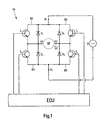
- FIG. 1 shows a circuit arrangement with which a DC motor M can be operated in both directions of rotation can.
- the DC motor M has two connections A1 and A2.
- the transistors T1 to T4 are four diodes D1 to D4 in parallel arranged, the diodes D1 to D4 to the transistors T1 until T4 are polarized in opposite directions.
- the transistor T1 as well 1, the diode D1 is located in an upper left Bridge branch B1, transistor T2 and diode D2 in one upper right bridge branch B2, the transistor T3 and the diode D3 in a lower left bridge arm B3 and the transistor T4 and the diode D4 in a lower right bridge arm B4.
- the transistors T1, T2, T3, T4 behave like switches, who are leaders when there is high potential and who are not are conductive when a deep potential through a Control device (ECU) to the base of the respective transistor T1, T2, T3, T4 is created.
- ECU Control device
- Pulse-width-modulated control of the transistors Stranges the bridge circuit shown in Fig. 2 States Z1 to Z4, which are a supply phase VP and Short circuit phase KP of the DC motor M can be assigned.
- the supply and Short-circuit phases VP and KP as well as the states Z1 to Z4.
- the supply phase VP includes the states Z1 and Z4, in which the transistors T2 are conductive and the transistor T4 is not is switched on.
- the short circuit phase KP includes the States Z2 and Z3 in which the transistor T2 is not conductive and the transistor T4 is turned on. each Switching period T thus contains one supply phase VP and one Short circuit phase KP.
- the state Z1 occurs when the transistor T2 is conductive and the transistor T4 are not turned on. It flows a current from connection U1 via the upper right bridge branch B2 in direction R1 through the DC motor M and over the lower left bridge branch B3 for connection U2. This stream generates a positive air gap torque and drives it DC motor on. In state Z1, the current increases rapidly (Fig. 2) and accelerates the DC motor M.
- the electromotive force causes a reversal of the Current direction. As soon as the current falls below the zero line and flows in the opposite direction, state Z3 begins. The Current now flows through the lower right bridge branch B4 the conducting transistor T4 via the lower left Bridge branch B3 through diode D3 to connection A1.
- the DC motor M acts as a generator. Like the electricity and 2 shows voltage waveforms is the current negative and the voltage jumps again. In this State, the current generates a braking torque in the DC motor M.
- the transistor T2 is conductive and the transistor T4 is switched non-conductive. It state Z4 sets in.
- the DC motor M continues to operate as a generator. Because the short circuit of the state Z3 through the non-conductive transistor T4 is interrupted, the flows Current now in negative direction starting from connection U2 over the lower left bridge branch B3 through the diode D3 over the DC motor M and over the upper right bridge branch B2 through diode D2 to connection U1 of voltage source U. It generates a negative torque and feeds power back to the voltage source U. This becomes possible because the induced voltage positive and the total armature voltage larger than the voltage of the voltage source. Switching the Transistor T2 can be done a little later than the switchover of the transistor T4, since the short-circuit current through the diode D2 flows.
- the current in state Z4 decreases in magnitude until one The direction of the current is reversed in the direction of R1.
- the Voltage waveform from FIG. 2 shows that too Beginning of state Z4 the voltage level to a maximum increases, so that the feedback by the DC motor M is made clear. From the time the direction of the Current in direction R1 occurs again state Z1, in which the DC motor M is actively accelerated again.
- the transistor T2 In analogy to the switching states of the Transistors T1 and T3 and for driving the transistors T2 and T4 are used for an opposite direction of rotation of the DC motor M the transistor T2 permanently on and conductive the transistor T4 is switched permanently to non-conductive.
- the Transistors T1 and T3 are controlled with pulse width modulation.
- the Control signals for the transistors T2 and T4 or T1 and T3 can the duration of the individual states Z1 to Z4 and thus the Length of the supply and short-circuit phase VP or KP varies or be set. It has been shown that by choice a relatively high pulse width ratio P the DC motor M can be operated such that during the supply and short-circuit phase VP or KP only the States Z1 and Z2 occur. In this case the DC motor M mostly accelerated and only slightly slowed down, resulting in a high rated speed and a high Torque can be achieved. With a relatively small one The pulse width ratio P can also be the states Z3 and Z4 occur, resulting in a greater deceleration of the DC motor M and thus to a decrease in the nominal speed and the torque leads.
- the circuit arrangement according to the invention is suitable preferably for switching operations in adjustment devices short switching times since it is long-lasting Operating interval of the DC motor, especially in the Short circuit phase, overheating can occur.
- at automated manual transmissions are only short shift times and therefore only short operating intervals to be expected, with which one Overheating of the DC motor is unlikely.
- Fig. 3 is an adjusting device 12 for the Switching device 14 of a synchronizing device 16 automated manual transmission not shown shown schematically.
- the adjusting device 12 contains a direct current motor M. with a reduction gear 18 and an output shaft 20.
- the DC motor M has two connections A1, A2, the the circuit arrangement 10 according to the invention (FIG. 1) are electrically connected.
- the output shaft 20 is non-rotatable connected to one end 22 of a lever 24.
- a Adjustment pin 28 at the second end 26 of the lever 24 is the Lever 24 with an adjustment groove 30 of the switching device 14 in Intervention.
- the switching device 14 contains a switching rod 32, which with a shift fork 34 is firmly connected. On the shift rod 32, the adjustment groove 30 is introduced, in which the Adjustment pin 28 engages. The shift fork 34 engages in one Shift sleeve 36 of the synchronizer 16 of the Manual transmission.
- a synchronization device 16 mentioned above is preferably based on the " Borg-Warner” system and is widely used in vehicle transmissions.
- G. Lechner and H. Naunheimer for example, in “Vehicle Transmission”, Springer-Verlag Berlin Heidelberg New York, 1994, pages 238-241, provide a detailed description of the structure and mode of operation of such a synchronization device 16 or a synchronization.
- the DC motor M is activated.
- the Reduction gear 18 provides a torque that over the Output shaft 20 engages the lever 24. Due to the Rotary movement of the output shaft 20 leads the second end 26 of the Lever 24 pivots. The swivel movement will via the adjusting pin 28 and the adjusting groove 30 on the Transfer shift rod 32 such that the shift rod 32 performs a translatory adjustment movement and accordingly the directions of the double arrow 38 is moved.
- Direction of rotation of the DC motor M moves Shift rod 32 in one direction or the other Double arrow 38.
- Adjustment movement with regard to adjustment force and adjustment speed to vary because of a synchronization process contains several synchronization sections, one different optimization of the adjustment movement with regard on adjustment force and adjustment speed.
- the Control of the DC motor M with the invention Circuit arrangement 10 with variation of the pulse width ratio P enables such an optimization of the Adjustment.
- a high constant pulse width ratio P1 is selected at the beginning during a switching process, as a result of which high acceleration forces are achieved and the static friction forces of the switching sleeve 36 can be overcome.
- Specified synchronization forces must be observed during a synchronization process in order to avoid damage to the components in the synchronization device. Therefore, after a predefinable acceleration time t A, the pulse width ratio P1 is reduced to a smaller constant pulse width ratio P2. This also prevents the adjustment speed from being too high when an end position of the shift sleeve 36 is reached, which can lead to mechanical damage in the synchronizing device 16.
- the switching device 14 and the Synchronizing device 16 can be optimized.
Abstract
Description
Die Erfindung betrifft eine Schaltungsanordnung zum Betreiben eines Gleichstrommotors und eine Verstelleinrichtung mit einer Schaltungsanordnung zum Betreiben eines Gleichstrommotors, mit Schaltmitteln, die Anschlüsse des Gleichstrommotors mit einer Spannungsquelle pulsweitenmoduliert verbinden.The invention relates to a circuit arrangement for operation a DC motor and an adjustment device with a Circuit arrangement for operating a DC motor, with Switching means, the connections of the DC motor with a Connect voltage source with pulse width modulation.
Es ist bekannt, Verstelleinrichtungen zu automatisieren, indem z.B. Elektromotoren eingesetzt werden, um die Verstelleinrichtungen zu betätigen. Beispielsweise handelt es sich bei derartigen Verstelleinrichtungen um Schalteinrichtungen von Handschaltgetrieben, die durch den Einsatz von Elektromotoren automatisiert betätigt werden. Um eine Überlastung der Schalteinrichtung zu vermeiden, muss die Kraft beim Schalten begrenzt werden. Zur Begrenzung der Schaltkraft werden in derartigen Verstelleinrichtungen üblicherweise federnde Elemente in den Kraftfluss eingebracht, die einen Kraftüberschuss auffangen und/oder es werden z.B. Kraft- oder Positionssensoren eingesetzt, die eine Begrenzung des elektrischen Stroms des Elektromotors auslösen.It is known to automate adjustment devices by e.g. Electric motors are used to control the Actuating devices. For example, it is around such adjustment devices Switching devices of manual gearboxes by the Use of electric motors can be operated automatically. Around To avoid overloading the switching device, the Force when switching can be limited. To limit the Switching force is in such adjustment devices usually spring elements introduced into the power flow, which absorb excess power and / or e.g. Force or position sensors are used which have a limit trigger the electric current of the electric motor.
In der EP 0 638 743 A1 wird beispielsweise ein Verfahren und
eine Vorrichtung zur Steuerung der Schaltkraft in einem
automatisierten mechanischen Getriebe offenbart, wobei ein
Elektromotor eingesetzt wird, der über eine Kontrolleinheit
pulsweitenmoduliert angesteuert wird. Die Kontrolleinheit
steuert bzw. regelt das Tastverhältnis (duty cycle) eines
pulsweitenmodulierten (PWM) Spannungssignals das in
Abhängigkeit vorgegebener Grenzwerte verändert bzw. angepasst
wird. So wird z. B. der Strom während des Schaltvorgangs
überwacht und mit einem zulässigen Zielstromwert verglichen, um
große Stromschwankungen zu vermeiden. Die in der EP 0 638 743
A1 offenbarte Lösung ermöglicht es, eine Drehmomentbegrenzung
und -überwachung eines die Schaltkraft aufbringenden
Gleichstrommotors durchzuführen, um einer mechanischen
Überlastung der Komponenten einer Schaltvorrichtung in einem
automatisierten Getriebe vorzubeugen.For example,
Das Verfahren gemäß der EP 0 638 743 A1 hat den Nachteil, dass
eine Strommessung erforderlich ist, deren Signale in den
Regelungsvorgang einfließen. Dadurch werden sowohl der Aufwand,
als auch die Kosten und das Bauvolumen einer Vorrichtung
deutlich erhöht.The method according to
Die EP 0 126 988 A1 offenbart eine Steuerschaltung zur Drehzahlregelung eines Gleichstrommotors, die einen Drehzahlregelbaustein enthält, der in Abhängigkeit von einem Drehzahlgeber, d.h. in Abhängigkeit von der Motordrehzahl, und einer vorgebbaren Solldrehzahl ein pulsweitenmoduliertes Steuersignal generiert, mit dem eine den Gleichstrommotor speisende Transistorschaltbrücke angesteuert wird. Dabei erzeugt der Drehzahlgeber ein der Drehzahl des Gleichstrommotors proportionales Signal. Dieses Signal wird zur Änderung des Tastverhältnisses eines pulsweitenmodulierten Steuersignals für die Transistorschaltbrücke des Gleichstrommotors herangezogen. Der Gleichstrommotor wird entsprechend des Tastverhältnisses des Steuersignals wechselweise mit einem positiven bzw. negativen Strom versorgt und dadurch wechselweise aktiv beschleunigt bzw. aktiv abgebremst. Durch das aktive Bremsen, d.h. durch das Laden des Gleichstrommotors mit einem der Drehbewegung entgegengesetzten Strom, soll auch bei niedrigen Drehzahlen eine gute Drehzahlregelung und andererseits ein rasches Abbremsen des Motors möglich sein. Die Transistorschaltbrücke ist dabei in bekannter Weise aufgebaut. Es werden vier Transistoren in Brückenschaltung zwischen den Anschlüssen einer Spannungsversorgung einerseits und dem Gleichstrommotor andererseits angeordnet. Durch Ansteuerung der Transistoren werden jeweils zwei der diametral gegenüberliegenden Transistoren der Brückenschaltung leitend bzw. nicht leitend geschaltet. Es ergeben sich somit zwei abwechselnd und gegensinnig mit dem Strom durchflossene Strompfade, die den Gleichstrommotor versorgen. Zur Ansteuerung dieser Stromkreise werden zwei Steuertransistoren verwendet, deren Kollektoren jeweils mit den Basen von zwei Transistoren der Brückenschaltung verbunden sind. An den Basen der Steuertransistoren liegt das vom Drehzahlregelbaustein generierte pulsweitenmodulierte Steuersignal an. Wird einer der beiden Steuertransistoren leitend geschaltet, so fließt Strom durch den Gleichstrommotor über einen der Stromzweige der Transistorschaltbrücke. Durch das pulsweitenmodulierte, wechselweise Schalten der Steuertransistoren wird der Motor abwechselnd in die eine und in die andere Drehrichtung angetrieben. Je nach Pulsweitenverhältnis kann der Antrieb des Gleichstrommotors in eine Drehrichtung überwiegen, wodurch die Drehzahl des Motors beeinflussbar wird.EP 0 126 988 A1 discloses a control circuit for Speed control of a DC motor, the one Includes speed control module that is dependent on one Speed sensor, i.e. depending on the engine speed, and a pulse-width modulated at a predefinable target speed Control signal generated with which the DC motor feeding transistor switching bridge is controlled. there the speed sensor generates a speed of the DC motor proportional signal. This signal becomes Change the duty cycle of a pulse width modulated Control signal for the transistor switching bridge of the DC motor used. The DC motor will according to the duty cycle of the control signal alternately supplied with a positive or negative current and thereby alternately actively accelerated or active braked. Through active braking, i.e. by loading the DC motor with one opposite to the rotary movement Electricity is said to be good even at low speeds Speed control and on the other hand a quick braking of the Motors may be possible. The transistor jumper is in known way built. There are four transistors in Bridge circuit between the connections of one Power supply on the one hand and the DC motor otherwise arranged. By controlling the transistors are two of the diametrically opposite Transistors of the bridge circuit conductive or non-conductive connected. So there are two alternating and opposing current paths through which the Supply DC motor. To control these circuits two control transistors are used, their collectors each with the bases of two transistors Bridge circuit are connected. At the bases of the Control transistors are from the speed control module generated pulse width modulated control signal. Will one of the two control transistors switched on, then flows Current through the DC motor through one of the branches of the Transistor switching bridge. Due to the pulse width modulated, alternately switching the control transistors becomes the engine alternating in one and in the other direction driven. Depending on the pulse width ratio, the drive of the DC motor predominate in one direction of rotation, whereby the Engine speed can be influenced.
Die in der EP 0 126 988 A1 offenbarte Lösung zur
Drehzahlregelung eines Elektromotors geht von einer Schaltung
mit zwei ansteuerbaren Stromkreisen aus, die zum Antrieb des
Gleichstrommotors im Wechsel zueinander angesteuert werden.
Nachteilig wirkt sich dabei aus, dass die dazu benötigte
Drehzahlregelung aufwändig und kostspielig ist, zumal
zusätzlich Komponenten wie z.B. ein Drehzahlgeber und eine
logische Anordnung zur Signalverknüpfung benötigt werden. The solution to
Bei den beschriebenen Vorrichtungen bzw. Verfahren wird jeweils eine Betriebsgröße des Gleichstrommotors gesteuert bzw. beschränkt. Eine Begrenzung sowohl des Drehmomentes als auch der Drehzahl eines Gleichstrommotors ist mit den bekannten Vorrichtungen bzw. Verfahren nicht möglich.In the described devices and methods, respectively controlled an operating variable of the DC motor or limited. A limitation of both torque and the speed of a DC motor is with the known Devices or processes not possible.
Die der Erfindung zugrunde liegende Aufgabe wird darin gesehen,
eine Schaltungsanordnung zum Betreiben eines Gleichstrommotors
und eine Verstelleinrichtung mit einer Schaltungsanordnung zum
Betreiben eines Gleichstrommotors der eingangs genannten Art
anzugeben, durch welches die vorgenannten Probleme überwunden
werden. Insbesondere soll die Schaltungsanordnung derart
ausgebildet werden, dass eine vorgebbare Nenndrehzahl und ein
vorgebbares Drehmoment des Gleichstrommotors nicht
überschritten wird. Dabei sollen keine Sensoren oder
Einrichtungen zur Weg-/Drehzahl- oder Kraftmessung bzw. zur
Strombegrenzung des Gleichstrommotors erforderlich sein.
Andererseits soll die Verstellung, insbesondere des
Schaltvorgangs, so schnell wie irgend möglich vorgenommen
werden können, ohne dass es durch überhöhte Geschwindigkeiten
beim Erreichen von Endanschlägen zu Beschädigungen kommt. Des
Weiteren soll es die Schaltungsanordnung ermöglichen, auf eine
Kraftbegrenzung durch zusätzliche federnde Elemente in der
Verstelleinrichtung zu verzichten. Der Erfindung liegt weiter
die Aufgabe zugrunde, durch die Schaltungsanordnung die
Verstellzeiten der Verstelleinrichtung zu minimieren bzw. die
Betätigungsgeschwindigkeit der Verstelleinrichtung im Rahmen
der Belastbarkeit der mechanischen Elemente der
Verstelleinrichtung zu optimieren.
Die Aufgabe wird erfindungsgemäß durch die Lehre des
Patentanspruchs 1 bzw. 7 gelöst. Weitere vorteilhafte
Ausgestaltungen und Weiterbildungen der Erfindung gehen aus den
Unteransprüchen hervor.The object on which the invention is based is seen in specifying a circuit arrangement for operating a DC motor and an adjustment device with a circuit arrangement for operating a DC motor of the type mentioned at the outset, by means of which the aforementioned problems are overcome. In particular, the circuit arrangement should be designed such that a predeterminable nominal speed and a predeterminable torque of the DC motor are not exceeded. No sensors or devices for displacement / speed or force measurement or for limiting the current of the DC motor should be required. On the other hand, the adjustment, in particular the switching operation, should be able to be carried out as quickly as possible without causing excessive speeds when end stops are reached. Furthermore, the circuit arrangement should make it possible to dispense with a force limitation by means of additional resilient elements in the adjusting device. The invention is further based on the object of minimizing the adjustment times of the adjustment device by means of the circuit arrangement or optimizing the actuation speed of the adjustment device within the load-bearing capacity of the mechanical elements of the adjustment device.
The object is achieved by the teaching of claims 1 and 7, respectively. Further advantageous refinements and developments of the invention emerge from the subclaims.
Erfindungsgemäß wird eine Schaltungsanordnung vorgeschlagen, in der Schaltmittel vorgesehen sind, die derart angeordnet und geschaltet werden, dass die Anschlüsse eines Gleichstrommotors innerhalb eines Schaltzyklus abwechselnd einerseits in einer Versorgungsphase mit einer Spannungsquelle verbunden und andererseits in einer Kurzschlussphase kurzgeschlossen werden, wobei sich durch die abwechselnden Versorgungs- und Kurzschlussphasen Betriebszustände einstellen können, in denen der Motor alternierend angetrieben und abgebremst wird. Insbesondere wird durch ein pulsweitenmoduliertes Steuersignal zur Ansteuerung der Schaltmittel der Gleichstrommotor wechselweise beschleunigt und abgebremst, so dass ein Gleichgewichtszustand erzielt wird, in dem sich eine vorgebbare Nenndrehzahl zum einen, zum anderen ein vorgebbares Drehmoment einstellt. In der Versorgungsphase wird der Gleichstrommotor von einer Spannungsquelle angetrieben. Es folgt die Kurzschlussphase, die zunächst bewirkt, dass Strom in gleicher Richtung durch den Gleichstrommotor fließt, jedoch der Stromfluss abnimmt. Dabei wird der Gleichstrommotor weiterhin angetrieben. Wird der Punkt erreicht, an dem die elektromotorische Kraft des Gleichstrommotors überwiegt, kommt es zu einer Stromumkehr und der Gleichstrommotor wirkt als Generator. In dieser Phase wird der Gleichstrommotor infolge des Kurzschlussstroms stark abgebremst. Wird nun wieder in die Versorgungsphase geschaltet, fließt der Strom durch den Gleichstrommotor zunächst weiter in gleicher Richtung und wird zurück zur Spannungsquelle geleitet, d. h. es erfolgt eine kurzzeitige Stromrückspeisung. Das heißt, durch Umschalten von der Kurzschlussphase in die Versorgungsphase kann ein Teil der im System enthaltenen kinetischen mechanischen Energie in elektrische Energie zurückgewandelt und in die Spannungsquelle gespeist werden.According to the invention, a circuit arrangement is proposed in of the switching means are provided, which are arranged and be switched that the connections of a DC motor alternately on the one hand within a switching cycle Supply phase connected to a voltage source and on the other hand are short-circuited in a short-circuit phase, being characterized by the alternating supply and Short-circuit phases can set operating states in which the motor is driven and braked alternately. In particular, a pulse-width modulated control signal to control the switching means of the DC motor alternately accelerated and braked so that a Equilibrium state is achieved in which there is a predetermined Nominal speed, on the one hand, and a specifiable torque on the other established. The DC motor is in the supply phase powered by a voltage source. The follows Short circuit phase, which initially causes current in the same Direction flows through the DC motor, however the Current flow decreases. The DC motor will continue to do so driven. The point is reached at which the electromotive force of the DC motor predominates, comes there is a current reversal and the DC motor acts as Generator. In this phase, the DC motor is due of the short-circuit current braked strongly. Will now be back in the Switched supply phase, the current flows through the DC motor initially continues in the same direction and will directed back to the voltage source, d. H. there is a short-term power recovery. That is, by switching from The short circuit phase in the supply phase can be part of the kinetic mechanical energy in the system electrical energy converted back into the voltage source be fed.
Durch Variation des Tastverhältnisses (duty cycle) des pulsweitenmodulierten Steuersignals können sowohl die Nenndrehzahl bzw. eine maximale Drehzahl als auch das maximale Drehmoment des Gleichstrommotors gezielt vorgegeben werden, ohne das eine aufwändige Sensorik zur Bestimmung von Betriebsgrößen (wie z.B. Motordrehzahl oder Motorstrom) herangezogen werden muss. Abhängig von dem Verhältnis der Länge der Versorgungsphase zur Länge der Kurzschlussphase innerhalb eines Schaltzyklus lassen sich Nenndrehzahlen und Drehmomente einstellen.By varying the duty cycle of the Pulse width modulated control signal can both Nominal speed or a maximum speed as well as the maximum Torque of the DC motor can be specified in a targeted manner, without the complex sensor technology for determining Operating variables (such as motor speed or motor current) must be used. Depending on the ratio of length the supply phase to the length of the short circuit phase within A switching cycle can be rated speeds and torques to adjust.
In einer vorteilhaften Ausbildung der Erfindung wird der Gleichstrommotor in einem Zeitintervall zwischen der Versorgungsphase und der Kurzschlussphase in einer offenen Phase betrieben, derart dass die Schaltmittel der Schaltungsanordnung des Gleichstrommotors gleichzeitig nicht leitend geschaltet sind. Dies ist vorgesehen, um Spannungsspitzen zu vermeiden, die durch undiskrete Schaltvorgänge von der Versorgungsphase in die Kurzschlussphase entstehen können. Durch das Einbringen einer offenen Phase in den Schaltzyklus können Überschneidungen ungewollter Schaltzustände vermieden werden.In an advantageous embodiment of the invention, the DC motor in a time interval between the Supply phase and the short circuit phase in an open Phase operated such that the switching means of the Circuit arrangement of the DC motor at the same time not are switched on. This is intended to Avoid spikes caused by undiscreet Switching operations from the supply phase to the Short circuit phase can arise. By introducing one open phase in the switching cycle can overlap unwanted switching states can be avoided.
In einer erfindungsgemäßen Ausbildung der Schaltungsanordnung werden vorzugsweise, elektrische oder elektronische Schaltmittel verwendet, wie Relais oder Halbleiterbausteine. Als Halbleiterbausteine kommen z.B. Transistoren, MOSFETs oder IGBTs in Betracht, denen gegebenenfalls weitere Halbleiterbausteine wie z.B. Dioden parallelgeschaltet sind. Insbesondere für das erfindungsgemäße Betreiben des Gleichstrommotors, mit einer durch pulsweitenmoduliertem Steuersignal erzeugten Schaltfrequenz von vorzugsweise 500 Hz, ist der Einsatz von Halbleiterbausteinen von Vorteil bzw. notwendig.In an embodiment of the circuit arrangement according to the invention are preferred, electrical or electronic Switching means used, such as relays or semiconductor devices. The semiconductor components are e.g. Transistors, MOSFETs or IGBTs, which may include others Semiconductor devices such as Diodes are connected in parallel. In particular for the operation of the invention DC motor, with a pulse width modulated Control signal generated switching frequency of preferably 500 Hz, is the use of semiconductor components an advantage or necessary.
In einer besonders vorteilhaften Ausbildung der Erfindung zum Betreiben des Gleichstrommotors in einer ersten Drehrichtung, sind in der Schaltungsanordnung wenigstens zwei gleichsinnig in Serie geschaltete Transistoren mit jeweils gegenläufig parallelgeschalteten Dioden enthalten. Die Schaltungsanordnung ist hierbei wie folgt aufgebaut: Ein erster Anschluss der Spannungsquelle steht mit einem ersten Anschluss des Gleichstrommotors über einen ersten in Richtung des Gleichstrommotors durchlässigen Transistor schaltbar in Verbindung. Ein zweiter Anschluss des Gleichstrommotors ist mit einem zweiten Anschluss der Spannungsquelle verbunden. Der erste Anschluss des Gleichstrommotors steht des Weiteren über einen zweiten in Richtung des zweiten Anschlusses der Spannungsquelle durchlässigen Transistor mit dem zweiten Anschluss des Gleichstrommotors schaltbar in Verbindung.In a particularly advantageous embodiment of the invention for Operating the DC motor in a first direction of rotation, are at least two in the same direction in the circuit arrangement transistors connected in series, each with opposite directions parallel diodes included. The circuit arrangement is structured as follows: A first connection of the Voltage source is available with a first connection of the DC motor via a first in the direction of DC motor permeable transistor switchable in Connection. A second connection of the DC motor is connected to a second connection of the voltage source. The The first connection of the DC motor is also protruding a second towards the second port of the Voltage source permeable transistor with the second Connection of the DC motor switchable in connection.
Diese Schaltungsanordnung ermöglicht es, durch pulsweitenmodulierte Ansteuerung der beiden Transistoren den Gleichstrommotor alternierend in einer Versorgungsphase, nämlich wenn der erste Transistor leitend und der zweite Transistor nicht leitend geschaltet ist, und in einer Kurzschlussphase, nämlich wenn der erste Transistor nicht leitend und der zweite Transistor leitend geschaltet ist, zu betreiben. Durch vorgebbare Pulsweitenverhältnisse der Steuersignale für die Transistoren stellen sich entsprechende Betriebszustände im Gleichstrommotor ein, in denen der Gleichstrommotor alternierend abgebremst und angetrieben wird, wodurch sich ein Gleichgewichtszustand einstellt, in dem eine vorgebbare Nenndrehzahl nicht überschritten wird.This circuit arrangement enables through pulse width modulated control of the two transistors DC motor alternately in a supply phase, namely when the first transistor is conductive and the second Transistor is not turned on, and in a Short circuit phase, namely when the first transistor is not is conductive and the second transistor is turned on operate. Through predeterminable pulse width ratios of Control signals for the transistors are set accordingly Operating states in the DC motor in which the DC motor is alternately braked and driven, which creates an equilibrium state in which a Predeterminable nominal speed is not exceeded.
Diese Ausbildung der Erfindung unterscheidet sich wesentlich
vom Stand der Technik. Bei der EP 0 126 988 A1 wird eine
Brückentransistorschaltung verwendet, in der jeweils zwei
diametral gegenüberliegende Transistoren gleichsinnig
geschaltet werden, wodurch zwei Strompfade abwechselnd
geöffnet bzw. geschlossen werden, so dass der Stromfluss durch
den Gleichstrommotor alternierend in positiver und in
negativer Richtung erfolgt und der Motor durch den Strom
abwechselnd angetrieben und abgebremst wird. Bei der
vorliegenden Erfindung ist hingegen lediglich ein Strompfad
mit zwei Transistoren erforderlich. Der Gleichstrommotor wird
alternierend mit der Spannungsquelle verbunden und in einen
Kurzschlusskreis geschaltet. Die erfindungsgemäße
Schaltungsanordnung enthält wenige Bauteile und hat einen
einfachen Aufbau. Bei ihr kann vollständig auf den Einsatz von
Sensoren verzichtet werden.This embodiment of the invention differs significantly
from the state of the art.
In einer weiteren besonders vorteilhaften Ausbildung zum
Betreiben des Gleichstrommotors in beide Drehrichtungen werden
wenigstens vier Transistoren mit jeweils gegenläufig
parallelgeschalteten Dioden in einer Schaltung angeordnet.
Hierbei steht ein erster Anschluss der Spannungsquelle mit
einem ersten bzw. einem zweiten Anschluss des
Gleichstrommotors über einen ersten bzw. einen zweiten
Transistor schaltbar in Verbindung. Des Weiteren steht der
erste bzw. der zweite Anschluss des Gleichstrommotors mit dem
zweiten Anschluss der Spannungsquelle über einen dritten bzw.
einen vierten Transistor schaltbar in Verbindung, wobei alle
Transistoren bezüglich der Spannungsquelle die gleiche
Durchlassrichtung aufweisen. Eine derartige Schaltungsanordnung
entspricht einer Brückenschaltung von Transistoren
bzw. Dioden. Auch diese erfindungsgemäße Brückenschaltung
unterscheidet sich erheblich vom Stand der Technik, wie er in
der EP 0 126 988 A1 beschrieben wurde, denn erfindungsgemäß
wird für eine Drehrichtung lediglich das Transistorenpaar
eines Strompfades wechselweise umgeschaltet, während hierbei
das Transistorenpaar des anderen Strompfades nicht geschaltet
wird, sondern für die andere Drehrichtung zur Verfügung steht.In a further particularly advantageous training for
Operate the DC motor in both directions
at least four transistors, each running in opposite directions
parallel connected diodes arranged in a circuit.
Here is a first connection of the voltage source
a first or a second connection of the
DC motor via a first or a second
Switchable transistor in connection. Furthermore, the
first or second connection of the DC motor with the
second connection of the voltage source via a third or
a fourth transistor switchable in connection, all
Transistors with respect to the voltage source the same
Have forward direction. Such a circuit arrangement
corresponds to a bridge circuit of transistors
or diodes. This bridge circuit according to the invention
differs significantly from the state of the art as in
Des Weiteren besitzt die erfindungsgemäße Schaltungsanordnung den Vorteil, dass die Phasen, in denen der Gleichstrommotor abgebremst wird, sich desto weniger auswirken, je langsamer der Gleichstrommotor läuft. Dadurch kann eine vorgebbare Nenndrehzahl aus dem Stillstand sehr schnell erreicht werden. Andererseits tritt eine durch die Kurzschlussphase hervorgerufene Bremswirkung nur ein, wenn der Gleichstrommotor sich dreht. Die Bremswirkung ist umso stärker, je schneller sich der Gleichstrommotor dreht. Wenn sich der Gleichstrommotor frei ohne nennenswerte Drehmomentbelastung drehen kann, dann beschleunigt er in der Versorgungsphase und wird in der Kurzschlussphase etwa gleichstark wieder abgebremst. Dabei stellt sich ein Gleichgewicht aus Antreiben und Bremsen ein.Furthermore, the circuit arrangement according to the invention has the advantage that the phases in which the DC motor is slowed down, the less impact, the slower the DC motor is running. This allows a predeterminable Nominal speed can be reached very quickly from standstill. On the other hand, one enters through the short circuit phase induced braking effect only when the DC motor turns. The faster the car brakes, the stronger it is the DC motor turns. If the DC motor free without significant torque load can turn, then it accelerates in the supply phase and becomes roughly equal again in the short circuit phase braked. This creates a balance of driving and braking.
In einer bevorzugten Ausführung der Schaltungsanordnung sind die ansteuerbaren Schaltmittel (z.B. Transistoren) beim Betreiben des Gleichstrommotors über die Zeit mit variablen Pulsweitenverhältnissen ansteuerbar. Dadurch kann während eines Schaltvorgangs gezielt auf die vorherrschenden Betriebsbedingungen eingegangen werden. So kann beispielsweise zum Beschleunigen von Massen ein hohes Pulsweitenverhältnis gewählt werden, um eine rasche Beschleunigung mit hohem Drehmoment zu erreichen. Im weiteren Verlauf kann dann zum Halten einer gewünschten Nenndrehzahl das Pulsweitenverhältnis wieder herabgesetzt werden. Durch entsprechend geringe Pulsweitenverhältnisse können selbst mit leistungsstarken Gleichstrommotoren geringe Drehmomente oder Haltekräfte kontrolliert aufgebracht werden. Durch Variation des Pulsweitenverhältnisses über die Zeit wird es ermöglicht, die Ansteuerung des Gleichstrommotors während eines Schaltvorgangs individuell an die vorherrschenden Bedingungen anzupassen und hinsichtlich der Dauer eines Schaltvorgangs zu optimieren.In a preferred embodiment of the circuit arrangement the controllable switching means (e.g. transistors) at Operating the DC motor over time with variable Pulse width ratios can be controlled. This allows during of a switching process aimed at the prevailing Operating conditions. For example a high pulse width ratio to accelerate masses be chosen to accelerate rapidly with high To achieve torque. In the further course can then Maintaining a desired nominal speed the pulse width ratio be reduced again. By correspondingly low Pulse width ratios can even with powerful DC motors low torques or holding forces applied in a controlled manner. By varying the Pulse width ratio over time is made possible by the Control of the DC motor during a switching process adapt individually to the prevailing conditions and optimize with regard to the duration of a switching operation.
Die erfindungsgemäße Schaltungsanordnung eignet sich unter anderem für den Einsatz in Verstelleinrichtungen, bei denen ein Gleichstrommotor zur Automatisierung des Verstellvorganges eingesetzt wird. Die erfindungsgemäße Schaltungsanordnung eignet sich insbesondere für elektromotorunterstützte Verstelleinrichtungen mit begrenzten Verstellwegen bzw. für Verstelleinrichtungen, bei denen ein Verstellweg durch Anschläge oder dergleichen begrenzt ist.The circuit arrangement according to the invention is suitable under other for use in adjustment devices where a DC motor to automate the adjustment process is used. The circuit arrangement according to the invention is particularly suitable for electric motor assisted Adjustment devices with limited adjustment paths or for Adjustment devices in which an adjustment path through Attacks or the like is limited.
Um derartige Verstelleinrichtungen handelt es sich bei Verstelleinrichtungen halbautomatisierter Schaltgetriebe, bei denen der Verstellweg durch eine Synchronisiereinrichtung des Schaltgetriebes begrenzt ist und die Schalteinrichtung während eines Synchronisiervorgangs gegen einen Anschlag bzw. gegen Synchronisierringe fährt. Um einen raschen Schaltvorgang zu erreichen, werden hierbei vergleichsweise leistungsstarke Schaltmotoren eingesetzt. Bei Erreichen des Anschlages müssen die durch den Elektromotor aufgebrachten Schaltkräfte begrenzt werden, damit einzelne Komponenten der Verstelleinrichtung und der Synchronisiereinrichtung nicht beschädigt werden. Aus Kostengründen und um derartige Baugruppen möglichst klein zu halten ist es sinnvoll, zusätzliche Sensoren zur Schaltkraftbegrenzung oder kraftaufnehmende federnde Zusatzelemente zu vermeiden. Durch Einsatz einer erfindungsgemäßen Schaltungsanordnung für einen Gleichstrommotor einer Verstelleinrichtung eines automatisierten Schaltgetriebes ist eine Schaltkraftbegrenzung durch pulsweitenmodulierte Ansteuerung der Schaltungsanordnung möglich.Such adjustment devices are Adjustment devices semi-automatic gearbox, at which the adjustment path by a synchronizer Manual gearbox is limited and the switching device during a synchronization process against a stop or against Synchronizer rings moves. To ensure a quick shift achieve comparatively powerful Switch motors used. When the stop is reached limits the switching forces applied by the electric motor so that individual components of the adjustment device and the synchronization device are not damaged. Out Cost reasons and in order to keep such assemblies as small as possible it makes sense to use additional sensors Switching force limitation or resilient force-absorbing Avoid additional elements. By using a Circuit arrangement according to the invention for a DC motor an adjusting device of an automated Manual gearbox is limited by a switching force Pulse-width-modulated control of the circuit arrangement possible.
Wird beispielsweise die Drehbewegung des Gleichstrommotors behindert, weil die Synchronisiereinrichtung zur Anlage gekommen ist, baut sich in der Versorgungsphase eine Kraft auf, die in der Kurzschlussphase nicht oder nur wenig abgebaut wird, da bei Stillstand des Gleichstrommotors in der Kurzschlussphase dem System aktiv keine Energie entzogen wird. Durch geeignete Wahl des Pulsweitenverhältnisses mit dem die Schaltungsanordnung angesteuert wird, können Frequenz und Zeitdauer von Versorgungs- und Kurzschlussphase gesteuert werden und damit Schaltkräfte in der Schalteinrichtung begrenzt werden.For example, the rotary motion of the DC motor hindered because the synchronization device to the system a force builds up in the supply phase, which is not or only slightly reduced in the short circuit phase, there when the DC motor is at a standstill in the short circuit phase no energy is actively withdrawn from the system. By suitable Choice of the pulse width ratio with which the circuit arrangement frequency and duration of Supply and short circuit phase can be controlled and thus Switching forces in the switching device are limited.
Anhand der Zeichnung, die ein Ausführungsbeispiel der erfindungsgemäßen Schaltungsanordnung und ein Ausführungsbeispiel der erfindungsgemäßen Verstelleinrichtung mit einer Schaltungsanordnung zeigt, werden nachfolgend die Erfindung sowie weitere Vorteile und vorteilhafte Weiterbildungen und Ausgestaltungen der Erfindung näher beschrieben und erläutert.Based on the drawing, which is an embodiment of the Circuit arrangement according to the invention and an embodiment the adjustment device according to the invention with a Circuitry shows the invention below as well as further advantages and advantageous further training and Embodiments of the invention described and explained in more detail.
Es zeigt:
- Fig. 1
- das Schaltbild einer erfindungsgemäßen Schaltungsanordnung für einen Gleichstrommotor,
- Fig. 2
- ein schematisches Schaltimpulsdiagramm mit korrespondierenden Strom- und Spannungssignalen des Gleichstrommotors,
- Fig. 3
- eine schematische Darstellung einer erfindungsgemäßen Verstelleinrichtung für ein Schaltgetriebe und
- Fig. 4
- ein Zeitdiagramm einer bevorzugten Variation eines Pulsweitenverhältnisses eines Steuersignals während eines Schaltvorgangs in einem automatisierten Schaltgetriebe.
- Fig. 1
- the circuit diagram of a circuit arrangement according to the invention for a DC motor,
- Fig. 2
- 1 shows a schematic switching pulse diagram with corresponding current and voltage signals of the direct current motor,
- Fig. 3
- a schematic representation of an adjustment device according to the invention for a manual transmission and
- Fig. 4
- a timing diagram of a preferred variation of a pulse width ratio of a control signal during a shift in an automated transmission.
Aus Fig. 1 geht eine Schaltungsanordnung hervor, mit der ein Gleichstrommotor M in beide Drehrichtungen betrieben werden kann. Der Gleichstrommotor M besitzt zwei Anschlüsse A1 und A2.1 shows a circuit arrangement with which a DC motor M can be operated in both directions of rotation can. The DC motor M has two connections A1 and A2.
Zwischen den beiden Anschlüssen U1, U2 einer Spannungsquelle U sind zwei Transistoren T1, T3 in Reihe in einem ersten Strang und parallel hierzu sind zwei Transistoren T2, T4 in Reihe in einem zweiten Strang angeordnet. Alle vier Transistoren sind gleichsinnig gepolt und bilden eine Brückenschaltung, bei der die Anschlüsse A1, A2 des Gleichstrommotors M leitend, mit jeweils einem Mittelabgriff zwischen den Transistoren T1 und T3 bzw. zwischen den Transistoren T2 und T4, verbunden sind. Zu den Transistoren T1 bis T4 sind vier Dioden D1 bis D4 parallel angeordnet, wobei die Dioden D1 bis D4 zu den Transistoren T1 bis T4 entgegengerichtet gepolt sind. Der Transistor T1 sowie die Diode D1 befinden sich gemäß Fig. 1 in einem oberen linken Brückenzweig B1, der Transistor T2 und die Diode D2 in einem oberen rechten Brückenzweig B2, der Transistor T3 und die Diode D3 in einem unteren linken Brückenzweig B3 und der Transistor T4 und die Diode D4 in einem unteren rechten Brückenzweig B4. Die Transistoren T1, T2, T3, T4 verhalten sich wie Schalter, die leitend sind, wenn ein hohes Potential, und die nicht leitend sind, wenn ein tiefes Potential durch eine Steuereinrichtung (ECU) an die Basis des jeweiligen Transistors T1, T2, T3, T4 angelegt wird.Between the two connections U1, U2 of a voltage source U are two transistors T1, T3 in series in a first strand and in parallel with this are two transistors T2, T4 in series arranged in a second strand. All four transistors are polarized in the same direction and form a bridge circuit in which the connections A1, A2 of the direct current motor M conductive, with one center tap between transistors T1 and T3 or between the transistors T2 and T4. To The transistors T1 to T4 are four diodes D1 to D4 in parallel arranged, the diodes D1 to D4 to the transistors T1 until T4 are polarized in opposite directions. The transistor T1 as well 1, the diode D1 is located in an upper left Bridge branch B1, transistor T2 and diode D2 in one upper right bridge branch B2, the transistor T3 and the diode D3 in a lower left bridge arm B3 and the transistor T4 and the diode D4 in a lower right bridge arm B4. The transistors T1, T2, T3, T4 behave like switches, who are leaders when there is high potential and who are not are conductive when a deep potential through a Control device (ECU) to the base of the respective transistor T1, T2, T3, T4 is created.
Für den Betrieb des Gleichstrommotors M in eine Drehrichtung ergeben sich Schaltzustände, die in eine Versorgungsphase und in eine Kurzschlussphase des Gleichstrommotors resultieren. Für eine erste Drehrichtung des Gleichstrommotors M werden die Transistoren T1 und T3 pulsweitenmoduliert wechselweise geschaltet, wobei der Transistor T2 dauerhaft nicht leitend und der Transistor T4 dauerhaft leitend geschaltet ist. Für die zweite Drehrichtung werden die Transistoren T2 und T4 pulsweitenmoduliert wechselweise geschaltet und dabei der Transistor T1 dauerhaft nicht leitend und der Transistor T3 dauerhaft leitend geschaltet. Es werden also je nach Drehrichtung immer nur die Transistoren eines Stranges der Brückenschaltung (Längs-Brückenzweig) gegensinnig pulsweitenmoduliert angesteuert. Dabei ist zu beachten, dass die beiden Transistoren eines Stranges (T1 und T3 bzw. T2 und T4) nie gleichzeitig leitend geschaltet werden, da dies zu einem Kurzschluss der Spannungsquelle führen würde.For operating the DC motor M in one direction of rotation switching states result in a supply phase and result in a short circuit phase of the DC motor. For a first direction of rotation of the DC motor M Transistors T1 and T3 alternately pulse width modulated switched, the transistor T2 permanently non-conductive and the transistor T4 is permanently switched on. For the transistors T2 and T4 become the second direction of rotation pulse width modulated switched alternately and the Transistor T1 permanently non-conductive and transistor T3 permanently switched on. So it will depend on Direction of rotation always only the transistors of one strand of Bridge circuit (longitudinal bridge branch) pulse width modulated in opposite directions driven. It should be noted that the two Transistors of one strand (T1 and T3 or T2 and T4) never be turned on at the same time, as this becomes a Short circuit of the voltage source would result.
Für eine ausgewählte Drehrichtung ergeben sich durch pulsweitenmodulierte Ansteuerung der Transistoren eines Stranges der Brückenschaltung die in Fig. 2 dargestellten Zustände Z1 bis Z4, welche einer Versorgungsphase VP und einer Kurzschlussphase KP des Gleichstrommotors M zugeordnet werden.For a selected direction of rotation, Pulse-width-modulated control of the transistors Stranges the bridge circuit shown in Fig. 2 States Z1 to Z4, which are a supply phase VP and Short circuit phase KP of the DC motor M can be assigned.
In der Fig. 2 sind die Steuersignale für die pulsweitenmodulierte Ansteuerung der Transistoren T2 und T4 mit einem Pulsweitenverhältnis von 40% sowie die Strom- und Ankerspannungssignale des Gleichstrommotors M dargestellt. Ebenfalls eingetragen sind sowohl die Versorgungs- und Kurzschlussphasen VP und KP als auch die Zustände Z1 bis Z4. Die Versorgungsphase VP umfasst die Zustände Z1 und Z4, in denen die Transistoren T2 leitend und der Transistor T4 nicht leitend geschaltet ist. Die Kurzschlussphase KP umfasst die Zustände Z2 und Z3, in denen der Transistoren T2 nicht leitend und der Transistor T4 leitend geschaltet ist. Jede Schaltperiode T enthält somit eine Versorgungsphase VP und eine Kurzschlussphase KP.2 are the control signals for the Pulse width modulated control of the transistors T2 and T4 with a pulse width ratio of 40% and the current and Armature voltage signals of the DC motor M shown. Both the supply and Short-circuit phases VP and KP as well as the states Z1 to Z4. The supply phase VP includes the states Z1 and Z4, in which the transistors T2 are conductive and the transistor T4 is not is switched on. The short circuit phase KP includes the States Z2 and Z3 in which the transistor T2 is not conductive and the transistor T4 is turned on. each Switching period T thus contains one supply phase VP and one Short circuit phase KP.
Der Zustand Z1 stellt sich ein, wenn der Transistor T2 leitend und der Transistor T4 nicht leitend geschaltet sind. Es fließt ein Strom vom Anschluss U1 über den oberen rechten Brückenzweig B2 in Richtung R1 durch den Gleichstrommotor M und über den unteren linken Brückenzweig B3 zum Anschluss U2. Dieser Strom erzeugt ein positives Luftspaltmoment und treibt den Gleichstrommotor an. Im Zustand Z1 nimmt der Strom rasch zu (Fig. 2) und beschleunigt den Gleichstrommotor M.The state Z1 occurs when the transistor T2 is conductive and the transistor T4 are not turned on. It flows a current from connection U1 via the upper right bridge branch B2 in direction R1 through the DC motor M and over the lower left bridge branch B3 for connection U2. This stream generates a positive air gap torque and drives it DC motor on. In state Z1, the current increases rapidly (Fig. 2) and accelerates the DC motor M.
Durch die Umschaltung der Transistoren T2 und T4 stellt sich der Zustand Z2 ein, in welchem der Transistor T2 nicht leitend und der Transistor T4 leitend geschaltet ist, so dass der Gleichstrommotor M in der Kurzschlussphase KP betrieben wird, d.h. die Anschlüsse A1, A2 des Gleichstrommotors M sind kurzgeschlossen. Aufgrund seines Trägheitsmoments dreht sich der Gleichstrommotor M weiter und infolge der Ankerinduktion fließt der Strom weiter in dieselbe Richtung R1 gegen die in den Motorwindungen induzierte Gegenspannung über den unteren linken Brückenzweig B3 durch den leitend geschalteten Transistor T3 und über den unteren rechten Brückenzweig durch die Diode D4 zum Anschluss A2. Dem Stromfluss wirkt die in den Motorwindungen induzierte Spannung entgegen, so dass der Strom rasch abnimmt. Die Umschaltung des Transistors T4 kann etwas später erfolgen als die Umschaltung des Transistors T2, da der Kurzschlussstrom zunächst durch die Diode D4 fließt.By switching the transistors T2 and T4 the state Z2 in which the transistor T2 is not conductive and the transistor T4 is turned on, so that the DC motor M is operated in the short circuit phase KP, i.e. the connections A1, A2 of the direct current motor M are shorted. Due to its moment of inertia, it rotates the DC motor M continues and as a result of armature induction the current continues to flow in the same direction R1 against that in the motor windings induced counter voltage across the lower one left bridge branch B3 through the switched Transistor T3 and through the lower right bridge branch the diode D4 for connection A2. The current flow acts in the Motor windings induced opposite voltage, so the current decreases rapidly. Switching transistor T4 can do something later than the switching of the transistor T2, since the Short-circuit current initially flows through diode D4.
Die elektromotorische Kraft bewirkt eine Umkehr der Stromrichtung. Sobald der Strom die Nulllinie unterschreitet und in die Gegenrichtung fließt, beginnt der Zustand Z3. Der Strom fließt nun über den unteren rechten Brückenzweig B4 durch den leitend geschalteten Transistor T4 über den unteren linken Brückenzweig B3 durch die Diode D3 zum Anschluss A1. Der Gleichstrommotor M wirkt hierbei als Generator. Wie die Stromund Spannungssignalverläufe in Fig. 2 zeigen, ist der Strom negativ und es kommt erneut zu einem Spannungssprung. In diesem Zustand erzeugt der Strom ein Bremsmoment im Gleichstrommotor M.The electromotive force causes a reversal of the Current direction. As soon as the current falls below the zero line and flows in the opposite direction, state Z3 begins. The Current now flows through the lower right bridge branch B4 the conducting transistor T4 via the lower left Bridge branch B3 through diode D3 to connection A1. The DC motor M acts as a generator. Like the electricity and 2 shows voltage waveforms is the current negative and the voltage jumps again. In this State, the current generates a braking torque in the DC motor M.
Durch erneutes Ansteuern der Transistoren T2 und T4 wird wieder in die Versorgungsphase VP geschaltet. Der Transistor T2 wird leitend und der Transistor T4 wird nicht leitend geschaltet. Es stellt sich Zustand Z4 ein. Der Gleichstrommotor M wirkt weiter als Generator. Da der Kurzschlusskreis des Zustandes Z3 durch den nicht leitenden Transistor T4 unterbrochen ist, fließt der Strom jetzt in negativer Richtung ausgehend vom Anschluss U2 über den unteren linken Brückenzweig B3 durch die Diode D3 über den Gleichstrommotor M und über den oberen rechten Brückenzweig B2 durch die Diode D2 zum Anschluss U1 der Spannungsquelle U. Er erzeugt dabei ein negatives Drehmoment und speist Leistung zurück in die Spannungsquelle U. Dies wird möglich, da die induzierte Spannung positiv und die Gesamtankerspannung größer als die Spannung der Spannungsquelle wird. Die Umschaltung des Transistors T2 kann etwas später erfolgen als die Umschaltung des Transistors T4, da der Kurzschlussstrom durch die Diode D2 fließt.By driving the transistors T2 and T4 again switched to the supply phase VP. The transistor T2 is conductive and the transistor T4 is switched non-conductive. It state Z4 sets in. The DC motor M continues to operate as a generator. Because the short circuit of the state Z3 through the non-conductive transistor T4 is interrupted, the flows Current now in negative direction starting from connection U2 over the lower left bridge branch B3 through the diode D3 over the DC motor M and over the upper right bridge branch B2 through diode D2 to connection U1 of voltage source U. It generates a negative torque and feeds power back to the voltage source U. This becomes possible because the induced voltage positive and the total armature voltage larger than the voltage of the voltage source. Switching the Transistor T2 can be done a little later than the switchover of the transistor T4, since the short-circuit current through the diode D2 flows.
Wie dem Stromsignalverlauf aus Fig. 2 zu entnehmen ist, nimmt der Strom im Zustand Z4 betragsmäßig ab, bis eine Richtungsumkehr des Stromes in Richtung R1 erfolgt. Dem Spannungssignalverlauf aus Fig. 2 ist zu entnehmen, dass zu Beginn des Zustands Z4 das Spannungsniveau auf ein Maximum ansteigt, wodurch die Rückspeisung durch den Gleichstrommotor M verdeutlicht wird. Ab dem Zeitpunkt der Richtungsumkehr des Stromes in Richtung R1 tritt erneut Zustand Z1 ein, in dem der Gleichstrommotor M wieder aktiv beschleunigt wird.As can be seen from the current signal curve from FIG. 2, the current in state Z4 decreases in magnitude until one The direction of the current is reversed in the direction of R1. the Voltage waveform from FIG. 2 shows that too Beginning of state Z4 the voltage level to a maximum increases, so that the feedback by the DC motor M is made clear. From the time the direction of the Current in direction R1 occurs again state Z1, in which the DC motor M is actively accelerated again.
In Analogie zu den oben beschriebenen Schaltzuständen der Transistoren T1 und T3 und zu der Ansteuerung der Transistoren T2 und T4 wird für eine entgegengesetzte Drehrichtung des Gleichstrommotors M der Transistor T2 dauerhaft auf leitend und der Transistor T4 dauerhaft auf nicht leitend geschaltet. Die Transistoren T1 und T3 werden pulsweitenmoduliert angesteuert.In analogy to the switching states of the Transistors T1 and T3 and for driving the transistors T2 and T4 are used for an opposite direction of rotation of the DC motor M the transistor T2 permanently on and conductive the transistor T4 is switched permanently to non-conductive. The Transistors T1 and T3 are controlled with pulse width modulation.
In Abhängigkeit von einem Pulsweitenverhältnis P der Steuersignale für die Transistoren T2 und T4 bzw. T1 und T3 kann die Dauer der einzelnen Zustände Z1 bis Z4 und damit die Länge der Versorgungs- und Kurzschlussphase VP bzw. KP variiert bzw. eingestellt werden. Es hat sich gezeigt, dass durch Wahl eines relativ hohen Pulsweitenverhältnisses P der Gleichstrommotor M derart betrieben werden kann, dass während der Versorgungs- und Kurzschlussphase VP bzw. KP lediglich die Zustände Z1 und Z2 eintreten. In diesem Fall wird der Gleichstrommotor M überwiegend beschleunigt und nur wenig abgebremst, wodurch eine hohe Nenndrehzahl und ein hohes Drehmoment erreicht werden kann. Bei relativ kleinem Pulsweitenverhältnis P können zusätzlich die Zustände Z3 und Z4 auftreten, was zu einer stärkeren Abbremsung des Gleichstrommotors M und somit zu einer Abnahme der Nenndrehzahl und des Drehmomentes führt.Depending on a pulse width ratio P the Control signals for the transistors T2 and T4 or T1 and T3 can the duration of the individual states Z1 to Z4 and thus the Length of the supply and short-circuit phase VP or KP varies or be set. It has been shown that by choice a relatively high pulse width ratio P the DC motor M can be operated such that during the supply and short-circuit phase VP or KP only the States Z1 and Z2 occur. In this case the DC motor M mostly accelerated and only slightly slowed down, resulting in a high rated speed and a high Torque can be achieved. With a relatively small one The pulse width ratio P can also be the states Z3 and Z4 occur, resulting in a greater deceleration of the DC motor M and thus to a decrease in the nominal speed and the torque leads.
Durch eine Variation der Pulsweitenmodulation des Steuersignals und durch eine angepasste Schaltperiodendauer T bzw. einer Schaltperiodenfrequenz lassen sich mit der erfindungsgemäßen Schaltungsanordnung die Drehzahl und das wirksame Drehmoment auf vorgebbare Werte begrenzen, und zwar auch dann, wenn ein relativ leistungsstarker Gleichstrommotor verwendet wird, der die Verstellelemente stark beschleunigt, um kurze Verstellzeiten zu ermöglichen. Damit können Verstellzeiten einer Verstelleinrichtung minimiert bzw. Betätigungsgeschwindigkeiten der Verstelleinrichtung im Rahmen der Belastbarkeit der mechanischen Elemente der Verstelleinrichtung optimiert werden. Für die Anwendung einer erfindungsgemäßen Schaltanordnung in einem automatisierten Schaltgetriebe ist eine Schaltperiodenfrequenz von vorzugsweise 500 Hz zur Ansteuerung der Transistoren praktikabel.By varying the pulse width modulation of the control signal and by an adapted switching period T or one Switching period frequency can be with the invention Circuit arrangement the speed and the effective torque limit to predeterminable values, even if a relatively powerful DC motor is used which the adjustment elements accelerated to short Allow adjustment times. This allows adjustment times an adjustment device minimized or actuation speeds the adjustment device within the Resilience of the mechanical elements of the adjustment device be optimized. For the use of an inventive Shift arrangement in an automated manual transmission a switching period frequency of preferably 500 Hz Controlling the transistors practicable.
Die erfindungsgemäße Schaltungsanordnung eignet sich vorzugsweise für Schaltvorgänge in Verstelleinrichtungen mit kurzen Schaltzeiten, da es bei einem langandauernden Betriebsintervall des Gleichstrommotors, insbesondere in der Kurzschlussphase, zu Überhitzungen kommen kann. Bei automatisierten Schaltgetrieben sind nur kurze Schaltzeiten und somit auch nur kurze Betriebsintervalle zu erwarten, womit eine Überhitzung des Gleichstrommotors unwahrscheinlich ist.The circuit arrangement according to the invention is suitable preferably for switching operations in adjustment devices short switching times since it is long-lasting Operating interval of the DC motor, especially in the Short circuit phase, overheating can occur. at automated manual transmissions are only short shift times and therefore only short operating intervals to be expected, with which one Overheating of the DC motor is unlikely.
Im Folgenden wird ein Ausführungsbeispiel einer Verstelleinrichtung mit einer erfindungsgemäßen Schaltungsanordnung für den Betrieb eines Gleichstrommotors beschrieben. Hierbei ermöglicht ein Einsatz der erfindungsgemäßen Schaltungsanordnung einen Verzicht auf Sensoren und federnde Elemente zur Kraftbegrenzung.An exemplary embodiment of a Adjustment device with a circuit arrangement according to the invention described for the operation of a DC motor. This allows the use of the invention Circuitry dispensing with sensors and springy Force limiting elements.
In Fig. 3 ist eine Verstelleinrichtung 12 für die
Schalteinrichtung 14 einer Synchronisiereinrichtung 16 eines
nicht näher gezeigten automatisierten Handschaltgetriebes
schematisch dargestellt.In Fig. 3 is an adjusting
Die Verstelleinrichtung 12 enthält einen Gleichstrommotor M
mit einem Untersetzungsgetriebe 18 und einer Ausgangswelle 20.
Der Gleichstrommotor M besitzt zwei Anschlüsse A1, A2, die mit
der erfindungsgemäßen Schaltungsanordnung 10 (Fig. 1)
elektrisch verbunden sind. Die Ausgangswelle 20 ist drehfest
mit dem einen Ende 22 eines Hebels 24 verbunden. Mittels eines
Verstellstiftes 28 am zweiten Ende 26 des Hebels 24 steht der
Hebel 24 mit einer Verstellnut 30 der Schalteinrichtung 14 in
Eingriff.The adjusting
Die Schalteinrichtung 14 enthält eine Schaltstange 32, die mit
einer Schaltgabel 34 fest verbunden ist. Auf der Schaltstange
32 ist die Verstellnut 30 eingebracht, in die der
Verstellstift 28 eingreift. Die Schaltgabel 34 greift in eine
Schaltmuffe 36 der Synchronisiereinrichtung 16 des
Handschaltgetriebes ein. The switching
Der Aufbau einer oben genannten Synchronisiereinrichtung 16
basiert vorzugsweise auf dem System "Borg-Warner" und finden in
Fahrzeuggetrieben eine breite Anwendung. Eine ausführliche
Beschreibung des Aufbaus und der Wirkungsweise einer
derartigen Synchronisiereinrichtung 16 bzw. einer
Synchronisierung liefern beispielsweise G. Lechner und H.
Naunheimer in "Fahrzeuggetriebe", Springer-Verlag Berlin
Heidelberg New York, 1994, Seiten 238 - 241.The structure of a
Durch Ansteuerung der erfindungsgemäßen Schaltungsanordnung 10
aus Fig. 1 wird der Gleichstrommotor M aktiviert. Das
Untersetzungsgetriebe 18 liefert ein Drehmoment, das über die
Ausgangswelle 20 am Hebel 24 angreift. Aufgrund der
Drehbewegung der Ausgangswelle 20 führt das zweite Ende 26 des
Hebels 24 eine Schwenkbewegung aus. Die Schwenkbewegung wird
über den Verstellstift 28 und die Verstellnut 30 auf die
Schaltstange 32 übertragen, derart, dass die Schaltstange 32
eine translatorische Verstellbewegung ausführt und entsprechend
der Richtungen des Doppelpfeils 38 bewegt wird. Je nach
Drehrichtung des Gleichstrommotors M bewegt sich die
Schaltstange 32 in die eine oder andere Richtung des
Doppelpfeils 38. Über die Schaltgabel 34, die fest mit der
Schaltstange 32 verbunden ist und in die Schaltmuffe 36
eingreift, wird die Verstellbewegung auf die Schaltmuffe 36
übertragen. In Abhängigkeit von der Verstellbewegung der
Schaltmuffe 36 werden Synchronisiervorgänge in der
Synchronisiereinrichtung 16 zum Schalten von Getriebestufen
ausgelöst.By controlling the
Dabei ist es zweckmäßig, während eines Schaltvorgangs, die
Verstellbewegung bezüglich Verstellkraft und Verstellgeschwindigkeit
zu variieren, da ein Synchronisiervorgang
mehrere Synchronisierabschnitte enthält, die eine
unterschiedliche Optimierung der Verstellbewegung in Hinblick
auf Verstellkraft und Verstellgeschwindigkeit erfordern. Die
Ansteuerung des Gleichstrommotors M mit der erfindungsgemäßen
Schaltungsanordnung 10 unter Variation des Pulsweitenverhältnisses
P ermöglicht eine derartige Optimierung der
Verstellbewegung.It is useful during a shift that
Adjustment movement with regard to adjustment force and adjustment speed
to vary because of a synchronization process
contains several synchronization sections, one
different optimization of the adjustment movement with regard
on adjustment force and adjustment speed. The
Control of the DC motor M with the
Das in Fig. 4 dargestellte Zeitdiagramm beschreibt qualitativ
eine für den Synchronisiervorgang bevorzugte Variation des
Pulsweitenverhältnisses P. So wird während eines Schaltvorgangs
zu Beginn ein hohes konstantes Pulsweitenverhältnis P1 gewählt,
wodurch hohe Beschleunigungskräfte erzielt und die statischen
Reibungskräfte der Schaltmuffe 36 überwunden werden können.
Während eines Synchronisiervorgangs sind vorgegebene
Synchronisierkräfte einzuhalten, um eine Beschädigung der
Bauteile in der Synchronisiervorrichtung zu vermeiden. Daher
wird, nach einer vorgebbaren Beschleunigungszeit tA, das
Pulsweitenverhältnis P1 auf ein kleineres konstantes
Pulsweitenverhältnis P2 heruntergesetzt. Dadurch wird auch
vermieden, dass die Verstellgeschwindigkeit bei Erreichen einer
Endposition der Schaltmuffe 36 zu hoch ist, was in der
Synchronisiereinrichtung 16 zu mechanischen Schäden führen
kann. Nach Beendigung des eigentlichen Synchronisiervorgangs zu
einem Zeitpunkt tE sind nur noch geringe Verstellkräfte
notwendig, die die Schaltmuffe 36 in der Endposition
festhalten, um sicherzustellen, dass eine geschaltete
Zahnradstufe in Eingriff gehalten wird, bis der Schaltvorgang
mit einem Einkuppeln einer Kupplung zu einem Zeitpunkt tH
abgeschlossen ist. Während dieser Zeit ist es zweckmäßig, eine
Stützkraft an der Schaltmuffe 36 beizubehalten und das
Pulsweitenverhältnis P auf einen vorgebbaren Wert P3 zu halten. 4 qualitatively describes a variation of the pulse width ratio P which is preferred for the synchronization process. Thus, a high constant pulse width ratio P1 is selected at the beginning during a switching process, as a result of which high acceleration forces are achieved and the static friction forces of the switching
Durch entsprechende Variation der Pulsweitenverhältnisse (P1,
P2, P3) während eines Schaltvorgangs können somit
Verstellzeiten minimiert bzw. die Verstellgeschwindigkeit im
Rahmen der Belastbarkeit der mechanischen Elemente der
Verstelleinrichtung 12, der Schalteinrichtung 14 und der
Synchronisiereinrichtung 16 optimiert werden.By correspondingly varying the pulse width ratios (P1,
P2, P3) during a switching operation
Adjustment times minimized or the adjustment speed in
Framework of the resilience of the mechanical elements of the
Auch wenn die Erfindung lediglich anhand eines Ausführungsbeispiels beschrieben wurde, erschließen sich für den Fachmann im Lichte der vorstehenden Beschreibung sowie der Zeichnung viele verschiedenartige Alternativen, Modifikationen und Varianten, die unter die vorliegende Erfindung fallen.Even if the invention is based only on one Embodiment has been described, open up for the expert in the light of the above description and the Drawing many different alternatives, modifications and variants which fall under the present invention.
Claims (9)
Applications Claiming Priority (2)
| Application Number | Priority Date | Filing Date | Title |
|---|---|---|---|
| DE10226152 | 2002-06-13 | ||
| DE10226152A DE10226152A1 (en) | 2002-06-13 | 2002-06-13 | Circuit arrangement for operating a DC motor and adjusting device with such |
Publications (2)
| Publication Number | Publication Date |
|---|---|
| EP1372258A2 true EP1372258A2 (en) | 2003-12-17 |
| EP1372258A3 EP1372258A3 (en) | 2004-03-03 |
Family
ID=29557789
Family Applications (1)
| Application Number | Title | Priority Date | Filing Date |
|---|---|---|---|
| EP03011487A Withdrawn EP1372258A3 (en) | 2002-06-13 | 2003-05-21 | Circuit for operating a dc motor and an adjustment device incorporating such a circuit |
Country Status (3)
| Country | Link |
|---|---|
| US (1) | US6933691B2 (en) |
| EP (1) | EP1372258A3 (en) |
| DE (1) | DE10226152A1 (en) |
Families Citing this family (5)
| Publication number | Priority date | Publication date | Assignee | Title |
|---|---|---|---|---|
| US7421301B2 (en) * | 2004-09-03 | 2008-09-02 | General Motors Corporation | Speed-variable maximum delay clamping when using variable-delay random PWM switching |
| DE102004057066A1 (en) * | 2004-11-25 | 2006-06-01 | Daimlerchrysler Ag | Electromechanical drive |
| GB2552663B (en) * | 2016-08-01 | 2019-07-24 | Protean Electric Ltd | A method and controller for controlling an electric motor |
| DE102019211378A1 (en) * | 2019-07-30 | 2021-02-04 | Vitesco Technologies Germany Gmbh | Arrangement for shifting a transmission and method for operating the arrangement |
| WO2021100124A1 (en) * | 2019-11-19 | 2021-05-27 | 株式会社ミクニ | Electric parking lock device |
Citations (3)
| Publication number | Priority date | Publication date | Assignee | Title |
|---|---|---|---|---|
| JPH03182874A (en) * | 1989-12-11 | 1991-08-08 | Omron Corp | Motor drive device in electrically driven power steering device |
| DE4209474A1 (en) * | 1992-03-24 | 1993-09-30 | Bosch Gmbh Robert | Controller with bridge circuit e.g. for at least one electrical load in vehicle - establishes different patterns for operation of controlled switches for various ranges of values of measured variables |
| EP1207618A1 (en) * | 2000-11-20 | 2002-05-22 | STMicroelectronics S.r.l. | Circuit for the speed recovery of a direct current motor and method using said circuit |
Family Cites Families (21)
| Publication number | Priority date | Publication date | Assignee | Title |
|---|---|---|---|---|
| DE126988C (en) | ||||
| DE1513181A1 (en) * | 1965-05-13 | 1969-10-23 | Honeywell Gmbh | Operating circuit for a DC motor with reversible direction of rotation |
| US3525883A (en) * | 1967-07-28 | 1970-08-25 | Dover Corp | Bridge amplifier circuit |
| US3743911A (en) * | 1971-06-18 | 1973-07-03 | Gen Electric | Servomotor pulse width control circuit capable of compensating for variations in supply voltage |
| JPS5620395U (en) * | 1979-07-23 | 1981-02-23 | ||
| US4368411A (en) * | 1981-07-13 | 1983-01-11 | Kollmorgen Technologies Corporation | Control system for electric motor |
| JPS5986498A (en) * | 1982-11-09 | 1984-05-18 | Seiko Instr & Electronics Ltd | Drive circuit for pulse-width-modulation dc servo motor |
| DE3315664A1 (en) * | 1983-04-29 | 1984-11-08 | Siemens AG, 1000 Berlin und 8000 München | CONTROL CIRCUIT TO CONTROL THE SPEED OF A DC MOTOR |
| US4544869A (en) * | 1983-10-05 | 1985-10-01 | Unisen, Inc. | Electronic control circuit for bi-directional motion |
| US4545004A (en) * | 1984-03-22 | 1985-10-01 | General Motors Corporation | Bridge driver circuit for a DC electric motor |
| US4823056A (en) * | 1985-07-02 | 1989-04-18 | Pioneer Electronic Corporation | Pulse-width modulation drive circuit |
| DE3718309A1 (en) * | 1987-05-21 | 1988-12-15 | Vdo Schindling | CIRCUIT ARRANGEMENT FOR THE CLOCKED CONTROL OF SEMICONDUCTOR SWITCHES |
| JPH062316U (en) * | 1992-06-12 | 1994-01-14 | 株式会社ニコン | Motor drive device used for camera and its accessories |
| US5481170A (en) * | 1993-08-11 | 1996-01-02 | Eaton Corporation | Method and apparatus for controlling shift force in an automated mechanical transmission |
| FR2714547B1 (en) * | 1993-12-23 | 1996-01-12 | Commissariat Energie Atomique | DC actuator control system in power electronics. |
| DE19608756C2 (en) * | 1995-03-06 | 1998-07-02 | Hitachi Ltd | Valve control device for a motor vehicle |
| US5894208A (en) * | 1995-07-28 | 1999-04-13 | Eaton Corporation | Control for electrically actuated shifting mechanism |
| US5801504A (en) * | 1995-09-25 | 1998-09-01 | Nsk Ltd. | Control apparatus for electric power steering system |
| US6341680B1 (en) * | 1997-09-13 | 2002-01-29 | Honda Giken Kogyo Kabushiki Kaisha | Electric-power-assist transmission and its control method |
| DE19848594C2 (en) * | 1997-10-21 | 2002-11-14 | Hitachi Ltd | Electrically controlled throttle device |
| US6683437B2 (en) * | 2001-10-31 | 2004-01-27 | Immersion Corporation | Current controlled motor amplifier system |
-
2002
- 2002-06-13 DE DE10226152A patent/DE10226152A1/en not_active Withdrawn
-
2003
- 2003-05-16 US US10/439,510 patent/US6933691B2/en not_active Expired - Lifetime
- 2003-05-21 EP EP03011487A patent/EP1372258A3/en not_active Withdrawn
Patent Citations (3)
| Publication number | Priority date | Publication date | Assignee | Title |
|---|---|---|---|---|
| JPH03182874A (en) * | 1989-12-11 | 1991-08-08 | Omron Corp | Motor drive device in electrically driven power steering device |
| DE4209474A1 (en) * | 1992-03-24 | 1993-09-30 | Bosch Gmbh Robert | Controller with bridge circuit e.g. for at least one electrical load in vehicle - establishes different patterns for operation of controlled switches for various ranges of values of measured variables |
| EP1207618A1 (en) * | 2000-11-20 | 2002-05-22 | STMicroelectronics S.r.l. | Circuit for the speed recovery of a direct current motor and method using said circuit |
Also Published As
| Publication number | Publication date |
|---|---|
| US6933691B2 (en) | 2005-08-23 |
| DE10226152A1 (en) | 2003-12-24 |
| EP1372258A3 (en) | 2004-03-03 |
| US20040021438A1 (en) | 2004-02-05 |
Similar Documents
| Publication | Publication Date | Title |
|---|---|---|
| DE10326606B4 (en) | Method for commutating a brushless DC motor | |
| DE112017002009B4 (en) | shift range control device | |
| EP1683260B1 (en) | Control of an electric motor with continuous adjustment of the commutation angle | |
| DE3819062C2 (en) | ||
| DE2514987C2 (en) | ||
| EP2503682B1 (en) | Switching assembly | |
| DE3819064C2 (en) | ||
| EP0714162B1 (en) | Circuit to control an electronically commutated motor | |
| EP1372258A2 (en) | Circuit for operating a dc motor and an adjustment device incorporating such a circuit | |
| DE2652540A1 (en) | PULSE CONTROL DEVICE | |
| DE10007690A1 (en) | Method for controlling an electric drive motor of a motor vehicle adjusting drive | |
| DE2817360C2 (en) | Regulation arrangement for electric vehicles | |
| DE2930559A1 (en) | METHOD AND CIRCUIT FOR CONTROLLING THE SPEED OF A DC MOTOR | |
| DE2412895B2 (en) | Speed control circuit for a sewing machine drive device with a clutch motor | |
| DE3128787A1 (en) | "ELECTRICALLY OPERABLE SWITCHING DEVICE FOR SWITCHING A DRIVE SHAFT DRIVABLE AT DIFFERENT SPEEDS" | |
| EP0863604B1 (en) | Method and device for controlling and/or regulating a retarder used as vehicle auxiliary brake | |
| EP1783309A2 (en) | End stop damping method for an actuator and actuator for an internal combustion engine | |
| DE1908606A1 (en) | Actuator | |
| DE4323504B4 (en) | Circuit for energizing a brushless DC motor | |
| DE4239668C1 (en) | Method for driving a reluctance motor | |
| DE102009018390B4 (en) | Clutch control device | |
| DE1940560A1 (en) | Engine speed controller | |
| DE2934316A1 (en) | METHOD FOR OPERATING A DC MOTOR | |
| DE3438215A1 (en) | Arrangement for driving a plurality of solenoid valves (magnetic valves) | |
| DE3824547A1 (en) | Motor control with switchover to manual operation |
Legal Events
| Date | Code | Title | Description |
|---|---|---|---|
| PUAI | Public reference made under article 153(3) epc to a published international application that has entered the european phase |
Free format text: ORIGINAL CODE: 0009012 |
|
| AK | Designated contracting states |
Kind code of ref document: A2 Designated state(s): AT BE BG CH CY CZ DE DK EE ES FI FR GB GR HU IE IT LI LU MC NL PT RO SE SI SK TR |
|
| AX | Request for extension of the european patent |
Extension state: AL LT LV MK |
|
| PUAL | Search report despatched |
Free format text: ORIGINAL CODE: 0009013 |
|
| AK | Designated contracting states |
Kind code of ref document: A3 Designated state(s): AT BE BG CH CY CZ DE DK EE ES FI FR GB GR HU IE IT LI LU MC NL PT RO SE SI SK TR |
|
| AX | Request for extension of the european patent |
Extension state: AL LT LV MK |
|
| RIC1 | Information provided on ipc code assigned before grant |
Ipc: 7F 16H 61/32 B Ipc: 7H 02P 7/29 B Ipc: 7H 02P 6/08 B Ipc: 7H 02P 7/00 A |
|
| 17P | Request for examination filed |
Effective date: 20040903 |
|
| AKX | Designation fees paid |
Designated state(s): DE FR GB IT |
|
| 17Q | First examination report despatched |
Effective date: 20111010 |
|
| STAA | Information on the status of an ep patent application or granted ep patent |
Free format text: STATUS: THE APPLICATION IS DEEMED TO BE WITHDRAWN |
|
| 18D | Application deemed to be withdrawn |
Effective date: 20140401 |