EP0733426A1 - Werkzeugpositionskorrigiervorrichtung - Google Patents
Werkzeugpositionskorrigiervorrichtung Download PDFInfo
- Publication number
- EP0733426A1 EP0733426A1 EP96301849A EP96301849A EP0733426A1 EP 0733426 A1 EP0733426 A1 EP 0733426A1 EP 96301849 A EP96301849 A EP 96301849A EP 96301849 A EP96301849 A EP 96301849A EP 0733426 A1 EP0733426 A1 EP 0733426A1
- Authority
- EP
- European Patent Office
- Prior art keywords
- spindle
- tool
- tool holder
- eccentric
- tapered
- Prior art date
- Legal status (The legal status is an assumption and is not a legal conclusion. Google has not performed a legal analysis and makes no representation as to the accuracy of the status listed.)
- Granted
Links
Images

Classifications
-
- B—PERFORMING OPERATIONS; TRANSPORTING
- B23—MACHINE TOOLS; METAL-WORKING NOT OTHERWISE PROVIDED FOR
- B23B—TURNING; BORING
- B23B29/00—Holders for non-rotary cutting tools; Boring bars or boring heads; Accessories for tool holders
- B23B29/03—Boring heads
- B23B29/034—Boring heads with tools moving radially, e.g. for making chamfers or undercuttings
- B23B29/03432—Boring heads with tools moving radially, e.g. for making chamfers or undercuttings radially adjustable during manufacturing
- B23B29/03478—Boring heads with tools moving radially, e.g. for making chamfers or undercuttings radially adjustable during manufacturing by means of an eccentric
-
- B—PERFORMING OPERATIONS; TRANSPORTING
- B23—MACHINE TOOLS; METAL-WORKING NOT OTHERWISE PROVIDED FOR
- B23B—TURNING; BORING
- B23B2229/00—Details of boring bars or boring heads
-
- Y—GENERAL TAGGING OF NEW TECHNOLOGICAL DEVELOPMENTS; GENERAL TAGGING OF CROSS-SECTIONAL TECHNOLOGIES SPANNING OVER SEVERAL SECTIONS OF THE IPC; TECHNICAL SUBJECTS COVERED BY FORMER USPC CROSS-REFERENCE ART COLLECTIONS [XRACs] AND DIGESTS
- Y10—TECHNICAL SUBJECTS COVERED BY FORMER USPC
- Y10T—TECHNICAL SUBJECTS COVERED BY FORMER US CLASSIFICATION
- Y10T408/00—Cutting by use of rotating axially moving tool
- Y10T408/83—Tool-support with means to move Tool relative to tool-support
- Y10T408/85—Tool-support with means to move Tool relative to tool-support to move radially
- Y10T408/854—Tool-support with means to move Tool relative to tool-support to move radially to move eccentrically mounted Tool
-
- Y—GENERAL TAGGING OF NEW TECHNOLOGICAL DEVELOPMENTS; GENERAL TAGGING OF CROSS-SECTIONAL TECHNOLOGIES SPANNING OVER SEVERAL SECTIONS OF THE IPC; TECHNICAL SUBJECTS COVERED BY FORMER USPC CROSS-REFERENCE ART COLLECTIONS [XRACs] AND DIGESTS
- Y10—TECHNICAL SUBJECTS COVERED BY FORMER USPC
- Y10T—TECHNICAL SUBJECTS COVERED BY FORMER US CLASSIFICATION
- Y10T408/00—Cutting by use of rotating axially moving tool
- Y10T408/83—Tool-support with means to move Tool relative to tool-support
- Y10T408/85—Tool-support with means to move Tool relative to tool-support to move radially
- Y10T408/858—Moving means including wedge, screw or cam
- Y10T408/8588—Axially slidable moving-means
- Y10T408/85892—Screw driven wedge or cam
- Y10T408/85895—Traveling wedge
Definitions
- the present invention relates to a tool position correcting device capable of correcting the position of the cutting edge of a tool on a machine tool.
- a tool position correcting device disclosed in JP-A No. 3-35906 comprises a draw bar or rod supported for axial movement in the central bore of the spindle of a machine tool, an eccentric tool holder or eccentric rotary member supported on the nose of the spindle for rotation about an eccentric axis displaced from the axis of rotation of the spindle, and a motion converting mechanism, such as a screw mechanism, interlocking the draw bar and the tool holder to convert an axial motion of the draw bar into a rotational motion of the tool holder.
- the tool holder is turned by axially moving the draw bar to vary the radial distance of the tool held on the tool holder from the axis of rotation of the spindle to correct the position of the cutting edge of the tool.
- the tool holder is supported on the spindle with its back end fitted in bearings fitted in the holder support hole of the spindle and hence the tool holder can be turned by a comparatively small torque when correcting the position of the cutting edge of the tool.
- the force holding the tool holder on the spindle is not very large and hence the tool position correcting device is unsuitable for holding a tool for heavy machining.
- the present invention provides a tool position correcting device comprising: a draw bar supported for axial movement in a central bore of the spindle of a machine tool; an eccentric tool holder for holding a tool, supported for rotation about an eccentric axis displaced from the axis of rotation of the spindle on the nose of the spindle; and a motion converting mechanism operatively interlocking the draw bar and the eccentric tool holder to convert axial motion of the draw bar into rotational motion of the eccentric tool holder.
- the spindle is provided with a tapered hole in its front end
- the eccentric tool holder has a tapered portion conforming with the tapered hole of the spindle and is held on the spindle with its tapered portion supported on balls in the tapered hole of the spindle
- a spring is disposed between the spindle and the eccentric tool holder to bias the eccentric tool holder backward relative to the spindle so that the tapered portion of the eccentric tool holder is pressed through the balls against the tapered surface of the tapered hole of the spindle.
- the eccentric tool holder can be turned by a comparatively small torque when correcting the position of the cutting edge of the tool, and the composite fastening effect of the combination of the tapered hole of the spindle, the tapered portion of the eccentric tool holder and the spring provides a large force for holding the eccentric tool holder firmly on the spindle.
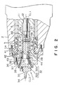
- a tool position correcting device 1 wherein a spindle 5 is supported for rotation in main bearings 3 on a spindle stock 2 of a machine tool, and a driven pulley 6 is mounted on the back end of the spindle 5. Belts 9 are extended between the driven pulley 6 and a drive pulley 8 mounted on the output shaft of a motor 7.
- the spindle 5 is provided with an axial central bore 11 extending along the axis CL1 (Fig. 2) of rotation of the spindle 5 and having opposite open ends.
- a draw bar 12 is axially movably inserted in the central bore 11 so that the front end portion thereof lies in an enlarged front section 11a (Fig. 2) of the central bore 11.
- the draw bar 12 is supported rotatably at its back end in bearings on a moving member 14.
- a rod 16 has an upper end fixed to the moving member 16, and a lower end rotatably supporting a guide roller 17.
- the guide roller 17 is in a guide groove 19 formed in a stand 18 to restrain the moving member 14 from turning.
- An internally threaded block 21 is fixedly mounted on the moving member 14, and a screw shaft 23 coupled with the output shaft of a motor 22 supported on the stand 18 is screwed in the internally threaded block 21.
- the moving member 14 is advanced and retracted in a range between a position indicated by solid lines and a position indicated by imaginary lines in Fig. 1 to move the draw bar 12 axially in opposite directions relative to the spindle 5 in the central bore 11 of the spindle 5.
- the spindle stock 2, the stand 18 and the motor 7 are fixedly mounted on a slide 25, which is moved axially in opposite directions by a ball-and-screw mechanism 50.
- a slide cam member 27 is fitted for axial movement in the enlarged section 11a of the central bore 11, and fitted on and fastened with a screw 12a to the front end portion of the draw bar 12.
- the slide cam member 27 is restrained from turning relative to the spindle 5 by a machine key 28 inserted between the slide cam member 27 and the spindle 5.
- the slide cam member 27 is provided with a holder support hole 31 having an eccentric center axis CL2 displaced by a small eccentricity from the axis CL1 of rotation of the spindle 5.
- a tool holder 32 i.e., an eccentric rotary member, has a back portion 32a rotatably fitted in the holder support hole 31, and a front portion 32b tapered backward.
- An arbor 35 is fastened to the front end surface of the tapered front portion 32b with screws, and a tool 34 is attached to the free end of the arbor 35.
- An adapter 36 is fastened with screws to the front end surface of the spindle 5 with its center axis in alignment with the eccentric center axis CL2 of the holder support hole 31.
- the adapter 36 is provided with a hole 37 tapered backward and conforming with the tapered front portion 32b of the tool holder 32.
- Steel balls 38 are interposed between the tapered front portion 32b and the surface of the tapered hole 37.
- the steel balls 38 are retained rotatably at equal angular intervals on the front and the back end of a highly rigid retainer 39.
- a stop ring 41 is fixed to the outer surface of the back portion 32a, and front and back collars 42 are mounted on the back portion 32a between the stop ring 41 and the back end surface of the adapter 36.
- a spring 44 is extended between the front and the back collar 42 to bias the tool holder 32 backward.
- a thrust bearing 43 is interposed between the front collar 42 and the back end surface of the adapter 36. The spring 44 is designed so that the resilience thereof is sufficient to hold the tool holder 32 firmly on the spindle 5 during heavy machining.
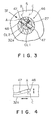
- cam slots 47 are formed at diametrically opposite positions, respectively, in the slide cam member 27.
- the opposite ends of a pin 48 fixed to the back end of the back portion 32a of the tool holder 32 are received in the cam slots 47, respectively.
- the cam slots 47 are designed to turn the pin 48 about the eccentric axis CL2 between a retracting position A and a limit position C when the slide cam member 27 is driven via the moving member 14 by the motor 22 for axial movement between a front position and a back position.
- the cutting edge of the tool 34 is retracted to the backmost position when the pin 48 is turned to the retracting position A .
- the pin 48 is located at a datum position B to locate the cutting edge of the tool 34 at a zero point before starting a machining operation.
- the operation of the tool position correcting device 1 will be described hereinafter.
- the arbor 35 holding a desired tool 34 is fastened to the tool holder 32, and the motor 22 is actuated to move the moving member 14 to locate the pin 48 at the datum position B for zeroing.
- the tool holder 32 is turned to be adjusted to an eccentric position where the cutting edge of the tool 34 is located at a position corresponding to a specified dimension of a work.
- the machine tool is started to machine the work.
- the motor 22 is actuated to shift the moving member 14 to the front limit position to cause the pin 48 to be turned to the retracting position A . Consequently, the tool 34 is retracted to separate the cutting edge thereof from the work.
- the slide 25 is driven for return travel by the ball-and-screw mechanism 50.
- the machined surface of the work will not be damaged with the tool 34 when the slide is driven for return travel because the tool 34 has been retracted.
- the dimension of the machined portion of the work is measured every time the machining cycle is completed and, when the measured dimension deviates beyond an allowable range due to the abrasion of the tool 34, a driving signal corresponding to a necessary correction is given to the motor 22 to retract the moving member 14 accordingly to turn the pin 48 toward the limit position C so that the position of the cutting edge of the tool 34 is corrected.
- the tapered front portion 32b of the tool holder 32 is held on the steel balls 38 in the tapered hole 37 of the adapter 36. Therefore, the tool holder 32 can be turned by a comparatively small torque when correcting the position of the cutting edge of the tool 34 and hence the motor 22 for axially moving the draw bar 12 may be of a comparatively small output capacity, the tool holder 32 can be held by an increased holding force on the spindle 5 during machining operation, and hence the tool position correcting device 1 is capable of firmly holding a tool during heavy machining.
- the agency of the spring further enhances the holding force for holding the tool holder 32 on the spindle 5.
Applications Claiming Priority (3)
| Application Number | Priority Date | Filing Date | Title |
|---|---|---|---|
| JP90399/95 | 1995-03-22 | ||
| JP9039995 | 1995-03-22 | ||
| JP7090399A JP3033086B2 (ja) | 1995-03-22 | 1995-03-22 | 刃具補正装置 |
Publications (2)
| Publication Number | Publication Date |
|---|---|
| EP0733426A1 true EP0733426A1 (de) | 1996-09-25 |
| EP0733426B1 EP0733426B1 (de) | 2001-12-12 |
Family
ID=13997514
Family Applications (1)
| Application Number | Title | Priority Date | Filing Date |
|---|---|---|---|
| EP96301849A Expired - Lifetime EP0733426B1 (de) | 1995-03-22 | 1996-03-19 | Werkzeugpositionskorrigiervorrichtung |
Country Status (7)
| Country | Link |
|---|---|
| US (1) | US5957632A (de) |
| EP (1) | EP0733426B1 (de) |
| JP (1) | JP3033086B2 (de) |
| KR (1) | KR960033648A (de) |
| CN (1) | CN1067310C (de) |
| DE (1) | DE69617777T2 (de) |
| TW (1) | TW390244U (de) |
Cited By (1)
| Publication number | Priority date | Publication date | Assignee | Title |
|---|---|---|---|---|
| CN110968035A (zh) * | 2018-10-01 | 2020-04-07 | 日本电产株式会社 | 校正系统、机床以及校正方法 |
Families Citing this family (9)
| Publication number | Priority date | Publication date | Assignee | Title |
|---|---|---|---|---|
| DE19859051A1 (de) * | 1998-12-22 | 2000-07-13 | Mapal Fab Praezision | Werkzeug und Verfahren zur spanabtragenden Bearbeitung eines Werkstücks |
| KR100343114B1 (ko) * | 2000-01-29 | 2002-07-05 | 박병철 | 공작기계의 스핀들 테이퍼부 보정방법 및 그 장치 |
| DE102005042718A1 (de) * | 2005-09-02 | 2007-03-08 | MAPAL Fabrik für Präzisionswerkzeuge Dr. Kress KG | Werkzeug zur spanenden Bearbeitung von Werkstückoberflächen |
| DE102008040379A1 (de) * | 2008-07-14 | 2010-01-21 | Robert Bosch Gmbh | Einrichtung zum Kalibrieren von Werkzeugmaschinen |
| JP5115753B2 (ja) * | 2009-04-16 | 2013-01-09 | エヌティーエンジニアリング株式会社 | 位置補正機能付き作業機械 |
| JP5120665B2 (ja) * | 2009-06-17 | 2013-01-16 | エヌティーエンジニアリング株式会社 | 位置補正機能付き作業機械 |
| JP5721424B2 (ja) | 2010-12-24 | 2015-05-20 | 三菱重工業株式会社 | 横型工作機械 |
| TWI423865B (zh) * | 2011-06-03 | 2014-01-21 | Sparking Power Technology Co Ltd | Component transfer device with floating guide mechanism |
| CN102820246B (zh) * | 2011-06-09 | 2014-10-22 | 承澔科技股份有限公司 | 具有浮动导正机构的元件移载装置 |
Citations (7)
| Publication number | Priority date | Publication date | Assignee | Title |
|---|---|---|---|---|
| US3254548A (en) * | 1964-04-13 | 1966-06-07 | Briney Mfg Co | Boring quill |
| US3640633A (en) * | 1969-08-28 | 1972-02-08 | Richard C Gersch | Adjustable boring quill assembly |
| DE2054165A1 (de) * | 1970-11-04 | 1972-05-10 | Cross Europa Werk Gmbh | Exzenterspindelstock |
| US3731562A (en) * | 1971-04-05 | 1973-05-08 | Bokum Tool Co Inc | Recessing tool |
| US3884590A (en) * | 1974-05-22 | 1975-05-20 | Lamb Co F Jos | Adjustable dual tool boring bar |
| DE3014334A1 (de) * | 1980-04-15 | 1981-10-22 | Coromant Engineering GmbH Gesellschaft zur Projektierung von Industrieanlagen, 6941 Laudenbach | Bohreinheit |
| DE4021090A1 (de) * | 1989-07-04 | 1991-01-17 | Fuji Bellows Co Ltd | Bearbeitungsvorrichtung mit mitteln zur aenderung der radialen position von schneidwerkzeugen |
Family Cites Families (5)
| Publication number | Priority date | Publication date | Assignee | Title |
|---|---|---|---|---|
| US2643556A (en) * | 1950-03-15 | 1953-06-30 | Jr Ottis R Briney | Boring tool |
| US2558815A (en) * | 1950-03-15 | 1951-07-03 | Jr Ottis R Briney | Boring tool structure |
| DE3720630A1 (de) * | 1987-06-23 | 1989-01-05 | Walter Bauer | Werkzeug zur umfangsschneidenden bearbeitung von werkstuecken, insbesondere zum bohren |
| DE4201715A1 (de) * | 1992-01-23 | 1993-07-29 | Peter Baumgaertner | Vorrichtung zur herstellung von praezisionsbohrungen |
| US5322304A (en) * | 1993-04-15 | 1994-06-21 | Wayne State University | Tool holder-spindle connection |
-
1995
- 1995-03-22 JP JP7090399A patent/JP3033086B2/ja not_active Expired - Fee Related
- 1995-12-04 TW TW088206573U patent/TW390244U/zh not_active IP Right Cessation
-
1996
- 1996-03-18 US US08/617,179 patent/US5957632A/en not_active Expired - Fee Related
- 1996-03-19 DE DE69617777T patent/DE69617777T2/de not_active Expired - Fee Related
- 1996-03-19 EP EP96301849A patent/EP0733426B1/de not_active Expired - Lifetime
- 1996-03-20 KR KR1019960007592A patent/KR960033648A/ko not_active Application Discontinuation
- 1996-03-22 CN CN96107355A patent/CN1067310C/zh not_active Expired - Fee Related
Patent Citations (7)
| Publication number | Priority date | Publication date | Assignee | Title |
|---|---|---|---|---|
| US3254548A (en) * | 1964-04-13 | 1966-06-07 | Briney Mfg Co | Boring quill |
| US3640633A (en) * | 1969-08-28 | 1972-02-08 | Richard C Gersch | Adjustable boring quill assembly |
| DE2054165A1 (de) * | 1970-11-04 | 1972-05-10 | Cross Europa Werk Gmbh | Exzenterspindelstock |
| US3731562A (en) * | 1971-04-05 | 1973-05-08 | Bokum Tool Co Inc | Recessing tool |
| US3884590A (en) * | 1974-05-22 | 1975-05-20 | Lamb Co F Jos | Adjustable dual tool boring bar |
| DE3014334A1 (de) * | 1980-04-15 | 1981-10-22 | Coromant Engineering GmbH Gesellschaft zur Projektierung von Industrieanlagen, 6941 Laudenbach | Bohreinheit |
| DE4021090A1 (de) * | 1989-07-04 | 1991-01-17 | Fuji Bellows Co Ltd | Bearbeitungsvorrichtung mit mitteln zur aenderung der radialen position von schneidwerkzeugen |
Cited By (1)
| Publication number | Priority date | Publication date | Assignee | Title |
|---|---|---|---|---|
| CN110968035A (zh) * | 2018-10-01 | 2020-04-07 | 日本电产株式会社 | 校正系统、机床以及校正方法 |
Also Published As
| Publication number | Publication date |
|---|---|
| TW390244U (en) | 2000-05-11 |
| JP3033086B2 (ja) | 2000-04-17 |
| US5957632A (en) | 1999-09-28 |
| EP0733426B1 (de) | 2001-12-12 |
| CN1067310C (zh) | 2001-06-20 |
| JPH08257811A (ja) | 1996-10-08 |
| KR960033648A (ko) | 1996-10-22 |
| DE69617777D1 (de) | 2002-01-24 |
| DE69617777T2 (de) | 2002-09-05 |
| CN1142996A (zh) | 1997-02-19 |
Similar Documents
| Publication | Publication Date | Title |
|---|---|---|
| JPS6135365Y2 (de) | ||
| US7024740B2 (en) | Rotating table apparatus | |
| US6726544B2 (en) | Method and apparatus for superfinishing tapered roller bearing | |
| US5957632A (en) | Tool position correcting device | |
| US20030102139A1 (en) | Tool, a machine, and a method for orbitally drilling an orifice | |
| US5030042A (en) | Machining apparatus having means for changing radial position of cutting tools | |
| US4845895A (en) | Internal grinding machine | |
| US4627773A (en) | Right angle spindle for machine tools | |
| US4047418A (en) | Combined drawing and straightening machine for metallic tubes or rods | |
| US4096771A (en) | Adjustable and floating boring bar stabilizer | |
| US4776248A (en) | Machine for cutting pipe, tubing or the like with cutter plane adjustment | |
| CA1084270A (en) | Orbiting cutter tangential machining tool | |
| US3334445A (en) | Grinding machine | |
| US4157635A (en) | Grinding machine for grinding a helical groove in a workpiece of tapering axial section | |
| US4605346A (en) | Tool wear compensator | |
| US4109420A (en) | Grinding machine, particularly for rollers of rolling element bearings | |
| US3654826A (en) | Adjustable tool block assembly | |
| JP2002137152A (ja) | 加工装置および加工方法 | |
| DE3226244A1 (de) | Verfahren und einrichtung zum ausgleich des werkzeugverschleisses bei einer bohrstange | |
| US4034647A (en) | Support for milling cutter | |
| JPH07242B2 (ja) | 回転長尺材の送り装置 | |
| US5619895A (en) | Tailstock for a lathe providing hydraulic axial length compensation | |
| KR900008002Y1 (ko) | 원판형 자동 조심(調心) 센터 | |
| RU1814986C (ru) | Расточна головка | |
| JP2783052B2 (ja) | 工具ホルダ |
Legal Events
| Date | Code | Title | Description |
|---|---|---|---|
| PUAI | Public reference made under article 153(3) epc to a published international application that has entered the european phase |
Free format text: ORIGINAL CODE: 0009012 |
|
| 17P | Request for examination filed |
Effective date: 19960401 |
|
| AK | Designated contracting states |
Kind code of ref document: A1 Designated state(s): DE FR GB IT |
|
| 17Q | First examination report despatched |
Effective date: 19981030 |
|
| GRAG | Despatch of communication of intention to grant |
Free format text: ORIGINAL CODE: EPIDOS AGRA |
|
| GRAG | Despatch of communication of intention to grant |
Free format text: ORIGINAL CODE: EPIDOS AGRA |
|
| GRAH | Despatch of communication of intention to grant a patent |
Free format text: ORIGINAL CODE: EPIDOS IGRA |
|
| GRAH | Despatch of communication of intention to grant a patent |
Free format text: ORIGINAL CODE: EPIDOS IGRA |
|
| GRAA | (expected) grant |
Free format text: ORIGINAL CODE: 0009210 |
|
| AK | Designated contracting states |
Kind code of ref document: B1 Designated state(s): DE FR GB IT |
|
| REG | Reference to a national code |
Ref country code: GB Ref legal event code: IF02 |
|
| REF | Corresponds to: |
Ref document number: 69617777 Country of ref document: DE Date of ref document: 20020124 |
|
| PLBE | No opposition filed within time limit |
Free format text: ORIGINAL CODE: 0009261 |
|
| STAA | Information on the status of an ep patent application or granted ep patent |
Free format text: STATUS: NO OPPOSITION FILED WITHIN TIME LIMIT |
|
| 26N | No opposition filed | ||
| PGFP | Annual fee paid to national office [announced via postgrant information from national office to epo] |
Ref country code: FR Payment date: 20060227 Year of fee payment: 11 |
|
| PGFP | Annual fee paid to national office [announced via postgrant information from national office to epo] |
Ref country code: GB Payment date: 20060315 Year of fee payment: 11 |
|
| PGFP | Annual fee paid to national office [announced via postgrant information from national office to epo] |
Ref country code: DE Payment date: 20060316 Year of fee payment: 11 |
|
| PGFP | Annual fee paid to national office [announced via postgrant information from national office to epo] |
Ref country code: IT Payment date: 20060331 Year of fee payment: 11 |
|
| GBPC | Gb: european patent ceased through non-payment of renewal fee |
Effective date: 20070319 |
|
| REG | Reference to a national code |
Ref country code: FR Ref legal event code: ST Effective date: 20071130 |
|
| PG25 | Lapsed in a contracting state [announced via postgrant information from national office to epo] |
Ref country code: DE Free format text: LAPSE BECAUSE OF NON-PAYMENT OF DUE FEES Effective date: 20071002 |
|
| PG25 | Lapsed in a contracting state [announced via postgrant information from national office to epo] |
Ref country code: GB Free format text: LAPSE BECAUSE OF NON-PAYMENT OF DUE FEES Effective date: 20070319 |
|
| PG25 | Lapsed in a contracting state [announced via postgrant information from national office to epo] |
Ref country code: FR Free format text: LAPSE BECAUSE OF NON-PAYMENT OF DUE FEES Effective date: 20070402 |
|
| PG25 | Lapsed in a contracting state [announced via postgrant information from national office to epo] |
Ref country code: IT Free format text: LAPSE BECAUSE OF NON-PAYMENT OF DUE FEES Effective date: 20070319 |