EP0733416A1 - Method and device for the manufacture of reinforcing grids - Google Patents
Method and device for the manufacture of reinforcing grids Download PDFInfo
- Publication number
- EP0733416A1 EP0733416A1 EP96890033A EP96890033A EP0733416A1 EP 0733416 A1 EP0733416 A1 EP 0733416A1 EP 96890033 A EP96890033 A EP 96890033A EP 96890033 A EP96890033 A EP 96890033A EP 0733416 A1 EP0733416 A1 EP 0733416A1
- Authority
- EP
- European Patent Office
- Prior art keywords
- longitudinal
- welding machine
- bars
- feed
- crossbar
- Prior art date
- Legal status (The legal status is an assumption and is not a legal conclusion. Google has not performed a legal analysis and makes no representation as to the accuracy of the status listed.)
- Granted
Links
Images


Classifications
-
- B—PERFORMING OPERATIONS; TRANSPORTING
- B21—MECHANICAL METAL-WORKING WITHOUT ESSENTIALLY REMOVING MATERIAL; PUNCHING METAL
- B21F—WORKING OR PROCESSING OF METAL WIRE
- B21F27/00—Making wire network, i.e. wire nets
- B21F27/08—Making wire network, i.e. wire nets with additional connecting elements or material at crossings
- B21F27/10—Making wire network, i.e. wire nets with additional connecting elements or material at crossings with soldered or welded crossings
-
- B—PERFORMING OPERATIONS; TRANSPORTING
- B21—MECHANICAL METAL-WORKING WITHOUT ESSENTIALLY REMOVING MATERIAL; PUNCHING METAL
- B21F—WORKING OR PROCESSING OF METAL WIRE
- B21F27/00—Making wire network, i.e. wire nets
- B21F27/12—Making special types or portions of network by methods or means specially adapted therefor
- B21F27/20—Making special types or portions of network by methods or means specially adapted therefor of plaster-carrying network
Definitions
- the invention relates to a method for producing reinforcement meshes, which consist of longitudinal and cross bars welded to one another, after which the longitudinal bars, which are aligned and cut in a preparation step, are placed on a feed device and in the longitudinal direction in the mat-appropriate position, taking into account any mesh recesses or the like guided step by step from crossbar position to crossbar position by a welding machine and in each case welded to the crossbars belonging to these crossbar positions, also directed in a preparatory step, cut and positioned to suit the mat, taking into account any mat recesses or the like, and to a device for carrying out this method.
- the invention is therefore based on the object of eliminating these deficiencies and of specifying a method of the type described at the outset which permits relatively quick and rational mat production.
- a space-saving and low-cost device for carrying out this method is to be created.
- the invention solves this problem by first placing only the longitudinal bars reaching the foremost crossbar position (s) in the feed direction and then the rest of the series, as they reach the successive crossbar positions with their front ends.
- the longitudinal and cross bars can consist of different diameters and in the course of the mat production in a preparation step from corresponding wire reels, be straightened and cut, the rods also with spacers u.
- the like. Can be equipped. The individual process steps, the positioning and alignment of the bars, the choice of materials and the like. The like. Can be carried out automatically by means of suitable control programs, so that any individually designed mats or different standard mats can be produced one after the other without interruption. Due to the possibility of an immediately successive manufacture of the individual reinforcement meshes, the space requirements for the manufacture remain within manageable limits and the feed device does not have to be designed in the feed direction in front of the welding machine to be at least two full mesh lengths as in the known systems.
- a particularly useful device for carrying out the method according to the invention has a feed device assigned to a welding machine, a longitudinal bar magazine and a cross bar magazine and laying devices for the longitudinal and transverse bars and is characterized in that the feed device in front of the welding machine also has a feed carriage which can be moved back and forth in the feed direction a plurality of side-by-side mounting profiles for inserting the longitudinal rods and behind the welding machine includes a towing carriage movable in the pull-off direction with tongs laterally offset from the mounting profiles.
- the longitudinal bars are inserted into the receiving profiles of the feed carriage in a mat-appropriate manner and brought into the welding machine by advancing the feed carriage.
- the tongs of the tow truck approached to the welding machine can grip the welded crossbars and the longitudinal bars held together by the crossbars can be pulled forward with the tow truck and welded to the crossbars one after the other.
- the feed carriage stands still and the longitudinal bars are pulled out of the receiving profiles.
- the front ends of the longitudinal bars can be pressed against the raised straightening swords and aligned with them in a simple manner. After aligning and lowering the sabers, the feed carriage brings the longitudinal bars with their front ends aligned into the welding machine.
- the feed carriages are moved back relative to these longitudinal bars, the new longitudinal bars are placed in the correct position, the feed carriage moves the new longitudinal bars relative to the clamped longitudinal rods against the again raised swords, so that the new longitudinal rods are also aligned, and after completion of the respective welding step, the feed carriage with the new longitudinal rods is fed together with the other longitudinal rods to the welding machine during the next feed step, where then the welded-on crossbars
- the new longitudinal bars are connected to the already installed longitudinal bars. It is of course also possible to arrange the longitudinal bars with different overhangs with respect to the foremost cross bar and then to adjust them step by step.
- the welding machine is assigned a crossbar magazine bridging the feed device, which has a plurality of receiving compartments for the positioned receiving of crossbars, wherein a straightening device can preferably be assigned to the receiving compartments.
- a cross bar magazine which is designed as a flap magazine or chain magazine or the like
- the cross bars are already brought into the position of the welding machine in a position suitable for the mat and can be welded onto the longitudinal bars in a rational manner.
- a straightening device for example a straightening magnet, allows the positioned transverse support to be checked within the receiving compartments, so that perfect mat production is ensured.
- the cross bars which optionally belong to one another along a common cross bar position, are also placed together on the longitudinal bars and welded to them, the respective crossbar position depends on the longitudinal bar feed and can therefore be selected as required.
- the mechanical outlay can be significantly reduced and a very flexible welding device can be achieved.
- the individual welding heads are positioned transversely as required, so that separate welding units are no longer required for all mounting profiles of the feed carriage.
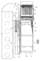
- a device 1 for the automatic production of reinforcement meshes M comprises a straightening and cutting machine 2 for the preparatory processing of reinforcement wires into longitudinal and transverse bars, a transverse rod magazine 3 and a longitudinal rod magazine 4 and a welding machine 5 with a suitable feed device 6.
- the straightening and cutting machine 2 is equipped with a plurality of wire reels 21 for the different wire diameters and, with straightening and cutting devices (not shown further), allows the selected wires to be aligned and cut, which are then distributed via a distributor 22 as longitudinal bars L into the longitudinal bar magazine 4 or as transverse bars Q are placed in the cross bar magazine 3, where they are waiting for further processing.
- the longitudinal rod magazine 4 extends parallel to the feed device 6 and is a laying robot 41 assigned.
- the cross bar magazine 3 is divided into a longitudinal buffer store 31 and a cross-directional flap magazine 32 bridging the feed device 6, the flap magazine 32 having a plurality of receiving compartments 33 arranged in series, which, depending on the progress of work, from the buffer store 31 via a suitable laying device 34 with the prepared cross bars in the correct position become.
- the welding machine 5 has individual transverse adjustable welding heads 51 for welding the longitudinal and transverse bars, the welding heads being positioned according to the welding points.
- the feed device 6 is composed of a feed carriage 61, which can be moved back and forth in the feed direction in front of the welding machine 5 on a suitable frame 62 and has a multiplicity of receiving profiles 63 arranged next to one another for inserting the longitudinal bars L, and also of a towing carriage 64 arranged downstream of the welding machine 5 compared to the receiving profiles 63 laterally offset tongs 65, which can be moved in the pull-off direction and can penetrate with its tongs 65 into the area of the welding machine 5.
- a straightening station 7 with elevating swords 71 is provided for longitudinally aligning the longitudinal bars L placed on the feed carriage 61, and a displacement device 72 for positioning the crossbar is also assigned to the flap magazine 32 of the crossbar magazine 3.
- the required transverse and longitudinal bars are prepared in preparation steps in the wire straightening and cutting machine 2 and the Longitudinal or cross bar magazines 3, 4 fed.
- the cross bars Q are lined up in the flap magazine 32 in the order in which they are processed in a position and size that is appropriate for the mat, the excess cross bars Q not finding space in the flap magazine initially remaining in the buffer store 31.
- the longitudinal bars L are removed from the longitudinal bar magazine 4 via the laying robot 41 and inserted into the receiving profiles 63 of the feed carriage 61 in a manner suitable for the mat, only the longitudinal bars which protrude into or to a foremost transverse bar position being inserted first.
- the feed carriage 61 is in its retracted initial position and receives the longitudinal bars with a suitable overhang relative to the receiving profiles 63. Now the feed carriage 61 is advanced by means of its feed drive 66 against the straightening station 7 with its raised swords 71 so that the longitudinal bars pressed against the swords 71 are positioned exactly. After positioning, the guide blades 71 are lowered and the feed carriage 61 introduces the longitudinal bars into the welding machine 5 by further advancing.
- the longitudinal bars are now welded via the appropriately positioned welding heads 51 to the cross bar or bars assigned to the first cross bar position, which are located in the first folding compartment of the folding magazine 32 and are fed to the welding machine 5 by opening this compartment. If the first foldable compartment is empty, the subsequent transverse rods are gradually conveyed by folding over the following foldable compartments 33 and prepared for the welding process.
- the towing vehicle 64 is advanced and the tongs 65 are suspended in the welded crossbar, which is possible without difficulty due to the offset of the tongs relative to the receiving profiles.
- the longitudinal bars can be pulled off the feed wagon 61 and released until the next one selectable and variable crossbar position are introduced into the welding machine 5.
- the towing vehicle 64 stops, the next cross bar or bars are transferred to the welding machine 5 and welded on.
- the corresponding cross bars are now welded onto the longitudinal bars step by step.
- the feed carriage 61 moves back to its starting position relative to the longitudinal bars clamped by the tongs 65, so that, similar to the first longitudinal bars, an ancestor against the straightening station 7 then also enables the new longitudinal bars to be aligned and then the longitudinal rods are properly retracted into the welding machine.
- a connection between the already welded rods and the new longitudinal rods is then made here with the next transverse rod, so that the new longitudinal rods are also pulled along via the towing vehicle 64.
- the required longitudinal bars L and cross bars Q are first prepared and stored (Fig. 3a), then Longitudinal bars La placed on the feed device 6, which reach the first crossbar position P1 with their front ends (Fig. 3b), so that after the welding of the first crossbar Qa by means of the welding machine 5, the further mat feed can take place via the tongs.
- the various cross bars Q which are cut and positioned according to the shape of the mat, are welded on until position P2 is reached in the welding machine, whereupon new, shorter longitudinal bars Lb are inserted.
- the longitudinal bars Lb are placed and aligned so that in the next feed step all the longitudinal bars La, Lb reaching the position P3 enter the welding machine (FIG. 3c).
- the cross bar Qc is welded on and thus all existing longitudinal bars La, Lb are connected to each other, which means that a further advance is again only possible using the tongs.
- the remaining cross bars Q are finally welded on step by step until the mat M is finished (FIG. 3d).
Landscapes
- Engineering & Computer Science (AREA)
- Mechanical Engineering (AREA)
- Wire Processing (AREA)
- Manufacturing Of Tubular Articles Or Embedded Moulded Articles (AREA)
- Reinforcement Elements For Buildings (AREA)
Abstract
Description
Die Erfindung bezieht sich auf ein Verfahren zum Herstellen von Bewehrungsmatten, die aus miteinander verschweißten Längs- und Querstäben bestehen, nach dem die in einem Vorbereitungsschritt gerichteten und zugeschnittenen Längsstäbe in mattengerechter Position unter Berücksichtigung etwaiger Mattenaussparungen od. dgl. auf eine Vorschubeinrichtung aufgelegt und in Längsrichtung schrittweise von Querstabposition zu Querstabposition durch eine Schweißmaschine geführt und dabei jeweils mit den diesen Querstabpositionen zugehörenden, ebenfalls in einem Vorbereitungsschritt gerichteten, zugeschnittenen und mattengerecht unter Berücksichtigung etwaiger Mattenaussparungen od. dgl. positionierten Querstäben verschweißt werden, sowie auf eine Vorrichtung zum Durchführen dieses Verfahrens.The invention relates to a method for producing reinforcement meshes, which consist of longitudinal and cross bars welded to one another, after which the longitudinal bars, which are aligned and cut in a preparation step, are placed on a feed device and in the longitudinal direction in the mat-appropriate position, taking into account any mesh recesses or the like guided step by step from crossbar position to crossbar position by a welding machine and in each case welded to the crossbars belonging to these crossbar positions, also directed in a preparatory step, cut and positioned to suit the mat, taking into account any mat recesses or the like, and to a device for carrying out this method.
Bisher werden zur Herstellung von massiven Betonfertigteilelementen mit Aussparungen für Türen und/oder Fenstern, Randausnehmungen, Abschrägungen u. dgl. meist Standardmatten verwendet, die zur Anpassung an das herzustellende Element händisch mit einer Bolzenschere zurechtgeschnitten werden müssen, worauf geeignete Verstärkungseisen im Randbereich der Ausschnitte mittels Draht oder Schutzgasschweißung zu befestigen sind, was sehr arbeits- und zeitintensiv und wegen der größtenteils hohen Bewehrungsgewichte überaus mühsam und beschwerlich ist.So far, for the production of solid precast elements with cutouts for doors and / or windows, edge recesses, bevels and. Mostly standard mats are used, which have to be cut by hand with a pair of bolt cutters to adapt to the element to be manufactured, whereupon suitable reinforcing irons are to be fastened in the edge area of the cutouts using wire or inert gas welding, which is very labor-intensive and time-consuming and, due to the largely high reinforcement weights, extremely tedious and is arduous.
Um diesen Fertigungsprozeß zu automatisieren, wurde gemäß der EP-A 0 482 842 bereits vorgeschlagen, die Bewehrungsmatten von vornherein in ihren Abmessungen und Aussparungen auf den jeweiligen Verwendungszweck abzustimmen, wobei die Längsstäbe entsprechend der Endgestalt der Bewehrungsmatten zugeschnitten und positioniert auf eine Vorschubeinrichtung aufgelegt und in einer Schweißmaschine mit den ebenfalls mattengerecht zugeschnittenen und positionierten Querstäben verschweißt werden. Dadurch ist es möglich, in einem maschinellen Herstellungsverfahren Bewehrungsmatten unter Verwendung geeigneter Bewehrungseisen in der jeweils gewünschten Form herzustellen und ein anschließendes händisches Weiterbearbeiten durch Zuschneiden u. dgl. zu vermeiden. Nach dem bekannten Verfahren werden allerdings vor dem Schweißen alle Längsstäbe einer Bewehrungsmatte in einem einheitlichen Verlegeschritt positioniert auf einer Palette od. dgl. der Vorschubeinrichtung aufgelegt und dann erst diese Palette durch die Schweißmaschine zum stückweisen Aufschweißen der Querstäbe hindurchgefördert, so daß sich nur recht geringe Fertigungskapazitäten erreichen lassen und sehr platzraubende Herstellungsanlagen notwendig sind.In order to automate this manufacturing process, it has already been proposed according to EP-A 0 482 842 to match the reinforcement mats in terms of their dimensions and recesses from the outset to the respective intended use, the longitudinal bars being cut and positioned according to the final shape of the reinforcement mats and placed on a feed device and in a welding machine with the cross bars, which are also cut and positioned to match the mat. This makes it possible to manufacture reinforcement mats in a mechanical manufacturing process using suitable reinforcement bars in the desired shape and subsequent manual processing by cutting u. To avoid. According to the known method, however, all longitudinal bars of a reinforcement mat are positioned in a uniform laying step on a pallet or the like before the welding, placed on the feed device, and only then is this pallet conveyed through the welding machine for piecewise welding of the cross bars, so that only very small production capacities are achieved can be achieved and very space-consuming manufacturing plants are necessary.
Der Erfindung liegt daher die Aufgabe zugrunde, diese Mängel zu beseitigen und ein Verfahren der eingangs geschilderten Art anzugeben, das ein verhältnismäßig rasches und rationelles Mattenfertigen erlaubt. Außerdem soll eine platzsparende und aufwandsarme Vorrichtung zur Durchführung dieses Verfahrens geschaffen werden.The invention is therefore based on the object of eliminating these deficiencies and of specifying a method of the type described at the outset which permits relatively quick and rational mat production. In addition, a space-saving and low-cost device for carrying out this method is to be created.
Die Erfindung löst diese Aufgabe dadurch, daß zuerst nur die in Vorschubrichtung die vorderste(n) Querstabposition(en) erreichenden Längsstäbe aufgelegt werden und dann die übrigen der Reihe nach, wie sie mit ihren Vorderenden die aufeinanderfolgenden Querstabpositionen erreichen. Durch diese einfache Maßnahme der auf die jeweiligen Querstabpositionen abgestimmten Längsstabauflage ist es möglich, den Schritt der Längsstabauflage und den Schritt der Querstabaufschweißung überlappend durchzuführen, da der oder die einer Querstabposition zugehörenden Querstäbe sofort aufgeschweißt werden können, sobald die zugehörenden Längsstäbe aufgelegt sind. Es kommt dabei in Abhängigkeit von der Mattengestalt schon während des Längsstabauflageschrittes zu einem Längsvorschub, so daß ein rationelles und beschleunigtes Mattenherstellen gewährleistet ist. Es lassen sich die verschiedensten Matten und Mattenformen herstellen, die Längs- und Querstäbe können aus unterschiedlichsten Durchmessern bestehen und im Zuge der Mattenherstellung in einem Vorbereitungsschritt von entsprechenden Drahthaspeln abgezogen, gerichtet und zugeschnitten werden, wobei die Stäbe auch gleich mit Abstandhaltern u. dgl. bestückbar sind. Die einzelnen Verfahrensschritte, das Positionieren und Ausrichten der Stäbe, die Materialwahl u. dgl. können mittels geeigneter Steuerprogramme automatisch durchgerührt werden, so daß sich beliebige individuell gestaltete Matten oder auch verschiedene Standardmatten ohne Unterbrechung hintereinander herstellen lassen. Durch die Möglichkeit einer unmittelbar aufeinanderfolgenden Fertigung der einzelnen Bewehrungsmatten bleiben die Platzansprüche für die Herstellung in überschaubaren Grenzen und die Vorschubeinrichtung muß nicht in Vorschubrichtung vor der Schweißmaschine zumindest auf zwei volle Mattenlängen wie bei den bekannten Anlagen ausgelegt sein.The invention solves this problem by first placing only the longitudinal bars reaching the foremost crossbar position (s) in the feed direction and then the rest of the series, as they reach the successive crossbar positions with their front ends. Through this simple measure of the matched to the respective crossbar positions Longitudinal bar support, it is possible to overlap the step of longitudinal bar support and the step of cross bar welding, since the cross bar or bars belonging to a cross bar position can be welded on as soon as the associated longitudinal bars are placed on. Depending on the shape of the mat, there is already a longitudinal feed during the longitudinal rod support step, so that efficient and accelerated mat production is ensured. It can produce a wide variety of mats and mat shapes, the longitudinal and cross bars can consist of different diameters and in the course of the mat production in a preparation step from corresponding wire reels, be straightened and cut, the rods also with spacers u. The like. Can be equipped. The individual process steps, the positioning and alignment of the bars, the choice of materials and the like. The like. Can be carried out automatically by means of suitable control programs, so that any individually designed mats or different standard mats can be produced one after the other without interruption. Due to the possibility of an immediately successive manufacture of the individual reinforcement meshes, the space requirements for the manufacture remain within manageable limits and the feed device does not have to be designed in the feed direction in front of the welding machine to be at least two full mesh lengths as in the known systems.
Werden die übrigen Längsstäbe erst dann aufgelegt, wenn jeweils die ihren Vorderenden vorgeordnete Querstabposition in die Schweißmaschine gelangt, lassen sich Platzbedarf und Arbeitsgeschwindigkeit optimieren, da die Längsstäbe erst unmittelbar vor dem eigentlichen Schweißvorgang zum Verschweißen mit den Querstäben aufgebracht werden und es weder zu langen Vorschubwegen noch zu langen Vorschubzeiten kommt.If the other longitudinal bars are only put on when the crossbar position upstream of their front ends reaches the welding machine, space requirements and working speed can be optimized, since the longitudinal bars are only applied for welding to the crossbars immediately before the actual welding process and neither too long feed paths nor leads to long feed times.
Eine besonders zweckmäßige Vorrichtung zum Durchführen des erfindungsgemäßen Verfahrens weist eine einer Schweißmaschine zugeordnete Vorschubeinrichtung, ein Längsstabmagazin und ein Querstabmagazin sowie Verlegeeinrichtungen für die Längs- und Querstäbe auf und ist dadurch gekennzeichnet, daß die Vorschubeinrichtung vor der Schweißmaschine einen in Vorschubrichtung hin- und herfahrbaren Vorschubwagen mit einer Vielzahl nebeneinandergereihter Aufnahmeprofile zum Einlegen der Längsstäbe und hinter der Schweißmaschine einen in Abzugsrichtung verfahrbaren Schleppwagen mit gegenüber den Aufnahmeprofilen seitlich versetzten Schleppzangen umfaßt. Die Längsstäbe werden mattengerecht in die Aufnahmeprofile des Vorschubwagens eingelegt und durch Vorfahren des Vorschubwagens in die Schweißmaschine eingebracht. Sobald hier der oder die entsprechenden Querstäbe aufgeschweißt sind, können die Schleppzangen des an die Schweißmaschine herangefahrenen Schleppwagens die aufgeschweißten Querstäbe ergreifen und die über die Querstäbe zusammengehaltenen Längsstäbe lassen sich mit dem Schleppwagen vorschubgemäß vorwärtsziehen und nacheinander mit den Querstäben verschweißen. Während dieses Vorwärtsziehens steht der Vorschubwagen still und die Längsstäbe werden aus den Aufnahmeprofilen herausgezogen. Damit wird mit zunehmendem Vorschubweg entsprechend Platz frei, um weitere Längsstäbe aufzulegen bzw. um ohne Unterbrechung gleich wieder mit der Auflage von Längsstäben einer neuen Matte beginnen zu können, wobei sogar durch ein querversetztes Auflegen der Längsstäbe zweier hintereinander herzustellender Matten ein platzgewinnendes Ineinandergreifen der Matten möglich wird.A particularly useful device for carrying out the method according to the invention has a feed device assigned to a welding machine, a longitudinal bar magazine and a cross bar magazine and laying devices for the longitudinal and transverse bars and is characterized in that the feed device in front of the welding machine also has a feed carriage which can be moved back and forth in the feed direction a plurality of side-by-side mounting profiles for inserting the longitudinal rods and behind the welding machine includes a towing carriage movable in the pull-off direction with tongs laterally offset from the mounting profiles. The longitudinal bars are inserted into the receiving profiles of the feed carriage in a mat-appropriate manner and brought into the welding machine by advancing the feed carriage. As soon as the corresponding crossbar (s) are welded on, the tongs of the tow truck approached to the welding machine can grip the welded crossbars and the longitudinal bars held together by the crossbars can be pulled forward with the tow truck and welded to the crossbars one after the other. During this forward pull, the feed carriage stands still and the longitudinal bars are pulled out of the receiving profiles. As the feed path increases, this frees up space to place further longitudinal bars or to be able to start laying longitudinal bars of a new mat without interruption, whereby even space-saving interlocking of the mats is possible by cross-laying the longitudinal bars of two mats to be produced one behind the other becomes.
Ist schweißmaschinenseitig vor dem Vorschubwagen eine Richtstation mit hochfahrbaren Richtschwertern vorgesehen, läßt sich auf einfache Weise beim Einlegen der Längsstäbe deren Vorderenden an die hochgefahrenen Richtschwerter andrücken und damit ausrichten. Nach dem Ausrichten und dem Absenken der Richtschwerter bringt dann der Vorschubwagen die Längsstäbe mit ihren ausgerichteten Vorderenden in die Schweißmaschine. Sind nach den ersten Längsstäben die übrigen Längsstäbe aufzulegen, wird während des Festhaltens der bereits aufgelegten Längsstäbe mit den an den aufgeschweißten Querstäben angesetzten Schleppzangen der Vorschubwagen relativ zu diesen Längsstäben zurückverfahren, die neuen Längsstäbe werden positionsgerecht aufgelegt, der Vorschubwagen fährt die neuen Längsstäbe relativ zu den festgeklemmten Längsstäben gegen die wiederum hochgefahrenen Richtschwerter, so daß auch die neuen Längsstäbe ausgerichtet werden, und nach Beendigung des jeweiligen Schweißschrittes wird während des nächsten Vorschubschrittes der Vorschubwagen mit den neuen Längsstäben zusammen mit den übrigen Längsstäben der Schweißmaschine zugeführt, wo dann über die aufgeschweißten Querstäbe die Verbindung der neuen Längsstäbe mit den bereits verlegten Längsstäben erfolgt. Dabei ist es selbstverständlich auch möglich, die Längsstäbe mit unterschiedlichen Überständen gegenüber dem jeweils vordersten Querstab anzuordnen und dann schrittweise zu justieren.If a straightening station with elevating swords is provided on the welding machine side in front of the feed carriage, the front ends of the longitudinal bars can be pressed against the raised straightening swords and aligned with them in a simple manner. After aligning and lowering the sabers, the feed carriage brings the longitudinal bars with their front ends aligned into the welding machine. If the remaining longitudinal bars are to be placed after the first longitudinal bars, while the already attached longitudinal bars are held in place with the tongs attached to the welded-on transverse bars, the feed carriages are moved back relative to these longitudinal bars, the new longitudinal bars are placed in the correct position, the feed carriage moves the new longitudinal bars relative to the clamped longitudinal rods against the again raised swords, so that the new longitudinal rods are also aligned, and after completion of the respective welding step, the feed carriage with the new longitudinal rods is fed together with the other longitudinal rods to the welding machine during the next feed step, where then the welded-on crossbars The new longitudinal bars are connected to the already installed longitudinal bars. It is of course also possible to arrange the longitudinal bars with different overhangs with respect to the foremost cross bar and then to adjust them step by step.
Günstig ist es weiters, wenn der Schweißmaschine ein die Vorschubeinrichtung überbrückendes Querstabmagazin zugeordnet ist, das mehrere Aufnahmefächer zur positionierten Aufnahme von Querstäben aufweist, wobei vorzugsweise den Aufnahmefächern eine Richteinrichtung zugeordnet sein kann. Durch ein solches Querstabmagazin, das als Klappenmagazin oder Kettenmagazin od. dgl. ausgeführt ist, werden die Querstäbe bereits in mattengerechter Position der Schweißmaschine zugebracht und können rationell auf die Längsstäbe aufgeschweißt werden. Eine Richteinrichtung, beispielsweise ein Richtmagnet, erlaubt die Kontrolle der positionierten Querstablage innerhalb der Aufnahmefächer, so daß ein einwandfreies Mattenherstellen gewährleistet ist. Die gegebenenfalls nebeneinander einer gemeinsamen Querstabposition zugehörenden Querstäbe werden auch gemeinsam auf die Längsstäbe aufgelegt und mit diesen verschweißt, wobei die jeweilige Querstabposition vom Längsstabvorschub abhängt und daher beliebig vorwählbar ist.It is also expedient if the welding machine is assigned a crossbar magazine bridging the feed device, which has a plurality of receiving compartments for the positioned receiving of crossbars, wherein a straightening device can preferably be assigned to the receiving compartments. By means of such a cross bar magazine, which is designed as a flap magazine or chain magazine or the like, the cross bars are already brought into the position of the welding machine in a position suitable for the mat and can be welded onto the longitudinal bars in a rational manner. A straightening device, for example a straightening magnet, allows the positioned transverse support to be checked within the receiving compartments, so that perfect mat production is ensured. The cross bars, which optionally belong to one another along a common cross bar position, are also placed together on the longitudinal bars and welded to them, the respective crossbar position depends on the longitudinal bar feed and can therefore be selected as required.
Weist die Schweißmaschine einzelne querverstellbare Schweißköpfe zum Verschweißen der Längs- und Querstäbe auf, läßt sich der maschinelle Aufwand wesentlich verringern und eine sehr flexible Schweißeinrichtung erreichen. Die einzelnen Schweißköpfe werden je nach Erfordernis querpositioniert, so daß nicht mehr für alle Aufnahmeprofile des Vorschubwagens eigene Schweißeinheiten erforderlich sind.If the welding machine has individual, cross-adjustable welding heads for welding the longitudinal and transverse bars, the mechanical outlay can be significantly reduced and a very flexible welding device can be achieved. The individual welding heads are positioned transversely as required, so that separate welding units are no longer required for all mounting profiles of the feed carriage.
In der Zeichnung ist der Erfindungsgegenstand rein schematisch veranschaulicht, und zwar zeigen
- Fig. 1 und 2
- eine erfindungsgemäße Vorrichtung zum Herstellen von Bewehrungsmatten in Draufsicht bzw. in teilgeschnittener Seitenansicht sowie
- Fig. 3 a, b, c und d
- das Prinzip der Mattenherstellung an Hand einzelner Verfahrensschritte.
- 1 and 2
- a device according to the invention for producing reinforcement mesh in plan view or in a partially sectioned side view and
- 3 a, b, c and d
- the principle of mat production using individual process steps.
Eine Vorrichtung 1 zum automatischen Herstellen von Bewehrungsmatten M umfaßt eine Richt- und Schneidemaschine 2 zur vorbereitenden Verarbeitung von Bewehrungsdrähten zu Längs- und Querstäben, ein Querstabmagazin 3 und ein Längsstabmagazin 4 sowie eine Schweißmaschine 5 mit geeigneter Vorschubeinrichtung 6.A device 1 for the automatic production of reinforcement meshes M comprises a straightening and
Die Richt- und Schneidemaschine 2 ist mit mehreren Drahthaspeln 21 für die verschiedenen Drahtdurchmesser ausgestattet und erlaubt mit nicht weiter dargestellten Richt- und Schneideinrichtungen das Ausrichten und Zuschneiden der gewählten Drähte, die dann über eine Verteileinrichtung 22 als Längsstäbe L in das Längsstabmagazin 4 oder als Querstäbe Q in das Querstabmagazin 3 eingebracht werden, wo sie auf die Weiterverarbeitung warten. Das Längsstabmagazin 4 erstreckt sich längsparallel zur Vorschubeinrichtung 6 und ihm ist ein Verlegeroboter 41 zugeordnet. Das Querstabmagazin 3 ist in einen längsgerichteten Pufferspeicher 31 und ein die Vorschubeinrichtung 6 überbrückendes, quergerichtetes Klappenmagazin 32 unterteilt, wobei das Klappenmagazin 32 mehrere hintereinandergereihte Aufnahmefächer 33 aufweist, die je nach Arbeitsfortschritt vom Pufferspeicher 31 über eine geeignete Verlegeeinrichtung 34 positionsrichtig mit den vorbereiteten Querstäben Q befüllt werden.The straightening and
Die Schweißmaschine 5 weist einzelne querverstellbare Schweißköpfe 51 zum Verschweißen der Längs- und Querstäbe auf, wobei die Schweißköpfe entsprechend den Schweißstellen positioniert werden.The
Die Vorschubeinrichtung 6 setzt sich aus einem Vorschubwagen 61, der in Vorschubrichtung vor der Schweißmaschine 5 auf einem geeigneten Gestell 62 hin- und herverfahrbar ist und eine Vielzahl nebeneinandergereihter Aufnahmeprofile 63 zum Einlegen der Längsstäbe L aufweist, sowie aus einem der Schweißmaschine 5 nachgeordneten Schleppwagen 64 mit gegenüber den Aufnahmeprofilen 63 seitenversetzten Schleppzangen 65, der in Abzugsrichtung verfahrbar ist und mit seinen Schleppzangen 65 bis in den Bereich der Schweißmaschine 5 vordringen kann, zusammen.The
Im schweißmaschinenseitigen Verfahrbereich des Vorschubwagens 61 ist eine Richtstation 7 mit hochfahrbaren Richtschwertern 71 zum Längsausrichten der auf den Vorschubwagen 61 aufgelegten Längsstäbe L vorgesehen und auch dem Klappenmagazin 32 des Querstabmagazins 3 ist eine Verschiebeeinrichtung 72 zur Querstabpositionierung zugeordnet.In the travel area of the
Zur Herstellung einer Bewehrungsmatte M werden die dazu erforderlichen Quer- und Längsstäbe in Vorbereitungsschritten in der Drahtricht- und Schneidemaschine 2 vorbereitet und den Längs- bzw. Querstabmagazinen 3, 4 zugefördert. Die Querstäbe Q werden im Klappenmagazin 32 in der Reihenfolge ihrer Verarbeitung in mattengerechter Position und Größe hintereinandergereiht, wobei die nicht im Klappenmagazin platzfindenden überzähligen Querstäbe Q vorerst im Pufferspeicher 31 bleiben. Nun werden über den Verlegeroboter 41 die Längsstäbe L aus dem Längsstabmagazin 4 entnommen und mattengerecht in die Aufnahmeprofile 63 des Vorschubwagens 61 eingelegt, wobei zuerst nur die Längsstäbe eingelegt werden, die bis in die oder eine vorderste Querstabposition vorragen. Der Vorschubwagen 61 befindet sich in seiner zurückgezogenen Ausgangsstellung und nimmt die Längsstäbe mit geeignetem Überstand gegenüber den Aufnahmeprofilen 63 auf. Nun wird der Vorschubwagen 61 mittels seines Vorschubantriebes 66 gegen die Richtstation 7 mit ihren hochgefahrenen Richtschwertern 71 vorgefahren, so daß die an die Richtschwerter 71 angedrückten Längsstäbe exakt positioniert werden. Nach dem Positionieren werden die Richtschwerter 71 abgesenkt und der Vorschubwagen 61 bringt durch weiteres Vorfahren die Längsstäbe in die Schweißmaschine 5 ein.To produce a reinforcement mat M, the required transverse and longitudinal bars are prepared in preparation steps in the wire straightening and
In der Schweißmaschine 5 werden nun die Längsstäbe über die entsprechend positionierten Schweißköpfe 51 mit dem oder den der ersten Querstabposition zugeordneten Querstab bzw. Querstäben, die in dem ersten Klappfach des Klappmagazins 32 liegen und durch Öffnen dieses Faches der Schweißmaschine 5 zugeführt werden, verschweißt. Ist das erste Klappfach leer, werden durch Umklappen der folgenden Klappfächer 33 die nachfolgenden Querstäbe schrittweise nachgefördert und für den Schweißvorgang vorbereitet. Nach dem Verschweißen des ersten Querstabes wird der Schleppwagen 64 vorgefahren und die Schleppzangen 65 im angeschweißten Querstab eingehängt, was ohne Schwierigkeiten durch den Versatz der Schleppzangen gegenüber den Aufnahmeprofilen möglich ist. Nun können durch ein Zurückfahren des Schleppwagens 64 die Längsstäbe vom Vorschubwagen 61 abgezogen und bis zur nächsten an sich frei wählbaren und variierbaren Querstabposition in die Schweißmaschine 5 eingebracht werden. Der Schleppwagen 64 stoppt, der oder die nächsten Querstäbe werden an die Schweißmaschine 5 übergeben und angeschweißt. In ähnlicher Folge werden nun Schritt für Schritt die entsprechenden Querstäbe auf die Längsstäbe aufgeschweißt.In the
Sind kürzere Längsstäbe neu aufzulegen, fährt der Vorschubwagen 61 zum Auflegen in seine Ausgangsposition relativ zu den über die Schleppzangen 65 festgeklemmten Längsstäben zurück, so daß ähnlich wie bei den ersten Längsstäben dann ein Vorfahren gegen die Richtstation 7 ein Ausrichten auch der neuen Längsstäbe ermöglicht und anschließend wieder das ordnungsgemäße Einfahren der Längsstäbe in die Schweißmaschine erfolgt. Hier wird dann mit dem nächsten Querstab eine Verbindung zwischen den bereits verschweißten Stäben und den neuen Längsstäben hergestellt, so daß über den Schleppwagen 64 auch die neuen Längsstäbe mitgezogen werden. Diese Schritte werden in ähnlicher Weise wiederholt, bis die gewünschte Matte fertig ist. Übersteigt die Auszugslänge des Schleppwagens 64 die Mattenlänge, wird während eines Schweißvorganges der Schleppwagen 64 zurückgefahren und die Schleppzangen ergreifen einen neuen Querstab, mit welchem Umgreifen sich eine beliebige Vorschublänge bewältigen läßt.If shorter longitudinal bars are to be replaced, the
Wie aus dem Herstellungsschema nach Fig. 3a bis d hervorgeht, werden beispielsweise zur Herstellung einer Bewehrungsmatte M mit einer fensterförmigen Aussparung A (Fig. 3d) zuerst die dazu erforderlichen Längsstäbe L und Querstäbe Q vorbereitet und magaziniert (Fig. 3a), dann werden die Längsstäbe La auf die Vorschubeinrichtung 6 aufgelegt, die mit ihren Vorderenden die erste Querstabposition P1 erreichen (Fig. 3b), so daß nach dem Aufschweißen des ersten Querstabes Qa mittels der Schweißmaschine 5 der weitere Mattenvorschub über die Schleppzangen erfolgen kann. Nun werden der Reihe nach Schritt für Schritt die verschiedenen Querstäbe Q, die entsprechend der Mattengestalt zugeschnitten und positioniert sind, aufgeschweißt, bis die Position P2 in der Schweißmaschine erreicht ist, worauf neue, kürzere Längsstäbe Lb eingesetzt werden. Während des Aufschweißens der Querstäbe Qb, die der Position P2 zugehören, werden die Längsstäbe Lb aufgelegt und ausgerichtet, so daß beim nächsten Vorschubschritt alle die Position P3 erreichenden Längsstäbe La, Lb in die Schweißmaschine gelangen (Fig. 3c).As can be seen from the manufacturing scheme according to Fig. 3a to d, for example, to produce a reinforcement mat M with a window-shaped recess A (Fig. 3d), the required longitudinal bars L and cross bars Q are first prepared and stored (Fig. 3a), then Longitudinal bars La placed on the
Der Querstab Qc wird aufgeschweißt und damit sind alle vorhandenen Längsstäbe La, Lb miteinander verbunden, wodurch ein weiterer Vorschub wiederum allein über die Schleppzangen möglich ist. Die restlichen Querstäbe Q werden abschließend schrittweise aufgeschweißt bis die Matte M fertiggestellt ist (Fig. 3d).The cross bar Qc is welded on and thus all existing longitudinal bars La, Lb are connected to each other, which means that a further advance is again only possible using the tongs. The remaining cross bars Q are finally welded on step by step until the mat M is finished (FIG. 3d).
Es ergibt sich ein rationelles, vollautomatisierbares und aufwandsarm durchführbares Herstellungsverfahren.The result is a rational, fully automated and low-effort manufacturing process.
Claims (7)
Applications Claiming Priority (2)
| Application Number | Priority Date | Filing Date | Title |
|---|---|---|---|
| AT52895 | 1995-03-24 | ||
| AT528/95 | 1995-03-24 |
Publications (2)
| Publication Number | Publication Date |
|---|---|
| EP0733416A1 true EP0733416A1 (en) | 1996-09-25 |
| EP0733416B1 EP0733416B1 (en) | 1999-05-19 |
Family
ID=3493015
Family Applications (1)
| Application Number | Title | Priority Date | Filing Date |
|---|---|---|---|
| EP96890033A Expired - Lifetime EP0733416B1 (en) | 1995-03-24 | 1996-03-05 | Method and device for the manufacture of reinforcing grids |
Country Status (4)
| Country | Link |
|---|---|
| EP (1) | EP0733416B1 (en) |
| JP (1) | JPH091270A (en) |
| AT (1) | ATE180186T1 (en) |
| DE (1) | DE59601916D1 (en) |
Cited By (7)
| Publication number | Priority date | Publication date | Assignee | Title |
|---|---|---|---|---|
| EP1145783A2 (en) * | 2000-04-14 | 2001-10-17 | Progress Maschinen & Automation AG | Process for the manufacture of steel reinforcement-cages |
| WO2011114175A1 (en) * | 2010-03-15 | 2011-09-22 | Anagnostopoulos Antonios | Method and machine for producing mesh from re-bar, wire, or other material of prismatic cross-section by deposition welding |
| WO2011158070A1 (en) * | 2010-06-18 | 2011-12-22 | A.W.M. S.P.A. | Method for feeding installations for automatically forming of electro-welded metal nets having special contoured shapes with whole bars or rods of steel in the longitudinal direction and associated apparatus for said productions |
| EP2433724A1 (en) * | 2010-09-27 | 2012-03-28 | A.W.M. s.p.a. | Feeding system and relevant transversal feeder for entire bars or steel bars suitable for automatic plants producing electric welding wire netting with particular shapes |
| US10926315B2 (en) | 2014-04-01 | 2021-02-23 | Antonios Anagnostopoulos | Systems and processes for feeding longitudinal wires or rods to mesh producing machines |
| WO2021209304A1 (en) * | 2020-04-15 | 2021-10-21 | Progress Maschinen & Automation Ag | Mat welding system for producing concrete steel mats and method using same |
| US11389857B2 (en) * | 2017-06-06 | 2022-07-19 | M.E.P. Macchine Elettroniche Piegatrici S.P.A. | Apparatus and method to make a wire mesh |
Families Citing this family (2)
| Publication number | Priority date | Publication date | Assignee | Title |
|---|---|---|---|---|
| TW419925B (en) | 1998-01-27 | 2001-01-21 | Mitsubishi Electric Corp | Method and apparatus for arithmetic operation and recording medium thereof |
| AT407718B (en) * | 1999-10-22 | 2001-05-25 | Filzmoser Franz | Device for processing reinforcing wires for at least two groups of bars of different length for a reinforcement, in particular a reinforcing mesh |
Citations (4)
| Publication number | Priority date | Publication date | Assignee | Title |
|---|---|---|---|---|
| FR2408407A1 (en) * | 1977-10-24 | 1979-06-08 | Trefilunion | Sheet fabric reinforcement for concrete slab - has transverse bars of less width than sheet and staggered to double spacing on sheet edges |
| EP0482842A1 (en) * | 1990-10-25 | 1992-04-29 | Partek Concrete Engineering Oy Ab | Method and equipment for automatic production of reinforcing steels for concrete elements |
| WO1995006532A1 (en) * | 1993-08-30 | 1995-03-09 | Claudio Bernardinis | Automatic bar feeding device |
| EP0677343A1 (en) * | 1994-04-13 | 1995-10-18 | Wilhelm Häussler | Method and apparatus to produce reinforcements for formworks |
-
1996
- 1996-03-05 DE DE59601916T patent/DE59601916D1/en not_active Expired - Fee Related
- 1996-03-05 AT AT96890033T patent/ATE180186T1/en not_active IP Right Cessation
- 1996-03-05 EP EP96890033A patent/EP0733416B1/en not_active Expired - Lifetime
- 1996-03-25 JP JP8068727A patent/JPH091270A/en active Pending
Patent Citations (4)
| Publication number | Priority date | Publication date | Assignee | Title |
|---|---|---|---|---|
| FR2408407A1 (en) * | 1977-10-24 | 1979-06-08 | Trefilunion | Sheet fabric reinforcement for concrete slab - has transverse bars of less width than sheet and staggered to double spacing on sheet edges |
| EP0482842A1 (en) * | 1990-10-25 | 1992-04-29 | Partek Concrete Engineering Oy Ab | Method and equipment for automatic production of reinforcing steels for concrete elements |
| WO1995006532A1 (en) * | 1993-08-30 | 1995-03-09 | Claudio Bernardinis | Automatic bar feeding device |
| EP0677343A1 (en) * | 1994-04-13 | 1995-10-18 | Wilhelm Häussler | Method and apparatus to produce reinforcements for formworks |
Cited By (9)
| Publication number | Priority date | Publication date | Assignee | Title |
|---|---|---|---|---|
| EP1145783A2 (en) * | 2000-04-14 | 2001-10-17 | Progress Maschinen & Automation AG | Process for the manufacture of steel reinforcement-cages |
| EP1145783A3 (en) * | 2000-04-14 | 2002-07-24 | Progress Maschinen & Automation AG | Process for the manufacture of steel reinforcement-cages |
| WO2011114175A1 (en) * | 2010-03-15 | 2011-09-22 | Anagnostopoulos Antonios | Method and machine for producing mesh from re-bar, wire, or other material of prismatic cross-section by deposition welding |
| WO2011158070A1 (en) * | 2010-06-18 | 2011-12-22 | A.W.M. S.P.A. | Method for feeding installations for automatically forming of electro-welded metal nets having special contoured shapes with whole bars or rods of steel in the longitudinal direction and associated apparatus for said productions |
| EP2433724A1 (en) * | 2010-09-27 | 2012-03-28 | A.W.M. s.p.a. | Feeding system and relevant transversal feeder for entire bars or steel bars suitable for automatic plants producing electric welding wire netting with particular shapes |
| ITUD20100173A1 (en) * | 2010-09-27 | 2012-03-28 | Awm Spa | "METHOD OF POWER SUPPLY AND RELATIVE TRANSVERSAL POWER SUPPLY OF WHOLE BARS OR STEEL ROUNDS FOR AUTOMATIC FORMATION OF ELECTRO-WELDED METALLIC NETS WITH SPECIAL SHAPED SHAPES". |
| US10926315B2 (en) | 2014-04-01 | 2021-02-23 | Antonios Anagnostopoulos | Systems and processes for feeding longitudinal wires or rods to mesh producing machines |
| US11389857B2 (en) * | 2017-06-06 | 2022-07-19 | M.E.P. Macchine Elettroniche Piegatrici S.P.A. | Apparatus and method to make a wire mesh |
| WO2021209304A1 (en) * | 2020-04-15 | 2021-10-21 | Progress Maschinen & Automation Ag | Mat welding system for producing concrete steel mats and method using same |
Also Published As
| Publication number | Publication date |
|---|---|
| DE59601916D1 (en) | 1999-06-24 |
| EP0733416B1 (en) | 1999-05-19 |
| JPH091270A (en) | 1997-01-07 |
| ATE180186T1 (en) | 1999-06-15 |
Similar Documents
| Publication | Publication Date | Title |
|---|---|---|
| EP0371956B1 (en) | Method and installation for feeding longitudinal elements to a welding machine for making grids or gratings | |
| EP0069108B1 (en) | Process and appliance for producing welded grid bodies | |
| DE3245179A1 (en) | METHOD AND DEVICE FOR PRODUCING GRIDS | |
| EP0482674B1 (en) | Method for making spring mattresses comprising a spring core provided with a borderframe on its lower and upper side | |
| WO1996003234A1 (en) | Plant for the continuous production of structural components | |
| EP0733416B1 (en) | Method and device for the manufacture of reinforcing grids | |
| DE2051354C3 (en) | Device for feeding line wires to mesh welding machines | |
| WO2010111723A1 (en) | Method and system for continuously producing reinforcing cages | |
| EP0678374A2 (en) | Process and apparatus for making a frame, in particular a window frame | |
| DE10048104B4 (en) | Apparatus for processing reinforcing wires to at least two groups of rods of different lengths for a reinforcement | |
| AT523802B1 (en) | Mesh welding plant for the production of welded wire mesh | |
| DE69110432T2 (en) | Manufacture of packages consisting of amorphous metal strips. | |
| AT405030B (en) | SYSTEM FOR THE PRODUCTION OF REINFORCEMENT MATS | |
| DE3249620C2 (en) | Process for the production of gratings | |
| WO1990008606A1 (en) | Device for feeding a mesh welding machine with longitudinal elements | |
| EP0414061A1 (en) | Device for drawing a metal rod out of a rod bundle | |
| EP0081618B1 (en) | Method of producing a reinforcing element of parallel longitudinal rods and transverse rods, spaced along the longitudinal ones | |
| DE2617696C3 (en) | Process for the production of gratings | |
| AT397357B (en) | Apparatus for producing position-rod mats used as reinforcement for reinforced-concrete components | |
| DE2535480C2 (en) | Method and device for sorting out short lengths and / or for cutting predetermined lengths from rod material of different lengths | |
| DE19648444C1 (en) | Electronically controlled, fully automatic method for producing position rod mats for reinforcing steel concrete components | |
| EP0868236B1 (en) | Method and device for producing wire-mesh mat | |
| AT520175B1 (en) | Grid mat welding machine and method of operating a grid mat welding machine | |
| DE2123501C (en) | Method and device for the production of wire mesh from longitudinal and transverse wires crossing at right angles | |
| EP1426124A1 (en) | Device for feeding longitudinal bars |
Legal Events
| Date | Code | Title | Description |
|---|---|---|---|
| PUAI | Public reference made under article 153(3) epc to a published international application that has entered the european phase |
Free format text: ORIGINAL CODE: 0009012 |
|
| AK | Designated contracting states |
Kind code of ref document: A1 Designated state(s): AT CH DE FR GB LI |
|
| 17P | Request for examination filed |
Effective date: 19970307 |
|
| GRAG | Despatch of communication of intention to grant |
Free format text: ORIGINAL CODE: EPIDOS AGRA |
|
| GRAG | Despatch of communication of intention to grant |
Free format text: ORIGINAL CODE: EPIDOS AGRA |
|
| GRAH | Despatch of communication of intention to grant a patent |
Free format text: ORIGINAL CODE: EPIDOS IGRA |
|
| 17Q | First examination report despatched |
Effective date: 19981022 |
|
| GRAH | Despatch of communication of intention to grant a patent |
Free format text: ORIGINAL CODE: EPIDOS IGRA |
|
| GRAA | (expected) grant |
Free format text: ORIGINAL CODE: 0009210 |
|
| AK | Designated contracting states |
Kind code of ref document: B1 Designated state(s): AT CH DE FR GB LI |
|
| REF | Corresponds to: |
Ref document number: 180186 Country of ref document: AT Date of ref document: 19990615 Kind code of ref document: T |
|
| REG | Reference to a national code |
Ref country code: CH Ref legal event code: EP |
|
| GBT | Gb: translation of ep patent filed (gb section 77(6)(a)/1977) |
Effective date: 19990528 |
|
| REF | Corresponds to: |
Ref document number: 59601916 Country of ref document: DE Date of ref document: 19990624 |
|
| ET | Fr: translation filed | ||
| REG | Reference to a national code |
Ref country code: CH Ref legal event code: NV Representative=s name: DIPL.-ING. W. STEUDTNER |
|
| PGFP | Annual fee paid to national office [announced via postgrant information from national office to epo] |
Ref country code: GB Payment date: 20000221 Year of fee payment: 5 |
|
| PLBE | No opposition filed within time limit |
Free format text: ORIGINAL CODE: 0009261 |
|
| STAA | Information on the status of an ep patent application or granted ep patent |
Free format text: STATUS: NO OPPOSITION FILED WITHIN TIME LIMIT |
|
| PG25 | Lapsed in a contracting state [announced via postgrant information from national office to epo] |
Ref country code: LI Free format text: LAPSE BECAUSE OF NON-PAYMENT OF DUE FEES Effective date: 20000331 Ref country code: CH Free format text: LAPSE BECAUSE OF NON-PAYMENT OF DUE FEES Effective date: 20000331 |
|
| 26N | No opposition filed | ||
| REG | Reference to a national code |
Ref country code: CH Ref legal event code: PL |
|
| PG25 | Lapsed in a contracting state [announced via postgrant information from national office to epo] |
Ref country code: GB Free format text: LAPSE BECAUSE OF NON-PAYMENT OF DUE FEES Effective date: 20010305 |
|
| GBPC | Gb: european patent ceased through non-payment of renewal fee |
Effective date: 20010305 |
|
| REG | Reference to a national code |
Ref country code: FR Ref legal event code: TP |
|
| PGFP | Annual fee paid to national office [announced via postgrant information from national office to epo] |
Ref country code: AT Payment date: 20090325 Year of fee payment: 14 |
|
| PGFP | Annual fee paid to national office [announced via postgrant information from national office to epo] |
Ref country code: FR Payment date: 20090331 Year of fee payment: 14 Ref country code: DE Payment date: 20090529 Year of fee payment: 14 |
|
| PG25 | Lapsed in a contracting state [announced via postgrant information from national office to epo] |
Ref country code: AT Free format text: LAPSE BECAUSE OF NON-PAYMENT OF DUE FEES Effective date: 20100305 |
|
| REG | Reference to a national code |
Ref country code: FR Ref legal event code: ST Effective date: 20101130 |
|
| PG25 | Lapsed in a contracting state [announced via postgrant information from national office to epo] |
Ref country code: FR Free format text: LAPSE BECAUSE OF NON-PAYMENT OF DUE FEES Effective date: 20100331 |
|
| PG25 | Lapsed in a contracting state [announced via postgrant information from national office to epo] |
Ref country code: DE Free format text: LAPSE BECAUSE OF NON-PAYMENT OF DUE FEES Effective date: 20101001 |