EP0732864A2 - Akustischer Wandler - Google Patents
Akustischer Wandler Download PDFInfo
- Publication number
- EP0732864A2 EP0732864A2 EP96103044A EP96103044A EP0732864A2 EP 0732864 A2 EP0732864 A2 EP 0732864A2 EP 96103044 A EP96103044 A EP 96103044A EP 96103044 A EP96103044 A EP 96103044A EP 0732864 A2 EP0732864 A2 EP 0732864A2
- Authority
- EP
- European Patent Office
- Prior art keywords
- film
- receiver
- acoustic
- acoustic transmitter
- polymer film
- Prior art date
- Legal status (The legal status is an assumption and is not a legal conclusion. Google has not performed a legal analysis and makes no representation as to the accuracy of the status listed.)
- Withdrawn
Links
- 229920006254 polymer film Polymers 0.000 claims abstract description 19
- 230000005540 biological transmission Effects 0.000 claims abstract description 7
- 239000000853 adhesive Substances 0.000 claims description 3
- 230000001070 adhesive effect Effects 0.000 claims description 3
- 239000002390 adhesive tape Substances 0.000 description 4
- 230000005855 radiation Effects 0.000 description 4
- 239000000463 material Substances 0.000 description 3
- 230000001902 propagating effect Effects 0.000 description 3
- 239000002033 PVDF binder Substances 0.000 description 2
- 239000002131 composite material Substances 0.000 description 2
- 239000002184 metal Substances 0.000 description 2
- 230000035945 sensitivity Effects 0.000 description 2
- OKTJSMMVPCPJKN-UHFFFAOYSA-N Carbon Chemical compound [C] OKTJSMMVPCPJKN-UHFFFAOYSA-N 0.000 description 1
- 239000003522 acrylic cement Substances 0.000 description 1
- 229910052799 carbon Inorganic materials 0.000 description 1
- 230000005684 electric field Effects 0.000 description 1
- 238000009413 insulation Methods 0.000 description 1
- 239000012528 membrane Substances 0.000 description 1
- 229920000728 polyester Polymers 0.000 description 1
- 229920000642 polymer Polymers 0.000 description 1
- 229920002981 polyvinylidene fluoride Polymers 0.000 description 1
- 238000005096 rolling process Methods 0.000 description 1
- 238000007650 screen-printing Methods 0.000 description 1
- 238000004804 winding Methods 0.000 description 1
Images

Classifications
-
- H—ELECTRICITY
- H04—ELECTRIC COMMUNICATION TECHNIQUE
- H04R—LOUDSPEAKERS, MICROPHONES, GRAMOPHONE PICK-UPS OR LIKE ACOUSTIC ELECTROMECHANICAL TRANSDUCERS; DEAF-AID SETS; PUBLIC ADDRESS SYSTEMS
- H04R17/00—Piezoelectric transducers; Electrostrictive transducers
- H04R17/005—Piezoelectric transducers; Electrostrictive transducers using a piezoelectric polymer
Definitions
- This invention relates to an acoustic transducer utilising polymer piezoelectric material.
- piezoelectric polymer film may be used both to send and receive acoustic or ultrasonic signals into and from air as a transmission medium.
- the piezoelectric polymer film is used in the form of a membrane where a change in applied voltage to the film electrodes (considering first a transmitter that acts similar to a loudspeaker) causes a change in length dimension, thus creating an effective change in radius of curvature and thus a perceptible radiation of acoustic energy into air, or conversely (as a microphone), where a change in sound pressure causes a change in radius of curvature and thus generates a corresponding voltage output.
- the known devices function reasonably well, it is desirable to improve thereupon and especially provide a device that is usable in a cylindrical cavity or conduit where the performance of known devices is limited.
- the present invention provides an acoustic device comprising a cylinder of uniaxially-oriented piezoelectric polymer film with its machine axis aligned substantially circumferentially, such that in transmission mode an applied electrical signal creates an acoustic signal radiating from one end of the cylinder, and in reception mode an incident acoustic signal arriving into one end of the cylinder creates a corresponding electrical response across the film electrodes.
- the device of the present invention is formed by rolling into a compliant cylinder a piezoelectric polymer film with the predominant piezoelectric sensitivity oriented in a substantially circumferential direction.
- an applied varying electrical signal creates a change in diameter of the cylindrical assembly.
- this change in diameter tends to launch an acoustic wave radiating outwards from the cylinder.
- the transducer is mounted within a cylindrical cavity or conduit, in which case the cylindrical radiating wave is suppressed and the predominant radiation direction is along the axis of the cylinder or conduit.
- the cylindrical assembly is held in place by means of an adhesive tape applied fully over one side of the piezoelectric polymer film prior to assembly.
- adhesive tape typically comprises a polyester carrier film, coated on each side with a layer of acrylic adhesive. Due to the mechanical properties of the piezoelectric polymer film and such adhesive tape, the compliance of the assembly is high, and so mechanical resonances within the assembled device are not sharply defined in frequency. This permits operation over a band of frequencies, rather than constraining operation to a single very specific frequency.
- a device of the present invention may preferably employ a piezoelectric polymer film element having dimensions approximately 15mm x 40mm, with film thickness of 28 ⁇ m and one surface bearing a layer of double-coated adhesive tape such that when the film element is wound up around a 4mm mandrel, its final diameter is in the region of 4.7mm with a length of 15mm.
- the electrode pattern is deposited on the film by means of screen-printing with suitable conductive ink which may preferably allow contacts to be formed thereto by means of crimped connectors. To allow such connectors to be applied without risk of forming an electrical short-circuit through the film thickness, it is necessary to design an electrode pattern which offers displaced top and bottom lead-attach pads.
- such pads are allowed to project to the rear of the cylinder, parallel to its axis, thereby allowing metal contact pins to be fixed in line with the transducer.
- the patterned film electrode pads are allowed to project beyond the cylinder, but are allowed to bend through a right angle for subsequent termination direct to a printed-circuit board by means of, for example, metal eyelets or rivets. Other forms of electrical connection are not excluded.
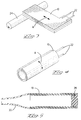
- a transducer according to the present invention is based on a piece of piezoelectric polymer film 10 which is metallised on either side with electrodes 12 and 14.
- the electrodes 12 and 14 have connector portions 12a and 14a brought out to one side of the transducer.
- the film 10 is laminated with an adhesive suitably in the form of a carrier tape 16 coated on each side with adhesive 18 and 20 as seen in Figure 2.
- contact pins 22 are fixed to the film/tape composite described above and the film/tape composite is then wrapped around a mandrel 24 in a scroll-like manner to form the transducer of the present invention.
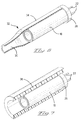
- the piezoelectric polymer film 10 is uniaxial film with the principal or machine axis aligned in the direction of the arrow A such that in the resulting transducer of Figure 4 the machine axis is circumferential.
- the transducer may be provided with a plug or base 26 which acts as an acoustic reflecting surface.
- the radiation (or reception) efficiency is enhanced by the plug or base 26, with a corresponding change occurring in the frequency response of the transducer, as with the end closed off, standing waves occur at a lower frequency than when the end is open.
- the transducer may optionally include a reducing nozzle 30 which further enhances radiation (or reception) efficiency by providing a reduction in diameter through which the acoustic waves are transmitted or received just in front of the transducer.
- Figure 6 illustrates the transducer of the present invention mounted as part of a cartridge 32 which includes the base 26 and the reducing nozzle 30, along with a cylindrical containment 34.
- Figure 7 shows the transducer of the present invention for use in propagating or detecting sound (acoustic waves) within a conduit 36.
- the conduit 36 for the acoustic signal is formed of a material which is electrically conductive or semi-conductive (such as carbon-loaded rubber) and thus may carry electrical signals unrelated to the acoustic signals being generated and detected by the transducer
- suitable piezoelectric polymer film material such as uniaxially-oriented PVDF (polyvinylidene fluoride) can withstand an applied electric field strength of around 30 volts per micrometer of thickness.
- the PVDF film has a thickness of 28 ⁇ m, hence the applied electrical drive signal should not exceed 840 volts.
- sound pressure levels in excess of 112dB may be detected after propagating a distance of one metre down a conduit 5mm in diameter.
- a similarly constructed transducer may show a sensitivity of -80dB (re 1 V/Pa).
- the foregoing example has the machine axis of the film circumferential.
- the machine axis could be slightly out of true circumferential alignment, provided the major directional component is circumferential, for example by winding the film in a shallow helix.
- a transducer according to the present invention has been found to operate successfully within certain ranges of frequency, particularly in the region of 2kHz to 25kHz when the transducer is tested in free space at close range. Since the attenuation of sound increases with frequency, the received signal after propagating some distance in air will show a corresponding reduction in signal content at high frequencies. For this reason, it is found preferable to operate such devices nearer the lower end of the range referred to above - i.e. in the region of 2kHz to 3kHz.
- the device thus allows transmission of acoustic waves through a duct or conduit, whereby a transducer according to the present invention could be disposed at each opposite ends of the duct or conduit with one being operated as a transmitter and the other as a receiver such that the signal could be passed therealong.
- a reflector could also be used at one end and electronics provided to switch one transducer between transmit and receive modes.
Landscapes
- Physics & Mathematics (AREA)
- Engineering & Computer Science (AREA)
- Acoustics & Sound (AREA)
- Signal Processing (AREA)
- Piezo-Electric Transducers For Audible Bands (AREA)
- Transducers For Ultrasonic Waves (AREA)
Applications Claiming Priority (2)
| Application Number | Priority Date | Filing Date | Title |
|---|---|---|---|
| GB9505003 | 1995-03-11 | ||
| GBGB9505003.5A GB9505003D0 (en) | 1995-03-11 | 1995-03-11 | "Acoustic transducer" |
Publications (1)
| Publication Number | Publication Date |
|---|---|
| EP0732864A2 true EP0732864A2 (de) | 1996-09-18 |
Family
ID=10771102
Family Applications (1)
| Application Number | Title | Priority Date | Filing Date |
|---|---|---|---|
| EP96103044A Withdrawn EP0732864A2 (de) | 1995-03-11 | 1996-02-29 | Akustischer Wandler |
Country Status (3)
| Country | Link |
|---|---|
| EP (1) | EP0732864A2 (de) |
| JP (1) | JP3930580B2 (de) |
| GB (1) | GB9505003D0 (de) |
Cited By (5)
| Publication number | Priority date | Publication date | Assignee | Title |
|---|---|---|---|---|
| US6441540B1 (en) * | 1999-11-05 | 2002-08-27 | Toray Techno Co., Ltd. | Cylindrical piezoelectric transducer and cylindrical piezoelectric vibrating element |
| EP1254585A4 (de) * | 1999-12-09 | 2008-10-29 | Sonionmicrotronic Nederland | Miniaturmikrofon |
| GB2579672A (en) * | 2018-12-12 | 2020-07-01 | Thales Holdings Uk Plc | A piezo-resistive hydrophone |
| CN111373768A (zh) * | 2017-11-21 | 2020-07-03 | 日东电工株式会社 | 用于形成压电扬声器的层叠体 |
| US12071761B2 (en) | 2017-11-21 | 2024-08-27 | Nitto Denko Corporation | Sound reducing system |
Families Citing this family (2)
| Publication number | Priority date | Publication date | Assignee | Title |
|---|---|---|---|---|
| JP5742944B2 (ja) * | 2011-08-24 | 2015-07-01 | 株式会社村田製作所 | アクチュエータ素子及び該アクチュエータ素子の製造方法 |
| US20200314555A1 (en) * | 2015-12-04 | 2020-10-01 | Harman Becker Automotive Systems Gmbh | Electro-active loudspeaker |
-
1995
- 1995-03-11 GB GBGB9505003.5A patent/GB9505003D0/en active Pending
-
1996
- 1996-02-29 EP EP96103044A patent/EP0732864A2/de not_active Withdrawn
- 1996-03-07 JP JP07957596A patent/JP3930580B2/ja not_active Expired - Fee Related
Cited By (8)
| Publication number | Priority date | Publication date | Assignee | Title |
|---|---|---|---|---|
| US6441540B1 (en) * | 1999-11-05 | 2002-08-27 | Toray Techno Co., Ltd. | Cylindrical piezoelectric transducer and cylindrical piezoelectric vibrating element |
| EP1254585A4 (de) * | 1999-12-09 | 2008-10-29 | Sonionmicrotronic Nederland | Miniaturmikrofon |
| CN111373768A (zh) * | 2017-11-21 | 2020-07-03 | 日东电工株式会社 | 用于形成压电扬声器的层叠体 |
| EP3716647A4 (de) * | 2017-11-21 | 2021-08-18 | Nitto Denko Corporation | Laminatkörper zur formung eines piezoelektrischen lautsprechers |
| US11252510B2 (en) | 2017-11-21 | 2022-02-15 | Nitto Denko Corporation | Piezoelectric speaker-forming laminate |
| US12071761B2 (en) | 2017-11-21 | 2024-08-27 | Nitto Denko Corporation | Sound reducing system |
| GB2579672A (en) * | 2018-12-12 | 2020-07-01 | Thales Holdings Uk Plc | A piezo-resistive hydrophone |
| GB2579672B (en) * | 2018-12-12 | 2021-01-06 | Thales Holdings Uk Plc | A piezo-resistive hydrophone |
Also Published As
| Publication number | Publication date |
|---|---|
| GB9505003D0 (en) | 1995-04-26 |
| JPH08265897A (ja) | 1996-10-11 |
| JP3930580B2 (ja) | 2007-06-13 |
Similar Documents
| Publication | Publication Date | Title |
|---|---|---|
| US5646470A (en) | Acoustic transducer | |
| CA1134939A (en) | Polymeric piezoelectric microprobe having a damper | |
| CN108989514A (zh) | 一种移动终端 | |
| CN110967050B (zh) | 适用于近距离探测的高频传感器 | |
| GB2029160A (en) | Electroacoustic vibration assemblies and transducers | |
| US5825902A (en) | Spherical piezoelectric speaker | |
| EP0732864A2 (de) | Akustischer Wandler | |
| EP0782370A3 (de) | Lautsprecher zur Abstrahlung von Schallwellen in alle Richtungen im Verhältnis zu einer Lautsprecherhalterungsfläche | |
| US5889873A (en) | Piezoelectric acoustic transducer | |
| GB1569352A (en) | Transducer assemblies and to methods for radiating and detecting energy | |
| JP2019535164A (ja) | ハイドロフォンとエネルギー変換方法及び複合ハイドロフォン | |
| US4796725A (en) | Electrostatic transducer | |
| US4737939A (en) | Composite transducer | |
| US20060078145A1 (en) | Narrow directional microphone | |
| JPH08265897A5 (de) | ||
| US5220538A (en) | Electro-acoustic transducer insulation structure | |
| CN211401235U (zh) | 适用于近距离探测的高频传感器 | |
| US5199004A (en) | Sealed acoustical element using conductive epoxy | |
| KR100405393B1 (ko) | 음향 트랜스듀서 | |
| WO2007024045A1 (en) | Contact structure of a film-type audio-speaker | |
| JP4515092B2 (ja) | 圧電フィルムで形成された円筒形超音波受信機及びトランシーバ | |
| CN103414987A (zh) | Pvdf/压电陶瓷收发换能器 | |
| US4924503A (en) | Electroacoustic transducer | |
| GB2141902A (en) | Composite transducer | |
| JPH0158920B2 (de) |
Legal Events
| Date | Code | Title | Description |
|---|---|---|---|
| PUAI | Public reference made under article 153(3) epc to a published international application that has entered the european phase |
Free format text: ORIGINAL CODE: 0009012 |
|
| AK | Designated contracting states |
Kind code of ref document: A2 Designated state(s): DE FR GB IT |
|
| STAA | Information on the status of an ep patent application or granted ep patent |
Free format text: STATUS: THE APPLICATION IS DEEMED TO BE WITHDRAWN |
|
| 18D | Application deemed to be withdrawn |
Effective date: 20030303 |