EP0732671A2 - Video decoder system - Google Patents
Video decoder system Download PDFInfo
- Publication number
- EP0732671A2 EP0732671A2 EP19960104130 EP96104130A EP0732671A2 EP 0732671 A2 EP0732671 A2 EP 0732671A2 EP 19960104130 EP19960104130 EP 19960104130 EP 96104130 A EP96104130 A EP 96104130A EP 0732671 A2 EP0732671 A2 EP 0732671A2
- Authority
- EP
- European Patent Office
- Prior art keywords
- picture
- data
- scan
- timing signal
- decoding
- Prior art date
- Legal status (The legal status is an assumption and is not a legal conclusion. Google has not performed a legal analysis and makes no representation as to the accuracy of the status listed.)
- Granted
Links
Images


Classifications
-
- H—ELECTRICITY
- H04—ELECTRIC COMMUNICATION TECHNIQUE
- H04N—PICTORIAL COMMUNICATION, e.g. TELEVISION
- H04N19/00—Methods or arrangements for coding, decoding, compressing or decompressing digital video signals
- H04N19/50—Methods or arrangements for coding, decoding, compressing or decompressing digital video signals using predictive coding
- H04N19/503—Methods or arrangements for coding, decoding, compressing or decompressing digital video signals using predictive coding involving temporal prediction
- H04N19/51—Motion estimation or motion compensation
- H04N19/577—Motion compensation with bidirectional frame interpolation, i.e. using B-pictures
-
- H—ELECTRICITY
- H04—ELECTRIC COMMUNICATION TECHNIQUE
- H04N—PICTORIAL COMMUNICATION, e.g. TELEVISION
- H04N19/00—Methods or arrangements for coding, decoding, compressing or decompressing digital video signals
- H04N19/42—Methods or arrangements for coding, decoding, compressing or decompressing digital video signals characterised by implementation details or hardware specially adapted for video compression or decompression, e.g. dedicated software implementation
- H04N19/423—Methods or arrangements for coding, decoding, compressing or decompressing digital video signals characterised by implementation details or hardware specially adapted for video compression or decompression, e.g. dedicated software implementation characterised by memory arrangements
- H04N19/426—Methods or arrangements for coding, decoding, compressing or decompressing digital video signals characterised by implementation details or hardware specially adapted for video compression or decompression, e.g. dedicated software implementation characterised by memory arrangements using memory downsizing methods
- H04N19/427—Display on the fly, e.g. simultaneous writing to and reading from decoding memory
-
- H—ELECTRICITY
- H04—ELECTRIC COMMUNICATION TECHNIQUE
- H04N—PICTORIAL COMMUNICATION, e.g. TELEVISION
- H04N19/00—Methods or arrangements for coding, decoding, compressing or decompressing digital video signals
- H04N19/60—Methods or arrangements for coding, decoding, compressing or decompressing digital video signals using transform coding
- H04N19/61—Methods or arrangements for coding, decoding, compressing or decompressing digital video signals using transform coding in combination with predictive coding
Definitions
- the present invention generally relates to a system for decoding an encoded video signal, and particularly, to a video decoder system for decoding a sequence of motion picture data, as it is encoded in accordance with an MPEG standard.
- MPEG1 MPEG1 standard
- Fig. 6 to 8 Fig. 6 to 8 and Tables 1 to 4.
- An MPEG video decoder system is adapted to decode a code sequnce comprising a sequence header (hereafter "SH") and a substantially independent group of pictures (hereafter "GOP”), as it is a sequence layer formatted to the MPEG by an MPEG video encoder system.
- SH sequence header
- GOP substantially independent group of pictures
- the MPEG provides for a GOP layer consisting of three types of pictures: an intra-frame coded picture (hereafter sometimes “I picture”) assuring an independency of the GOP, an inter-frame forward-directionally predictive picture (hereafter sometimes “P picture”) of which prediction needs a past I or P picture to be refererred to, and a bidirectionally predictive picture (hereafter sometimes "B picture”) of which a prediction needs a past I or P picture and a future P picture to be referred to.
- I picture intra-frame coded picture
- P picture inter-frame forward-directionally predictive picture
- B picture bidirectionally predictive picture
- the MPEG video decoder system is necessarily adapted to decode any and all of the three types of pictures.
- a typical conventional video decoder system for decoding a GOP i.e. an MPEG-formatted bitstream
- the system employs a pair of scan memories either for writing data therein and the other for reading data therefrom, in an alternating manner.
- N number of pictures in a GOP to be processed
- M period for an occurrence of I or P picture in the GOP
- Ii, Pi or Bi be an I, P or B picture located at an arbitrary i-th position in a sequence of reproduced pictures (hereafter sometimes "outputs" or ⁇ O ⁇ ), such that: "B0-B1-I2-B3-B4-P5-B6-B7-P8-B9-B10-P11-B12-B13-P14", the GOP has a picture sequence such that: "I2- B0-B1- P5 -B3-B4 -P8- B6-B7- P11- B9-B10 -P14 -B12-B13".
- Ij, Pj or Bj be an I, P or B picture at an arbitrary j-th order to occur as a picture in a picture sequence of a GOP such that: "I0-B1-B2-P3-B4-B5-P6-B7-B8-P9-B10-B11-P12-B13-B14", a reproduced picture sequence ⁇ O ⁇ has corresponding pictures rearranged such that: "B1-B2 -I0- B4-B5- P3 -B7-B8 -P6- B10-B11- P9 -B13-B14 -P12 ".
- Fig. 1 is a block diagram of a conventional video decoder system of such a type.
- the conventional system includes a demultiplexing decoder 1 for Huffman-decoding a sequence of input picture data DI, as they are MPEG-formatted, an inverse quantizer 2 for inverse-quantizing a set of Huffman-decoded data, and an inverse discrete cosine transform (hereafter "IDCT") section 3 for performing an IDCT of inverse-quantized data to provide a set of inverse-transformed data IT as ac-component data for P and B pictures or dc-component data for an I picture.
- IDCT inverse discrete cosine transform
- the conventional system further includes an adder 4 for adding the inverse-transformed data IT to a set of type-dependent prediction data DR as dc-component data for the P and B pictures or zero-value data for the I picture, to provide a set of reproduced pixel data PI and PP on the I and P pictures to be alternatively stored in a pair of frame memories 8 and 9, and a set of reproduced pixel data PB on the B picture to be alternatively stored in a pair of scan memories 10 and 11.
- an adder 4 for adding the inverse-transformed data IT to a set of type-dependent prediction data DR as dc-component data for the P and B pictures or zero-value data for the I picture, to provide a set of reproduced pixel data PI and PP on the I and P pictures to be alternatively stored in a pair of frame memories 8 and 9, and a set of reproduced pixel data PB on the B picture to be alternatively stored in a pair of scan memories 10 and 11.
- the data set DR should have a corresponding picture sequence to the data set IT, e.g. :
- the adder 4 is provided with a prediction signal select switch Sw1 responsive to a select signal MT supplied as a macroblock level picture-type identifier from the decoder 1, for a selection among an inter-framer forward MC (motion compensation) prediction signal M1 from an MD unit 6 of a half-pel (i.e. half pixel) accuracy, an inter-frame backward MC prediction signal M2 from another MC unit 7 of a half-pel accuracy, an inter-frame bidirectional MC prediction signal MPI as a mean value from an average calculator 5, and an intra-frame prediction signal.
- a prediction signal select switch Sw1 responsive to a select signal MT supplied as a macroblock level picture-type identifier from the decoder 1, for a selection among an inter-framer forward MC (motion compensation) prediction signal M1 from an MD unit 6 of a half-pel (i.e. half pixel) accuracy, an inter-frame backward MC prediction signal M2 from another MC unit 7 of a half-pel accuracy, an inter-frame bidirectional
- the MC units 6 and 7 are responsive to a decoded motion vector signal MV supplied from the decoder 1, for executing half-pel MC's of I and/or P pictures P(3k) and P(3k+3) in a previous frame, as they are read from the frame memories 8 and 9, respectively.
- the system of Fig. 1 further includes a picture select switch Sw2 responsive to a select signal PT supplied as a picture sequence identifier from the decoder 1, for a selection among I and/or P pictures F1/O and F2/O and a B picture OB in a current frame, as they are each scanned, single or double, to be read from a corresponding one of the frame and scan memories 8 to 10, to be output as ⁇ O ⁇ , and a timing generator 12 for generating a timing signal K for a decoding control.
- a select signal PT supplied as a picture sequence identifier from the decoder 1
- a select signal PT supplied as a picture sequence identifier from the decoder 1
- a select signal PT supplied as a picture sequence identifier from the decoder 1
- a select signal PT supplied as a picture sequence identifier from the decoder 1
- a select signal PT supplied as a picture sequence identifier from the decoder 1
- a select signal PT supplied
- Ip, Pq and Br be a p-th I picture, a q-th P picture and an r-th B picture in a GOP
- the input code sequence DI formatted to the MPEG has a picture sequence such that: "I1-P1-B1-B2-B3-P2- ⁇ ".
- I, P and B pictures i.e. PI, PP and PB
- the I and P pictures e.g. I1, P1, P2, ⁇
- block scan sequential line scan
- raster scan two-to-one line jump scan
- the B pictures are alternately written to the scan memories 10 and 11, wehrefrom they are alternately read as data OB (e.g. OB1, OB2 OB3) to be output.
- the MC-prediction decoding in MPEG (coding: 30 fields/s) is executed at a rate of one picture per frame. Therefore, as shown in Fig. 2, in application to an NTSC system (display: 60 fields/s), there occur ovalaps (eg. TL1, TL2) between neighboring periods (e.g. Tb1, Tb2, Tb3) for processing data of B pictures (e.g. B1, B2, B3) to be each written to a scan memories 10, 11 and raster-scanned to be twice read therefrom to output.
- ovalaps eg. TL1, TL2
- Tb1, Tb2, Tb3 neighboring periods
- B pictures e.g. B1, B2, B3
- an end portion (e.g. TL1) of a current write/read process overlaps a head portion (e.g. TL1) of a subsequent write/read process (e.g. Tb2), which means that, if a single scan memory is provided, either process (Tb1 or Tb2) has to be put in a waiting state, or alternately the subsequent process (Tb2) has to be delayed to eliminate an overlap, and a next one (Tb3) thereto as well.
- the conventional system employs the two scan memories 10 and 11 so that write/read operations can be made in an alternating manner, i.e. on one memory 10 for B1 picture, on the other memory 11 for B2 picture and on the memory 10 for B3 picture, outputting a picture sequence such that: "OI1-OI1-OB1-OB1-OB2-OB2-OB3-OB3-OP1-OP1-OP2- ⁇ ".
- the conventional system needing two scan memories for B pictures tends to have a relatively large storage capacity, resulting in an enlarged expensive system.
- a genus of the present invention provides a video decoder system comprising a decoder means for Huffman-decoding a set of Huffman-coded picture data, an inverse quantization means for inverse-quantizing the Huffman-decoded data, an inverse discrete cosine transformation means for inverse-discrete-cosine-transforming the inverse-quantized data to provide a set of first data, an adder means responsive to a first selection signal from the decoder means, for adding a selected one of prediction data sets to the set of first data to provide a corresponding one of first, second and third picture data sets representing pictures of first, second and third types, respectively, first and second frame memories accessible for alternatively writing therein data of the first and second picture data sets in frames by a predetermined block scan and reading therefrom the same in a predetermined raster scan order, a third frame memory accessible for writing therein data of the third picture data set in frames by the predetermined block scan and reading therefrom the same in the predetermined predetermined raster
- a video decoder system is permitted to have a single scan memory for effectively processing a third picture data set within a predetermined period of time, without a conventional need of delay.
- the predetermined block scan comprises a sequential line scan
- the predetermined raster scan comprises a two-to-one line jump scan
- the predetermined period comprises at least a half of a scan period of one of the frames minus a period for one line of the predetermined block scan.
- Fig. 3 is a block diagram of a video decoder system according to an embodiment of the invention.
- the video decoder system of Fig. 3 comprises a decoder 1, an inverse quantizer 2, an IDCT section 3, an adder 4, an average calculator 5, a pair of MC units 6 and 7, a pair of frame memories 8 and 9, a single scan memory 10, and a pair of select switches Sw1 and Sw2, like the system of Fig. 1.
- the system of Fig. 3 further comprises a timing signal generator 12A including a timing selector 121 which is responsive to a picture type signal PT supplied from the decoder 1, representing an I, P or B picture type, for selectively generating one of a timing signal K for decoding I and P pictures in a similar manner to the system of Fig. 1 and a timing signal KB for decoding B pictures at a higher speed than the signal K.
- a timing signal generator 12A including a timing selector 121 which is responsive to a picture type signal PT supplied from the decoder 1, representing an I, P or B picture type, for selectively generating one of a timing signal K for decoding I and P pictures in a similar manner to the system of Fig. 1 and a timing signal KB for decoding B pictures at a higher speed than the signal K.
- Ip, Pq and Br be a p-th I picture, a q-th P picture and an r-th B picture in a GOP
- an input code sequence DI formatted to the MPEG has a picture sequence such that: "I1-P1-B1-B2-B3-P2- ⁇ ".
- I, P and B pictures i.e. PI, PP and PB
- I and P pictures e.g. I1, P1, P2, ⁇
- the I and P pictures are written by a block scan at a rate of 30 fields (30 frames) per second, alternately into the frame memories 8 and 9, wherefrom they are read by a raster scan at a rate of 60 fields (30 frames) per second, alternately providing data F1, F2 corresponding to reference pictures for MC and data O (e.g. OI1), O (e.g. OP1) corresponding to reproduced pictures to be output.
- the B pictures (e.g. B1, B2, B3, ⁇ ) are each written to the scan memory 10, wehrefrom it is read as data OB (e.g. OB1, OB2, OB3) to be output.
- OB e.g. OB1, OB2, OB3
- the timing selector 121 responds thereto to generate the timing signal KB in place of the timing signal K, driving the system to execute a series of associated decoding steps of the B picture at a high speed, securing a necessary period (e.g. Tb1, Tb2, Tb3) for writing data of the B picture to the scan memory 10 and reading therefrom the same, to avoid an occurrence of an overlap time TL between neighboring periods (eg. Tb1-Tb2, Tb2-Tb3) for processing B pictures.
- a necessary period e.g. Tb1, Tb2, Tb3
- Such effects may be achieved via an unshown CPU responsible for the timing signal KB, or directly the signal KB that may act on each associated section or unit.
- a B1 picture is written to the scan memory 10 in a timing designated by the timing signal K difining a normal decoding perocess time TD1.
- a raster scan starts reading data OB1 of the written B1 picture, for the first time.
- the timing selector 121 of the timing signal generator 12A responding to the picture type signal PT, as it has been changed to be indicative of the B picture, switches the timing signal from K to KB, whereby a B2 picture is MC-prediction decoded at a high speed.
- a writing of the decoded B2 picture starts upon completion of a second reading of the data OB1, a writing of the decoded B2 picture starts.
- a writing of a B2 picture is required to start at least one BL before a first scan for reading data OB2 of the written B2 picture and end one BL before an end of the first reading of the B2 picture.
- a blanking period BT i.e. a data output interruption period between the second output of the data OB1 and the first output of the data OB2 is apparently longer than the one block line period BL, meeting a write start condition to the scan memory 10.
- a writing period TD2 of B2 picture as well as that TD3 of B3 picture may preferably be set to a half of one-frame period FT minus the one block line period BL, i.e. (1/2)FT - BL, whereto the timing signal KB is designed, permitting a high speed decoding process, so that the scan memory 10 mere one in number can serve for a complete write/read operation of B picture.
- a possible capacity reduction to a one-frame storage permits an effective reduction in a total memory capacity, resulting in a size-reduced inexpensive system.
- the MPEG is an internationally known standard. However, for a quick reference. Figs. 6 to 8 are appendixed hereto.
- Fig. 6 is an illustration of a layered structure of MPEG data, of which characteristics are listed in Tables 1 to 4 below.
- Fig. 7 is an illustration of a sequence of three types of pictures in a GOP of the MPEG data of Fig. 6.
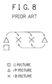
- Fig. 8 is a diagram describing directions of inter-frame MC predictions.
Abstract
Description
- The present invention generally relates to a system for decoding an encoded video signal, and particularly, to a video decoder system for decoding a sequence of motion picture data, as it is encoded in accordance with an MPEG standard.
- For a standardization of an inter-frame prediction coding of video signals such as for a TV, some drafts had been prepared by the Moving Picture Expert Group and examined by the ISO/IEC, JTC1/SC2/WG8.
- Among them, that one which provides for a decoder system has been provided for as an MPEG1 standard (hereafter simply "MPEG") in the Recommendation ISO/IEC-11172-2 (1993), see Fig. 6 to 8 and Tables 1 to 4.
- An MPEG video decoder system is adapted to decode a code sequnce comprising a sequence header (hereafter "SH") and a substantially independent group of pictures (hereafter "GOP"), as it is a sequence layer formatted to the MPEG by an MPEG video encoder system.
- Under the sequence layer, the MPEG provides for a GOP layer consisting of three types of pictures: an intra-frame coded picture (hereafter sometimes "I picture") assuring an independency of the GOP, an inter-frame forward-directionally predictive picture (hereafter sometimes "P picture") of which prediction needs a past I or P picture to be refererred to, and a bidirectionally predictive picture (hereafter sometimes "B picture") of which a prediction needs a past I or P picture and a future P picture to be referred to.
- In this respect, the MPEG video decoder system is necessarily adapted to decode any and all of the three types of pictures.
- A typical conventional video decoder system for decoding a GOP, i.e. an MPEG-formatted bitstream, has a decoding rate of one picture per one frame, whereas for the B picture to be scanned, the system employs a pair of scan memories either for writing data therein and the other for reading data therefrom, in an alternating manner.
- This is due to an inherent differece between an order of pictures to be processed and an order of reproduced pictures to be equivalent to that of original pictures.
- For example, letting N (number of pictures in a GOP to be processed) = 15, M (period for an occurrence of I or P picture in the GOP) = 3 and Ii, Pi or Bi be an I, P or B picture located at an arbitrary i-th position in a sequence of reproduced pictures (hereafter sometimes "outputs" or {O} ), such that:
"B0-B1-I2-B3-B4-P5-B6-B7-P8-B9-B10-P11-B12-B13-P14",
the GOP has a picture sequence such that:
"I2-B0-B1-P5-B3-B4-P8-B6-B7-P11-B9-B10-P14-B12-B13". - In other words, assuming Ij, Pj or Bj be an I, P or B picture at an arbitrary j-th order to occur as a picture in a picture sequence of a GOP such that:
"I0-B1-B2-P3-B4-B5-P6-B7-B8-P9-B10-B11-P12-B13-B14",
a reproduced picture sequence {O} has corresponding pictures rearranged such that:
"B1-B2-I0-B4-B5-P3-B7-B8-P6-B10-B11-P9-B13-B14-P12". - It will be seen that letting k = [j/3], where [x] means a largest integer not exceeding x, it so follows that:
GOP = {P(3k),B(3k+1),B(3k+2); k = 0 to 4 } and
{O} = {B(3k+1), B(3k+2), P(3k); k = 0 to 4 } ,
providing that P0 = I0. - Fig. 1 is a block diagram of a conventional video decoder system of such a type.
- The conventional system includes a demultiplexing decoder 1 for Huffman-decoding a sequence of input picture data DI, as they are MPEG-formatted, an
inverse quantizer 2 for inverse-quantizing a set of Huffman-decoded data, and an inverse discrete cosine transform (hereafter "IDCT")section 3 for performing an IDCT of inverse-quantized data to provide a set of inverse-transformed data IT as ac-component data for P and B pictures or dc-component data for an I picture. - Assuming a suffix "a" representing an ac-component (i. e. a pixel data difference between an original picture and a prediction picture) and a suffix "d" representing a dc-component (i.e. a pixel data of prediction picture), the data set IT has a picture sequence, e.g.:
IT = {Pa(3k),Ba(3k+1),Ba(3k+2); k = 0 to 4} ,
providing that Pa(3k) = Ia(3k) = Id for k = 0 and an ideal relationship between a coding and a decoding. - The conventional system further includes an
adder 4 for adding the inverse-transformed data IT to a set of type-dependent prediction data DR as dc-component data for the P and B pictures or zero-value data for the I picture, to provide a set of reproduced pixel data PI and PP on the I and P pictures to be alternatively stored in a pair offrame memories scan memories - The data set DR should have a corresponding picture sequence to the data set IT, e.g. :
- DR = {Pd(3k),Bd(3k+1),Bd(3k+2); k = 0 to 4} ,
providing that Pd(3k) = Id(3k) = 0 for k = 0. - Therefore, the
adder 4 is provided with a prediction signal select switch Sw1 responsive to a select signal MT supplied as a macroblock level picture-type identifier from the decoder 1, for a selection among an inter-framer forward MC (motion compensation) prediction signal M1 from anMD unit 6 of a half-pel (i.e. half pixel) accuracy, an inter-frame backward MC prediction signal M2 from anotherMC unit 7 of a half-pel accuracy, an inter-frame bidirectional MC prediction signal MPI as a mean value from anaverage calculator 5, and an intra-frame prediction signal. - The
MC units frame memories - The system of Fig. 1 further includes a picture select switch Sw2 responsive to a select signal PT supplied as a picture sequence identifier from the decoder 1, for a selection among I and/or P pictures F1/O and F2/O and a B picture OB in a current frame, as they are each scanned, single or double, to be read from a corresponding one of the frame and scan
memories 8 to 10, to be output as {O} , and atiming generator 12 for generating a timing signal K for a decoding control. - Fig. 2 shows a time chart of various signals in the system of Fig. 1, assuming that M = 4.
- Letting Ip, Pq and Br be a p-th I picture, a q-th P picture and an r-th B picture in a GOP, it is now assumed that the input code sequence DI formatted to the MPEG has a picture sequence such that:
"I1-P1-B1-B2-B3-P2-···". - In accordance with the control by the timing signal K, there are MC-prediction decoded I, P and B pictures (i.e. PI, PP and PB), of which the I and P pictures (e.g. I1, P1, P2, ···) are written by a sequential line scan (hereafter "block scan") at a rate of 30 fields (30 frames) per second, alternately into the
frame memories scan memories - The MC-prediction decoding in MPEG (coding: 30 fields/s) is executed at a rate of one picture per frame. Therefore, as shown in Fig. 2, in application to an NTSC system (display: 60 fields/s), there occur ovalaps (eg. TL1, TL2) between neighboring periods (e.g. Tb1, Tb2, Tb3) for processing data of B pictures (e.g. B1, B2, B3) to be each written to a
scan memories - Namely, an end portion (e.g. TL1) of a current write/read process (e.g. Tb1) overlaps a head portion (e.g. TL1) of a subsequent write/read process (e.g. Tb2), which means that, if a single scan memory is provided, either process (Tb1 or Tb2) has to be put in a waiting state, or alternately the subsequent process (Tb2) has to be delayed to eliminate an overlap, and a next one (Tb3) thereto as well.
- To avoid such an undesirable delay accumulation, the conventional system employs the two
scan memories memory 10 for B1 picture, on theother memory 11 for B2 picture and on thememory 10 for B3 picture, outputting a picture sequence such that:
"OI1-OI1-OB1-OB1-OB2-OB2-OB3-OB3-OP1-OP1-OP2-···". - Necessary storage capacity for frame and scan memories (= 4 frames) is calculatable such that:
352 (dots) × 288 (lines) × 8 (bits) × 1.5 (Y+Cb+Cr) × 4 (frames) = 4,866,048 (bits). - Like this, the conventional system needing two scan memories for B pictures tends to have a relatively large storage capacity, resulting in an enlarged expensive system.
- The present invention has been achieved with such points in mind.
- It therefore is an object of the present invention to provide a video decoder system having a reduced storage capacity.
- To achieve the object, a genus of the present invention provides a video decoder system comprising a decoder means for Huffman-decoding a set of Huffman-coded picture data, an inverse quantization means for inverse-quantizing the Huffman-decoded data, an inverse discrete cosine transformation means for inverse-discrete-cosine-transforming the inverse-quantized data to provide a set of first data, an adder means responsive to a first selection signal from the decoder means, for adding a selected one of prediction data sets to the set of first data to provide a corresponding one of first, second and third picture data sets representing pictures of first, second and third types, respectively, first and second frame memories accessible for alternatively writing therein data of the first and second picture data sets in frames by a predetermined block scan and reading therefrom the same in a predetermined raster scan order, a third frame memory accessible for writing therein data of the third picture data set in frames by the predetermined block scan and reading therefrom the same in the predetermined raster scan order, and a timing signal generation means for generating a timing signal for a timing control of the video decoder system, wherein the timing signal generation means includes a timing signal select means responsive to a picture type signal indicating an arbitrary one of the first, second and third types for selectively generating one of a first said timing signal for decoding the first and second picture data sets and a second said timing signal for decoding the third picture data set within a predetermined period of time.
- Therefore, according to the genus of the invention, a video decoder system is permitted to have a single scan memory for effectively processing a third picture data set within a predetermined period of time, without a conventional need of delay.
- According to a species of the genus of the invention, the predetermined block scan comprises a sequential line scan, the predetermined raster scan comprises a two-to-one line jump scan, and the predetermined period comprises at least a half of a scan period of one of the frames minus a period for one line of the predetermined block scan.
- The objects, features and advantages of the present invention will become more apparent from consideration of the following detailed description, in conjunction with the accompanying drawings, in which:
- Fig. 1 is a block diagram of a conventional video decoder system;
- Fig. 2 is a time chart of various signals in the system of Fig. 1;
- Fig. 3 is a block diagram of a video decoder system according to an embodiment of the invention;
- Figs. 4 and 5 are time charts of various signals in the system of Fig. 3, respectively;
- Fig. 6 is an illustration of a layered structure of MPEG data;
- Fig. 7 is an illustration of a sequence of three types of pictures in a GOP of the MPEG data of Fig. 6; and
- Fig. 8 is a diagram describing directions of inter-frame MC predictions.
- There will be detailed below preferred embodiments of the present invention, with reference to the accompanying drawings. Like members are designated by like reference characters.
- Fig. 3 is a block diagram of a video decoder system according to an embodiment of the invention.
- The video decoder system of Fig. 3 comprises a decoder 1, an
inverse quantizer 2, anIDCT section 3, anadder 4, anaverage calculator 5, a pair ofMC units frame memories single scan memory 10, and a pair of select switches Sw1 and Sw2, like the system of Fig. 1. - The system of Fig. 3 further comprises a
timing signal generator 12A including atiming selector 121 which is responsive to a picture type signal PT supplied from the decoder 1, representing an I, P or B picture type, for selectively generating one of a timing signal K for decoding I and P pictures in a similar manner to the system of Fig. 1 and a timing signal KB for decoding B pictures at a higher speed than the signal K. - Fig. 4 and 5 show time charts of various signals in the system of Fig. 3, assuming that M = 4.
- Again letting Ip, Pq and Br be a p-th I picture, a q-th P picture and an r-th B picture in a GOP, it is assumed that an input code sequence DI formatted to the MPEG has a picture sequence such that:
"I1-P1-B1-B2-B3-P2-···". - Like the system of Fig. 1, in accordance with the control by the timing signal K, there are MC-prediction decoded I, P and B pictures (i.e. PI, PP and PB), of which the I and P pictures (e.g. I1, P1, P2,···) are written by a block scan at a rate of 30 fields (30 frames) per second, alternately into the
frame memories - The B pictures (e.g. B1, B2, B3, ···) are each written to the
scan memory 10, wehrefrom it is read as data OB (e.g. OB1, OB2, OB3) to be output. - When the picture type signal PT supplied from the decoder 1 is changed, indicating a B picture, the
timing selector 121 responds thereto to generate the timing signal KB in place of the timing signal K, driving the system to execute a series of associated decoding steps of the B picture at a high speed, securing a necessary period (e.g. Tb1, Tb2, Tb3) for writing data of the B picture to thescan memory 10 and reading therefrom the same, to avoid an occurrence of an overlap time TL between neighboring periods (eg. Tb1-Tb2, Tb2-Tb3) for processing B pictures. Such effects may be achieved via an unshown CPU responsible for the timing signal KB, or directly the signal KB that may act on each associated section or unit. - More specifically, as shown in Fig. 5, a B1 picture is written to the
scan memory 10 in a timing designated by the timing signal K difining a normal decoding perocess time TD1. In a rear half of the writing time TD1, a raster scan starts reading data OB1 of the written B1 picture, for the first time. In concurrence therewith, thetiming selector 121 of thetiming signal generator 12A responding to the picture type signal PT, as it has been changed to be indicative of the B picture, switches the timing signal from K to KB, whereby a B2 picture is MC-prediction decoded at a high speed. As a result, upon completion of a second reading of the data OB1, a writing of the decoded B2 picture starts. - To effectively avoid an overlap between neighboring B picture write/read process periods Tb1 and Tb2, letting BL be a fraction of a block scan that corresponds to one block line (i.e. one block line period), a writing of a B2 picture is required to start at least one BL before a first scan for reading data OB2 of the written B2 picture and end one BL before an end of the first reading of the B2 picture.
- In this respect, a blanking period BT, i.e. a data output interruption period between the second output of the data OB1 and the first output of the data OB2, is apparently longer than the one block line period BL, meeting a write start condition to the
scan memory 10. - Therefore, to avoid an overlap between neighboring B picture write/read process periods, a writing period TD2 of B2 picture as well as that TD3 of B3 picture may preferably be set to a half of one-frame period FT minus the one block line period BL, i.e. (1/2)FT - BL, whereto the timing signal KB is designed, permitting a high speed decoding process, so that the
scan memory 10 mere one in number can serve for a complete write/read operation of B picture. - Necessary storage capacity for frame and scan memories (= 3 frames) is calculatable such that:
352 (dots) × 288 (lines) × 8 (bits) × 1.5 (Y+Cb+Cr) × 3 (frames) = 3,649,536 (bits),
so that a single 4M RAM affords a competent use. - According to the embodiment of Fig. 3, therefore, a possible capacity reduction to a one-frame storage permits an effective reduction in a total memory capacity, resulting in a size-reduced inexpensive system.
- Incidentally, the MPEG is an internationally known standard. However, for a quick reference. Figs. 6 to 8 are appendixed hereto.
- Fig. 6 is an illustration of a layered structure of MPEG data, of which characteristics are listed in Tables 1 to 4 below.


- Fig. 7 is an illustration of a sequence of three types of pictures in a GOP of the MPEG data of Fig. 6.
- Fig. 8 is a diagram describing directions of inter-frame MC predictions.
- While the present invention has been described with reference to the particular illustrative embodiments, it is not to be restricted by those embodiments but only by the appended claims. It is to be appreciated that those skilled in the art can change or modify the embodiments without departing from the scope and spirit of the present invention.
Claims (2)
- A video decoder system comprising:a decoder means (1) for Huffman-decoding a set of Huffman-coded picture data;an inverse quantization means (2) for inverse-quantizing the Huffman-decoded data;an inverse discrete cosine transformation means (3) for inverse―discrete-cosine-transforming the inverse-quantized data to provide a set of first data;an adder means (4) responsive to a first selection signal from the decoder means, for adding a selected one of prediction data sets to the set of first data to provide a corresponding one of first, second and third picture data sets representing pictures of first, second and third types, respectively;first and second frame memories (8, 9) accessible for alternatively writing therein data of the first and second picture data sets in frames by a predetermined block scan and reading therefrom the same in a predetermined raster scan order;a third frame memory (10) accessible for writing therein data of the third picture data set in frames by the predetermined block scan and reading therefrom the same in the predetermined raster scan order; anda timing signal generation means (12A) for generating a timing signal for a timing control of the video decoder system, wherein:the timing signal generation means (12A) includes a timing signal select means (121) responsive to a picture type signal (PT) indicating an arbitrary one of the first, second and third types for selectively generating one of a first said timing signal (K) for decoding the first and second picture data sets and a second said timing signal (KB) for decoding the third picture data set within a predetermined period (TD2) of time.
- A video decoder system according to claim 1, wherein:the predetermined block scan comprises a sequential line scan;the predetermined raster scan comprises a two-to-one line jump scan; andthe predetermined period (TD2) comprises at least a half of a scan period of one of the frames minus a period for one line of the predetermined block scan.
Applications Claiming Priority (3)
| Application Number | Priority Date | Filing Date | Title |
|---|---|---|---|
| JP5784495A JP2935340B2 (en) | 1995-03-17 | 1995-03-17 | Video decoding device |
| JP57844/95 | 1995-03-17 | ||
| JP5784495 | 1995-03-17 |
Publications (3)
| Publication Number | Publication Date |
|---|---|
| EP0732671A2 true EP0732671A2 (en) | 1996-09-18 |
| EP0732671A3 EP0732671A3 (en) | 1997-04-09 |
| EP0732671B1 EP0732671B1 (en) | 2001-11-14 |
Family
ID=13067293
Family Applications (1)
| Application Number | Title | Priority Date | Filing Date |
|---|---|---|---|
| EP19960104130 Expired - Lifetime EP0732671B1 (en) | 1995-03-17 | 1996-03-15 | Video decoder system |
Country Status (4)
| Country | Link |
|---|---|
| US (1) | US5727091A (en) |
| EP (1) | EP0732671B1 (en) |
| JP (1) | JP2935340B2 (en) |
| DE (1) | DE69616850T2 (en) |
Cited By (1)
| Publication number | Priority date | Publication date | Assignee | Title |
|---|---|---|---|---|
| US5727091A (en) * | 1995-03-17 | 1998-03-10 | Nec Corporation | Video decoder system |
Families Citing this family (8)
| Publication number | Priority date | Publication date | Assignee | Title |
|---|---|---|---|---|
| US7075991B1 (en) | 1993-01-18 | 2006-07-11 | Sony Corporation | Apparatus for encoding and decoding header data in picture signal transmission |
| EP0825781B1 (en) | 1996-08-22 | 2004-10-27 | Matsushita Electric Industrial Co., Ltd. | Image processor |
| WO2000019376A1 (en) * | 1998-09-29 | 2000-04-06 | Koninklijke Philips Electronics N.V. | Partition decoding method and device |
| US6999511B1 (en) * | 1999-02-23 | 2006-02-14 | International Business Machines Corporation | Dynamically switching quant matrix tables within an MPEG-2 encoder |
| AU3397700A (en) | 1999-03-12 | 2000-09-28 | Fortel Dtv, Inc. | Digital comb filter |
| US7046299B1 (en) | 2000-09-29 | 2006-05-16 | Fortel, Dtv | Digital video synchronizer with both decoded digital and undecoded analog outputs |
| US7327405B1 (en) | 2003-04-04 | 2008-02-05 | Qustream Corporation | Systems and methods for improved video comb filtering with dynamic chroma bandwidth control |
| US8204104B2 (en) * | 2006-03-09 | 2012-06-19 | Sony Corporation | Frame rate conversion system, method of converting frame rate, transmitter, and receiver |
Citations (3)
| Publication number | Priority date | Publication date | Assignee | Title |
|---|---|---|---|---|
| US5293229A (en) * | 1992-03-27 | 1994-03-08 | Matsushita Electric Corporation Of America | Apparatus and method for processing groups of fields in a video data compression system |
| US5329365A (en) * | 1993-07-07 | 1994-07-12 | Rca Thomson Licensing Corporation | Method and apparatus for providing compressed non-interlaced scanned video signal |
| EP0675656A2 (en) * | 1994-03-31 | 1995-10-04 | Victor Company Of Japan, Ltd. | Moving image coding device |
Family Cites Families (7)
| Publication number | Priority date | Publication date | Assignee | Title |
|---|---|---|---|---|
| JP3184011B2 (en) * | 1992-07-20 | 2001-07-09 | 株式会社東芝 | Band compression signal processor |
| EP0585051B1 (en) * | 1992-08-21 | 2001-03-07 | Canon Kabushiki Kaisha | Image processing method and apparatus |
| JPH06178274A (en) * | 1992-11-30 | 1994-06-24 | Sony Corp | Motion picture decoding device |
| EP0627855B1 (en) * | 1993-05-31 | 2001-11-07 | Sony Corporation | Digital video signal recording |
| US5398072A (en) * | 1993-10-25 | 1995-03-14 | Lsi Logic Corporation | Management of channel buffer in video decoders |
| US5592226A (en) * | 1994-01-26 | 1997-01-07 | Btg Usa Inc. | Method and apparatus for video data compression using temporally adaptive motion interpolation |
| JP2935340B2 (en) * | 1995-03-17 | 1999-08-16 | 日本電気株式会社 | Video decoding device |
-
1995
- 1995-03-17 JP JP5784495A patent/JP2935340B2/en not_active Expired - Fee Related
-
1996
- 1996-03-13 US US08/614,474 patent/US5727091A/en not_active Expired - Lifetime
- 1996-03-15 EP EP19960104130 patent/EP0732671B1/en not_active Expired - Lifetime
- 1996-03-15 DE DE1996616850 patent/DE69616850T2/en not_active Expired - Lifetime
Patent Citations (3)
| Publication number | Priority date | Publication date | Assignee | Title |
|---|---|---|---|---|
| US5293229A (en) * | 1992-03-27 | 1994-03-08 | Matsushita Electric Corporation Of America | Apparatus and method for processing groups of fields in a video data compression system |
| US5329365A (en) * | 1993-07-07 | 1994-07-12 | Rca Thomson Licensing Corporation | Method and apparatus for providing compressed non-interlaced scanned video signal |
| EP0675656A2 (en) * | 1994-03-31 | 1995-10-04 | Victor Company Of Japan, Ltd. | Moving image coding device |
Non-Patent Citations (1)
| Title |
|---|
| 1993 IEEE INTERNATIONAL SOLID-STATE CIRCUITS CONFERENCE. DIGEST OF TECHNICAL PAPERS. ISSCC. FIRST EDITION (CAT. NO.93CH3272-2), PROCEEDINGS OF IEEE INTERNATIONAL SOLID-STATE CIRCUITS CONFERENCE - ISSCC '93, SAN FRANCISCO, CA, USA, 24-26 FEB. 1993, ISBN 0-7803-0987-1, 1993, NEW YORK, NY, USA, IEEE, USA, pages 34-35, XP000609672 BRINTHAUPT D ET AL: "A video decoder for H.261 video teleconferencing and MPEG stored interactive video applications" * |
Cited By (1)
| Publication number | Priority date | Publication date | Assignee | Title |
|---|---|---|---|---|
| US5727091A (en) * | 1995-03-17 | 1998-03-10 | Nec Corporation | Video decoder system |
Also Published As
| Publication number | Publication date |
|---|---|
| DE69616850D1 (en) | 2001-12-20 |
| US5727091A (en) | 1998-03-10 |
| JP2935340B2 (en) | 1999-08-16 |
| DE69616850T2 (en) | 2002-06-06 |
| EP0732671B1 (en) | 2001-11-14 |
| JPH08256331A (en) | 1996-10-01 |
| EP0732671A3 (en) | 1997-04-09 |
Similar Documents
| Publication | Publication Date | Title |
|---|---|---|
| EP0542195B1 (en) | Interframe predicting method and picture signal coding/decoding apparatus | |
| EP0431319B1 (en) | Video signal coding apparatus, coding method and video signal coding transmission system | |
| US5991443A (en) | Graphics image manipulation | |
| KR100253931B1 (en) | Approximate mpeg decoder with compressed reference frames | |
| JP3268306B2 (en) | Image coding method | |
| US4933763A (en) | Method of and arrangement for coding digital video signals and corresponding decoding arrangement | |
| US5841475A (en) | Image decoding with dedicated bidirectional picture storage and reduced memory requirements | |
| US6415055B1 (en) | Moving image encoding method and apparatus, and moving image decoding method and apparatus | |
| JP2001211455A (en) | Image coding method and image coder | |
| US5751888A (en) | Moving picture signal decoder | |
| US5936670A (en) | Method and device for decoding coded digital video signals | |
| US5757967A (en) | Digital video decoder and deinterlacer, format/frame rate converter with common memory | |
| US5991445A (en) | Image processing apparatus | |
| EP0732671B1 (en) | Video decoder system | |
| KR100267125B1 (en) | Decoding and displaying method of compressing digital video sequence and decoding device of compressing digital video information | |
| EP0658053B1 (en) | Apparatus for decoding time-varying image | |
| US5343256A (en) | Image coding apparatus | |
| JPH10271516A (en) | Compression coder, coding method, decoder and decoding method | |
| KR100472564B1 (en) | Image processor | |
| JPH06225279A (en) | Coding/decoding methods and coding/decoding devices | |
| US6097843A (en) | Compression encoding apparatus, encoding method, decoding apparatus, and decoding method | |
| JP2898413B2 (en) | Method for decoding and encoding compressed video data streams with reduced memory requirements | |
| US6128340A (en) | Decoder system with 2.53 frame display buffer | |
| JPH10145237A (en) | Compressed data decoding device | |
| JP3308129B2 (en) | Image signal decoding method and image signal decoding device |
Legal Events
| Date | Code | Title | Description |
|---|---|---|---|
| PUAI | Public reference made under article 153(3) epc to a published international application that has entered the european phase |
Free format text: ORIGINAL CODE: 0009012 |
|
| AK | Designated contracting states |
Kind code of ref document: A2 Designated state(s): DE FR GB |
|
| PUAL | Search report despatched |
Free format text: ORIGINAL CODE: 0009013 |
|
| AK | Designated contracting states |
Kind code of ref document: A3 Designated state(s): DE FR GB |
|
| 17P | Request for examination filed |
Effective date: 19970707 |
|
| 17Q | First examination report despatched |
Effective date: 20000309 |
|
| GRAG | Despatch of communication of intention to grant |
Free format text: ORIGINAL CODE: EPIDOS AGRA |
|
| GRAG | Despatch of communication of intention to grant |
Free format text: ORIGINAL CODE: EPIDOS AGRA |
|
| GRAH | Despatch of communication of intention to grant a patent |
Free format text: ORIGINAL CODE: EPIDOS IGRA |
|
| GRAH | Despatch of communication of intention to grant a patent |
Free format text: ORIGINAL CODE: EPIDOS IGRA |
|
| GRAA | (expected) grant |
Free format text: ORIGINAL CODE: 0009210 |
|
| AK | Designated contracting states |
Kind code of ref document: B1 Designated state(s): DE FR GB |
|
| REF | Corresponds to: |
Ref document number: 69616850 Country of ref document: DE Date of ref document: 20011220 |
|
| REG | Reference to a national code |
Ref country code: GB Ref legal event code: IF02 |
|
| ET | Fr: translation filed | ||
| PLBE | No opposition filed within time limit |
Free format text: ORIGINAL CODE: 0009261 |
|
| STAA | Information on the status of an ep patent application or granted ep patent |
Free format text: STATUS: NO OPPOSITION FILED WITHIN TIME LIMIT |
|
| 26N | No opposition filed | ||
| REG | Reference to a national code |
Ref country code: GB Ref legal event code: 732E |
|
| REG | Reference to a national code |
Ref country code: FR Ref legal event code: TP |
|
| REG | Reference to a national code |
Ref country code: FR Ref legal event code: CD |
|
| REG | Reference to a national code |
Ref country code: DE Ref legal event code: R082 Ref document number: 69616850 Country of ref document: DE Representative=s name: BETTEN & RESCH, DE |
|
| REG | Reference to a national code |
Ref country code: DE Ref legal event code: R082 Ref document number: 69616850 Country of ref document: DE Representative=s name: BETTEN & RESCH PATENT- UND RECHTSANWAELTE PART, DE Effective date: 20120828 Ref country code: DE Ref legal event code: R082 Ref document number: 69616850 Country of ref document: DE Representative=s name: PATENTANWAELTE BETTEN & RESCH, DE Effective date: 20120828 Ref country code: DE Ref legal event code: R081 Ref document number: 69616850 Country of ref document: DE Owner name: RENESAS ELECTRONICS CORPORATION, KAWASAKI-SHI, JP Free format text: FORMER OWNER: NEC ELECTRONICS CORP., KAWASAKI, KANAGAWA, JP Effective date: 20120828 Ref country code: DE Ref legal event code: R081 Ref document number: 69616850 Country of ref document: DE Owner name: RENESAS ELECTRONICS CORPORATION, JP Free format text: FORMER OWNER: NEC ELECTRONICS CORP., KAWASAKI, JP Effective date: 20120828 |
|
| PGFP | Annual fee paid to national office [announced via postgrant information from national office to epo] |
Ref country code: GB Payment date: 20130313 Year of fee payment: 18 Ref country code: FR Payment date: 20130325 Year of fee payment: 18 Ref country code: DE Payment date: 20130314 Year of fee payment: 18 |
|
| REG | Reference to a national code |
Ref country code: DE Ref legal event code: R119 Ref document number: 69616850 Country of ref document: DE |
|
| GBPC | Gb: european patent ceased through non-payment of renewal fee |
Effective date: 20140315 |
|
| REG | Reference to a national code |
Ref country code: FR Ref legal event code: ST Effective date: 20141128 |
|
| REG | Reference to a national code |
Ref country code: DE Ref legal event code: R119 Ref document number: 69616850 Country of ref document: DE Effective date: 20141001 |
|
| PG25 | Lapsed in a contracting state [announced via postgrant information from national office to epo] |
Ref country code: DE Free format text: LAPSE BECAUSE OF NON-PAYMENT OF DUE FEES Effective date: 20141001 Ref country code: FR Free format text: LAPSE BECAUSE OF NON-PAYMENT OF DUE FEES Effective date: 20140331 Ref country code: GB Free format text: LAPSE BECAUSE OF NON-PAYMENT OF DUE FEES Effective date: 20140315 |