EP0732486B1 - Stamp formed muffler with nested chambers - Google Patents
Stamp formed muffler with nested chambers Download PDFInfo
- Publication number
- EP0732486B1 EP0732486B1 EP95112466A EP95112466A EP0732486B1 EP 0732486 B1 EP0732486 B1 EP 0732486B1 EP 95112466 A EP95112466 A EP 95112466A EP 95112466 A EP95112466 A EP 95112466A EP 0732486 B1 EP0732486 B1 EP 0732486B1
- Authority
- EP
- European Patent Office
- Prior art keywords
- muffler
- downstream
- chamber
- tubes
- plate
- Prior art date
- Legal status (The legal status is an assumption and is not a legal conclusion. Google has not performed a legal analysis and makes no representation as to the accuracy of the status listed.)
- Expired - Lifetime
Links
Images


Classifications
-
- F—MECHANICAL ENGINEERING; LIGHTING; HEATING; WEAPONS; BLASTING
- F01—MACHINES OR ENGINES IN GENERAL; ENGINE PLANTS IN GENERAL; STEAM ENGINES
- F01N—GAS-FLOW SILENCERS OR EXHAUST APPARATUS FOR MACHINES OR ENGINES IN GENERAL; GAS-FLOW SILENCERS OR EXHAUST APPARATUS FOR INTERNAL COMBUSTION ENGINES
- F01N13/00—Exhaust or silencing apparatus characterised by constructional features ; Exhaust or silencing apparatus, or parts thereof, having pertinent characteristics not provided for in, or of interest apart from, groups F01N1/00 - F01N5/00, F01N9/00, F01N11/00
- F01N13/18—Construction facilitating manufacture, assembly, or disassembly
- F01N13/1872—Construction facilitating manufacture, assembly, or disassembly the assembly using stamp-formed parts or otherwise deformed sheet-metal
- F01N13/1877—Construction facilitating manufacture, assembly, or disassembly the assembly using stamp-formed parts or otherwise deformed sheet-metal the channels or tubes thereof being made integrally with the housing
-
- F—MECHANICAL ENGINEERING; LIGHTING; HEATING; WEAPONS; BLASTING
- F01—MACHINES OR ENGINES IN GENERAL; ENGINE PLANTS IN GENERAL; STEAM ENGINES
- F01N—GAS-FLOW SILENCERS OR EXHAUST APPARATUS FOR MACHINES OR ENGINES IN GENERAL; GAS-FLOW SILENCERS OR EXHAUST APPARATUS FOR INTERNAL COMBUSTION ENGINES
- F01N1/00—Silencing apparatus characterised by method of silencing
- F01N1/02—Silencing apparatus characterised by method of silencing by using resonance
-
- F—MECHANICAL ENGINEERING; LIGHTING; HEATING; WEAPONS; BLASTING
- F01—MACHINES OR ENGINES IN GENERAL; ENGINE PLANTS IN GENERAL; STEAM ENGINES
- F01N—GAS-FLOW SILENCERS OR EXHAUST APPARATUS FOR MACHINES OR ENGINES IN GENERAL; GAS-FLOW SILENCERS OR EXHAUST APPARATUS FOR INTERNAL COMBUSTION ENGINES
- F01N1/00—Silencing apparatus characterised by method of silencing
- F01N1/08—Silencing apparatus characterised by method of silencing by reducing exhaust energy by throttling or whirling
- F01N1/084—Silencing apparatus characterised by method of silencing by reducing exhaust energy by throttling or whirling the gases flowing through the silencer two or more times longitudinally in opposite directions, e.g. using parallel or concentric tubes
-
- F—MECHANICAL ENGINEERING; LIGHTING; HEATING; WEAPONS; BLASTING
- F01—MACHINES OR ENGINES IN GENERAL; ENGINE PLANTS IN GENERAL; STEAM ENGINES
- F01N—GAS-FLOW SILENCERS OR EXHAUST APPARATUS FOR MACHINES OR ENGINES IN GENERAL; GAS-FLOW SILENCERS OR EXHAUST APPARATUS FOR INTERNAL COMBUSTION ENGINES
- F01N13/00—Exhaust or silencing apparatus characterised by constructional features ; Exhaust or silencing apparatus, or parts thereof, having pertinent characteristics not provided for in, or of interest apart from, groups F01N1/00 - F01N5/00, F01N9/00, F01N11/00
- F01N13/18—Construction facilitating manufacture, assembly, or disassembly
- F01N13/1872—Construction facilitating manufacture, assembly, or disassembly the assembly using stamp-formed parts or otherwise deformed sheet-metal
-
- F—MECHANICAL ENGINEERING; LIGHTING; HEATING; WEAPONS; BLASTING
- F01—MACHINES OR ENGINES IN GENERAL; ENGINE PLANTS IN GENERAL; STEAM ENGINES
- F01N—GAS-FLOW SILENCERS OR EXHAUST APPARATUS FOR MACHINES OR ENGINES IN GENERAL; GAS-FLOW SILENCERS OR EXHAUST APPARATUS FOR INTERNAL COMBUSTION ENGINES
- F01N2470/00—Structure or shape of gas passages, pipes or tubes
- F01N2470/06—Tubes being formed by assembly of stamped or otherwise deformed sheet-metal
-
- F—MECHANICAL ENGINEERING; LIGHTING; HEATING; WEAPONS; BLASTING
- F01—MACHINES OR ENGINES IN GENERAL; ENGINE PLANTS IN GENERAL; STEAM ENGINES
- F01N—GAS-FLOW SILENCERS OR EXHAUST APPARATUS FOR MACHINES OR ENGINES IN GENERAL; GAS-FLOW SILENCERS OR EXHAUST APPARATUS FOR INTERNAL COMBUSTION ENGINES
- F01N2470/00—Structure or shape of gas passages, pipes or tubes
- F01N2470/08—Gas passages being formed between the walls of an outer shell and an inner chamber
-
- F—MECHANICAL ENGINEERING; LIGHTING; HEATING; WEAPONS; BLASTING
- F01—MACHINES OR ENGINES IN GENERAL; ENGINE PLANTS IN GENERAL; STEAM ENGINES
- F01N—GAS-FLOW SILENCERS OR EXHAUST APPARATUS FOR MACHINES OR ENGINES IN GENERAL; GAS-FLOW SILENCERS OR EXHAUST APPARATUS FOR INTERNAL COMBUSTION ENGINES
- F01N2490/00—Structure, disposition or shape of gas-chambers
- F01N2490/15—Plurality of resonance or dead chambers
- F01N2490/155—Plurality of resonance or dead chambers being disposed one after the other in flow direction
Definitions
- the subject invention relates to an exhaust muffler manufactured from formed components.
- the muffler provides several acoustical tuning options for efficiently attenuating the noise associated with the flow of exhaust gas.
- the most commonly used prior art exhaust muffler includes a plurality of separate parallel tubes that are supported by transversely extending planar baffles of oval or circular shape.
- the assembly of tubes and baffles is slid into a tubular shell that has a cross-sectional configuration conforming to the shape of the baffles.
- An outer wrapper may be wrapped around the shell for additional strength and noise insulation.
- Opposed end caps or headers are then mechanically connected to the opposed ends of the shell and wrapper to enclose the muffler.
- Each end cap includes an aperture to define an inlet to or outlet from the muffler.
- Each chamber is enclosed by the tubular outer shell.
- Some of the tubes in the prior art muffler may terminate in a chamber. Others will pass entirely through a chamber. Portions of tubes in certain chambers will have louvers or perforations to permit gas communication between the tube and the surrounding chamber.
- Exhaust gas in the above described prior art muffler flows from tubes into the surrounding chambers and from the chambers into other tubes.
- the particular pattern of exhaust gas flow will vary from one muffler design to another.
- many prior art mufflers utilize a tri-flow pattern.
- Exhaust gas enters the upstream end of a tri-flow muffler and flows to a reversing chamber near the opposed downstream end.
- the exhaust gas then undergoes a substantially 180° change in direction and flows back toward the upstream end of the muffler to a second reversing chamber.
- the exhaust gas then undergoes a second 180° change in direction and continues from the second reversing chamber to the outlet at the downstream end of the muffler.
- Perforated portions of the tubes pass through expansion chambers in the prior art muffler to permit expansion and cross flow of exhaust gas and to achieve attenuation of a major portion of the noise.
- Some non-perforated tubes may dead end into an enclosed Helmholz chamber to attenuate any narrow range of low frequency noise that is not adequately attenuated by the expansion chamber.
- the acoustical performance of this prior art muffler can be changed considerably by varying the dimensions of the tubes and chambers and by changing the size and locations of apertures, louvers or the like.
- the prior art also includes mufflers made entirely or substantially from formed sheets of metal.
- Very effective prior art formed mufflers are shown in patents assigned to the assignee of the subject invention.
- Most of these prior art formed mufflers include a pair of plates that are stamp formed with channels. The plates are secured in opposed face-to-face relationship, such that the channels define gas passages or tubes between the plates.
- These prior art stamp formed mufflers further include at least one external shell secured to at least one of the plates to define at least one chamber surrounding the gas passages or tubes formed by the plates.
- the tubes may be perforated to provide gas communication with the chambers defined by the external shell.
- These prior art stamp formed mufflers are shown in U.S. Patent No. PE 33,370 and Reexamined U.S. Patent No. 4,736,817.
- U.S. Patent No. 5,252,788 Further improvements to stamp formed mufflers are shown in U.S. Patent No. 5,252,788 which also is assigned to the assignee of the subject invention.
- the plates of the muffler shown in U.S. Patent No. 5,252,788 are formed to define tubes and to further define an in-line chamber.
- the in-line chamber is bridged by a conventional tube disposed at a central location between the respective sides of the muffler.
- Exhaust gas entering this prior art muffler will flow through a formed inlet tube and will expand into the in-line chamber formed between the plates. The exhaust gas will then flow around opposite respective sides of the conventional tube and will expand a second time into portions of the in-line chamber downstream from the conventional tube.
- the exhaust gas will then enter a formed flow tube that communicates with the in-line chamber.
- the flow tube may be perforated or louvered to permit expansion of exhaust gas into a chamber defined by the external shell.
- the exhaust gas will continue into a second flow tube which communicates with the conventional tube that bridges the in-line chamber. Exhaust gas will continue through the conventional tube and toward the outlet of this prior art muffler.
- the in-line chamber formed by the plates extends into contact with the external shell of the muffler shown in U.S. Patent No. 5,252,788.
- the in-line chamber can effectively function as a baffle between spaced apart chambers defined by the external shell.
- the subject invention is directed to a muffler manufactured from formed sheets of metal.
- Each sheet preferably is formed by stamping.
- metal forming techniques that rely upon hydraulic forces, magnetic forces and/or explosive forces also can be used for manufacturing at least certain of the components of the muffler.
- the muffler of the subject invention includes first and second plates formed to define a plurality of channels.
- the plates are secured in face-to-face relationship such that the channels define tubes.
- Channels in one plate preferably register with channels in the other plate, but extend in opposite directions.
- tubes of generally oval or circular cross-sectional shape are defined.
- At least two tubes extend to the periphery of the plates and define at least one inlet and at least one outlet for the muffler. Selected portions of the formed tubes are provided with aperture means for permitting communication of exhaust gas between the tubes and surrounding regions of the muffler.
- the muffler further includes a formed sheet secured to the first plate.
- the sheet and the plates are formed to define an internal chamber with a plurality of formed tubes passing therethrough. At least one tube passing through the internal chamber includes aperture means for permitting communication of exhaust gas between the internal chamber and the formed tubes passing therethrough. Tubes passing through the internal chamber communicate with other tubes formed by the first and second plates, and hence also communicate with the inlet and outlet of the muffler.
- first and second formed sheets are secured respectively to the first and second plates to define an internal chamber that surrounds tubes passing therethrough.
- the internal chamber may be formed by the plates.
- the sheets may be secured in face-to-face relationship with one another and may be formed to define a plurality of tubes therebetween.
- These interconnected sheets define a flow channelizing insert that may be secured between the plates of the muffler to bridge the internal chamber formed by the plates.
- Selected tubes of the insert may be provided with aperture means for permitting communication of exhaust gas between the tubes of the insert and the internal chamber defined by the plates.
- the sheets may be formed to define the internal chamber of the muffler.
- the sheets may further be formed to closely surround portions of the tubes defined by the plates. These portions of the internal plates surrounded by the formed sheets may have aperture means for permitting gas communication between the tubes and the internal chamber.
- the muffler of the subject invention further includes at least one external shell, and preferably a pair of external shells.
- the external shell is securely connected to a formed plate and defines at least one chamber that surrounds the tubes formed in the plate. Additionally, portions of the external shell are formed to engage the internal chamber defined either by the corresponding formed plate or the sheet. Thus, the internal chamber forms a baffle which separates chambers defined by the corresponding external shell.
- the external shell is further formed to define inlet and outlet openings for surrounding the inlet and outlet tubes defined by the plates.
- Exhaust gas entering the muffler of the subject invention will flow through an inlet tube defined by the formed plates of the muffler.
- the exhaust gas will continue through a first tube which bridges the internal chamber.
- Apertures may be provided for permitting expansion of exhaust gas into the internal chamber.
- Exhaust gas may next flow into a tube formed by the plates and located downstream of the internal chamber.
- This downstream tube may include an aperture or perforations to permit exhaust gas to flow into a downstream chamber defined by at least one external shell.
- a downstream return tube formed by the plates may have communication means for receiving exhaust gas from the downstream chamber and may direct the exhaust gas back through a tube that bridges the internal chamber. Apertures, perforations or the like may permit further gas communication with the internal chamber.
- Exhaust gas may continue upstream through a tube which includes aperture means for communicating with an upstream chamber defined by the external shell.
- the upstream chamber may be separated from the downstream chamber by the internal chamber.
- An upstream return tube formed by the plates may receive exhaust gas from the upstream chamber, and may direct the exhaust gas through the internal chamber, and to an outlet of the muffler.
- the internal chamber can function as a reversing chamber
- the downstream chamber can function as at least one Helmholz chamber for attenuating selected narrow ranges of low frequency noise.
- one external shell and one internal plate may form a Helmholz chamber, while the other external shell and the other plate may form an expansion or reversing chamber.
- the acoustical tuning can be varied by changing the location, size and shape of aperture means in the formed tubes of the plates and the gas passages of the insert.
- FIG. 1 is a perspective view of a muffler in accordance with the subject invention.
- FIG. 2 is a bottom plan view of the muffler shown in FIG. 1.
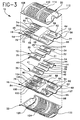
- FIG. 3 is an exploded perspective view of the muffler shown in FIG. 1 and 2.
- FIG. 4 is a cross-sectional view taken along line 4-4 in FIG. 2.
- FIG. 5 is a cross-sectional view taken along line 5-5 in FIG. 4.
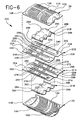
- FIG. 6 is an exploded perspective view of an alternate muffler having an external appearance identical to the muffler shown in FIGS. 1 and 2.
- FIG. 7 is a cross-sectional view similar to FIG. 4, but showing the muffler of FIG. 6.
- FIG. 8 is a cross-sectional view similar to FIG. 5, but showing the muffler of FIG. 6.
- a muffler in accordance with the subject invention is identified generally by the numeral 10 in FIGS. 1-5. As shown most clearly in FIG. 3, the muffler 10 includes first and second flow channelizing sheets 12 and 14, first and second internal plates 16 and 18 and first and second external shells 20 and 22.
- the first and second sheets 12 and 14 are formed by stamp forming, roll forming or other known metal forming techniques to define a plurality of channels. More particularly, the first sheet 12 includes a pair of coplanar peripheral flanges 24 and 26 and first, second and third channels 28, 30 and 32 which are separated from one another by planar portions 29 and 31 respectively.
- the second sheet 14 similarly is characterized by a pair of coplanar peripheral flanges 34 and 36.
- First through third parallel channels 38, 40 and 42 are formed in the second sheet 14 between the peripheral flanges 34 and 36, and are separated from one another by planar portions 39 and 41.
- the channels 38, 40 and 42 of the second sheet 14 are formed to register with the channels 28, 30 and 32 respectively of the first sheet 12.
- the coplanar peripheral flanges 24 and 26 of the first sheet 12 will register with the coplanar peripheral flanges 34 and 36 of the second sheet 14. Additionally, the planar portions 29 and 31 of the first sheet will register respectively with the planar portions 39 and 40 of the second sheet.
- the first and second sheets 12 and 14 are provided with perforations 44 in the channels 28, 30, 38 and 40.
- perforations 44 are depicted as being circular apertures, other configurations may be provided to achieve a desired acoustical effect. For example, slots, louvers or large cut-outs may be provided.
- the channels 32 and 42 of the sheets are free of perforations.
- the sheets 12 and 14 are secured to one another to define a tri-flow insert 46.
- Secure connection of the first sheet 12 to the second sheet 14 may be achieved by welding the peripheral flanges 24 and 26 of the first sheet 12 to the corresponding peripheral flanges 34 and 36 of the second sheet 14. Additionally, spot welds, rivets or crimping may be used to secure the planar portions 29 and 31 of the first sheet 12 to the registered planar portions 39 and 41 of the second sheet 14.
- the first internal plate 16 is generally rectangular and includes opposed upstream and downstream ends 48 and 50 and opposed sides 52 and 54.
- the sides 52 and 54 define a width for the internal plate 16 which exceeds the width of the sheets 12 and 14.
- the first internal plate 16 is formed to include an insert seat 56 for receiving the first sheet 12 of the tri-flow insert 46. Portions of the first internal plate 16 within the bounds of the insert seat 56 are formed to define an internal chamber 58 which is cross-sectionally larger than the cross-section of the tri-flow insert 46.
- the first internal plate 16 is further formed to define an inlet channel 60 extending from the upstream end 48 into the region defined by the insert seat 56. Apertures 61 are formed in the inlet channel of the first internal plate 16.
- a downstream tuning channel 62 is generally aligned with the inlet channel 60 and extends from the insert seat 56 toward the downstream end 50.
- the downstream tuning channel 62 terminates in an aperture 64 for communication with a low frequency resonating chamber as explained below.
- other aperture such as an array of perforations, louvers or the like, means may be provided for permitting the expansion and/or cross flow of exhaust gas.
- a downstream return channel 66 extends from a location near the downstream end 50 of the first internal plate 16 back to the insert seat 56.
- the downstream return channel 66 is depicted as being free of apertures in this embodiment. However, apertures may be provided in other embodiments for permitting an in-flow of exhaust gas.
- An upstream flow channel 70 is generally aligned with the downstream return channel 66 and extends from the insert seat 56 toward the upstream end 48 of the first internal plate 16.
- the upstream flow channel 70 is characterized by apertures 72 for permitting expansion of exhaust gas.
- other means can be provided for permitting expansion of exhaust gas from the upstream flow channel 70.
- An upstream return channel 74 extends from a location near the upstream end 48 of the first internal plate 16 to the insert seat 56.
- the upstream return channel 74 includes apertures 76 for permitting an in-flow of exhaust gas.
- An outlet channel 77 is aligned with the upstream return channel 74 and extends from the insert seat 56 to the downstream end 50 of the first internal plate 16. The outlet channel 77 is free of apertures.
- the second internal plate 18 is generally a mirror image of the first internal plate 16. More particularly, the second internal plate 18 includes an inlet end 78, an outlet end 80 and opposed sides 82 and 84 which will register with the corresponding ends and sides of the first internal plate 16 upon assembly of the muffler, as explained further herein.
- the second internal plate 18 further includes an insert seat 86 for receiving the second sheet 14 of the tri-flow insert 46.
- the insert seat 86 is characterized by an internal chamber 88 which is cross-sectionally larger than the cross-section of the tri-flow insert 46.
- the second internal plate 18 includes an inlet channel 90 which extends from the inlet end 78 to the insert seat 86.
- the inlet channel 90 is disposed to register with the inlet channel 60 of the first internal plate 16.
- Apertures 91 extend through the inlet channel 90.
- a downstream flow channel 92 is aligned with the inlet channel 90 and extends from the insert seat 86 toward the downstream end 80 of the second internal plate 18.
- the downstream flow channel 92 includes an aperture 94 intermediate the length of the channel for permitting expansion of exhaust gas therefrom.
- the downstream flow channels 62 and 92 of the first and second internal plates 16 and 18 register with one another. However the apertures 64 and 94 are not registered.
- a downstream return channel 96 extends from a location near the downstream end 80 of the second internal plate 18 to the insert seat 86.
- the downstream return channel 96 is characterized by an aperture 98 to permit an in-flow of exhaust gas, and is disposed to register with the corresponding channel 66 of the first internal plate 16.
- An upstream flow channel 100 is aligned with the downstream return channel 96 and extends from the insert seat 86 toward the upstream end 78 of the second internal plate 18.
- the upstream flow channel 100 is characterized by apertures 102 to permit expansion of exhaust gas.
- An upstream return channel 104 extends from a location near the upstream end 78 of the second internal plate 18 to the insert seat 86.
- the upstream return channel 104 includes apertures 106 for permitting an in-flow of exhaust gas.
- the upstream flow channel 100 and the upstream return channel 104 are disposed to register respectively with the channels 70 and 74 of the first internal plate 16.
- An outlet channel 107 is aligned with the upstream return channel 104 and extends from the insert seat 86 to the outlet end 80 of the second internal plate 18.
- the outlet channel 107 is disposed to register with the outlet channel 77 of the first internal plate 16 and is free of apertures.
- the first external shell 20 is generally rectangular and includes a peripheral flange 108 dimensioned to register with peripheral regions of the first internal plate 16.
- the first external shell is formed to include first and second chambers 110 and 112 extending from the peripheral flange 108 and separated from one another by a connecting portion 114.
- the second external shell 22 includes a peripheral flange 118 disposed to register with the peripheral flange 108 of the first external shell 20. Additionally, the second external shell 22 includes first and second chambers 120 and 122 extending from the peripheral flange 118 and a connecting portion 124 therebetween.
- the peripheral flanges 108 and 118 of the first and second external shells 20 and 22 are formed with arcuate regions to surround and engage portions of the inlet channels 60, 90 and the outlet channels 77, 107.
- the muffler 10 is assembled by securing the sheets 12 and 14 together to define a tri-flow insert 46.
- the sheets 12 and 14 preferably are connected by welding, but other methods of connection are acceptable.
- the first and second internal plates 16 and 18 are then secured around the insert 46, such that the insert 46 is securely positioned in the insert seats 56 and 86 of the first and second internal plates 16 and 18 respectively.
- the first and second internal plates 16 and 18 may be spot welded to one another at locations intermediate the respective channels and may further be spot welded to one end of the insert 46. Securing only one end of the insert 46 permits thermal expansion to occur without damaging the connections or deforming the parts.
- the insert 46 with the internal plates 16 and 18 sandwiched thereabout may then be placed intermediate the first and second external shells 20 and 22.
- Selected locations on the connecting portions 114 and 124 of the external shells 20 and 22 may be spot welded to opposed regions of the internal chambers 58 and 88 of the first and second internal plates 16 and 18.
- the peripheral flanges 108 and 118 of the first and second external shells 20 and 22 may then be laser welded to the peripheral regions of the first and second internal plates 16 and 18.
- This laser welding preferably defines a continuous integral seam joining the peripheral flanges 108 and 118 and peripheral regions of the first and second internal plates 16 and 18.
- Other connection techniques may be employed, such as welding with other apparatus or crimping.
- the channels of the first and second internal plates register with one another to define tubes for carrying exhaust gas.
- Each of the tubes defined by the internal plates 16 and 18 communicates with the gas passages defined by the channels in the sheets 12 and 14 defining the tri-flow insert 46.
- the gas passages defined by the tri-flow insert all bridge the internal chamber 58, 88 formed by the internal plates 16 and 18 to provide communication between the aligned tubes on opposite sides of the insert seats 56, 86.
- the external chambers 110, 120, 112 and 122 of the external shells 20 and 22 surround portions of the tubes defined by the internal plates 16 and 18.
- the upstream external chambers 110 and 120 are separated from the downstream external chambers 112 and 122 by the internal chamber 58, 88.
- the internal chamber 58, 88 functions as a baffle which separates the upstream and downstream external chambers from one another.
- the exhaust gas continues through the inlet tube and into the first gas passage defined by the first channels 28 and 38 of the insert 46. Some of this exhaust gas in the first gas passage 28, 38 will expand through apertures 44 of the tri-flow insert 46 and into the internal chamber 58, 88. However, a significant portion of the exhaust gas will continue through the tri-flow insert 46 and into the downstream flow tube defined by channels 62 and 92. This exhaust gas will expand through the aperture 94 and into the downstream external chamber 122. Portions of the tube formed by the channels 62 and 92 downstream from the aperture 94 will function as a tuning tube.
- the tuning tube defined by these downstream ends of channels 62 and 92 will communicate with the downstream external chamber 112 through the aperture 64.
- the downstream external chamber 112 functions as a Helmholz or low frequency resonating chamber that will attenuate a narrow range of low frequency noise that may not be adequately attenuated by other parts of the muffler 10.
- the particular frequency that will be attenuated will depend upon the volume of the chamber 112, the cross-sectional area of the tube formed by the channels 62 and 92 and the distance between the apertures 64 and 94. In some embodiments, effects of a Helmholz chamber can be achieved even with the apertures 64 and 94 being registered.
- Exhaust gas expanding through the aperture 94 and into the downstream external chamber 122 will flow through the aperture 98 and into the downstream return tube formed by channels 66 and 96. This exhaust gas will continue in an upstream direction and into the second gas passage defined by the second channels 30 and 40 of the insert 46.
- the apertures 44 in the channels 30 and 40 permit a cross-flow of exhaust gas between the internal chamber 58, 88 and the second gas passage 30, 40 of the tri-flow insert 46.
- Exhaust gas will continue from the insert 46 into the upstream flow tube defined by channels 70 and 100 of the first and second internal plates 16 and 18 respectively. This exhaust gas will be permitted to expand through apertures 72 and 102 and into the upstream external chambers 110 and 120.
- Exhaust gas will continue into the apertures 76 and 106 of the upstream return tube defined by channels 74 and 104, and into the third gas passage defined by the third channels 32 and 42 of the tri-flow insert 46. Exhaust gas will continue to the outlet tube defined by outlet channels 77 and 107.
- FIGS. 6-8 A muffler with an alternate internal construction is illustrated in FIGS. 6-8, and is identified generally by the numeral 210.
- the muffler 210 includes first and second external shells 20 and 22 which are identical to those on the muffler 10 described and illustrated above.
- the muffler 210 also includes first and second internal plates 212 and 214, and first and second baffle sheets 216 and 218.
- the first internal plate 212 is generally rectangular and includes an upstream end 224, a downstream end 226 and opposed sides 228 and 230 defining a width "W".
- the first internal plate 212 is formed to define generally parallel channels 232, 234 and 236.
- the channel 232 is in proximity to the side 228 of the first internal plate 212 and extends from the upstream end 224 to a location near the downstream end 226.
- the channel 234 is generally adjacent the side 230 of the first internal plate 212 and extends from a location near the downstream end 226 to a location near the upstream end 224.
- the channel 236 is disposed intermediate the channels 232 and 234 and extends from a location near the upstream end 224 entirely to the downstream end 226.
- the channels 232, 234 and 236 have perforations to enable a controlled expansion and/or cross-flow of exhaust gas.
- the channel 232 includes a first array of perforations 238 near the upstream end 224, a second array of perforations 240 intermediate the opposed ends 224 and 226 and a single aperture 242 at the downstream end of the channel 232.
- the channel 234 is substantially free of apertures near its downstream end, but includes an array of apertures 246 at an intermediate location and a second array of apertures 248 near the upstream end.
- the channel 236 is provided with an array of apertures 250 near the upstream end, but is substantially free of apertures along the remainder of the channel 236 entirely to the downstream end 226 of the first internal plate 212.
- the second internal plate 214 is structurally and dimensionally similar to the first internal plate 212. More particularly, the second internal plate 214 includes an upstream end 254, a downstream end 256 and opposed sides 258 and 260.
- the second internal plate 214 includes generally parallel longitudinally extending channels 262, 264 and 266 which are disposed and dimensioned to register respectively with the channels 232, 234 and 236 of the first internal plate 212.
- the channel 262 extends from the upstream end 254 of the second internal plate 214 to a location near the downstream end 214.
- the channel 262 includes an array of perforations 268 near the upstream end, a second array of perforations 270 intermediate the opposed ends and a cut-out 272 between the downstream end of channel 262 and the array of perforations 270.
- the channel 264 is generally adjacent the side 260 of the second internal plate 214 and includes a cut-out 274 near the downstream end 256 of the second internal plate 214.
- the channel 264 further includes an array of perforations 276 intermediate the opposed ends of the channel 264 and a second array of perforations 278 near the upstream end 254 of the second internal plate 214.
- the channel 266 is disposed intermediate the channels 262 and 264 and extends from a location near the upstream end 254 of the second internal plate 214 entirely to the downstream end 256 thereof.
- the channel 266 includes an array of perforations 280 near the upstream end 254.
- the first baffle sheet 216 includes an upstream end 284, a downstream end 286 and opposed sides 288 and 290 which define a width "w" which is less than the width "W" of the internal plates 212 and 214.
- the sides 288 and 290 of the first baffle sheet 216 define peripheral flanges dimensioned to engage portions of the first internal plate 212 between the channels 232 and 234 and the respective sides 228 and 230.
- the upstream end 284 of the baffle sheet 216 is characterized by arcuate tube mounting portions dimensioned and disposed for nesting with the channels 232, 234 and 236 of the first internal plate 212.
- the downstream end 286 is provided with a similar array of arcuate portions for nesting respectively with the channels of the first internal plate 212.
- a baffle chamber 292 is defined between the opposed ends 284 and 286 of the first baffle sheet 216. As explained further herein, the baffle chamber 292 is dimensioned and configured to surround portions of the channels 232, 234 and 236 and to engage opposed portions of the first external shell 20.
- the second baffle sheet 218 is dimensionally and structurally similar to the first baffle sheet 216. More particularly, the second baffle sheet 218 includes opposed upstream and downstream ends 294 and 296 and opposed sides 298 and 300. The sides 298 and 300 define a width "w" approximately equal to the width "w" of the first baffle sheet 216. Additionally, portions of the second baffle sheet 218 adjacent the sides 298 and 300 form substantially coplanar flanges dimensioned for engagement at locations on the second internal plate 214 between the channels 262 and 264 and the respective sides 258 and 260 of the second internal plate 214.
- the upstream and downstream ends 294 and 296 of the second baffle sheet 218 are formed with arcuate portions disposed and dimensioned for tight nesting engagement with the channels 262, 264 and 266 of the second internal plate 214.
- the second baffle sheet 218 further is formed to define a baffle chamber 302.
- the muffler 210 is assembled by initially securing the first internal plate 212 in face to face relationship with the second internal plate 214 such that peripheral regions of the plates 212 and 214 are substantially registered. Additionally, the channels 232, 234 and 236 of the first internal plate 212 will register respectively with the channels 262, 264 and 266 of the second internal plate 214 to define an array of substantially parallel tubes.
- Assembly of the muffler 10 proceeds by securing the first and second baffle sheets 216 and 218 to the first and second internal plates 212 and 214 respectively.
- the first baffle sheet 216 is mounted to the first internal plate 212 such that the baffle chamber 292 encloses the perforations 240 and 246 in the channels 232 and 234 respectively. In this position, the arcuate portions at the upstream and downstream ends 284 and 286 of the baffle sheet 216 will nest tightly with the channels 232, 234 and 236 of the first internal plate 212.
- the second baffle sheet 218 is mounted to the second internal plate 214 such that the baffle chamber 302 encloses the perforations 270 and 276 in the channels 262 and 264 respectively. In this position, the arcuate portions at the upstream and downstream ends 294 and 296 of the second baffle sheet 218 will nest closely with the channels 262, 264 and 266 of the second internal plate 214.
- Assembly of the muffler 10 proceeds by securing the first and second external shells 20 and 22 around the assembly of the first and second internal plates 212 and 214 and the first and second baffle sheets 216 and 218.
- peripheral flanges 108 and 118 of the first and second external shells 20 and 22 will register respectively with one another and with peripheral regions of the internal plates 212 and 214.
- the connecting portion 114 of the first external shell 20 will engage the baffled chamber 292 of the baffle sheet 216
- the connecting portion 124 of the second external shell 22 will engage the baffle chamber 302 of the second baffle sheet 216.
- the upstream chamber 110 of the first external shell 20 will be separated from the downstream chamber 112 by the baffle chamber 292 of the baffle sheet 216. Additionally, the upstream chamber 110 will surround the perforation arrays 238, 248 and 250 near the upstream end 224 of the first internal plate 212. Additionally, the downstream chamber 112 of the first external shell 20 will surround the aperture 242 near the downstream end of the channel 232. In a similar manner, the upstream chamber 120 of the second external shell 22 will surround the perforation arrays 268, 278 and 280 near the upstream end 254 of the second internal plate 214. Additionally, the downstream chamber 122 will surround and enclose the apertures 272 and 274 in the channels 262 and 264 near the downstream end 256 of the second internal plate 214.
- the muffler 210 functions exactly as the muffler 10 described and illustrated above, and includes the same general gas flow path. The only difference between the muffler 10 and the muffler 210 relates to the relative position of the sheets within the muffler. More particularly, the sheets 12 and 14 of the muffler 10 are disposed between the internal plates 16 and 18, and are formed to define tubes that bridge the internal chamber 58, 88 stamp formed in the internal plates 16 and 18. Conversely, the sheets 216 and 218 of the muffler 210 are disposed between the internal plates and the corresponding external shell.
- the muffler 210 offers some manufacturing and engineering efficiencies. For example, the draws of metal in the internal plates are substantially shallower and less complex.
- the muffler 210 permits the dimensions of the upstream and downstream chambers to be varied without a complete redesign of the internal plates.
- the sheets defining the baffle chambers of the muffler 210 need merely be moved longitudinally along the internal plates to change the relative dimensions of the upstream and downstream chambers. Redesigns of this type could only require a different array of apertures in the internal plates and perhaps a corresponding change to the location of the connecting portion on each external shell.
- the mufflers 10 and 210 provide several significant efficiencies.
- the muffler 10 and 210 provide at least one low frequency resonating chamber, at least one high frequency tuning chamber and a plurality of expansion chambers with only six simply formed components that can be assembled in a highly automated environment.
- This basic design offers options for several modifications.
- either of the upstream external chambers 110, 120 may function as a second low frequency resonating chamber by providing communication through only one of the formed tubes.
- the relative dimensions of any of the chambers can be varied easily by either changing the shape of the external shells 20, 22 or by changing the relative positions of the internal baffle chambers.
- the degree of communication between the formed tubes and the chambers can be altered by merely changing the size, shapes and locations of the apertures through the tubes.
- Very simple mufflers with this basic design can be developed by eliminating an external shell so that one of the plates and the associated baffle shell define exterior portions of the muffler. In this latter embodiment, the exteriorly disposed plate would be free of apertures.
- Other simplifications may include removing one of the baffle shells so that a much larger expansion chamber is provided between one of the internal plates and the opposed external shell 20.
Description
- 1. Field of the Invention. The subject invention relates to an exhaust muffler manufactured from formed components. The muffler provides several acoustical tuning options for efficiently attenuating the noise associated with the flow of exhaust gas.
- 2. Description of the Prior Art. The most commonly used prior art exhaust muffler includes a plurality of separate parallel tubes that are supported by transversely extending planar baffles of oval or circular shape. The assembly of tubes and baffles is slid into a tubular shell that has a cross-sectional configuration conforming to the shape of the baffles. An outer wrapper may be wrapped around the shell for additional strength and noise insulation. Opposed end caps or headers are then mechanically connected to the opposed ends of the shell and wrapper to enclose the muffler. Each end cap includes an aperture to define an inlet to or outlet from the muffler. With this construction, chambers are defined within the prior art muffler between adjacent baffles or between a baffle and an end cap. Each chamber is enclosed by the tubular outer shell. Some of the tubes in the prior art muffler may terminate in a chamber. Others will pass entirely through a chamber. Portions of tubes in certain chambers will have louvers or perforations to permit gas communication between the tube and the surrounding chamber.
- Exhaust gas in the above described prior art muffler flows from tubes into the surrounding chambers and from the chambers into other tubes. The particular pattern of exhaust gas flow will vary from one muffler design to another. However, many prior art mufflers utilize a tri-flow pattern. Exhaust gas enters the upstream end of a tri-flow muffler and flows to a reversing chamber near the opposed downstream end. The exhaust gas then undergoes a substantially 180° change in direction and flows back toward the upstream end of the muffler to a second reversing chamber. The exhaust gas then undergoes a second 180° change in direction and continues from the second reversing chamber to the outlet at the downstream end of the muffler. Perforated portions of the tubes pass through expansion chambers in the prior art muffler to permit expansion and cross flow of exhaust gas and to achieve attenuation of a major portion of the noise. Some non-perforated tubes may dead end into an enclosed Helmholz chamber to attenuate any narrow range of low frequency noise that is not adequately attenuated by the expansion chamber. The acoustical performance of this prior art muffler can be changed considerably by varying the dimensions of the tubes and chambers and by changing the size and locations of apertures, louvers or the like.
- The above described prior art muffler is effective in attenuating noise. However, these prior art mufflers require a large number of separate components that must be assembled in a labor intensive manufacturing process. Furthermore, the abrupt edges of the tubes and the right angle alignment of the outer shell to the baffles, contribute to turbulence and back pressure that can impede engine performance.
- The prior art also includes mufflers made entirely or substantially from formed sheets of metal. Very effective prior art formed mufflers are shown in patents assigned to the assignee of the subject invention. Most of these prior art formed mufflers include a pair of plates that are stamp formed with channels. The plates are secured in opposed face-to-face relationship, such that the channels define gas passages or tubes between the plates. These prior art stamp formed mufflers further include at least one external shell secured to at least one of the plates to define at least one chamber surrounding the gas passages or tubes formed by the plates. The tubes may be perforated to provide gas communication with the chambers defined by the external shell. These prior art stamp formed mufflers are shown in U.S. Patent No. PE 33,370 and Reexamined U.S. Patent No. 4,736,817.
- Further improvements to stamp formed mufflers are shown in U.S. Patent No. 5,252,788 which also is assigned to the assignee of the subject invention. The plates of the muffler shown in U.S. Patent No. 5,252,788 are formed to define tubes and to further define an in-line chamber. The in-line chamber is bridged by a conventional tube disposed at a central location between the respective sides of the muffler. Exhaust gas entering this prior art muffler will flow through a formed inlet tube and will expand into the in-line chamber formed between the plates. The exhaust gas will then flow around opposite respective sides of the conventional tube and will expand a second time into portions of the in-line chamber downstream from the conventional tube. The exhaust gas will then enter a formed flow tube that communicates with the in-line chamber. The flow tube may be perforated or louvered to permit expansion of exhaust gas into a chamber defined by the external shell. The exhaust gas will continue into a second flow tube which communicates with the conventional tube that bridges the in-line chamber. Exhaust gas will continue through the conventional tube and toward the outlet of this prior art muffler. The in-line chamber formed by the plates extends into contact with the external shell of the muffler shown in U.S. Patent No. 5,252,788. Thus, the in-line chamber can effectively function as a baffle between spaced apart chambers defined by the external shell.
- This prior art muffler known from the US 5,252,788 has proved to be very effective and has been widely commercialized. However, it is desirable to provide even more tuning options in a muffler, which cannot be achieved by the prior art muffler as possible changes in the design are limited or difficult to be carried out.
- It is the object of the invention to provide a muffler with more tuning options entirely made from formed components and having enhanced acoustical tuning capabilities.
- This object is fulfilled by a muffler having the features disclosed in claim 1. Preferred embodiments are defined in the subclaims.
- The subject invention is directed to a muffler manufactured from formed sheets of metal. Each sheet preferably is formed by stamping. However, metal forming techniques that rely upon hydraulic forces, magnetic forces and/or explosive forces also can be used for manufacturing at least certain of the components of the muffler.
- The muffler of the subject invention includes first and second plates formed to define a plurality of channels. The plates are secured in face-to-face relationship such that the channels define tubes. Channels in one plate preferably register with channels in the other plate, but extend in opposite directions. Thus tubes of generally oval or circular cross-sectional shape are defined. At least two tubes extend to the periphery of the plates and define at least one inlet and at least one outlet for the muffler. Selected portions of the formed tubes are provided with aperture means for permitting communication of exhaust gas between the tubes and surrounding regions of the muffler.
- The muffler further includes a formed sheet secured to the first plate. The sheet and the plates are formed to define an internal chamber with a plurality of formed tubes passing therethrough. At least one tube passing through the internal chamber includes aperture means for permitting communication of exhaust gas between the internal chamber and the formed tubes passing therethrough. Tubes passing through the internal chamber communicate with other tubes formed by the first and second plates, and hence also communicate with the inlet and outlet of the muffler. In preferred embodiments, as explained further herein, first and second formed sheets are secured respectively to the first and second plates to define an internal chamber that surrounds tubes passing therethrough.
- The relationship of the formed sheets and the plates relative to one another may differ from one embodiment of the muffler to the next. For example, the internal chamber may be formed by the plates. In this embodiment, the sheets may be secured in face-to-face relationship with one another and may be formed to define a plurality of tubes therebetween. These interconnected sheets define a flow channelizing insert that may be secured between the plates of the muffler to bridge the internal chamber formed by the plates. Selected tubes of the insert may be provided with aperture means for permitting communication of exhaust gas between the tubes of the insert and the internal chamber defined by the plates.
- In an alternate embodiment the sheets may be formed to define the internal chamber of the muffler. The sheets may further be formed to closely surround portions of the tubes defined by the plates. These portions of the internal plates surrounded by the formed sheets may have aperture means for permitting gas communication between the tubes and the internal chamber.
- The muffler of the subject invention further includes at least one external shell, and preferably a pair of external shells. The external shell is securely connected to a formed plate and defines at least one chamber that surrounds the tubes formed in the plate. Additionally, portions of the external shell are formed to engage the internal chamber defined either by the corresponding formed plate or the sheet. Thus, the internal chamber forms a baffle which separates chambers defined by the corresponding external shell. The external shell is further formed to define inlet and outlet openings for surrounding the inlet and outlet tubes defined by the plates.
- Exhaust gas entering the muffler of the subject invention will flow through an inlet tube defined by the formed plates of the muffler. The exhaust gas will continue through a first tube which bridges the internal chamber. Apertures may be provided for permitting expansion of exhaust gas into the internal chamber. Exhaust gas may next flow into a tube formed by the plates and located downstream of the internal chamber. This downstream tube may include an aperture or perforations to permit exhaust gas to flow into a downstream chamber defined by at least one external shell. A downstream return tube formed by the plates may have communication means for receiving exhaust gas from the downstream chamber and may direct the exhaust gas back through a tube that bridges the internal chamber. Apertures, perforations or the like may permit further gas communication with the internal chamber. Exhaust gas may continue upstream through a tube which includes aperture means for communicating with an upstream chamber defined by the external shell. The upstream chamber may be separated from the downstream chamber by the internal chamber. An upstream return tube formed by the plates may receive exhaust gas from the upstream chamber, and may direct the exhaust gas through the internal chamber, and to an outlet of the muffler.
- Considerable variations of this basic design can be provided so that the muffler can be tuned to the acoustical needs of a particular exhaust system. For example, the internal chamber can function as a reversing chamber, and the downstream chamber can function as at least one Helmholz chamber for attenuating selected narrow ranges of low frequency noise. In other embodiments, one external shell and one internal plate may form a Helmholz chamber, while the other external shell and the other plate may form an expansion or reversing chamber. In all such embodiments, the acoustical tuning can be varied by changing the location, size and shape of aperture means in the formed tubes of the plates and the gas passages of the insert.
- FIG. 1 is a perspective view of a muffler in accordance with the subject invention.
- FIG. 2 is a bottom plan view of the muffler shown in FIG. 1.
- FIG. 3 is an exploded perspective view of the muffler shown in FIG. 1 and 2.
- FIG. 4 is a cross-sectional view taken along line 4-4 in FIG. 2.
- FIG. 5 is a cross-sectional view taken along line 5-5 in FIG. 4.
- FIG. 6 is an exploded perspective view of an alternate muffler having an external appearance identical to the muffler shown in FIGS. 1 and 2.
- FIG. 7 is a cross-sectional view similar to FIG. 4, but showing the muffler of FIG. 6.
- FIG. 8 is a cross-sectional view similar to FIG. 5, but showing the muffler of FIG. 6.
- A muffler in accordance with the subject invention is identified generally by the numeral 10 in FIGS. 1-5. As shown most clearly in FIG. 3, the
muffler 10 includes first and secondflow channelizing sheets internal plates external shells - The first and
second sheets first sheet 12 includes a pair of coplanarperipheral flanges third channels planar portions second sheet 14 similarly is characterized by a pair of coplanarperipheral flanges parallel channels second sheet 14 between theperipheral flanges planar portions channels second sheet 14 are formed to register with thechannels first sheet 12. In this registered condition, the coplanarperipheral flanges first sheet 12 will register with the coplanarperipheral flanges second sheet 14. Additionally, theplanar portions planar portions - The first and
second sheets perforations 44 in thechannels perforations 44 are depicted as being circular apertures, other configurations may be provided to achieve a desired acoustical effect. For example, slots, louvers or large cut-outs may be provided. Thechannels - The
sheets tri-flow insert 46. Secure connection of thefirst sheet 12 to thesecond sheet 14 may be achieved by welding theperipheral flanges first sheet 12 to the correspondingperipheral flanges second sheet 14. Additionally, spot welds, rivets or crimping may be used to secure theplanar portions first sheet 12 to the registeredplanar portions second sheet 14. - The first
internal plate 16 is generally rectangular and includes opposed upstream and downstream ends 48 and 50 and opposedsides sides internal plate 16 which exceeds the width of thesheets - The first
internal plate 16 is formed to include aninsert seat 56 for receiving thefirst sheet 12 of thetri-flow insert 46. Portions of the firstinternal plate 16 within the bounds of theinsert seat 56 are formed to define aninternal chamber 58 which is cross-sectionally larger than the cross-section of thetri-flow insert 46. - The first
internal plate 16 is further formed to define aninlet channel 60 extending from theupstream end 48 into the region defined by theinsert seat 56.Apertures 61 are formed in the inlet channel of the firstinternal plate 16. Adownstream tuning channel 62 is generally aligned with theinlet channel 60 and extends from theinsert seat 56 toward thedownstream end 50. Thedownstream tuning channel 62 terminates in anaperture 64 for communication with a low frequency resonating chamber as explained below. However, other aperture, such as an array of perforations, louvers or the like, means may be provided for permitting the expansion and/or cross flow of exhaust gas. - A
downstream return channel 66 extends from a location near thedownstream end 50 of the firstinternal plate 16 back to theinsert seat 56. Thedownstream return channel 66 is depicted as being free of apertures in this embodiment. However, apertures may be provided in other embodiments for permitting an in-flow of exhaust gas. - An upstream flow channel 70 is generally aligned with the
downstream return channel 66 and extends from theinsert seat 56 toward theupstream end 48 of the firstinternal plate 16. The upstream flow channel 70 is characterized byapertures 72 for permitting expansion of exhaust gas. As noted above, other means can be provided for permitting expansion of exhaust gas from the upstream flow channel 70. - An
upstream return channel 74 extends from a location near theupstream end 48 of the firstinternal plate 16 to theinsert seat 56. Theupstream return channel 74 includes apertures 76 for permitting an in-flow of exhaust gas. Anoutlet channel 77 is aligned with theupstream return channel 74 and extends from theinsert seat 56 to thedownstream end 50 of the firstinternal plate 16. Theoutlet channel 77 is free of apertures. - The second
internal plate 18 is generally a mirror image of the firstinternal plate 16. More particularly, the secondinternal plate 18 includes aninlet end 78, anoutlet end 80 and opposedsides internal plate 16 upon assembly of the muffler, as explained further herein. The secondinternal plate 18 further includes aninsert seat 86 for receiving thesecond sheet 14 of thetri-flow insert 46. Theinsert seat 86 is characterized by aninternal chamber 88 which is cross-sectionally larger than the cross-section of thetri-flow insert 46. - The second
internal plate 18 includes aninlet channel 90 which extends from theinlet end 78 to theinsert seat 86. Theinlet channel 90 is disposed to register with theinlet channel 60 of the firstinternal plate 16.Apertures 91 extend through theinlet channel 90. Adownstream flow channel 92 is aligned with theinlet channel 90 and extends from theinsert seat 86 toward thedownstream end 80 of the secondinternal plate 18. Thedownstream flow channel 92 includes anaperture 94 intermediate the length of the channel for permitting expansion of exhaust gas therefrom. Thedownstream flow channels internal plates apertures - A
downstream return channel 96 extends from a location near thedownstream end 80 of the secondinternal plate 18 to theinsert seat 86. Thedownstream return channel 96 is characterized by anaperture 98 to permit an in-flow of exhaust gas, and is disposed to register with the correspondingchannel 66 of the firstinternal plate 16. - An
upstream flow channel 100 is aligned with thedownstream return channel 96 and extends from theinsert seat 86 toward theupstream end 78 of the secondinternal plate 18. Theupstream flow channel 100 is characterized byapertures 102 to permit expansion of exhaust gas. Anupstream return channel 104 extends from a location near theupstream end 78 of the secondinternal plate 18 to theinsert seat 86. Theupstream return channel 104 includesapertures 106 for permitting an in-flow of exhaust gas. Theupstream flow channel 100 and theupstream return channel 104 are disposed to register respectively with thechannels 70 and 74 of the firstinternal plate 16. - An
outlet channel 107 is aligned with theupstream return channel 104 and extends from theinsert seat 86 to the outlet end 80 of the secondinternal plate 18. Theoutlet channel 107 is disposed to register with theoutlet channel 77 of the firstinternal plate 16 and is free of apertures. - The first
external shell 20 is generally rectangular and includes aperipheral flange 108 dimensioned to register with peripheral regions of the firstinternal plate 16. The first external shell is formed to include first andsecond chambers peripheral flange 108 and separated from one another by a connectingportion 114. The secondexternal shell 22 includes aperipheral flange 118 disposed to register with theperipheral flange 108 of the firstexternal shell 20. Additionally, the secondexternal shell 22 includes first andsecond chambers peripheral flange 118 and a connectingportion 124 therebetween. Theperipheral flanges external shells inlet channels outlet channels - The
muffler 10 is assembled by securing thesheets tri-flow insert 46. Thesheets internal plates insert 46, such that theinsert 46 is securely positioned in the insert seats 56 and 86 of the first and secondinternal plates internal plates insert 46. Securing only one end of theinsert 46 permits thermal expansion to occur without damaging the connections or deforming the parts. Theinsert 46 with theinternal plates external shells portions external shells internal chambers internal plates peripheral flanges external shells internal plates peripheral flanges internal plates - In this interconnected state, the channels of the first and second internal plates register with one another to define tubes for carrying exhaust gas. Each of the tubes defined by the
internal plates sheets tri-flow insert 46. Additionally, the gas passages defined by the tri-flow insert all bridge theinternal chamber internal plates external chambers external shells internal plates external chambers external chambers internal chamber internal chamber - Exhaust gas enters the
muffler 10 at the inlet tube defined by theinlet channels internal plates first channels insert 46. Some of this exhaust gas in thefirst gas passage apertures 44 of thetri-flow insert 46 and into theinternal chamber tri-flow insert 46 and into the downstream flow tube defined bychannels aperture 94 and into the downstreamexternal chamber 122. Portions of the tube formed by thechannels aperture 94 will function as a tuning tube. The tuning tube defined by these downstream ends ofchannels external chamber 112 through theaperture 64. Thus, the downstreamexternal chamber 112 functions as a Helmholz or low frequency resonating chamber that will attenuate a narrow range of low frequency noise that may not be adequately attenuated by other parts of themuffler 10. The particular frequency that will be attenuated will depend upon the volume of thechamber 112, the cross-sectional area of the tube formed by thechannels apertures apertures - Exhaust gas expanding through the
aperture 94 and into the downstreamexternal chamber 122 will flow through theaperture 98 and into the downstream return tube formed bychannels second channels insert 46. Theapertures 44 in thechannels internal chamber second gas passage tri-flow insert 46. Exhaust gas will continue from theinsert 46 into the upstream flow tube defined bychannels 70 and 100 of the first and secondinternal plates apertures external chambers apertures 76 and 106 of the upstream return tube defined bychannels third channels tri-flow insert 46. Exhaust gas will continue to the outlet tube defined byoutlet channels - A muffler with an alternate internal construction is illustrated in FIGS. 6-8, and is identified generally by the numeral 210. The
muffler 210 includes first and secondexternal shells muffler 10 described and illustrated above. Themuffler 210 also includes first and secondinternal plates second baffle sheets - The first
internal plate 212 is generally rectangular and includes anupstream end 224, adownstream end 226 and opposedsides internal plate 212 is formed to define generallyparallel channels channel 232 is in proximity to theside 228 of the firstinternal plate 212 and extends from theupstream end 224 to a location near thedownstream end 226. Thechannel 234 is generally adjacent theside 230 of the firstinternal plate 212 and extends from a location near thedownstream end 226 to a location near theupstream end 224. Thechannel 236 is disposed intermediate thechannels upstream end 224 entirely to thedownstream end 226. - The
channels channel 232 includes a first array ofperforations 238 near theupstream end 224, a second array ofperforations 240 intermediate the opposed ends 224 and 226 and asingle aperture 242 at the downstream end of thechannel 232. Thechannel 234 is substantially free of apertures near its downstream end, but includes an array ofapertures 246 at an intermediate location and a second array ofapertures 248 near the upstream end. Thechannel 236 is provided with an array ofapertures 250 near the upstream end, but is substantially free of apertures along the remainder of thechannel 236 entirely to thedownstream end 226 of the firstinternal plate 212. - The second
internal plate 214 is structurally and dimensionally similar to the firstinternal plate 212. More particularly, the secondinternal plate 214 includes anupstream end 254, adownstream end 256 and opposedsides internal plate 214 includes generally parallel longitudinally extendingchannels channels internal plate 212. Thechannel 262 extends from theupstream end 254 of the secondinternal plate 214 to a location near thedownstream end 214. Thechannel 262 includes an array ofperforations 268 near the upstream end, a second array ofperforations 270 intermediate the opposed ends and a cut-out 272 between the downstream end ofchannel 262 and the array ofperforations 270. Thechannel 264 is generally adjacent theside 260 of the secondinternal plate 214 and includes a cut-out 274 near thedownstream end 256 of the secondinternal plate 214. Thechannel 264 further includes an array ofperforations 276 intermediate the opposed ends of thechannel 264 and a second array ofperforations 278 near theupstream end 254 of the secondinternal plate 214. Thechannel 266 is disposed intermediate thechannels upstream end 254 of the secondinternal plate 214 entirely to thedownstream end 256 thereof. Thechannel 266 includes an array ofperforations 280 near theupstream end 254. - The
first baffle sheet 216 includes anupstream end 284, adownstream end 286 and opposedsides internal plates sides first baffle sheet 216 define peripheral flanges dimensioned to engage portions of the firstinternal plate 212 between thechannels respective sides upstream end 284 of thebaffle sheet 216 is characterized by arcuate tube mounting portions dimensioned and disposed for nesting with thechannels internal plate 212. Thedownstream end 286 is provided with a similar array of arcuate portions for nesting respectively with the channels of the firstinternal plate 212. Abaffle chamber 292 is defined between the opposed ends 284 and 286 of thefirst baffle sheet 216. As explained further herein, thebaffle chamber 292 is dimensioned and configured to surround portions of thechannels external shell 20. - The
second baffle sheet 218 is dimensionally and structurally similar to thefirst baffle sheet 216. More particularly, thesecond baffle sheet 218 includes opposed upstream and downstream ends 294 and 296 and opposedsides sides first baffle sheet 216. Additionally, portions of thesecond baffle sheet 218 adjacent thesides internal plate 214 between thechannels respective sides internal plate 214. The upstream and downstream ends 294 and 296 of thesecond baffle sheet 218 are formed with arcuate portions disposed and dimensioned for tight nesting engagement with thechannels internal plate 214. Thesecond baffle sheet 218 further is formed to define abaffle chamber 302. - The
muffler 210 is assembled by initially securing the firstinternal plate 212 in face to face relationship with the secondinternal plate 214 such that peripheral regions of theplates channels internal plate 212 will register respectively with thechannels internal plate 214 to define an array of substantially parallel tubes. - Assembly of the
muffler 10 proceeds by securing the first andsecond baffle sheets internal plates first baffle sheet 216 is mounted to the firstinternal plate 212 such that thebaffle chamber 292 encloses theperforations channels baffle sheet 216 will nest tightly with thechannels internal plate 212. - In a similar manner, the
second baffle sheet 218 is mounted to the secondinternal plate 214 such that thebaffle chamber 302 encloses theperforations channels second baffle sheet 218 will nest closely with thechannels internal plate 214. - Assembly of the
muffler 10 proceeds by securing the first and secondexternal shells internal plates second baffle sheets peripheral flanges external shells internal plates portion 114 of the firstexternal shell 20 will engage thebaffled chamber 292 of thebaffle sheet 216, and the connectingportion 124 of the secondexternal shell 22 will engage thebaffle chamber 302 of thesecond baffle sheet 216. With this construction, theupstream chamber 110 of the firstexternal shell 20 will be separated from thedownstream chamber 112 by thebaffle chamber 292 of thebaffle sheet 216. Additionally, theupstream chamber 110 will surround theperforation arrays upstream end 224 of the firstinternal plate 212. Additionally, thedownstream chamber 112 of the firstexternal shell 20 will surround theaperture 242 near the downstream end of thechannel 232. In a similar manner, theupstream chamber 120 of the secondexternal shell 22 will surround theperforation arrays upstream end 254 of the secondinternal plate 214. Additionally, thedownstream chamber 122 will surround and enclose theapertures channels downstream end 256 of the secondinternal plate 214. - The
muffler 210 functions exactly as themuffler 10 described and illustrated above, and includes the same general gas flow path. The only difference between themuffler 10 and themuffler 210 relates to the relative position of the sheets within the muffler. More particularly, thesheets muffler 10 are disposed between theinternal plates internal chamber internal plates sheets muffler 210 are disposed between the internal plates and the corresponding external shell. Themuffler 210 offers some manufacturing and engineering efficiencies. For example, the draws of metal in the internal plates are substantially shallower and less complex. Additionally, themuffler 210 permits the dimensions of the upstream and downstream chambers to be varied without a complete redesign of the internal plates. In this regard, the sheets defining the baffle chambers of themuffler 210 need merely be moved longitudinally along the internal plates to change the relative dimensions of the upstream and downstream chambers. Redesigns of this type could only require a different array of apertures in the internal plates and perhaps a corresponding change to the location of the connecting portion on each external shell. - The
mufflers muffler external chambers external shells external shell 20. - While the invention has been described with respect to a preferred embodiment, it is apparent that various changes can be made without departing from the scope of the invention as defined by the appended claims.
Claims (10)
- An exhaust muffler (10; 210) comprising:characterized bya first plate (16; 212), a second plate (18; 214) secured in face-to-face relationship with said first plate (16; 212) to form a plurality of tubes as internal gas passages, said tubes including at least one inlet (60, 90) to the muffler and at least one outlet (77, 107) from the muffler, a plurality of said tubes being formed with perforation means (44, 61, 72, 76, 91,102, 106; 240, 238, 246, 248, 250, 270, 268, 276, 278, 280) therethrough for permitting gas communication between said tubes and portions of said muffler (10; 210) surrounding said tubes; andan external shell (20, 22) having a peripheral flange (108, 118) secured to peripheral regions of said first plate (16; 212) and being formed to define at least one external chamber (110, 122) and enclosing and communicating with portions of said tubes formed by said first plate (16; 212),a sheet (12; 216) sized to mate with a portion of said first plate (16; 212) and being spaced from the inlet (60, 90) and the outlet (77, 107),said plates (16, 18; 212, 214) and said sheet (12; 216) being shaped to define at least one internal chamber (58, 88; 292, 302) therebetween, the at least one internal chamber (58, 88; 292, 302) communicating with at least one of the tubes via the perforation means
- The muffler (10; 210) of claim 1, characterized in that said sheet (12; 216) is a first sheet (12; 216) of said muffler, and wherein said muffler (10; 210) further comprises a second sheet (14; 218) secured to said second plate (18; 214), said second sheet (14; 218) being formed to define portions of another internal chamber (58, 88; 292, 302) of said muffler (10; 210).
- The muffler (10; 210) of claim 2, characterized in that said external shell (20, 22) is a first external shell (20), and wherein said muffler (10; 210) further comprises a second external shell (22) having a peripheral flange (118) secured to said second plate (18; 214) and being formed to define at least one external chamber (120, 122) surrounding and secured to portions of said internal chamber (58, 88; 292, 302) and surrounding and communicating with portions of said tubes defined by said second plate (18; 214).
- The muffler of claim 3, characterized in that said first and second plates (16, 18) are formed to define said internal chamber (58, 88), a plurality of said tubes being formed by said first and second plates (16, 18), said first and second sheets (12, 14) being secured in face-to-face relationship with one another and being formed to define a plurality of said tubes of said muffler (10), said first and second sheets (12, 14) being disposed intermediate said first and second plates (16, 18) such that the tubes defined by said first and second sheets (12, 14) extend across said internal chamber (58, 88), at least one tube formed by said first and second sheets (12, 14) being formed with perforation means (44, 61, 72, 76, 91, 102, 106) therein for permitting communication between said tubes formed by said sheets and said internal chamber (58, 88).
- The muffler (210) of claim 3, characterized in that said first and second plates (212, 214) are disposed intermediate said first and second sheets (216, 218), said first and second sheets (216, 218) being formed to define said internal chamber (292, 302) surrounding portions of said tubes formed by said internal plates, portions of said tubes formed by said internal plates having said perforation means (240, 238, 246, 248, 250, 270, 268, 276, 278, 280) disposed within said internal chamber (292, 302).
- The muffler (210) of claim 5, characterized in that said muffler defines an upstream end (224) having said inlet to said muffler (210) and an opposed downstream end (226) having said outlet of said muffler (210) said sheets (216, 218) being secured to said plates (212, 214) at locations intermediate said upstream and downstream ends (224, 226) of said muffler (210) such that said external shells (20, 22) define upstream external chambers (110, 120) between said upstream end (224) and said internal chamber (292, 302) and downstream external chambers (112, 122) between said downstream end (226) and said internal chamber (292, 302).
- The muffler (210) of claim 6, characterized in that said first and second plates (212, 214) are formed to define registered downstream flow channels (232, 262) extending from said internal chamber (292, 302) towards said downstream end (226) of said muffler (210) and registered downstream return channels (234, 264) extending from said internal chamber (292, 302) towards said downstream end (226) of said muffler (210), portions of said first plate (212) defining said downstream flow channel (232) having an aperture (242) therethrough for communication with said downstream external chamber (112) defined by said first external shell (20), remaining portions of said first plate (212) enclosed by said downstream external chamber (112) being free of perforations, such that said downstream external chamber (112) formed by said first external shell (20) functions as a low frequency resonating chamber, said downstream flow channel (262) and said downstream return channel (264) formed by said second plate (214) having perforation means therein for permitting communication with said downstream external chamber (122) formed by said second external shell (22).
- The muffler (210) of claim 7, chracterized in that said tubes formed by said first and second plates (212, 214) comprise an outlet tube extending from said internal chamber (292, 302) to said outlet of said muffler (210) and passing through said downstream external chambers (112, 122) defined by said first and second external shells (20, 22), said outlet tube being free of perforations.
- The muffler (210) of claim 8, characterized in that the perforation means through the downstream flow channel (262) of said second plate (214) is disposed intermediate said internal chamber (292, 302) and said aperture (242) through said downstream flow channel (232) of said first plate (212), such that portions of the tube defined by said downstream flow channel (262) and disposed intermediate said aperture means (272) in said second plate (214) and said aperture (242) in said first plate (212) functions as a tuning tube communicating with said low frequency resonating chamber.
- The muffler (10; 210) of claim 3, characterized in that said muffler includes an upstream end (48; 224) having said inlet (78, 90) and an opposed downstream end (50; 226) having said outlet (77, 107), said internal chamber (58, 88; 292, 302) being disposed intermediate said upstream and downstream ends (48, 50; 224, 226) such that said external shells (20, 22) define upstream external chambers (110, 120) between said internal chamber (58, 88; 292, 302) and said upstream end (48; 224) of said muffler (10; 210) and downstream chambers (112; 122) between said internal chamber (58, 88; 292, 302) and said downstream end (50; 226) of said muffler (10; 210).
Applications Claiming Priority (2)
| Application Number | Priority Date | Filing Date | Title |
|---|---|---|---|
| US08/395,049 US5597986A (en) | 1995-02-27 | 1995-02-27 | Stamp formed muffler with nested chambers |
| US395049 | 1995-02-27 |
Publications (3)
| Publication Number | Publication Date |
|---|---|
| EP0732486A2 EP0732486A2 (en) | 1996-09-18 |
| EP0732486A3 EP0732486A3 (en) | 1996-11-06 |
| EP0732486B1 true EP0732486B1 (en) | 1999-07-14 |
Family
ID=23561497
Family Applications (1)
| Application Number | Title | Priority Date | Filing Date |
|---|---|---|---|
| EP95112466A Expired - Lifetime EP0732486B1 (en) | 1995-02-27 | 1995-08-08 | Stamp formed muffler with nested chambers |
Country Status (12)
| Country | Link |
|---|---|
| US (1) | US5597986A (en) |
| EP (1) | EP0732486B1 (en) |
| JP (1) | JPH08246842A (en) |
| KR (1) | KR100349245B1 (en) |
| AR (1) | AR000207A1 (en) |
| AT (1) | ATE182200T1 (en) |
| BR (1) | BR9505927A (en) |
| CA (1) | CA2151354C (en) |
| DE (1) | DE69510767T2 (en) |
| DK (1) | DK0732486T3 (en) |
| ES (1) | ES2134384T3 (en) |
| GR (1) | GR3031182T3 (en) |
Families Citing this family (27)
| Publication number | Priority date | Publication date | Assignee | Title |
|---|---|---|---|---|
| US5907904A (en) * | 1996-03-22 | 1999-06-01 | Ap Parts Manufacturing Company | Method of manufacturing an exhaust muffler with stamp formed internal components |
| MY121635A (en) * | 1996-07-11 | 2006-02-28 | Honda Motor Co Ltd | Exhaust muffler |
| US5859394A (en) * | 1997-06-12 | 1999-01-12 | Ap Parts Manufacturing Company | Muffler with stamped internal plates defining tubes and separating chambers |
| US5726398A (en) * | 1997-02-26 | 1998-03-10 | Ap Parts Manufacturing Company | Automotive bumper and muffler combination |
| US6415889B1 (en) | 1998-01-30 | 2002-07-09 | Arvinmeritor, Inc. | Stamped-formed muffler apparatus and assembly process |
| US6257367B1 (en) | 1998-03-05 | 2001-07-10 | Arvinmeritor, Inc. | Stamp-formed muffler |
| US6199659B1 (en) | 1998-03-05 | 2001-03-13 | Arvin Industries, Inc. | Stamp-formed muffler |
| US6164412A (en) * | 1998-04-03 | 2000-12-26 | Arvin Industries, Inc. | Muffler |
| US6135237A (en) * | 1998-04-03 | 2000-10-24 | Arvin Industries, Inc. | Stamp-formed muffler |
| US6076632A (en) * | 1998-12-14 | 2000-06-20 | Nelson Industries, Inc. | Cross flow baffle muffler |
| US6250422B1 (en) * | 1998-12-14 | 2001-06-26 | Nelson Industries, Inc. | Dual cross-flow muffler |
| EP1157199A4 (en) * | 1999-03-05 | 2002-05-29 | Arvinmeritor Inc | Multi-chambered muffler |
| US6341664B1 (en) * | 2000-01-13 | 2002-01-29 | Goerlich's Inc. | Exhaust muffler with stamp formed internal assembly |
| US6457553B1 (en) | 2000-08-04 | 2002-10-01 | Nelson Industries, Inc. | Low cost muffler |
| DE10208374B4 (en) * | 2002-02-27 | 2005-12-22 | J. Eberspächer GmbH & Co. KG | Connection method for a multi-shell metal housing |
| DE10243225A1 (en) * | 2002-09-17 | 2004-03-25 | Volkswagen Ag | Sound damper contained in housing with surface containing flanges and inlet and outlet for exhaust gas |
| US6892855B2 (en) * | 2003-02-25 | 2005-05-17 | Tenneco Automotive Operating Company Inc. | Embossed shell for spun mufflers |
| JP2005155551A (en) * | 2003-11-27 | 2005-06-16 | Toyota Motor Corp | Muffler |
| DE102008006401A1 (en) * | 2008-01-28 | 2009-07-30 | Benteler Automobiltechnik Gmbh | Method for producing an exhaust silencer and exhaust silencer |
| US7942240B2 (en) * | 2009-06-08 | 2011-05-17 | Honda Motor Co., Ltd. | Silencer for internal combustion engine |
| DE102012209932A1 (en) * | 2012-06-13 | 2013-12-19 | Eberspächer Exhaust Technology GmbH & Co. KG | Lightweight silencer |
| EP2961956B1 (en) * | 2013-02-28 | 2019-06-12 | Faurecia Emissions Control Technologies, USA, LLC | Exhaust manifold with turbo support |
| US9677455B2 (en) | 2014-07-17 | 2017-06-13 | Big Rapids Products, Inc. | Stackable muffler shell |
| JP6483469B2 (en) * | 2015-02-20 | 2019-03-13 | フタバ産業株式会社 | Muffler |
| WO2018164145A1 (en) * | 2017-03-08 | 2018-09-13 | 京セラインダストリアルツールズ株式会社 | Sound absorption structure for air flow path in electic air flow generation device and electic vacuum |
| USD948401S1 (en) * | 2019-05-23 | 2022-04-12 | James Stewart | Muffler |
| CN110409025A (en) * | 2019-08-22 | 2019-11-05 | 际华三五四二纺织有限公司 | A kind of spinning frame hair dryer air quantity is adjustable to blow nozzle |
Family Cites Families (44)
| Publication number | Priority date | Publication date | Assignee | Title |
|---|---|---|---|---|
| US3125182A (en) * | 1964-03-17 | earley | ||
| US2484827A (en) * | 1946-10-17 | 1949-10-18 | Bertron G Harley | Baffle type muffler with corrugated casing |
| GB632013A (en) * | 1948-01-08 | 1949-11-15 | British Light Steel Pressings | Improvements in or relating to silencers for pulsating emissions of gas |
| US2902109A (en) * | 1952-08-27 | 1959-09-01 | Gen Motors Corp | Silencer for pulsating gaseous currents |
| US3140755A (en) * | 1960-04-15 | 1964-07-14 | Olin Mathieson | Muffler or other hollow article and fabrication of same |
| US3198284A (en) * | 1961-09-06 | 1965-08-03 | Walker Mfg Co | Muffler |
| US3220508A (en) * | 1961-10-11 | 1965-11-30 | Gen Motors Corp | Muffler with interlocked casing and baffle members |
| US3158222A (en) * | 1962-07-02 | 1964-11-24 | Thompson Ramo Wooldridge Inc | Muffler |
| GB1012463A (en) * | 1963-04-11 | 1965-12-08 | Ford Motor Co | Motor vehicle exhaust muffler |
| US3176791A (en) * | 1963-11-12 | 1965-04-06 | William M Betts | Mufflers for marine engines |
| US3638756A (en) * | 1969-12-30 | 1972-02-01 | United States Steel Corp | Vehicle muffler and method of assembly |
| US3709320A (en) * | 1970-10-15 | 1973-01-09 | Meinel Georgadel O Metallwaren | Exhaust means for multiple cylinder internal combustion engine |
| FR2169588A5 (en) * | 1972-01-27 | 1973-09-07 | Gillet Heinrich Kg | |
| US4132286A (en) * | 1976-08-31 | 1979-01-02 | Nihon Radiator Co., Ltd. | Muffler |
| FR2498682B1 (en) * | 1981-01-23 | 1986-08-08 | Industeler | STAINLESS STEEL MUFFLER FOR MOTOR VEHICLE EXHAUST |
| FR2502693A1 (en) * | 1981-03-26 | 1982-10-01 | Wissembourg Sa Const Metallurg | MUFFLERS FOR MOTOR VEHICLE ENGINES |
| JPS5815708A (en) * | 1981-07-22 | 1983-01-29 | Nissan Motor Co Ltd | Muffler |
| GB2120318B (en) * | 1982-05-13 | 1985-07-17 | Ti Cheswick Silencers Limited | Exhaust gas discharge system |
| JPS5943456A (en) * | 1982-09-02 | 1984-03-10 | Ricoh Co Ltd | Information processor |
| JPS59155528A (en) * | 1983-02-25 | 1984-09-04 | Honda Motor Co Ltd | Muffler |
| JPS6114565A (en) * | 1984-06-30 | 1986-01-22 | Terumo Corp | Instrument for measuring concentration of hydrogen ion |
| USRE33370E (en) | 1986-11-25 | 1990-10-09 | Ap Parts Manufacturing Company | Stamp formed muffler |
| US4700806A (en) * | 1986-11-25 | 1987-10-20 | Ap Industries, Inc. | Stamp formed muffler |
| US4736817A (en) * | 1986-11-25 | 1988-04-12 | Ap Industries, Inc. | Stamp formed muffler |
| US4760894A (en) * | 1987-06-11 | 1988-08-02 | Ap Industries, Inc. | Exhaust muffler with angularly aligned inlets and outlets |
| US4759423A (en) * | 1987-06-11 | 1988-07-26 | Ap Industries, Inc. | Tube and chamber construction for an exhaust muffler |
| US4765437A (en) * | 1987-10-07 | 1988-08-23 | Ap Industries, Inc. | Stamp formed muffler with multiple low frequency resonating chambers |
| US4909348A (en) * | 1988-01-20 | 1990-03-20 | Ap Parts Manufacturing Company | Stamp formed exhaust muffler with conformal outer shell |
| US4836330A (en) * | 1988-08-03 | 1989-06-06 | Ap Industries, Inc. | Plural chamber stamp formed muffler with single intermediate tube |
| US4894987A (en) * | 1988-08-19 | 1990-01-23 | Ap Parts Manufacturing Company | Stamp formed muffler and catalytic converter assembly |
| US4901815A (en) * | 1988-10-18 | 1990-02-20 | Parts Manufacturing Company | Stamp formed mufflers |
| US4860853A (en) * | 1988-12-20 | 1989-08-29 | Ap Parts Manufacturing Company | Stamp formed muffler with nonplanar array of tubes |
| US4905791A (en) * | 1989-01-23 | 1990-03-06 | Ap Parts Manufacturing Company | Light weight hybrid exhaust muffler and method of manufacture |
| US4901816A (en) * | 1989-01-23 | 1990-02-20 | Ap Parts Manufacturing Company | Light weight hybrid exhaust muffler |
| US5012891A (en) * | 1989-02-15 | 1991-05-07 | Tennessee Gas Pipeline Company | Muffler assembly |
| US5042125A (en) * | 1989-04-07 | 1991-08-27 | Ap Parts Manufacturing Company | Apparatus for manufacturing stamp formed mufflers |
| US4928372A (en) * | 1989-04-07 | 1990-05-29 | Ap Parts Manufacturing Company | Process for manufacturing stamp formed mufflers |
| US4941545A (en) * | 1989-04-28 | 1990-07-17 | Arvin Industries, Inc. | Muffler assembly |
| US5004069A (en) * | 1990-01-26 | 1991-04-02 | Ap Parts Manufacturing Company | Stamp formed muffler with transverse baffle tube |
| US4958701A (en) * | 1990-03-26 | 1990-09-25 | Ap Parts Manufacturing Company | Stamp formed muffler with pocket-free baffle crease |
| US5173577A (en) * | 1990-09-04 | 1992-12-22 | Ap Parts Manufacturing Co. | Stamp formed muffler with low back pressure |
| US5164551A (en) * | 1990-12-03 | 1992-11-17 | Ap Parts Manufacturing Co. | Stamp formed muffler with compound reinforcement pattern for preventing shell ring |
| US5229557A (en) * | 1991-05-28 | 1993-07-20 | Arvin Industries, Inc. | Rigidified muffler assembly |
| US5252788A (en) * | 1992-04-10 | 1993-10-12 | Ap Parts Manufacturing Co. | Stamp formed muffler with in-line expansion chamber and arcuately formed effective flow tubes |
-
1995
- 1995-02-27 US US08/395,049 patent/US5597986A/en not_active Expired - Fee Related
- 1995-05-26 JP JP7152463A patent/JPH08246842A/en active Pending
- 1995-06-08 CA CA002151354A patent/CA2151354C/en not_active Expired - Fee Related
- 1995-08-08 DK DK95112466T patent/DK0732486T3/en active
- 1995-08-08 AT AT95112466T patent/ATE182200T1/en not_active IP Right Cessation
- 1995-08-08 DE DE69510767T patent/DE69510767T2/en not_active Expired - Fee Related
- 1995-08-08 EP EP95112466A patent/EP0732486B1/en not_active Expired - Lifetime
- 1995-08-08 ES ES95112466T patent/ES2134384T3/en not_active Expired - Lifetime
- 1995-10-20 KR KR1019950036367A patent/KR100349245B1/en not_active IP Right Cessation
- 1995-11-27 AR AR33439195A patent/AR000207A1/en unknown
- 1995-12-15 BR BR9505927A patent/BR9505927A/en not_active IP Right Cessation
-
1999
- 1999-09-08 GR GR990402276T patent/GR3031182T3/en unknown
Also Published As
| Publication number | Publication date |
|---|---|
| DE69510767D1 (en) | 1999-08-19 |
| AR000207A1 (en) | 1997-05-21 |
| GR3031182T3 (en) | 1999-12-31 |
| ATE182200T1 (en) | 1999-07-15 |
| DK0732486T3 (en) | 1999-11-29 |
| KR100349245B1 (en) | 2003-07-18 |
| CA2151354C (en) | 1999-02-16 |
| CA2151354A1 (en) | 1996-08-28 |
| DE69510767T2 (en) | 2000-03-23 |
| EP0732486A3 (en) | 1996-11-06 |
| US5597986A (en) | 1997-01-28 |
| EP0732486A2 (en) | 1996-09-18 |
| JPH08246842A (en) | 1996-09-24 |
| BR9505927A (en) | 1997-12-23 |
| ES2134384T3 (en) | 1999-10-01 |
Similar Documents
| Publication | Publication Date | Title |
|---|---|---|
| EP0732486B1 (en) | Stamp formed muffler with nested chambers | |
| EP0564692B1 (en) | Stamp formed muffler with inline expansion chamber and arcuately formed effective flow tubes | |
| EP0310751B1 (en) | Stamp formed muffler with multiple low frequency resonating chambers | |
| EP0268728B1 (en) | Stamp formed muffler | |
| CA1302899C (en) | Plural chamber stamp formed muffler with single intermediate tube | |
| JP2676254B2 (en) | Exhaust muffler and method of forming the same | |
| US4736817A (en) | Stamp formed muffler | |
| US5173577A (en) | Stamp formed muffler with low back pressure | |
| CA2013185C (en) | Stamp formed muffler with transverse baffle tube | |
| US5448831A (en) | Method of manufacturing a stamp formed muffler with hermetically sealed laminated outer shell | |
| EP0379675A1 (en) | Light weight hybrid exhaust muffler and method of manufacture | |
| JPS63309712A (en) | Ventilating muffler | |
| WO2001065084A1 (en) | Stamp-formed muffler | |
| US5164551A (en) | Stamp formed muffler with compound reinforcement pattern for preventing shell ring | |
| US6257367B1 (en) | Stamp-formed muffler | |
| CA2123776C (en) | Narrow width stamp formed muffler | |
| US5717173A (en) | Exhaust mufflers with stamp formed internal components and method of manufacture | |
| WO2000052312A1 (en) | Multi-chambered muffler | |
| USRE33370E (en) | Stamp formed muffler | |
| EP0856647B1 (en) | Muffler with stamped internal plates defining tubes and separating chambers | |
| JP2676262B2 (en) | Exhaust muffler | |
| MXPA98000818A (en) | Silencer with internal stamped plates, that define tubes and separate cameras |
Legal Events
| Date | Code | Title | Description |
|---|---|---|---|
| PUAI | Public reference made under article 153(3) epc to a published international application that has entered the european phase |
Free format text: ORIGINAL CODE: 0009012 |
|
| AK | Designated contracting states |
Kind code of ref document: A2 Designated state(s): AT BE CH DE DK ES FR GB GR IE IT LI LU MC NL PT SE |
|
| PUAL | Search report despatched |
Free format text: ORIGINAL CODE: 0009013 |
|
| AK | Designated contracting states |
Kind code of ref document: A3 Designated state(s): AT BE CH DE DK ES FR GB GR IE IT LI LU MC NL PT SE |
|
| 17P | Request for examination filed |
Effective date: 19961121 |
|
| 17Q | First examination report despatched |
Effective date: 19970915 |
|
| GRAG | Despatch of communication of intention to grant |
Free format text: ORIGINAL CODE: EPIDOS AGRA |
|
| GRAG | Despatch of communication of intention to grant |
Free format text: ORIGINAL CODE: EPIDOS AGRA |
|
| GRAH | Despatch of communication of intention to grant a patent |
Free format text: ORIGINAL CODE: EPIDOS IGRA |
|
| GRAH | Despatch of communication of intention to grant a patent |
Free format text: ORIGINAL CODE: EPIDOS IGRA |
|
| GRAA | (expected) grant |
Free format text: ORIGINAL CODE: 0009210 |
|
| AK | Designated contracting states |
Kind code of ref document: B1 Designated state(s): AT BE CH DE DK ES FR GB GR IE IT LI LU MC NL PT SE |
|
| REF | Corresponds to: |
Ref document number: 182200 Country of ref document: AT Date of ref document: 19990715 Kind code of ref document: T |
|
| REG | Reference to a national code |
Ref country code: CH Ref legal event code: EP |
|
| REF | Corresponds to: |
Ref document number: 69510767 Country of ref document: DE Date of ref document: 19990819 |
|
| ET | Fr: translation filed | ||
| ITF | It: translation for a ep patent filed |
Owner name: STUDIO TORTA S.R.L. |
|
| REG | Reference to a national code |
Ref country code: IE Ref legal event code: FG4D |
|
| REG | Reference to a national code |
Ref country code: ES Ref legal event code: FG2A Ref document number: 2134384 Country of ref document: ES Kind code of ref document: T3 |
|
| REG | Reference to a national code |
Ref country code: CH Ref legal event code: NV Representative=s name: HUG INTERLIZENZ AG |
|
| REG | Reference to a national code |
Ref country code: DK Ref legal event code: T3 |
|
| REG | Reference to a national code |
Ref country code: PT Ref legal event code: SC4A Free format text: AVAILABILITY OF NATIONAL TRANSLATION Effective date: 19990917 |
|
| PLBE | No opposition filed within time limit |
Free format text: ORIGINAL CODE: 0009261 |
|
| STAA | Information on the status of an ep patent application or granted ep patent |
Free format text: STATUS: NO OPPOSITION FILED WITHIN TIME LIMIT |
|
| 26N | No opposition filed | ||
| REG | Reference to a national code |
Ref country code: GB Ref legal event code: IF02 |
|
| PGFP | Annual fee paid to national office [announced via postgrant information from national office to epo] |
Ref country code: AT Payment date: 20050624 Year of fee payment: 11 |
|
| PGFP | Annual fee paid to national office [announced via postgrant information from national office to epo] |
Ref country code: PT Payment date: 20050627 Year of fee payment: 11 |
|
| PGFP | Annual fee paid to national office [announced via postgrant information from national office to epo] |
Ref country code: IE Payment date: 20050630 Year of fee payment: 11 |
|
| PGFP | Annual fee paid to national office [announced via postgrant information from national office to epo] |
Ref country code: LU Payment date: 20050701 Year of fee payment: 11 |
|
| PGFP | Annual fee paid to national office [announced via postgrant information from national office to epo] |
Ref country code: GB Payment date: 20050707 Year of fee payment: 11 |
|
| PGFP | Annual fee paid to national office [announced via postgrant information from national office to epo] |
Ref country code: DK Payment date: 20050711 Year of fee payment: 11 |
|
| PGFP | Annual fee paid to national office [announced via postgrant information from national office to epo] |
Ref country code: NL Payment date: 20050712 Year of fee payment: 11 |
|
| PGFP | Annual fee paid to national office [announced via postgrant information from national office to epo] |
Ref country code: GR Payment date: 20050726 Year of fee payment: 11 |
|
| PGFP | Annual fee paid to national office [announced via postgrant information from national office to epo] |
Ref country code: MC Payment date: 20050801 Year of fee payment: 11 |
|
| PGFP | Annual fee paid to national office [announced via postgrant information from national office to epo] |
Ref country code: SE Payment date: 20050805 Year of fee payment: 11 |
|
| PGFP | Annual fee paid to national office [announced via postgrant information from national office to epo] |
Ref country code: BE Payment date: 20050826 Year of fee payment: 11 |
|
| PGFP | Annual fee paid to national office [announced via postgrant information from national office to epo] |
Ref country code: ES Payment date: 20050829 Year of fee payment: 11 |
|
| PGFP | Annual fee paid to national office [announced via postgrant information from national office to epo] |
Ref country code: CH Payment date: 20050927 Year of fee payment: 11 |
|
| PGFP | Annual fee paid to national office [announced via postgrant information from national office to epo] |
Ref country code: FR Payment date: 20060803 Year of fee payment: 12 |
|
| PG25 | Lapsed in a contracting state [announced via postgrant information from national office to epo] |
Ref country code: IE Free format text: LAPSE BECAUSE OF NON-PAYMENT OF DUE FEES Effective date: 20060808 Ref country code: AT Free format text: LAPSE BECAUSE OF NON-PAYMENT OF DUE FEES Effective date: 20060808 |
|
| PG25 | Lapsed in a contracting state [announced via postgrant information from national office to epo] |
Ref country code: SE Free format text: LAPSE BECAUSE OF NON-PAYMENT OF DUE FEES Effective date: 20060809 |
|
| PG25 | Lapsed in a contracting state [announced via postgrant information from national office to epo] |
Ref country code: MC Free format text: LAPSE BECAUSE OF NON-PAYMENT OF DUE FEES Effective date: 20060831 Ref country code: LI Free format text: LAPSE BECAUSE OF NON-PAYMENT OF DUE FEES Effective date: 20060831 Ref country code: DK Free format text: LAPSE BECAUSE OF NON-PAYMENT OF DUE FEES Effective date: 20060831 Ref country code: CH Free format text: LAPSE BECAUSE OF NON-PAYMENT OF DUE FEES Effective date: 20060831 Ref country code: BE Free format text: LAPSE BECAUSE OF NON-PAYMENT OF DUE FEES Effective date: 20060831 |
|
| PGFP | Annual fee paid to national office [announced via postgrant information from national office to epo] |
Ref country code: IT Payment date: 20060831 Year of fee payment: 12 Ref country code: DE Payment date: 20060831 Year of fee payment: 12 |
|
| PG25 | Lapsed in a contracting state [announced via postgrant information from national office to epo] |
Ref country code: PT Free format text: LAPSE BECAUSE OF NON-PAYMENT OF DUE FEES Effective date: 20070208 |
|
| REG | Reference to a national code |
Ref country code: PT Ref legal event code: MM4A Free format text: LAPSE DUE TO NON-PAYMENT OF FEES Effective date: 20070208 |
|
| PG25 | Lapsed in a contracting state [announced via postgrant information from national office to epo] |
Ref country code: NL Free format text: LAPSE BECAUSE OF NON-PAYMENT OF DUE FEES Effective date: 20070301 |
|
| REG | Reference to a national code |
Ref country code: DK Ref legal event code: EBP |
|
| REG | Reference to a national code |
Ref country code: CH Ref legal event code: PL |
|
| EUG | Se: european patent has lapsed | ||
| GBPC | Gb: european patent ceased through non-payment of renewal fee |
Effective date: 20060808 |
|
| NLV4 | Nl: lapsed or anulled due to non-payment of the annual fee |
Effective date: 20070301 |
|
| REG | Reference to a national code |
Ref country code: IE Ref legal event code: MM4A |
|
| REG | Reference to a national code |
Ref country code: ES Ref legal event code: FD2A Effective date: 20060809 |
|
| PG25 | Lapsed in a contracting state [announced via postgrant information from national office to epo] |
Ref country code: GB Free format text: LAPSE BECAUSE OF NON-PAYMENT OF DUE FEES Effective date: 20060808 |
|
| BERE | Be: lapsed |
Owner name: *AP PARTS MFG CY Effective date: 20060831 |
|
| PG25 | Lapsed in a contracting state [announced via postgrant information from national office to epo] |
Ref country code: ES Free format text: LAPSE BECAUSE OF NON-PAYMENT OF DUE FEES Effective date: 20060809 |
|
| REG | Reference to a national code |
Ref country code: FR Ref legal event code: ST Effective date: 20080430 |
|
| PG25 | Lapsed in a contracting state [announced via postgrant information from national office to epo] |
Ref country code: LU Free format text: LAPSE BECAUSE OF NON-PAYMENT OF DUE FEES Effective date: 20060808 Ref country code: DE Free format text: LAPSE BECAUSE OF NON-PAYMENT OF DUE FEES Effective date: 20080301 |
|
| PG25 | Lapsed in a contracting state [announced via postgrant information from national office to epo] |
Ref country code: GR Free format text: LAPSE BECAUSE OF NON-PAYMENT OF DUE FEES Effective date: 20070302 Ref country code: FR Free format text: LAPSE BECAUSE OF NON-PAYMENT OF DUE FEES Effective date: 20070831 |
|
| PG25 | Lapsed in a contracting state [announced via postgrant information from national office to epo] |
Ref country code: IT Free format text: LAPSE BECAUSE OF NON-PAYMENT OF DUE FEES Effective date: 20070808 |