EP0732202A1 - Cylindre avec un dispositif pour tendre une plaque d'impression - Google Patents
Cylindre avec un dispositif pour tendre une plaque d'impression Download PDFInfo
- Publication number
- EP0732202A1 EP0732202A1 EP96103836A EP96103836A EP0732202A1 EP 0732202 A1 EP0732202 A1 EP 0732202A1 EP 96103836 A EP96103836 A EP 96103836A EP 96103836 A EP96103836 A EP 96103836A EP 0732202 A1 EP0732202 A1 EP 0732202A1
- Authority
- EP
- European Patent Office
- Prior art keywords
- slot
- cylinder
- tongues
- plate
- cylinder according
- Prior art date
- Legal status (The legal status is an assumption and is not a legal conclusion. Google has not performed a legal analysis and makes no representation as to the accuracy of the status listed.)
- Granted
Links
Images


Classifications
-
- B—PERFORMING OPERATIONS; TRANSPORTING
- B41—PRINTING; LINING MACHINES; TYPEWRITERS; STAMPS
- B41F—PRINTING MACHINES OR PRESSES
- B41F27/00—Devices for attaching printing elements or formes to supports
- B41F27/12—Devices for attaching printing elements or formes to supports for attaching flexible printing formes
- B41F27/1218—Devices for attaching printing elements or formes to supports for attaching flexible printing formes comprising printing plate tensioning devices
- B41F27/125—Devices for attaching printing elements or formes to supports for attaching flexible printing formes comprising printing plate tensioning devices moving in the printing plate end on a curvilinear path, e.g. by winding on a roll
Definitions
- the invention relates to a cylinder with a device for clamping plates with folded ends on a cylinder of a rotary printing press according to the preamble of claim 1.
- DE 42 38 343 A1 has disclosed a clamping and tensioning device on a forme cylinder for a cliché designed as a film. Both ends of the film are inserted into a narrow, axially extending slot in the forme cylinder and held and tensioned by a clamping and tensioning device arranged in the interior of the forme cylinder.
- the tensioning and clamping device consists of an actuating spindle on which a number of tensioning rollers are threaded. A rotation of the tensioning rollers on the fastening spindle is only possible after a slip clutch between the fastening spindle and tensioning rollers has been overcome.
- the mounting spindle is spring-loaded at both ends. This ensures that the rollers are pressed against the ends of the plate inserted into the slot. The rotation of the actuating spindle is followed by the rollers and - in the pressed position - pull the film ends into the slot.
- DE-OS 21 26 941 shows a plate cylinder with a device for tensioning a printing plate.
- the plate cylinder has a rotatable spindle arranged in a pit. On this spindle is attached a pull sheet provided with a bar. One end of the pressure plate is provided with a molded hook for receiving the bar.
- the invention has for its object to provide a cylinder with a device for clamping plates with bent ends on this cylinder of a rotary printing press, with which a bent end of the plate can be drawn into a narrow slot made in a lateral surface of the cylinder.
- a slot used to accommodate bent ends is only slightly wider than twice the thickness of the plate.
- a folded end of a plate does not have to be changed in thickness in order to be gripped by the device according to the invention and drawn into the slot of the cylinder.
- the slot is only partially widened by depressions in the circumferential direction, which is why a very narrow channel is formed. This largely avoids channel impacts and the vibrations that occur as a result.
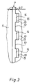
- a cylinder 1 of a rotary printing machine for receiving flexible plates 2 with bent ends 3, 4 with at least one narrow slot 7 extending parallel to its axis of rotation and extending from a lateral surface 6 of the cylinder 1 into its interior 5.
- Legs 8, 9 are folded at the ends 3, 4.
- the leg 9 of the end 4 which runs after the end has in the present example a number of rectangular cutouts 11 arranged next to one another in the axial direction.
- the slot 7 is preferably rectangular in cross section.
- a side surface 13 of the slot 7 facing the end 4 of the plate 2 is provided with a number of U-shaped recesses 14 running parallel to this side surface 13.
- Recesses 14 each have a spring-back space 16 pointing outwards in the direction of the lateral surface 6 of the cylinder 1, so that the respective depression 14 widens in the circumferential direction of the cylinder 1 and forms a bending edge 15 at its transition.
- a bore 17 running parallel to the slot 7 is made in the cylinder 1.
- a pivot lever 18, which in the present embodiment as a spindle 18 with a radius r18, z. B. r18 15 mm, is pivotally mounted centrally.
- the grooves 22 of the spindle 18 and the recess 14 of the slot 7 of the cylinder 1 are adapted to one another.
- an axially extending slot 23 which extends radially from the lateral surface 19 into an interior of the spindle 18, is introduced.
- ends 24 of flexible, but pressure and tension-resistant tongues 26 are suspended, which in the present example as leaf springs, for.
- tongues 26 lie in the U-shaped grooves 22 of the spindle 18 and fit in installed state of the shape of the spindle 18.
- a second, not connected to the spindle 18 end of the tongue 26 is formed in the direction of the leading end 3 of the plate 2 and acting in the direction of the spindle 18 barb 27.
- An outside of the barb 27 pointing in the direction of the lateral surface 6 of the cylinder 1 is provided with a bevel 28 pointing in the direction of the leading end 3 of the plate 2.
- a cam 29 pointing in the direction of the leading end 3 of the plate 2.
- the tongues 26 extend over a length l26, z. B.
- the axial position of the recesses 14 of the slot 7, the grooves 22 of the spindle 18 and the tongues 26 are adapted to one another.
- the operation of the device according to the invention is as follows: In an insertion position (FIG. 1) of the spindle 18, the barb 27 of the respective tongue 26 is located in the area of the resilience space 16 of the recesses 14, just below the lateral surface 6 of the cylinder 1. In this position, the leading, beveled end 3 of the plate is first 2 led into the slot 7. Then the leg 9 of the trailing end 4 of the plate 2, which is provided with cutouts 11 in the area of the tongues 26, is brought into the slot 7. Here, the leg 9 abuts the bevel 28 of the barbs 27 and presses them around the bending edge 15 in the Spring back space 16 of the recess 14 of the slot 7.
- the spindle 18 is rotated counterclockwise, whereby the tongues 26 pull the suspended leg 9 of the plate 2 into the slot 7. Barbs 27 and legs 9 remain in the slot 7. After the clamping process has been completed, the spindle 18 is locked in a rotationally fixed or spring-loaded manner.
- the spindle 16 is rotated clockwise, the cams 29 of the tongues 26 pressing against the leg 9 of the end 4 after the end.
- the tongues 27 spring outward into their extended position, so that the tongues 27 are tangential with respect to the spindle 16 and extend in the depressions 14 in the slot 7.
- the spindle 18 is rotated until the leg 9 of the trailing end 4 is completely removed from the slot 7, i.e. the cams 29 of the tongues 26 are in the area of the lateral surface 6 of the cylinder 1.
- the trailing end 4 of the plate 2 can be removed from the tongue 27.
- the device according to the invention can act on both ends 3, 4 of the plate 2 simultaneously or a separate device can be provided for each end 3, 4.
- the slot 7 can also be widened to the extent that both the folded ends 3, 4 and the tongues 21 are received and the spring-back space 16 is also formed.
- the slot 7 can be widened by the depth of the U-shaped depressions 14 described in the first example, and these depressions 14 can then be omitted.
- the side surface 13 of the slot 7 would be provided with an axially extending, bead-like or hemispherical elevation forming the bending edge 15. A spring-back space 16 is thus also created between such an increase and the beginning 10 of the slot 7.
Landscapes
- Supply, Installation And Extraction Of Printed Sheets Or Plates (AREA)
Applications Claiming Priority (2)
| Application Number | Priority Date | Filing Date | Title |
|---|---|---|---|
| DE19509563 | 1995-03-16 | ||
| DE19509563A DE19509563C2 (de) | 1995-03-16 | 1995-03-16 | Zylinder mit einer Vorrichtung zum Spannen von Platten |
Publications (2)
| Publication Number | Publication Date |
|---|---|
| EP0732202A1 true EP0732202A1 (fr) | 1996-09-18 |
| EP0732202B1 EP0732202B1 (fr) | 1998-06-03 |
Family
ID=7756856
Family Applications (1)
| Application Number | Title | Priority Date | Filing Date |
|---|---|---|---|
| EP96103836A Expired - Lifetime EP0732202B1 (fr) | 1995-03-16 | 1996-03-12 | Cylindre avec un dispositif pour tendre une plaque d'impression |
Country Status (4)
| Country | Link |
|---|---|
| US (1) | US5644984A (fr) |
| EP (1) | EP0732202B1 (fr) |
| JP (1) | JP2801578B2 (fr) |
| DE (2) | DE19509563C2 (fr) |
Families Citing this family (9)
| Publication number | Priority date | Publication date | Assignee | Title |
|---|---|---|---|---|
| FR2733718B1 (fr) * | 1995-05-04 | 1997-08-01 | Heidelberg Harris Sa | Dispositif de liaison entre des elements de retenue et une traverse d'un cylindre de forme d'impression |
| US6131513A (en) * | 1998-10-23 | 2000-10-17 | Heidelberger Druckmaschinen Ag | Printing press with simple lock-up plate cylinder |
| ATE255502T1 (de) * | 1999-03-26 | 2003-12-15 | Heidelberger Druckmasch Ag | Einrichtung zum spannen von druckplatten in spannkanälen reduzierter grösse |
| US6378430B1 (en) | 1999-10-15 | 2002-04-30 | King Press Corporation | Cylinder with plate gripping device |
| JP3446122B2 (ja) * | 2000-07-12 | 2003-09-16 | 株式会社東京機械製作所 | ブランケット胴 |
| DE10208262A1 (de) | 2002-02-26 | 2003-09-04 | Roland Man Druckmasch | Vorrichtung zum Befestigen einer Bespannung auf einem Druckwerkzylinder |
| FR2844743B1 (fr) * | 2002-09-19 | 2004-12-17 | Goss Systemes Graphiques Nante | Ensemble comprenant une unite de blanchet et un cylindre a dispositif de fixation de blanchet, cylindre, unite de blanchet et presse offset correspondants |
| DE102010001751B4 (de) | 2010-02-10 | 2013-05-16 | Koenig & Bauer Aktiengesellschaft | Vorrichtung zum Befestigen zumindest eines Aufzugs auf einem Zylinder |
| US10737481B2 (en) * | 2017-07-03 | 2020-08-11 | Manroland Goss Web Systems Gmbh | Plate cylinder with plate lockup mechanism and related printing press and method |
Citations (2)
| Publication number | Priority date | Publication date | Assignee | Title |
|---|---|---|---|---|
| US2109152A (en) * | 1937-03-26 | 1938-02-22 | Meisel Press Mfg Company | Securing plate on printing press cylinders |
| JPH02103148A (ja) * | 1988-10-13 | 1990-04-16 | Mitsubishi Heavy Ind Ltd | 版締め装置 |
Family Cites Families (6)
| Publication number | Priority date | Publication date | Assignee | Title |
|---|---|---|---|---|
| US3626848A (en) * | 1969-06-09 | 1971-12-14 | American Rockwell Corp | Lockup for thin plates |
| DE2126941A1 (de) * | 1971-05-29 | 1972-11-30 | Albert Schnellpressen | Vorrichtung zum Spannen von biegsamen Druckplatten auf dem Formzylinder von Rotationsdruckmaschinen |
| US3727551A (en) * | 1971-07-22 | 1973-04-17 | North American Rockwell | Reversible lockup for flexible printing plate |
| DE2225016C3 (de) * | 1972-05-23 | 1976-01-29 | Koenig & Bauer Ag | Vorrichtung zum aufspannen von biegsamen druckplatten auf formzylinder von rotationsdruckmaschinen |
| DE4238343C2 (de) * | 1992-11-13 | 2003-03-27 | Kocher & Beck Gmbh & Co Rotati | Spannvorrichtung für ein Klischee |
| FR2709090B1 (fr) * | 1993-08-20 | 1995-11-10 | Heidelberg Harris Sa | Dispositif à crochet et escamotable pour maintenir une plaque d'impression sur un cylindre porte-plaque, dans une imprimante rotative, et imprimante rotative comportant un tel dispositif. |
-
1995
- 1995-03-16 DE DE19509563A patent/DE19509563C2/de not_active Expired - Fee Related
-
1996
- 1996-03-12 EP EP96103836A patent/EP0732202B1/fr not_active Expired - Lifetime
- 1996-03-12 DE DE59600234T patent/DE59600234D1/de not_active Expired - Fee Related
- 1996-03-13 JP JP8056348A patent/JP2801578B2/ja not_active Expired - Lifetime
- 1996-03-15 US US08/616,578 patent/US5644984A/en not_active Expired - Fee Related
Patent Citations (2)
| Publication number | Priority date | Publication date | Assignee | Title |
|---|---|---|---|---|
| US2109152A (en) * | 1937-03-26 | 1938-02-22 | Meisel Press Mfg Company | Securing plate on printing press cylinders |
| JPH02103148A (ja) * | 1988-10-13 | 1990-04-16 | Mitsubishi Heavy Ind Ltd | 版締め装置 |
Non-Patent Citations (1)
| Title |
|---|
| PATENT ABSTRACTS OF JAPAN vol. 14, no. 311 (M - 0994) 4 July 1990 (1990-07-04) * |
Also Published As
| Publication number | Publication date |
|---|---|
| DE59600234D1 (de) | 1998-07-09 |
| EP0732202B1 (fr) | 1998-06-03 |
| DE19509563A1 (de) | 1996-09-19 |
| JPH08267718A (ja) | 1996-10-15 |
| JP2801578B2 (ja) | 1998-09-21 |
| DE19509563C2 (de) | 1997-01-23 |
| US5644984A (en) | 1997-07-08 |
Similar Documents
| Publication | Publication Date | Title |
|---|---|---|
| EP1278636B1 (fr) | Dispositif pour fixer une plaque souple | |
| EP0732202B1 (fr) | Cylindre avec un dispositif pour tendre une plaque d'impression | |
| DE19509561C2 (de) | Vorrichtung zum Klemmen von Platten auf einem Zylinder | |
| WO2000073074A2 (fr) | Dispositif pour fixer une plaque souple | |
| EP0748688B1 (fr) | Dispositif pour un système de retenu sous forme de fente | |
| EP1350624B1 (fr) | Dispositif pour la fixation d'une plaque flexible | |
| EP1481803A1 (fr) | Cylindre porte-plaque pour une machine d'impression | |
| DE4444062A1 (de) | Verstellbare Ausrichtvorrichtung für Druckplatten | |
| DE19541249B4 (de) | Gummizylinder mit einer Gummitucheinheit und mit einer Vorrichtung zum Befestigen der Gummitucheinheit | |
| CH691452A5 (de) | Vorrichtung zum Befestigen einer Gummitucheinheit auf einem Gummizylinder. | |
| EP0732203B1 (fr) | Dispositif tendeur | |
| EP0755785B1 (fr) | Dispositif de fixation d'une plaque avec réduction de la zône sans pression | |
| EP0930972A1 (fr) | Dispositif pour enlever des plaques | |
| EP0592856B1 (fr) | Dispositif de serrage pour fixer une forme d'impression flexible à la surface d'un cylindre | |
| EP1268210A2 (fr) | Dispositif pour serrer et/ou bloquer des plaques souples | |
| DE19509562C1 (de) | Vorrichtung zum Lösen von Platten von einem Zylinder | |
| EP1543967A2 (fr) | Procédé pour tendre un habillage sur un cylindre et procédé pour détendre l'habillage d'un cylindre d'une machine à imprimer | |
| DE19533178C2 (de) | Zylinder | |
| EP0995597B1 (fr) | Cylindre de plaque dans une machine d'impression avec dispositif de tension de plaque | |
| CH658337A5 (en) | Locking mechanism | |
| DE2559387A1 (de) | Sattel zur aufnahme einer flexiblen druckplatte | |
| EP0992356B1 (fr) | Dispositif d'impression | |
| DE19841912A1 (de) | Vorrichtung zum Befestigen von biegsamen Druckformen | |
| DE102004062598A1 (de) | Vorrichtung für einen Druckzylinder, insbesondere Offsetdruckzylinder für Rollen-Rotationsdruckmaschinen |
Legal Events
| Date | Code | Title | Description |
|---|---|---|---|
| PUAI | Public reference made under article 153(3) epc to a published international application that has entered the european phase |
Free format text: ORIGINAL CODE: 0009012 |
|
| AK | Designated contracting states |
Kind code of ref document: A1 Designated state(s): CH DE FR GB IT LI SE |
|
| 17P | Request for examination filed |
Effective date: 19970313 |
|
| GRAG | Despatch of communication of intention to grant |
Free format text: ORIGINAL CODE: EPIDOS AGRA |
|
| GRAG | Despatch of communication of intention to grant |
Free format text: ORIGINAL CODE: EPIDOS AGRA |
|
| GRAH | Despatch of communication of intention to grant a patent |
Free format text: ORIGINAL CODE: EPIDOS IGRA |
|
| 17Q | First examination report despatched |
Effective date: 19970919 |
|
| ITF | It: translation for a ep patent filed |
Owner name: DE DOMINICIS & MAYER S.R.L. |
|
| GRAH | Despatch of communication of intention to grant a patent |
Free format text: ORIGINAL CODE: EPIDOS IGRA |
|
| GRAA | (expected) grant |
Free format text: ORIGINAL CODE: 0009210 |
|
| AK | Designated contracting states |
Kind code of ref document: B1 Designated state(s): CH DE FR GB IT LI SE |
|
| ET | Fr: translation filed | ||
| REG | Reference to a national code |
Ref country code: CH Ref legal event code: EP |
|
| GBT | Gb: translation of ep patent filed (gb section 77(6)(a)/1977) |
Effective date: 19980603 |
|
| REF | Corresponds to: |
Ref document number: 59600234 Country of ref document: DE Date of ref document: 19980709 |
|
| RAP2 | Party data changed (patent owner data changed or rights of a patent transferred) |
Owner name: KOENIG & BAUER AKTIENGESELLSCHAFT |
|
| PLBE | No opposition filed within time limit |
Free format text: ORIGINAL CODE: 0009261 |
|
| STAA | Information on the status of an ep patent application or granted ep patent |
Free format text: STATUS: NO OPPOSITION FILED WITHIN TIME LIMIT |
|
| 26N | No opposition filed | ||
| REG | Reference to a national code |
Ref country code: GB Ref legal event code: IF02 |
|
| PGFP | Annual fee paid to national office [announced via postgrant information from national office to epo] |
Ref country code: GB Payment date: 20020227 Year of fee payment: 7 |
|
| PGFP | Annual fee paid to national office [announced via postgrant information from national office to epo] |
Ref country code: FR Payment date: 20020322 Year of fee payment: 7 |
|
| PGFP | Annual fee paid to national office [announced via postgrant information from national office to epo] |
Ref country code: SE Payment date: 20020402 Year of fee payment: 7 |
|
| PGFP | Annual fee paid to national office [announced via postgrant information from national office to epo] |
Ref country code: CH Payment date: 20020405 Year of fee payment: 7 |
|
| PG25 | Lapsed in a contracting state [announced via postgrant information from national office to epo] |
Ref country code: GB Free format text: LAPSE BECAUSE OF NON-PAYMENT OF DUE FEES Effective date: 20030312 |
|
| PG25 | Lapsed in a contracting state [announced via postgrant information from national office to epo] |
Ref country code: SE Free format text: LAPSE BECAUSE OF NON-PAYMENT OF DUE FEES Effective date: 20030313 |
|
| PG25 | Lapsed in a contracting state [announced via postgrant information from national office to epo] |
Ref country code: LI Free format text: LAPSE BECAUSE OF NON-PAYMENT OF DUE FEES Effective date: 20030331 Ref country code: CH Free format text: LAPSE BECAUSE OF NON-PAYMENT OF DUE FEES Effective date: 20030331 |
|
| EUG | Se: european patent has lapsed | ||
| GBPC | Gb: european patent ceased through non-payment of renewal fee |
Effective date: 20030312 |
|
| REG | Reference to a national code |
Ref country code: CH Ref legal event code: PL |
|
| PG25 | Lapsed in a contracting state [announced via postgrant information from national office to epo] |
Ref country code: FR Free format text: LAPSE BECAUSE OF NON-PAYMENT OF DUE FEES Effective date: 20031127 |
|
| REG | Reference to a national code |
Ref country code: FR Ref legal event code: ST |
|
| PG25 | Lapsed in a contracting state [announced via postgrant information from national office to epo] |
Ref country code: IT Free format text: LAPSE BECAUSE OF NON-PAYMENT OF DUE FEES;WARNING: LAPSES OF ITALIAN PATENTS WITH EFFECTIVE DATE BEFORE 2007 MAY HAVE OCCURRED AT ANY TIME BEFORE 2007. THE CORRECT EFFECTIVE DATE MAY BE DIFFERENT FROM THE ONE RECORDED. Effective date: 20050312 |
|
| PGFP | Annual fee paid to national office [announced via postgrant information from national office to epo] |
Ref country code: DE Payment date: 20060316 Year of fee payment: 11 |
|
| PG25 | Lapsed in a contracting state [announced via postgrant information from national office to epo] |
Ref country code: DE Free format text: LAPSE BECAUSE OF NON-PAYMENT OF DUE FEES Effective date: 20071002 |