EP0731397A1 - Method and system for optimizing plant utility - Google Patents
Method and system for optimizing plant utility Download PDFInfo
- Publication number
- EP0731397A1 EP0731397A1 EP95932239A EP95932239A EP0731397A1 EP 0731397 A1 EP0731397 A1 EP 0731397A1 EP 95932239 A EP95932239 A EP 95932239A EP 95932239 A EP95932239 A EP 95932239A EP 0731397 A1 EP0731397 A1 EP 0731397A1
- Authority
- EP
- European Patent Office
- Prior art keywords
- steam
- plant
- total
- physical amounts
- turbines
- Prior art date
- Legal status (The legal status is an assumption and is not a legal conclusion. Google has not performed a legal analysis and makes no representation as to the accuracy of the status listed.)
- Granted
Links
Images


Classifications
-
- F—MECHANICAL ENGINEERING; LIGHTING; HEATING; WEAPONS; BLASTING
- F01—MACHINES OR ENGINES IN GENERAL; ENGINE PLANTS IN GENERAL; STEAM ENGINES
- F01K—STEAM ENGINE PLANTS; STEAM ACCUMULATORS; ENGINE PLANTS NOT OTHERWISE PROVIDED FOR; ENGINES USING SPECIAL WORKING FLUIDS OR CYCLES
- F01K13/00—General layout or general methods of operation of complete plants
- F01K13/02—Controlling, e.g. stopping or starting
-
- G—PHYSICS
- G05—CONTROLLING; REGULATING
- G05B—CONTROL OR REGULATING SYSTEMS IN GENERAL; FUNCTIONAL ELEMENTS OF SUCH SYSTEMS; MONITORING OR TESTING ARRANGEMENTS FOR SUCH SYSTEMS OR ELEMENTS
- G05B13/00—Adaptive control systems, i.e. systems automatically adjusting themselves to have a performance which is optimum according to some preassigned criterion
- G05B13/02—Adaptive control systems, i.e. systems automatically adjusting themselves to have a performance which is optimum according to some preassigned criterion electric
- G05B13/04—Adaptive control systems, i.e. systems automatically adjusting themselves to have a performance which is optimum according to some preassigned criterion electric involving the use of models or simulators
- G05B13/042—Adaptive control systems, i.e. systems automatically adjusting themselves to have a performance which is optimum according to some preassigned criterion electric involving the use of models or simulators in which a parameter or coefficient is automatically adjusted to optimise the performance
Abstract
Description
- The present invention relates to a plant utility optimizing method for optimizing an operation state of a plant system while satisfying various demands for the plant system and to an optimizing system.
- In a factory having, for example, normally used steam turbine generators, an optimal operation system for a power generation plant operates the power generation plant (hereinafter referred to as a BTG plant) so as to supply energy which is required in a manufacturing process to power and steam loads at a minimal cost.
- FIG. 18 shows a conceptual diagram of the BTG plant and FIG. 19 shows a practical system arrangement of the BTG plant.
- As shown in FIG. 18, a plurality (Xm) of steam turbines T (hereinafter referred to simply as the turbines) are operated by the steam generated by steam generation boilers B (hereinafter referred to as the boilers) using fuel F such as the oil, gas, coal, recovered black liquor, etc. The respective turbine T drives a corresponding generator G to generate electric power. The electric power is supplied to electric power loads in the associated plant. The steam bled from the turbine T is supplied to the steam loads in the plant. In this case, if only an electric power generated from the generators is not sufficient to meet the electric load demand in the plant, a commercial power is supplied to the loads.
- The system arrangement of the BTG plant comprises, as shown in FIG. 19 for instance, boilers B1, B2 using the well-controlled fuel such as the oil, gas, etc., boilers B3, B4 using the fuel of better economic efficiency such as the coal, black liquor, etc., a high-pressure steam header SL supplied with the steam generated from the boilers B1, B2, a high-pressure steam header SH supplied with the steam generated from the boilers B3, B4, steam turbines T1, T2 operated by the steam pressure coming from the high-pressure vapor header SH and driving the generator G, steam turbines T3, T4 operated by the steam pressure coming from the high-pressure steam header SL and driving the generator G, a supply header DH for supplying the steam which is bled from the steam turbines T1, T2 to the associated loads, and a supply header DL for supplying the steam which is bled from the steam turbines T3, T4 to the associated loads. Here, the pressure of the high-pressure steam header SH is higher than that of the high-pressure steam header SL, while the pressure of the steam supply header DH is higher than that of the steam supply header DL.
- The high-pressure steam and low-pressure steam supplied to the headers DH and DL are supplied, respectively, to the steam loads H and L in the plant.
- A pressure-reducing valve RPV1 is connected between the high-pressure steam header SH and the high-pressure steam header SL and a pressure-reducing valve is connected between the headers DH and DL.
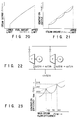
- In the BTG plant, the fuel amount/steam generation amount characteristic of the boiler shows a gentle, near-flat curve as shown in FIG. 20. According to the boiler characteristic as shown in FIG. 20, the evaporation amount from the boiler is found to be substantially in proportion to the fuel amount in an upper/lower limit operation range.
- On the other hand, the steam amount/generation power output characteristic of the turbine has a non-convex characteristic called a valve loop characteristic (valve point characteristic), the characteristic curve having several recesses. The non-convex characteristic is due to a fall in a shaft output resulting from a pressure drop produced when the steam input valve is half-opened. In the characteristic curve proposed by the apparatus manufacturer as the characteristic curve of the turbine, a plurality of peak points are normally connected together to provide an envelope, an aspect which is different from a real aspect shown in FIG. 21. That is, according to the turbine characteristic as shown in FIG. 21 it has been found that the generation output power differs in the upper/lower limit range in terms of the valve points and their intervening recesses.
- Incidentally, at the optimized operation of the BTG plant the steam distribution of the boiler and turbine and that of the commercial power are varied so that the operation is performed at a minimal cost. This effect will be explained with reference to FIGS. 22 and 23.
- Let it be assumed that, as shown in FIG. 22, two turbines of the same characteristic are operated and, at this time, the steam load is at 100 T/H.
- Here, the load steam, being equally distributed to the two turbines, becomes a 50 T/H each and, at this time, the generated power amount becomes

- If, on the other hand, the load steam is distributed to the two turbines, one at 40 T/H and the other at 60 T/H, the generated power output becomes 210 × 40 + 218 × 60 = 21480 KW. From this it has been found that 7.4 % more output can be generated by varying the distribution of the steam to the turbines.
- In the optimizing operation system of the BTG plant, therefore, the BTG plant is modeled with a mathematical formula and a cost minimum is found from boiler/turbine distribution combinations which can satisfy the electric power/steam loads.
- Given that a target total energy cost is expressed with a function, the BTG plant model with a mathematically formatted distribution amount at which the function becomes minimal (or maximal) is found, as a mathematical solution, with a high-speed computer. By operating the BTG plant to reach this distribution amount it is possible to operate, at a minimal cost at all times, the BTG plant which would be complex and impossible to the human.
- FIG. 26 is a block diagram showing one form of an optimal operation system of this kind. In FIG. 26, the optimal operation system of the BTG plant comprises a
plant model 32 and a total energy cost minimizingpoint calculating section 31. - The characteristics and operation restrictions of the turbines, boilers, pressure-reducing valves, etc., as the constituent elements of the BTG plant, as well as the electric power balance and steam balance at each system part, are provided from the
plant model 32 to the total energy cost minimizingpoint calculating section 31. - By giving the actual load amount (electric power and steam) as the plant state of the
plant model 32 to the total energy cost minimizingpoint calculating section 31 an optimal distribution is found with the use of a linear programming (LP) or a nonlinear programming (NLP). - The linear or nonlinear programming conventionally used thus far has advantages and disadvantages.
- That is, the mathematically formulated model as a target in the linear programming can solve only all linear (linear equation) problem and it is necessary, therefore, to apply the plant model, being nonlinear in actual practice, through a linear approximation. For this reason, it is not possible to avoid a lowering in the accuracy of a solution through such approximation, so that the cost lowering effect is small.
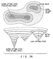
- The non-linear programming can solve the multi-dimensional program and, therefore, handle the nonlinear plant model but, in the case where the problem to be handled is non-linear, it is possible to obtain only a local optimization solution with the attendant drawback.
- In the case where, for example, a valve point characteristic of the turbine is non-convex and multi-peaked, it is possible to, for a local optimization point and global optimization point as shown as the conceptual diagram, obtain only an optimal point (local optimization solution) in the vicinity of a calculated initial value so that no true optimal point (global optimal solution) can be obtained. It is because the object function is multi-peaked.
- Further, in order to obtain a solution as near to a true optimal point as possible with the use of the nonlinear programming, the initial value and search method have to be modified in accordance with the problem. However, the search logic becomes complex when aiming at an optimal solution and lots of time and labor are taken in tuning calculation parameters.
- For the search of the optimal point with the use of the nonlinear programming (NLP) it is necessary to usually determine the initial value and search range.
- The initial value is used to determine from where the calculation is started. The method of how to determine the initial value is often by, for example,
- i) using the current operation state,
- ii) getting the respective characteristic functions all linearly approximate and utilizing a solution obtained by the linear programming (LP).
- Further, for the Lagrande multiplier method-plus-conjugate gradient method often used as the NLP alogrithm, the search range has to be tuned to the problem so that a single peak (trough) is obtained in the search range.
- FIG. 25 shows a relation among the linear, non-linear and true optimal resolutions.
- In FIG. 25, the optimal solution by the LP is located at a
 D
D point.
 - Further, when the initial value is started from aKpoint by the NLP, it is possible to obtain, as an optimal solution, a minimal pointAin the vicinity of the search done. This, being greater than a true optimal pointT, provides a local optimal point.
- A pointBis one shifted by L2 from the local optimal pointAat the search of a better point. In the case where theBpoint is located in a position lower than theApoint, the optimal point is shifted to theBpoint. And a local optimal pointTin the vicinity of the search is obtained as an optimal solution as in the case of theApoint.
- However, a pointCspaced apart by L1 is located in a position higher than theApoint, so that there is no shift of the optimal point.
- In the search of the optimal point with the use of the NLP method there is no right determination of the search range L and hence no guarantee to reach a true optimal pointT.
- Since the non-linear programming is based on the assumption that the problem to be dealt with is on the convex characteristic, it cannot be used unless it is known whether there is one peak (single peak) and wether the position of the peak is located.
- It is found that no local optimal point is searched on a multi-peak problem containing a plurality of non-convex characteristics as in the case of the valve characteristics of the turbine.
- In the conventional optimal system, therefore, the operation is done at the local optimal point and it may be said that there is room for efficiency improvement up to the local optimal point.
- For the nonlinear programming method it has been difficult to tune calculation parameters such as the initial value and a way of how to determine the search range and it has been very difficult, for the user with no expert's knowledge on the optimization computation, to do the system changes of the target energy plant and to do the system maintenance such as the correction of a plant model corresponding to apparatus changes.
- In the finding of an optimal distribution at the total energy cost optimization point calculating section it has been possible for the conventional plant utility optimization system to obtain a linear solution of poor accuracy only or a nonlinear solution allowing a local optimization solution only and it has been difficult to, for the nonlinear solution, tune the calculation parameters such as the initial value and search range.
- A first object of the present invention is to provide a plant utility optimization method which can satisfy various demands for a plant system and find an optimal operation state reflecting non-convex characteristics possessed by plant elements.
- A second object of the present invention is to provide a plant optimization system which can ensure the obtainment of a solution of higher accuracy than in a conventional system and can obviate the need to tune calculation parameters involved and, in addition, enables the user with no expert's knowledge on optimization calculation to do the system changes of a target energy plant and do a system maintenance such as the correction of a plant model corresponding to apparatus changes.
- A utility optimizing method of the present invention is provided for searching optimal operation parameters of a plant including a plurality of first plant elements having a linear input/output characteristic with first physical amounts as an input and second physical amounts as an output and a plurality of second plant elements having an input/output characteristic with the second physical amounts as an input, corresponding to the output of the first plant element, and third physical amounts as an output, the input/output characteristic containing a non-convex characteristic portion, the method comprising:
- a first processing step of finding a distribution of the second physical amounts to the second plant elements by a dynamic programming to maximize the sum total of the third physical amounts corresponding to the sum total of the second physical amounts in a predetermined range satisfying a first demand of the second physical amounts in a first group and output from the second plant elements associated with the first group;
- a second processing step of finding a distribution of the second physical amounts to the second plant elements by the dynamic programming on the basis of a set of the sum total of the second physical amounts, sum total of the third physical amounts and distribution of the second physical amounts to the second plant elements obtained by the first processing step to maximize the sum total of the third physical amounts corresponding to the sum total of the second physical amounts to the second plant elements and output from the respective second plant elements; and
- a third processing step of finding by a linear programming or nonlinear programming, the first physical amounts input to the second plant elements and evaluation values, necessary for supplying the first physical amounts, with respect to each set of the sum total of the second physical amounts, sum total of the third physical amounts and distribution of the second physical amounts to the second plant elements obtained at the second processing step.
- Further, a utility optimizing method of the present invention is provided for searching optimal operation parameters of a plant including a plurality of first plant elements having a linear input/output characteristic with first physical amounts as an input and second physical amounts as an output and a plurality of second plant elements having a linear input/output characteristic with the second physical amounts as an input, corresponding to the output of the first plant elements, and third physical amounts as an output, the input/output characteristic containing a non-convex characteristic portion, the method comprising:
- a first processing step of finding a distribution of the second physical amounts to the second plant elements by a dynamic programming to maximize the sum total of the third physical amounts corresponding to the sum total of the second physical amounts in a predetermined range satisfying a first demand for a group of such second physical amounts and output from the second plant elements associated with the group;
- a second processing step of finding a distribution of the second physical amounts to the second plant elements by a dynamic programming on the basis of a set of the sum total of the second physical amounts, sum total of the third physical amounts and distribution of the second physical amounts to the second plant elements obtained by the first processing step at each second physical amount in a group to maximize the sum total of the third physical amounts corresponding to the sum total of the second physical amounts to all the second plant elements and output from said the second plant elements;
- a third processing step of finding, by a linear or a nonlinear programming, the first physical amounts input to the second plant elements and first evaluation values, necessary to supply the first physical amounts, with respect to the respective set of the sum total of the second physical amounts, sum total of the third physical amounts and distribution of the second physical amounts to the second plant elements obtained by the second processing step;
- a fourth processing step of, on the basis of a respective set of the sum total of the third physical amounts and first evaluation values, necessary for the first physical amounts, calculating second evaluation values required to receive a power which corresponds to a shortage in a predetermined second demand for the sum total of the third physical amounts to find a total evaluation value for each set and deciding, as an optimal solution, each value belonging to a set in which the total evaluation value is minimized.
- Further, a utility optimizing method of the present invention is provided for searching optimal operation parameters of a power generation plant including a plurality of boilers, a plurality of turbines operated by steams generated from the boilers, and generators driven by the respective turbines to generate electric power in which the electric power is supplied to electric power loads while the steams bled from the respective turbines are supplied to steam loads via a plurality of turbine discharge systems, the method comprising:
- a first processing step of finding a steam flow amount distribution to the respective turbines by a dynamic programming to maximizing the sum total of generation output powers of the turbines corresponding to respective steam flow amounts in a predetermined range satisfying a steam demand to the respective turbine discharge system and connected to the same turbine discharge system;
- a second processing step of, on the basis of a set of the steam flow amount, generation output power and steam flow amount distribution obtained by the first processing step at each turbine discharge system, finding a steam flow amount distribution to the respective turbines by a dynamic programming to maximize a total generation output power of all the turbines corresponding to the total input steam flow amounts to all the turbines; and
- a third processing step of finding a supply fuel distribution to the respective boilers and total fuel cost by a linear or a nonlinear programming with respect to each set of the total input steam flow amount, total generation output power and steam flow amount distribution to the respective turbines.
- Further, a utility optimizing method of the present invention is provided for searching optimal operation parameters of a power generation plant including a plurality of boilers, a plurality of turbines operated by steams generated from the boilers, and generators driven by the respective turbines to generate electric power in which the electric power is supplied to electric power loads while the steams bled from the respective turbines are supplied to steam loads via a plurality of turbine discharge systems, comprising the steps of
- a first processing step of finding a steam flow amount distribution to the respective turbines by a dynamic programming to maximize the sum total of generation output powers of the turbines corresponding to the steam flow amounts in a predetermined range satisfying a steam demand to the respective turbine discharge system and connected to the same turbine discharge system;
- a second processing step of finding a steam flow amount distribution to the respective turbines by the dynamic programming on the basis of a set of the steam flow amount, generation output power and steam flow amount distribution obtained by the first processing step at each turbine discharge system to maximize a total generation output power of the turbines corresponding to a total input steam flow amount to all the turbines;
- a third processing step of finding, by a linear or nonlinear programming, a supply fuel distribution to the respective boilers and total fuel cost with respect to each set of the total input steam flow amount, total generation output power and steam flow amount distribution to the respective turbines; and
- a fourth processing step of, on the basis of each set of a total generation output power and total fuel cost obtained by the third processing step, calculating an external cost required to receive a power which corresponds to a shortage in a predetermined power demand for the total generation output power from an outside source to find a total cost for each set and deciding, as an optimal solution, each value belonging to a set in which the total cost is minimized.
- Further, in a power generation plant including a plurality of boilers, a plurality of turbines operated by steams generated from the boilers and generators driven by the respective turbines to generate electric power wherein the electric power is supplied to electric power loads while the steams bled from the respective turbines are supplied to the steam loads, a plant utility optimizing system of the present invention comprising:
- a plant model prepared by separating into a turbine-side and a boiler-side model;
- a turbine output maximum point calculating section for deciding such a steam distribution of the turbines as to maximizing a total of outputs of the respective turbines for each supply steam amount given from the turbine-side model in the plant model;
- a fuel cost minimizing point calculating section for deciding such a steam distribution amount of each boiler as to generate at a minimal cost, the sum total of per pressure supply steam amounts given from the boiler-side model at each point found by the turbine output maximum point calculating section; and
- a total energy cost minimizing point calculating section for searching a total energy cost minimum operation point to electric loads and steam loads on the basis of a steam distribution amount decided by the fuel cost minimizing point calculating section. Further, in a power generation plant including a plurality of boilers, a plurality of turbines operated by steams generated from the boilers and generators driven by the respective turbines to generate electric power in which the electric power is supplied to electric power loads while steam bled from the respective turbine is supplied to steam loads, a plant utility optimizing system of the present invention comprising:
- a plant model prepared by separating into a turbine-side and a boiler-side model;
- a turbine output maximum point calculating section for deciding such a steam distribution of the turbines as to maximize a total of outputs of the respective turbines for each supply steam amount given from the turbine-side model;
- a fuel cost minimizing point calculating section for deciding such a steam distribution amount of the respective boilers as to generate, at a minimal cost, the sum total of per pressure supply steam amounts given from the boiler-side model at each point found by the turbine output maximum point calculating section;
- a total energy cost minimizing point calculating section for searching a total energy cost minimum operation point to electric power loads and steam loads on the basis of a steam distribution amount of the respective boilers decided by the fuel cost minimizing point calculating section;
- a plant model preparing section for preparing/editing system graphics for modifying or correcting plant models used under the calculation of the turbine output maximum point calculating section and fuel cost minimizing point calculating section and system models described with a mathematical expression; and
- a data generator for generating data necessary for optimal calculation from the model prepared by the plant model preparing section and for giving the data to the turbine-and boiler-side models in the plant model.
- According to the present invention, in the searching of optimal operation parameters in a plant (for example, the turbine-type power generation system) including a plurality of first plant elements having a linear input/output characteristic with first physical amounts (for example, fuel) as an input and second physical amounts (for example, steam amounts) as an output and a plurality of second plant elements having an input/output characteristic with the second physical amounts as an input, corresponding to the output of the first plant elements, and the third physical amounts (for example, output power) as an output, the latter input/output characteristic containing a non-convex characteristic portion, processing is done twice through the utilization of the dynamic programming allowing the non-convex characteristic to be reflected. Once the first demand (for example, steam demand), that is, a demand for the second physical amounts, has been satisfied, sets of the sum total of the second physical amounts, distribution amount of this sum total to all the second plant elements and sum total of the third physical amounts output from all the second plant elements are found, noting that the total amount of various second physical amounts is given here.
- For each set, the first physical amounts input to the respective second elements and first cost required to supply these first physical amounts are found by a linear or a nonlinear programming on the basis of the values in the found set.
- Finally, in the case where, for each set, the sum total of the third physical amounts is smaller than a second demand (for example, an energy demand), a second cost (for example, external cost) required to receive its shortage from an outside is calculated on the basis of the values in the set of the sum total of the third physical amounts and first cost (for example, a total fuel cost) required for the first physical amounts thus obtained to find a total cost for each set and a respective value (for example, the sum total of the second physical amounts, distribution of the second physical amounts to the second plant elements, sum total of the third physical amounts, first physical amounts input to the respective second plant elements, first cost required to supply the first physical amounts, total cost, etc.,) belonging to a set, that is, a set in which that total cost is minimized, is decided as an optimal solution.
- According to the plant utility optimizing system of the present invention, it is possible to decide such a steam distribution (point) of the respective turbines as to maximize a total of the outputs of the respective turbines for each supply steam amount given from the turbine-side model in the plant model and it is also possible to decide such a steam distribution amount of the respective boilers as to generate, at a minimal cost, the sum total of the per pressure supply steam amounts given from the boiler-side model for each point. By searching a total energy cost minimum operation point (including a power buying cost) for the electric loads and above-mentioned loads it is possible to obtain a true optimal point and largely lower a cost involved.
- In addition to the above-mentioned functions, it is also possible to, on the plant model used for calculating the turbine output maximum point and fuel cost minimizing point, prepare/edit the system graphics and system model described with the mathematical expression and generate, from this model, data necessary for optimal calculation. By doing so, it is possible to readily modify or correct the model.
-
- FIG. 1 diagrammatically shows a plant energy system according to a first embodiment of the present invention;
- FIG. 2 is a view showing one example showing a schematic flow relating to a plant utility optimizing system according to the first embodiment of the present invention;
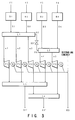
- FIG. 3 is a view showing a major section of the plant system according to the first embodiment;
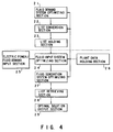
- FIG. 4 is a schematic view showing a major section of the plant utility optimizing system according to the first embodiment;
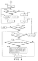
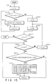
- FIG. 5 is a flow chart showing one example of the operation of a fluid demand system optimizing section;
- FIG. 6 is a flow chart showing the example of the operation of the fluid demand system optimizing section;
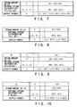
- FIG. 7 is a view showing a relation of an optimal steam distribution and output power to each steam amount of an L3 group;
- FIG. 8 is a view showing a relation of an optimal steam distribution and output power to each steam amount of an L4 group;
- FIG. 9 is a view showing a relation of an optimal steam distribution and output power to each steam amount of an L3 group;
- FIG. 10 is a view showing a relation of an optimal steam distribution and output power to each steam amount of an L4 group;
- FIG. 11 is a view showing a relation of an optimal steam distribution and output power to each steam amount of an L3 group;
- FIG. 12 is a view showing a relation of an optimal steam distribution and output power to an L4 group;
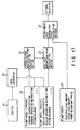
- FIG. 13 is a flow chart showing one example of the operation of a fluid input system optimizing section;
- FIG. 14 is a view showing a relation of an optimal steam distribution and total output power to a total input steam amount;
- FIG. 15 is a view showing a relation of an optimal steam distribution, total output power, fuel distribution and total fuel cost to a total input steam amount;
- FIG. 16 is a view showing respective optimal solution candidates;
- FIG. 17 is a block diagram showing an optimal operation system of a power generation plant according to a second embodiment of the present invention;
- FIG. 18 is a conceptual view showing a BTG plant;
- FIG. 19 is a view showing an example of a system arrangement of a BTG plant;
- FIG. 20 is a characteristic curve showing a relation of the fuel of boilers used in the BTG plant to a steam generation amount;
- FIG. 21 is a characteristic curve showing a relation of a steam generation amount of the turbines used in the BTG plant to a generation power output;
- FIG. 22 is a view showing an example of the operation of two turbines of the same characteristics;
- FIG. 23 is a characteristic showing a relation of a major steam flow amount at the operation of the turbines to a generation output;
- FIG. 24 is a view showing a concept of a local optimal solution and global optical solution to the non-convexity of a valve point characteristic having turbines;
- FIG. 25 is a view showing a relation of a linear solution, non-linear solution and true optimal solution to the non-convexity of a valve point characteristic in turbines; and
- FIG. 26 is a block diagram showing a schematic form of an optimal operation system of a conventional power generation plant.
- A first embodiment of the present invention will be explained below with reference to the accompanying drawings. First, a brief explanation will be given of the present invention.
- As a plant system to which a plant utility optimization system is applied, an explanation will be given below of a non-utility generation system. The non-utility generation system is adapted to reutilize steam discharged from turbines and, there, a demand is made for both a steam discharged from the turbines and an energy output from the generators.
- The plant utility optimizing system of the present embodiment is directed to, while satisfying the steam demand and power demand as well as various kinds of restriction requirements, satisfying an operation state at a minimal total cost through the utilization of a dynamic programming, that is, in such a way as to allow the minimization of the total cost required for the operation of the plant system.
- The above-mentioned dynamic programming is one procedure for solving a decision problem in which an optimal solution is normally decided in a multistage fashion with a result of its analysis providing a precondition to its sequential decision problem. In the dynamic programming, a decision selection sequence for a realizable optimal solution is called a "policy" and the policy of maximizing a specific function (criterion function) of a final state variable is called as an "optimal policy". The dynamic programming utilizes the "principle of optimality" throughout in which the optimal policy has the property that, whatever an initial state and initial decision are, a subsequent decision sequence has to be given the optimal policy with respect to a state produced as a result of the initial decision. The dynamic programming is set out in detail, for example, inDynamic Programming, Princeton University Press, 1957by R. Bellman.
- In a real plant dealt with in the present embodiment it is necessary that an optimal solution be found under the complex restriction conditions because of the reutilization of the steam, the presence of a boiler group, the presence of various steam systems, etc. It has not been possible to derive an optimal solution by the dynamic programming thus far employed.
- With the plant utility optimizing system of the present embodiment, not only means for optimizing the output of the turbine group but also various optimizing means are sequentially combined in an organic way along the arrangement of the plant and, by doing so, it is possible to find an optimal operation state of the plant satisfying a complex demand. Briefly stated, first the processing utilizing the dynamic programming is performed twice and processing utilizing the linear programming is performed once to find a solution (that is, an optimal solution candidate) for optimizing the output of the turbine group corresponding to respective operation state and then decide, as an optimal solution, an operation state for minimizing the total cost.
- Now the plant utility optimizing system of the present embodiment will be explained below in more detail.
- FIG. 1 is a diagrammatic view showing a plant energy system according to the present embodiment. As shown in FIG. 1, the system comprises a plant system including non-utility generation system 11 of a BTG (a boiler/turbine/ generator), an external power input apparatus 12 and
steam system 13, aplant controller 4 for controlling the non-utility generation apparatus 11 and external power input apparatus 12, and a plantutility optimizing system 2 connected to theplant controller 4 to find an optimal operation point (distribution amount) of the respective components in theplant system 6 and transfer the optimal operation distribution amount to theplant controller 4. - In place of being connected to the
plant system 6, the plantutility optimizing system 2 may be of such a type that the inputting and outputting of the data to and from the plantutility optimizing system 2 are done through the use of an information memory medium such as a magnetic disk. - FIG. 2 diagrammatically shows one example of the flow of processing regarding the plant
utility optimizing system 2. - Detailed system configuration information of the
plant system 6 is input to the plant utility optimizing system 2 (step S11). - Step S12 decides a power demand/steam demand and inputs its value to the
plant controller 4. - Step S13 transmits the power demand/steam demand from the
plant controller 4 to the plantutility optimizing system 2 and makes a request to execute optimization processing. - The plant
utility optimizing system 2 searches an optimal solution on the given power/steam demand (step S14). - The plant
utility optimizing system 2 transmits the searched optimal solution to the plant controller 4 (step S15). - Based on the optimal solution given from the plant
utility optimizing system 2 theplant controller 4 controls the plant system (step S16). - FIG. 3 shows a detail of the
plant system 6 in FIG. 1. - The present embodiment is equipped with four steam generation boilers (hereinafter referred to as boilers) B1 to B4, five steam turbines (hereinafter referred to as turbines) T1 to T5 and five generators G.
- The respective boilers B1 to B4 generate steam with the use of fuel fed. Let it be supposed that fuel amounts fed to the respective boilers B1 to B4 are given by f1 to f4 and that steam amounts generated by the boilers B1 to B4 are given by S1 to S4.
- L1 and L2 show high-pressure steam headers of different pressures (L1 is on the high voltage side). Further, S5 and S6 show an input steam amount and output steam amount of a pressure reducing valve 20.
- The respective turbines T1 to T5 have functions p1, p2, p3 and p5, respectively, of an input steam amount-output power characteristic and generate electric powers corresponding to the input steam amounts. The steam amounts input to the respective turbines T1 to T2 are represented by S1 and S5.
- The steams discharged from the respective turbines T1 to T5 are connected to corresponding load steam headers L3, L4 of different pressures. And a steam amount S1' is output from the steam system L3 and a steam amount S2' from the steam system L4.
- The electric powers generated from the generators G driven by the corresponding turbines T1 to T5 are output as a total power.
- The fuel amounts f1 to f4 input to the corresponding boilers B1 to B4 have their upper and lower limit values determined, respectively. Incidentally, further restriction is sometimes added as upper and lower limit values of those amounts of fuel input based on the amounts of fuels currently burned at the respective boilers B1 to B4.
- Regarding the steam amounts S1 to S5 input to the turbines T1 to T5 their upper and lower limit values are determined.
- In such a
plant system 6, steam demands SD1 , SD2 (a minimal value to be satisfied by S1', a minimal value to be satisfied by S2') for the respective steam systems L3, L4, as well as an energy demand ED, are determined. In the case where the energy demand is not satisfied with the total generation power, an external commercial electric power is input for replenishment. - In the case where the total generation amount of all the generators G exceeds the energy demand, a measure is taken to discard any excess portion or sell the generated power.
- Although in the
plant system 6 of the present embodiment the turbines T1 to T5 have been explained as being not of a bleeding type, a plant system regarding the bleeding turbines can be so configured as to incorporate the bleeding turbines into the same arrangement as shown in FIG. 3 where these bleeding turbines are regarded as being connected in parallel with a plurality of turbines of non-bleeding type. - FIG. 4 shows a schematic arrangement of a major portion of the plant
utility optimizing system 2 according to the first embodiment of the present embodiment. As shown in FIG. 4, the plant utility optimizing system of the present embodiment comprises a fluid demandsystem optimizing section 21,list converting section 22,list holding section 23, fluid inputsystem optimizing section 24, energy/fluiddemand input section 25, plantdata holding section 26, fluidgeneration optimizing section 27,list retrieving section 28 and a optimalsolution outputting section 29. - The plant
data holding section 26 stores, therein, the upper and lower limit values of the fuel amounts f1 to f4 input to the respective boilers B1 to B4, upper and lower limit values of steam amounts (steam discharge amounts) input to the respective turbines T1 to T5, functions p1, p2, p3, p4 and p5 of an input steam amount-output power characteristic, and other various constants and functions such as functions of the input/output characteristic of the respective boilers. The plantdata holding section 26 supplies, to the fluid demandsystem optimizing section 21,list conversion section 22, fluid inputsystem optimizing section 24 and fluid generationsystem optimizing section 27, their demanded numerical values and functions as will be set out below. - First, the fluid demand
system optimizing section 21 decides steam discharge amounts S1, S2 and S4 of the respective turbines T1, T2 and T4 through the use of the dynamic programming to maximize the total output power of the generators G driven by the turbines T1, T2 and T4 connected to the steam system L3 and, in this case, the steam flow amounts in the steam system L3 are given their respective values. - FIGS. 5 and 6 show one example of the operation of such fluid demand
system maximizing section 21. In FIGS. 5 and 6, p1, p2, ..., p5 show the characteristic functions of the respective turbines and M1, M2 and M4 show the upper limit values of the discharge steam amounts of the respective turbines T1, T2, T4. For brevity in explanation it is assumed that M1, M2 and M4 are integers and the lower limit values of the steam amounts discharged from the respective turbines T1, T2, T4 all zeroes. Further, T and T' represent arrays, a first [ ] following the T and T' represents a row and the next [ ] represents a column, the following [0] [1] [2] representing first, second and third elements in the row/column. - Here, the steam flow amounts are found for the case where they are given respective integer values from 0 to M1 + M2 + M4.
- A table as shown in FIG. 7 is obtained by the operation as shown in FIGS. 5 and 6.
- Similarly, for the case where the steam flow amounts of steam systems L4 are given respective values, the fluid demand
system optimizing section 21 decides steam discharge amounts S3, S5 of the respective turbines T3, T5 through the use of the dynamic programming to maximize the total output power of the generators G driven by the turbines T3, T5 connected to the steam system L4. - The operation of such fluid demand
system optimizing section 21 is such as to correct M1 and M2 in FIG. 5 to M3 and M5 and correctto Ato "an end" in the case of NO in step S27. - Even in this, the steam flow amount is found in the case where it is given a respective value from 0 to M3 + M5.
- For the respective steam flow amounts of the steam system L4, through the operation of the fluid demand
system optimizing section 21, a table as shown in FIG. 8 is obtained where the optimal steam distribution and output power of the turbines T3, T5 are obtained. - The tables shown in FIGS. 7 and 8 are sent to the next
list conversion section 22. - Here, given that the steam amounts supplied from the boilers B1 to B4 to the L1 and L2 systems are σ1, σ2, then

- Thus, the following relations are established.


- Here,

- The
list conversion section 22 prepares a table as shown in FIG. 9 with the value u added to each column of the table shown in FIG. 7 and a table as shown in FIG. 10 with the valve v to the table as shown in FIG. 8. The value uM in FIG. 9 shows a maximal step value not exceeding

list conversion section 22 sends these Tables as shown in FIGS. 9 and 10 to thelist holding section 23. - Incidentally, simply preparing the tables as shown in FIGS. 9 and 10 by adding the values u and v calculated from the respective steam amounts in the steam system L3 and respective steam amounts in the steam system L4 to the tables as shown in FIGS. 7 and 8 results not necessarily in the values u and v being arranged at regular intervals.
- It is preferable that, in order to make the values u and v a constant step width, the
list conversion section 22 decide the step widths of the values u and v and properly interpolate the steam amount, optimal steam distribution and output voltage with respect to the value u and v on the basis of the values of FIGS. 7 and 8. As the interpolation method the following may be conceived for instance. If the total steam amount corresponding to the values u and v exists on the row of the steam amount of L3, L4 on the tables shown in FIGS. 7 and 8, a corresponding column is adopted as it is and, if such is not the case, a row of a minimal value of those equal to, or exceeding, the total steam amount is adopted. - This is another linear interpolation method by which, if the total steam value corresponding to the values and v exists on the table of FIGS. 7 and 8, a corresponding column is adopted and, if such is not the case, use is made of a column of a minimal value of those exceeding the total steam amount and column of a maximal value of those less than the total steam amount.
- The
list holding section 23 stores, therein, the tables shown in FIGS. 9 and 10 on a given form. - At the time when the plant system is decided, processing up to this can be performed.
- The energy demand and steam demand made from the
plant controller 4 is sent from the energy/liquiddemand input section 25 to the liquid inputsystem optimizing section 24. Upon receipt of the already prepared tables as shown in FIGS. 9 and 10, as set out above, from thelist holding section 23, the fluid inputsystem optimizing section 24 extracts, from the table as shown in FIG. 9, the row in which the steam amount of the steam system L3 satisfies the steam demand SD1 for the L3 system and, similarly, from the table as shown in FIG. 10, the column in which the steam demand SD2 satisfies the steam demand SD2 for the L4 system. - By this operation it is possible to obtain the table as shown in FIGS. 11 and 12. It is to be noted that, in the table as shown in FIG. 11, L3l and L3u are lower and upper limit values of the L3 steam amount as shown in FIG. 9 they satisfy the steam demand for the L3 system and Um, (sm1, sm2, sm4) and Em3 correspond to u, (sM1, sM2, sM4) and output power in the column of L3l. The same thing is also true of uM (sM2, sM2, sM3). The meaning of the respective symbols in Table as shown in FIG. 12 is the same as shown in Table in FIG. 11.
- For the case of letting the total input steam amount be respective values in terms of a high pressure level, the fluid input
system optimizing section 24 uses the dynamic programming based on the tables as shown in FIGS. 11 and 12 to decide steam supply amounts S1 to S5 to the respective turbines T1 to T5 so that the total output power of the generators G driven by the turbines T1 to T5 may be made maximal. - The tables of FIGS. 11 and 12 are regarded as two-dimensional arrays, 4 × 11, 4 × 12, and referred to as A, B, noting that 11, 12 represent the lengths of the tables. For example, A [0] [11-12] corresponds to uM.
- FIG. 13 shows the operation of the fluid input
system optimizing section 24. In FIG. 13, T represents an array in which a first [ ] and next [ ] represent the row and column, respectively, with the following [0], [1] representing first and second elements, respectively, in the row/column array. - An A [2] [j] + B [2] [k] in FIG. 13 shows a merge operation of a list A [2] [j] and list B [2] [k]. For example, let the elements in the list A [2] [j] and these in the list B [2] [k] be (a1, a2, a4) and (a3, a5), respectively, and as a result of the merge operation these elements of A [2] [j] + B [2] [k] becomes (a1, a2, a3, a4, a5).
- By the operation as shown in FIG. 13 it is possible to obtain, as an array T, a Table as shown in FIG. 14. This table is sent to the fluid
generation optimizing section 27. - Here, in the table as shown in FIG. 14, the steam distribution (s1, ..., s5) with the total power output maximal to respective column (that is, the respective input steam amount) is obtained, so that the steam amounts σ1, σ2 flowing through the respective systems of L1, L2 with respect to the respective total input steam amounts are uniquely decided.
- Under the condition that the lower and upper values of amounts of fuel, f1 to f4, are satisfied with respect to the respective columns in the table as shown in FIG. 14, that is, with respect to the respective total input steam amounts and that the steams of σ1, σ2 are supplied to the respective systems of L1, L2, the fluid generation
system optimizing section 27 finds a fuel distribution by which the fuel cost is minimized. The boiler characteristics of the respective boilers B1 to B4 become, in any case, a linear function of the fuel costs also become a linear function of the fuel. Therefore, the fuel distribution and fuel cost can be found by the linear or the nonlinear programming. - By doing so, those values S1 to S6 and f1 to f4 are found with respect to the respective columns of the table as shown in FIG. 14. The fluid generation
system optimizing section 27 prepares a table as shown in FIG. 15 while adding these values to the table as shown in FIG. 14. - The table is sent to the
list retrieving section 28. - At this time, it is possible to obtain operation parameters with which the total power output is maximal with respect to the respective fuel cost. That is, the respective columns can be regarded as candidates for an optimal solution to be sought.
- The
list retrieving section 28 decides an optimal solution from the respective optimal candidates of the table as shown in FIG. 15. - First, the
list retrieving section 28 calculates the total costs, for each column, that is, for each optimal solution candidate, on the basis of the values on the Table as shown in FIG. 15. - The total cost is determined, for example, by the following equation.

- e:
- unit price of the electric power to be bought
- ED:
- energy demand.
- This case is based on the condition that the total output power amount is set to be lower than the energy amount. In the case where the total output power amount exceeds an energy demand, it may set, for example, (ED - (total output power)) to be zero.
- Or in the case where any excess portion over the energy demand can be sold, e' may be calculated as a unit value to be sold.
- In the case where ED ≧ the total output power, it may be calculated as

- In the case where ED < total output power, it may be calculated as

- The
list retrieving section 28 prepares a table as shown in FIG. 16 while adding the calculated total cost to the respective column of the table as shown in FIG. 15. From this table a column of a minimal total cost is found and a set of various kinds of values in the column is supplied as an optimal solution on the whole system to theoptimal output section 29. - The optimal
solution output section 29 holds the optimal solution sent from thelist retrieving section 28. Out of various values in the optimal solution, requisite information is sent as an optimal operation parameter to theplant controller 4. - According to the plant utility optimizing system of the first embodiment, it is possible to satisfy various demands for the plant system and find an optimal operation state reflecting the non-convex characteristic of the turbines. Therefore, the operation cost can be largely reduced in comparison with the conventional counterpart.
- Although the first embodiment has been explained in connection with the operation of the plant utility optimizing system fit for the plant system of FIG. 3, the present invention can also be applied to the case where the number of the boilers and turbines as well as the kinds of steam systems are changed.
- In the case where the electric power and steam can be supplied to the power load and steam load by the non-utility generation equipment without the need to buy electric power from an outer power source, it may be possible to, instead of performing the processing by the
list retrieving section 28, find an optimal solution (optimal operation state taking the non-convex characteristic into consideration) on the basis of the table prepared by the fluid generationsystem optimizing section 32. - Further, even if other elements are added to the plant system as shown in FIG. 3, an optimal solution can be obtained through the proper correction of the plant utility optimizing system. The present invention can be applied not only to the non-utility generation system but also generally to the plant system including those elements having the non-convex characteristic.
- A second embodiment of the present invention will be explained below.
- FIG. 17 is a block diagram showing a schematic form of an optimal operation system of a power generation plant (BTG plant).
- In FIG. 17, 26 shows a plant model separated into the turbine-and the boiler-side model. In the
plant model 26, the turbine characteristic, turbine operation restrictions, steam balance, etc., are given to the turbine-side model and the boiler operation, boiler operation restrictions, steam balance, etc., are given to the boiler-side model. - 21 shows a turbine output maximizing point calculation section for deciding the steam distribution of each turbine to maximize the total of turbine outputs on the basis of data of each steam amount supplied from the turbine-side model and 22 shows a fuel cost minimizing point calculation section for deciding a steam distribution amount of each boiler to generate the total of per-pressure supply steam amounts at a minimal cost, the supply steam amounts being given from the boiler-side model at each point found at the turbine output maximizing
point calculation point 21. - Further, 23 shows a total energy cost minimizing point calculation section for searching a total energy cost minimizing point based on the steam distribution amount of each boiler, that is, on the steam distribution amount given as a plant load (electric load amount, steam load amount) of a plant state, including a power buying unit price, and determined by the fuel cost minimizing
point calculation section 23. - On the other hand, 24 shows an editor for changing the
plant model 26. Theeditor 24 is comprised of a plant model preparing means for preparing/editing system graphics for modifying or correcting the plant model used at the calculations of the turbine output maximizingpoint calculation section 21 and fuel cost minimizingpoint calculation section 21 as well as the system model described with mathematical expressions. 25 shows a data generator for enabling data which is necessary for the turbine output maximizingpoint calculation section 21 and fuel cost minimizingpoint calculation section 22 to be changed from an optimalized model modified or corrected by theeditor 24 to a format matched to the calculation system. - The function of the maximal operation system of the BTG plant thus arranged will be explained below.
- The turbine output maximizing
point calculation section 21 decides the steam distribution of each turbine to maximize a turbine output at each supply steam amount total given from the turbine side model. In this case, in the plant including a combination set of turbines having a non-convex valve point characteristic, the supply steam amount total is imparted to the turbines and a steam distribution combination is found at that turbine whose power generation amount is maximal at that time. - Here, in the case of finding the steam distribution combination whose power generation amount is maximal relative to the turbine, the most primitive method for finding a global optimal point is by dividing the supply steam amount total into a few hundred steps, varying the steam amounts distributed to the respective turbines at each one step to find power generation output totals and selecting, out of these, a distribution combination whose power generation is maximal, noting that, in order to prevent a lowering in calculation accuracy, the number of steps in the step function for one turbine is adequately greater (for example, 100) than about 3 to 5 for a turbine case (the number of valve points < industrial steam turbines). In such all point checking, a vast number of times of calculations is necessary and a difficulty is encountered in actual practice.
- In this situation, a DP (dynamic programming: subsequent optimal method) is used, according to the present invention, as a means, for example, for obtaining a maximal point in less number of times, a method which is the same as an "all points" trial.
- The result of calculation by the DP is found, for each a few hundreds to a few thousands of input steam amounts corresponding to sums of step functions of all the turbines over a range from a minimal value to a maximal value taken by the sums of all the turbines for example.
- Further, the fuel cost minimizing
point calculation section 22 decides a steam distribution amount of each boiler so as to generate, at a minimal cost, the sum total of per-pressure supply steam amounts given from the boiler-side model at each point of a turbine input steam amount sum total found at the turbine output maximizingpoint calculation section 21. In this case, the fuel unit is not varied in a time unit as in the case of an electric power unit and is given a fixed value and, if the need arises, can be varied with a manual instruction. - Since the boiler characteristic is substantially flat as set out above, calculation is made at the fuel cost minimizing
point calculation section 22, through the use of a linear approximation, with less affected accuracy in a resultant solution, so that it is Possible to apply an LP which is quicker in calculation speed. - With the use of a fuel cost minimum/power generation amount maximum distribution table at each point of the turbine input steam amount total found at the fuel cost minimizing
point calculation section 22, the total energy minimizingpoint calculation section 23 finds a total energy cost, at the time of giving a load power amount, with a per steam amount sum total as follows:
- C:
- total energy cost (yen/H)
- Et:
- buying power unit (yen/KWH)
- Pl:
- load power (KW)
- Pg:
- generation power (KW)
- Cf:
- fuel cost (yen/H)
- An optimal distribution point is found by rearranging the costs C of the total energies in a decreasing value order and, checking to see whether or not the load supply steam amount sum total of each pressure satisfies the load steam amount sum total and finding such an initially satisfied point as that optimal distribution point.
- By the operation as set out above, it is possible to obtain a power/steam optimal distribution point with respect to the power load and steam load per pressure.
- In the case where the optimizing model is corrected with respect to the system change and apparatus's expansion of the target energy plant as well as the apparatus specification, characteristic variation, etc., the user prepares a steam system diagram in the
editor 24 in an "AD" feeling and inputs the apparatus characteristic, rating, etc., from the steam system diagram to correct the optimizing model. - In this case, it is possible for the user to edit the operation restriction condition, equality restriction, inequality-restricted conditional equation through the editor in the "word processing" feeling.
- Upon receipt of the system diagram, apparatus data and restricted conditional equation prepared by the
editor 24, thedata generator 25 automatically generates data necessary for optimization calculation from these information items in a form fit for an solution, so that theplant model 26 is corrected. - In this case, the optimal calculation logic is separated from a data description portion such as the system configuration, characteristics and restriction condition and, with the use of a system not requiring any timing parameters in the optimal solution method, the system maintenance can be achieved simply by modifying the model.
- By separating the steam distribution calculating means relative to the turbine having the non-convex characteristic and generation steam distribution calculation means of the boiler having the convex characteristic and allowing ready linear approximation it is possible, according to the present invention, to, upon calculation of the steam distribution to the turbine, apply the sequential calculation procedure (DP), allowing a global optimal solution equivalent to an all-point search, which is carried out with far less number of times than that necessary for the all point search. It is, therefore, possible to achieve an improved accuracy solution and, further, to employ a high-speed linear programming (LP) relative to the generation steam distribution of the boiler.
- By adopting such a two-step processing it is possible to correctly get the global optimal point including a non-convex turbine valve characteristic and, in addition, achieve a system not requiring any special search logic and parameter adjustment, so that optimal calculation can be carried out with the use of the user's corrected model.
- According to the second embodiment of the present invention a solution can be obtained with higher accuracy than according to the conventional system. Further, it is not necessary to tune the calculation parameters. Thus the user of no expert's knowledge on the optimization calculation can carry out the system modification of the target energy plant as well as the system maintenance such as the correction of the plant model corresponding to the apparatus modification.
Claims (8)
- A utility optimizing method for searching optimal operation parameters of a plant including a plurality of first plant elements having a linear input/output characteristic with first physical amounts as an input and second physical amounts as an output and a plurality of second plant elements having an input/output characteristic with the second physical amounts as an input, corresponding to the output of the first plant element, and third physical amounts as an output, the input/output characteristic containing a non-convex characteristic portion, the method comprising:a first processing step of finding a distribution of the second physical amounts to the second plant elements by a dynamic programming so as to maximize the sum total of the third physical amounts corresponding to the sum total of the second physical amounts in a predetermined range satisfying a demand of the second physical amounts and output from the second plant elements;a second processing step of finding a distribution of the second physical amounts to the second plant elements by the dynamic programming on the basis of the sum total of the second physical amounts, sum total of the third physical amounts and distribution of the second physical amounts to the second plant elements obtained by the first processing step to maximize the sum total of the third physical amounts corresponding to the sum total of the second physical amounts to the second plant elements and output from the respective second plant elements; anda third processing step of finding, by a linear programming or nonlinear programming, the first physical amounts input to the second plant elements and evaluation values, necessary for supplying the first physical amounts, with respect to the sum total of the second physical amounts, sum total of the third physical amounts and distribution of the second physical amounts to the second plant elements obtained at the second processing step.
- A utility optimizing method for searching optimal operation parameters of a plant including a plurality of first plant elements having a linear input/output characteristic with first physical amounts as an input and second physical amounts as an output and a plurality of second plant elements having an input/output characteristic with the second physical amounts as an input, corresponding to the output of the first plant elements, and third physical amounts as an output, the input/output characteristic containing a non-convex characteristic portion, the method comprising:a first processing step of finding a distribution of the second physical amounts to the second plant elements by a dynamic programming to maximize the sum total of the third physical amounts corresponding to the sum total of the second physical amounts in a predetermined range satisfying a first demand for a group of such second physical amounts and output from the second plant elements associated with the group;a second processing step of finding a distribution of the second physical amounts to the second plant elements by a dynamic programming on the basis of a set of the sum total of the second physical amounts, sum total of the third physical amounts and distribution of the second physical amounts to the second plant elements obtained by the first processing step at each second physical amount in a group to maximize the sum total of the third physical amounts corresponding to the sum total of the second physical amounts to all the second plant elements and output from said all the second plant elements;a third processing step of finding the first physical amounts input to the respective second plant elements and a first cost required to supply the first physical amounts, by a linear programming or nonlinear programming, with respect to each set of the sum total of the second physical amounts, sum total of the third physical amounts and distribution of the second physical amounts to the second plant elements obtained by the second processing step; anda fourth processing step of, on the basis of each set of the sum total of the third physical amounts and first cost obtained at the third processing step, calculating a second cost required to receive a power which corresponds to a shortage in a second predetermined power demand for the total sum of the third physical amounts from an outside source to find a total cost for each set and deciding, as an optimal solution, each value belonging to a set in which the total cost is minimized.
- The method according to claim 2, wherein when, in the fourth processing step, the sum total of the third physical amounts exceeds the second power demand, the second cost is made zero or the second cost is calculated as a negative value when the second cost is obtained by supplying an excess of the sum total of the third physical amounts over the second power demand to the outside.
- A utility optimizing method for searching optimal operation parameters of a power generation plant including a plurality of boilers, a plurality of turbines operated by steams generated from the boilers, and generators driven by the respective turbines to generate electric power in which the electric power is supplied to electric power loads and the steams bled from the respective turbines are supplied to steam loads via a plurality of turbine discharge systems, the method comprising:a first processing step of finding a steam flow amount distribution to the respective turbine by a dynamic programming to maximize the sum total of generation output powers of the turbines corresponding to respective steam flow amounts in a predetermined range satisfying a steam demand to the respective turbine discharge system and connected to the same turbine discharge system;a second processing step of, on the basis of a set of the steam flow amount, generation output power and steam flow amount distribution obtained by the first processing step at each turbine discharge system, finding a steam flow amount distribution to the respective turbine by a dynamic programming to maximize a total generation output power of all the turbines corresponding to the total input steam flow amounts to all the turbines; anda third processing step of finding a supply fuel distribution to the respective boilers and total fuel cost by a linear or a nonlinear programming with respect to each set of the total input steam flow amount, total generation output power and steam flow amount distribution to the respective turbines.
- A utility optimizing method by searching optimal operation parameters of a power generation plant including a plurality of boilers, a plurality of turbines operated by steams generated from the boilers and generators driven by the respective turbines to generate electric power in which the electric power is supplied to electric power loads while the steams bled from the respective turbines are supplied to steam loads via a plurality of turbine discharge systems,a first processing step of finding a steam flow amount distribution to the respective turbine by a dynamic programming to maximize the sum total of the generation output powers to the turbines corresponding to the steam flow amounts in a predetermined range satisfying a steam demand to the respective turbine discharge system and connected to the same turbine discharge system;a second processing step of finding a steam flow amount distribution to the respective turbines by the dynamic programming on the basis of a set of the steam flow amount, generation output power and steam flow amount distribution obtained by the first processing step at each turbine discharge system to maximize a total generation output power of the turbines corresponding to a total input steam flow amount to all the turbines;a third processing step of finding, by a linear or a nonlinear programming, a supply fuel distribution to the respective boilers and total fuel cost with respect to each set of the total input steam flow amount, total generation output power and steam flow amount distribution to the respective turbines; anda fourth processing step of, on the basis of each set of a total generation output power and total fuel cost obtained by the third processing step, calculating an external cost required to receive a power which corresponds to a shortage in a predetermined power demand for the total generation output power from an outside source to find a total cost for each set and deciding, as an optimal solution, each value belonging to a set in which the total cost is minimized.
- The method according to claim 5 wherein when, in the fourth processing step, the total generation output power exceeds the output demand the external cost is made zero or the external cost is calculated as a negative value when the second cost is obtained by supplying an excess of the total generation output power over the power demand an outside.
- In a power generation plant including a plurality of boilers, a plurality of turbines operated by steams generated from the boilers and generators driven by the respective turbines to generate electric power wherein the electric power is supplied to electric power loads while the steams fled from the respective turbines are supplied to the steam loads, a plant utility optimizing system comprising:a plant model prepared by separation into a turbine-side and a boiler-side model;turbine output maximum point calculating means for deciding such a steam distribution of the turbines as to maximize a total of outputs of the respective turbines for each supply steam amount given from the turbine-side model in the plant model;fuel cost minimizing point calculating means for deciding such a steam distribution amount of each boiler as to generate at a minimal cost, the sum total of per pressure supply steam amounts given from the boiler-side model at each point found by the turbine output maximum point calculating means; andtotal energy cost minimizing point calculating means for searching a total energy cost minimum operation point to electric loads and steam loads on the basis of a steam distribution amount decided by the fuel cost minimizing point calculating means.
- In a power generation plant including a plurality of boilers, a plurality of turbines operated by steams generated from the boilers and generators driven by the respective turbines to generate electric power in which the electric power is supplied to electric power loads while steam bled from the respective turbine is supplied to steam loads, a plant utility optimizing system comprising:a plant model prepared by separation into a turbine-side and a boiler-side model;turbine output maximum point calculating means for deciding such a steam distribution of the turbines as to maximize a total of outputs of the respective turbines for each supply amount given from the turbine-side model;fuel cost minimizing point calculating means for deciding such a steam distribution amount of the respective boilers as to generate, at a minimal cost, the sum total of per pressure supply steam amounts given from the boiler-side model at each point found by the turbine output maximum point calculating means;total energy cost minimizing point calculating means for searching a total energy cost minimum operation point to electric power loads and steam loads on the basis of a steam distribution amount of the respective boilers decided by the fuel cost minimizing point calculating means;plant model preparing means for preparing/editing system graphics for modifying or correcting plant models used under the calculation of the turbine output maximum point calculating means and fuel cost minimizing point calculating means and system models described with a mathematical expression; anda data generator for generating data necessary for optimal calculation from the model prepared by the plant model preparing means and for giving the data to the turbine-and boiler-side models in the plant model.
Applications Claiming Priority (7)
| Application Number | Priority Date | Filing Date | Title |
|---|---|---|---|
| JP22936794A JP3197165B2 (en) | 1994-09-26 | 1994-09-26 | Optimal operation system for power plants |
| JP22936794 | 1994-09-26 | ||
| JP229367/94 | 1994-09-26 | ||
| JP235703/94 | 1994-09-29 | ||
| JP23570394A JP3431306B2 (en) | 1994-09-29 | 1994-09-29 | Plant utility optimization method |
| JP23570394 | 1994-09-29 | ||
| PCT/JP1995/001945 WO1996010219A1 (en) | 1994-09-26 | 1995-09-26 | Method and system for optimizing plant utility |
Publications (3)
| Publication Number | Publication Date |
|---|---|
| EP0731397A1 true EP0731397A1 (en) | 1996-09-11 |
| EP0731397A4 EP0731397A4 (en) | 1996-12-04 |
| EP0731397B1 EP0731397B1 (en) | 2001-05-16 |
Family
ID=26528767
Family Applications (1)
| Application Number | Title | Priority Date | Filing Date |
|---|---|---|---|
| EP95932239A Expired - Lifetime EP0731397B1 (en) | 1994-09-26 | 1995-09-26 | Method and system for optimizing plant utility |
Country Status (4)
| Country | Link |
|---|---|
| US (1) | US5886895A (en) |
| EP (1) | EP0731397B1 (en) |
| DE (1) | DE69520934T2 (en) |
| WO (1) | WO1996010219A1 (en) |
Cited By (5)
| Publication number | Priority date | Publication date | Assignee | Title |
|---|---|---|---|---|
| WO2000065495A2 (en) * | 1999-04-22 | 2000-11-02 | Siemens Aktiengesellschaft | Method of controlling the costs arising during operations of an installation |
| WO2006037417A1 (en) * | 2004-10-02 | 2006-04-13 | Abb Technology Ag | Method and module for a predicted start-up of steam turbines |
| WO2006087382A2 (en) * | 2005-02-21 | 2006-08-24 | Siemens Aktiengesellschaft | Method and device for calculating energy and technical processes |
| WO2009150121A1 (en) * | 2008-06-10 | 2009-12-17 | Siemens Aktiengesellschaft | Method for optimized power plant operation planning |
| US11261761B2 (en) | 2019-10-14 | 2022-03-01 | Saudi Arabian Oil Company | Energy real-time optimizer for steam and condensation balance using GAMS |
Families Citing this family (40)
| Publication number | Priority date | Publication date | Assignee | Title |
|---|---|---|---|---|
| US6434435B1 (en) * | 1997-02-21 | 2002-08-13 | Baker Hughes Incorporated | Application of adaptive object-oriented optimization software to an automatic optimization oilfield hydrocarbon production management system |
| US6112126A (en) * | 1997-02-21 | 2000-08-29 | Baker Hughes Incorporated | Adaptive object-oriented optimization software system |
| US6163730A (en) * | 1997-08-11 | 2000-12-19 | Motorola, Inc. | Method and control system for changing the state of a plant |
| US6681155B1 (en) * | 1998-08-31 | 2004-01-20 | Mitsubishi Chemical Corporation | Optimizing control method and optimizing control system for power plant |
| AU7859000A (en) | 1999-10-05 | 2001-05-10 | L-3 Communications Corporation | A method for improving the performance of micromachined devices |
| JP2001255903A (en) * | 2000-03-14 | 2001-09-21 | Toshiba Corp | Process control system |
| JP3614751B2 (en) * | 2000-03-21 | 2005-01-26 | 東京電力株式会社 | Thermal efficiency diagnosis method and apparatus for combined power plant |
| US6591225B1 (en) * | 2000-06-30 | 2003-07-08 | General Electric Company | System for evaluating performance of a combined-cycle power plant |
| EP1217473A1 (en) * | 2000-12-21 | 2002-06-26 | Abb Research Ltd. | Optimizing plant control values of a power plant |
| US7275025B2 (en) * | 2000-12-27 | 2007-09-25 | General Electric Company | Method and system for analyzing performance of a turbine |
| US6735490B2 (en) | 2001-10-12 | 2004-05-11 | General Electric Company | Method and system for automated integration of design analysis subprocesses |
| DE60120192T2 (en) * | 2001-11-29 | 2006-11-16 | Abb Research Ltd. | Optimum operation of a power plant |
| US7050943B2 (en) * | 2001-11-30 | 2006-05-23 | General Electric Company | System and method for processing operation data obtained from turbine operations |
| US7376472B2 (en) * | 2002-09-11 | 2008-05-20 | Fisher-Rosemount Systems, Inc. | Integrated model predictive control and optimization within a process control system |
| US20040103068A1 (en) * | 2002-11-22 | 2004-05-27 | Eker Sukru Alper | Process for optimally operating an energy producing unit and an energy producing unit |
| US8069077B2 (en) * | 2003-06-11 | 2011-11-29 | Kabushiki Kaisha Toshiba | Electric-power-generating-facility operation management support system, electric-power-generating-facility operation management support method, and program for executing support method, and program for executing operation management support method on computer |
| US20050171704A1 (en) * | 2004-01-29 | 2005-08-04 | Lewis Bradley M. | Method for the automated quantification of power production, resource utilization and wear of turbines |
| US7974826B2 (en) * | 2005-09-23 | 2011-07-05 | General Electric Company | Energy system modeling apparatus and methods |
| US7451004B2 (en) * | 2005-09-30 | 2008-11-11 | Fisher-Rosemount Systems, Inc. | On-line adaptive model predictive control in a process control system |
| US20070135938A1 (en) * | 2005-12-08 | 2007-06-14 | General Electric Company | Methods and systems for predictive modeling using a committee of models |
| DE102007061604A1 (en) * | 2007-12-20 | 2009-06-25 | Alstom Technology Ltd. | Optimization of the operation of a power plant |
| US8352148B2 (en) * | 2008-05-21 | 2013-01-08 | General Electric Company | System for controlling input profiles of combined cycle power generation system |
| US9612635B2 (en) | 2012-03-19 | 2017-04-04 | Saudi Arabian Oil Company | Systems and computer programs for simultaneous process and utility systems synthesis in partially and fully decentralized environments |
| US9760099B2 (en) | 2008-06-06 | 2017-09-12 | Saudi Arabian Oil Company | Systems, program code, computer readable media for planning and retrofit of energy efficient eco-industrial parks through inter-time-inter-systems energy integration |
| US9360910B2 (en) * | 2009-10-30 | 2016-06-07 | Saudi Arabian Oil Company | Systems, computer readable media, and computer programs for enhancing energy efficiency via systematic hybrid inter-processes integration |
| US9378313B2 (en) * | 2009-10-30 | 2016-06-28 | Saudi Arabian Oil Company | Methods for enhanced energy efficiency via systematic hybrid inter-processes integration |
| CN102203780B (en) * | 2008-06-06 | 2014-06-25 | 沙特阿拉伯石油公司 | System and related methods for global targeting of process utilities under varying conditions |
| US9442470B2 (en) | 2008-06-06 | 2016-09-13 | Saudi Arabian Oil Company | Methods for planning and retrofit of energy efficient eco-industrial parks through inter-time-inter-systems energy integration |
| EP2297622B1 (en) * | 2008-06-26 | 2017-01-25 | General Electric Technology GmbH | A method of estimating the maximum power generation capacity and for controlling a specified power reserve of a single cycle or combined cycle gas turbine power plant, and a power generating system for use with said method |
| US8190536B2 (en) * | 2008-09-10 | 2012-05-29 | King Fahd University Of Petroleum & Minerals | Method of performing parallel search optimization |
| US8342009B2 (en) * | 2011-05-10 | 2013-01-01 | General Electric Company | Method for determining steampath efficiency of a steam turbine section with internal leakage |
| US20130184883A1 (en) * | 2012-01-18 | 2013-07-18 | General Electric Company | System and method to control subsystems |
| US20130282190A1 (en) * | 2012-04-24 | 2013-10-24 | General Electric Company | System and method for configuration and management of power plant assets |
| US10521518B2 (en) | 2012-12-05 | 2019-12-31 | Deif A/S | Emulating power system operations |
| US9477214B2 (en) * | 2013-03-07 | 2016-10-25 | General Electric Company | Plant control systems and methods |
| US9423781B2 (en) * | 2013-03-29 | 2016-08-23 | General Electric Company | Model based control with engine perturbation feedback |
| JP6158107B2 (en) * | 2014-02-06 | 2017-07-05 | 株式会社東芝 | Energy management system |
| US10205322B1 (en) | 2015-03-09 | 2019-02-12 | Cummins Power Generation Ip, Inc. | Economically efficient operation of a power generator |
| JP6720562B2 (en) * | 2016-02-10 | 2020-07-08 | 富士電機株式会社 | Control device, control system, control program, and control method |
| JP6735219B2 (en) * | 2016-12-05 | 2020-08-05 | 株式会社日立製作所 | Prediction system and prediction method |
Citations (3)
| Publication number | Priority date | Publication date | Assignee | Title |
|---|---|---|---|---|
| FR2568939A1 (en) * | 1983-11-08 | 1986-02-14 | Westinghouse Electric Corp | SYSTEM AND METHOD FOR COGENERATION OF ELECTRIC ENERGY AND WATER VAPOR USING AN OPTIMIZATION TECHNIQUE |
| EP0400789A2 (en) * | 1989-05-03 | 1990-12-05 | Hewlett-Packard Company | Assignment-dependant method of allocating manufacturing resources |
| EP0560263A2 (en) * | 1992-03-11 | 1993-09-15 | Hitachi, Ltd. | Distributed control system |
Family Cites Families (14)
| Publication number | Priority date | Publication date | Assignee | Title |
|---|---|---|---|---|
| US4069675A (en) * | 1976-03-16 | 1978-01-24 | Measurex Corporation | Method of optimizing the performance of a multi-unit power |
| US4577280A (en) * | 1983-11-03 | 1986-03-18 | Westinghouse Electric Corp. | Control system for fluid flow distribution |
| US4628462A (en) * | 1984-09-11 | 1986-12-09 | Westinghouse Electric Corp. | Multiplane optimization method and apparatus for cogeneration of steam and power |
| JPS62170709A (en) * | 1986-01-22 | 1987-07-27 | Hitachi Ltd | Load distribution controlling method for multi-peaks characteristic |
| JPS62212701A (en) * | 1986-03-13 | 1987-09-18 | Yokogawa Electric Corp | Optimum load distribution controller |
| US4805114A (en) * | 1987-04-20 | 1989-02-14 | Westinghouse Electric Corp. | Economical dispatching arrangement for a boiler system having a cogenerative capability |
| JPH0814241B2 (en) * | 1988-08-10 | 1996-02-14 | 三菱重工業株式会社 | Turbine controller |
| JPH02264303A (en) * | 1989-04-04 | 1990-10-29 | Idemitsu Kosan Co Ltd | Optimum operating method for power generating system |
| JP2561265Y2 (en) * | 1989-07-03 | 1998-01-28 | 三菱重工業株式会社 | In-house power plant operation support equipment |
| JPH0782486B2 (en) * | 1989-09-12 | 1995-09-06 | 株式会社日立製作所 | Non-linear optimization processing method and non-linear optimization processing device |
| US5159562A (en) * | 1990-07-31 | 1992-10-27 | Westinghouse Electric Corp. | Optimization of a plurality of multiple-fuel fired boilers using iterated linear programming |
| JP2823371B2 (en) * | 1991-02-26 | 1998-11-11 | 株式会社東芝 | Power optimization management device |
| US5347466A (en) * | 1991-07-15 | 1994-09-13 | The Board Of Trustees Of The University Of Arkansas | Method and apparatus for power plant simulation and optimization |
| US5517424A (en) * | 1994-03-31 | 1996-05-14 | Electric Power Research Institute, Inc. | Steam turbine fuzzy logic cyclic control method and apparatus therefor |
-
1995
- 1995-09-26 DE DE69520934T patent/DE69520934T2/en not_active Expired - Lifetime
- 1995-09-26 EP EP95932239A patent/EP0731397B1/en not_active Expired - Lifetime
- 1995-09-26 WO PCT/JP1995/001945 patent/WO1996010219A1/en active IP Right Grant
-
1996
- 1996-07-01 US US08/640,949 patent/US5886895A/en not_active Expired - Lifetime
Patent Citations (3)
| Publication number | Priority date | Publication date | Assignee | Title |
|---|---|---|---|---|
| FR2568939A1 (en) * | 1983-11-08 | 1986-02-14 | Westinghouse Electric Corp | SYSTEM AND METHOD FOR COGENERATION OF ELECTRIC ENERGY AND WATER VAPOR USING AN OPTIMIZATION TECHNIQUE |
| EP0400789A2 (en) * | 1989-05-03 | 1990-12-05 | Hewlett-Packard Company | Assignment-dependant method of allocating manufacturing resources |
| EP0560263A2 (en) * | 1992-03-11 | 1993-09-15 | Hitachi, Ltd. | Distributed control system |
Non-Patent Citations (1)
| Title |
|---|
| See also references of WO9610219A1 * |
Cited By (9)
| Publication number | Priority date | Publication date | Assignee | Title |
|---|---|---|---|---|
| WO2000065495A2 (en) * | 1999-04-22 | 2000-11-02 | Siemens Aktiengesellschaft | Method of controlling the costs arising during operations of an installation |
| WO2000065495A3 (en) * | 1999-04-22 | 2001-12-13 | Siemens Ag | Method of controlling the costs arising during operations of an installation |
| US7058554B1 (en) | 1999-04-22 | 2006-06-06 | Siemens Aktiengesellschaft | Method of controlling the costs arising during operations of an installation |
| WO2006037417A1 (en) * | 2004-10-02 | 2006-04-13 | Abb Technology Ag | Method and module for a predicted start-up of steam turbines |
| WO2006087382A2 (en) * | 2005-02-21 | 2006-08-24 | Siemens Aktiengesellschaft | Method and device for calculating energy and technical processes |
| EP1701005A1 (en) * | 2005-02-21 | 2006-09-13 | Siemens Aktiengesellschaft | Method and apparatus for the calculation of energy and technical processes |
| WO2006087382A3 (en) * | 2005-02-21 | 2006-11-16 | Siemens Ag | Method and device for calculating energy and technical processes |
| WO2009150121A1 (en) * | 2008-06-10 | 2009-12-17 | Siemens Aktiengesellschaft | Method for optimized power plant operation planning |
| US11261761B2 (en) | 2019-10-14 | 2022-03-01 | Saudi Arabian Oil Company | Energy real-time optimizer for steam and condensation balance using GAMS |
Also Published As
| Publication number | Publication date |
|---|---|
| DE69520934D1 (en) | 2001-06-21 |
| EP0731397B1 (en) | 2001-05-16 |
| US5886895A (en) | 1999-03-23 |
| WO1996010219A1 (en) | 1996-04-04 |
| EP0731397A4 (en) | 1996-12-04 |
| DE69520934T2 (en) | 2001-10-04 |
Similar Documents
| Publication | Publication Date | Title |
|---|---|---|
| EP0731397A1 (en) | Method and system for optimizing plant utility | |
| US5347466A (en) | Method and apparatus for power plant simulation and optimization | |
| EP2310965B1 (en) | System and related methods for global targeting of process utilities under varying conditions | |
| Bechert et al. | Area automatic generation control by multi-pass dynamic programming | |
| US6591225B1 (en) | System for evaluating performance of a combined-cycle power plant | |
| Baviere et al. | Optimal control of district heating systems using dynamic simulation and mixed integer linear programming | |
| US20020120352A1 (en) | Optimizing plant control values of a power plant | |
| Chipperfield et al. | Fuzzy scheduling control of a gas turbine aero-engine: a multiobjective approach | |
| CN107330543A (en) | A kind of coal consumption method for optimization analysis based on load characteristics clustering and Controlling UEP | |
| Aguilar et al. | Design and optimization of flexible utility systems subject to variable conditions: Part 2: Methodology and applications | |
| CN111290271A (en) | Control parameter optimization system and operation control optimization device provided with same | |
| Shang et al. | A systematic approach to the synthesis and design of flexible site utility systems | |
| Baghsheikhi et al. | Real-time exergoeconomic optimization of a steam power plant using a soft computing-fuzzy inference system | |
| US20040103068A1 (en) | Process for optimally operating an energy producing unit and an energy producing unit | |
| Kler et al. | An effective approach to optimizing the parameters of complex thermal power plants | |
| Irving et al. | Optimisation techniques for electrical power systems. part 1: Mathematical optimisation methods | |
| Shankar et al. | Coordination of economic load dispatch and load frequency control for interconnected power system | |
| Kalitventzeff | Mixed integer non-linear programming and its application to the management of utility networks | |
| JP3197165B2 (en) | Optimal operation system for power plants | |
| Shchinnikov et al. | Enhancing the calculation accuracy of performance characteristics of power-generating units by correcting general measurands based on matching energy balances | |
| Cerri et al. | Neural management for heat and power cogeneration plants | |
| Kim et al. | Simulation of a Linear Quadratic Regulator Controller for sCO2 Cycle Using MARS-KS | |
| CN102177476B (en) | The method that equipment in electric power factory equipment controls | |
| JP3431306B2 (en) | Plant utility optimization method | |
| Andryushin et al. | Method of the Optimal Distribution of Heat and Electrical Loads |
Legal Events
| Date | Code | Title | Description |
|---|---|---|---|
| PUAI | Public reference made under article 153(3) epc to a published international application that has entered the european phase |
Free format text: ORIGINAL CODE: 0009012 |
|
| 17P | Request for examination filed |
Effective date: 19960523 |
|
| AK | Designated contracting states |
Kind code of ref document: A1 Designated state(s): DE SE |
|
| A4 | Supplementary search report drawn up and despatched | ||
| AK | Designated contracting states |
Kind code of ref document: A4 Designated state(s): DE SE |
|
| 17Q | First examination report despatched |
Effective date: 19990215 |
|
| GRAG | Despatch of communication of intention to grant |
Free format text: ORIGINAL CODE: EPIDOS AGRA |
|
| GRAG | Despatch of communication of intention to grant |
Free format text: ORIGINAL CODE: EPIDOS AGRA |
|
| GRAH | Despatch of communication of intention to grant a patent |
Free format text: ORIGINAL CODE: EPIDOS IGRA |
|
| GRAH | Despatch of communication of intention to grant a patent |
Free format text: ORIGINAL CODE: EPIDOS IGRA |
|
| GRAA | (expected) grant |
Free format text: ORIGINAL CODE: 0009210 |
|
| AK | Designated contracting states |
Kind code of ref document: B1 Designated state(s): DE SE |
|
| REF | Corresponds to: |
Ref document number: 69520934 Country of ref document: DE Date of ref document: 20010621 |
|
| PLBE | No opposition filed within time limit |
Free format text: ORIGINAL CODE: 0009261 |
|
| STAA | Information on the status of an ep patent application or granted ep patent |
Free format text: STATUS: NO OPPOSITION FILED WITHIN TIME LIMIT |
|
| 26N | No opposition filed | ||
| PGFP | Annual fee paid to national office [announced via postgrant information from national office to epo] |
Ref country code: SE Payment date: 20090910 Year of fee payment: 15 |
|
| PGFP | Annual fee paid to national office [announced via postgrant information from national office to epo] |
Ref country code: DE Payment date: 20090923 Year of fee payment: 15 |
|
| REG | Reference to a national code |
Ref country code: SE Ref legal event code: EUG |
|
| REG | Reference to a national code |
Ref country code: DE Ref legal event code: R119 Ref document number: 69520934 Country of ref document: DE Effective date: 20110401 |
|
| PG25 | Lapsed in a contracting state [announced via postgrant information from national office to epo] |
Ref country code: DE Free format text: LAPSE BECAUSE OF NON-PAYMENT OF DUE FEES Effective date: 20110401 |
|
| PG25 | Lapsed in a contracting state [announced via postgrant information from national office to epo] |
Ref country code: SE Free format text: LAPSE BECAUSE OF NON-PAYMENT OF DUE FEES Effective date: 20100927 |