EP0731303B1 - Vanne statique à congélation, et enceinte de traitement contrÔlée par au moins une telle vanne - Google Patents
Vanne statique à congélation, et enceinte de traitement contrÔlée par au moins une telle vanne Download PDFInfo
- Publication number
- EP0731303B1 EP0731303B1 EP19960420044 EP96420044A EP0731303B1 EP 0731303 B1 EP0731303 B1 EP 0731303B1 EP 19960420044 EP19960420044 EP 19960420044 EP 96420044 A EP96420044 A EP 96420044A EP 0731303 B1 EP0731303 B1 EP 0731303B1
- Authority
- EP
- European Patent Office
- Prior art keywords
- tube
- valve
- fluid
- enclosure
- tube element
- Prior art date
- Legal status (The legal status is an assumption and is not a legal conclusion. Google has not performed a legal analysis and makes no representation as to the accuracy of the status listed.)
- Expired - Lifetime
Links
Images

Classifications
-
- G—PHYSICS
- G01—MEASURING; TESTING
- G01N—INVESTIGATING OR ANALYSING MATERIALS BY DETERMINING THEIR CHEMICAL OR PHYSICAL PROPERTIES
- G01N35/00—Automatic analysis not limited to methods or materials provided for in any single one of groups G01N1/00 - G01N33/00; Handling materials therefor
- G01N35/10—Devices for transferring samples or any liquids to, in, or from, the analysis apparatus, e.g. suction devices, injection devices
- G01N35/1095—Devices for transferring samples or any liquids to, in, or from, the analysis apparatus, e.g. suction devices, injection devices for supplying the samples to flow-through analysers
- G01N35/1097—Devices for transferring samples or any liquids to, in, or from, the analysis apparatus, e.g. suction devices, injection devices for supplying the samples to flow-through analysers characterised by the valves
-
- B—PERFORMING OPERATIONS; TRANSPORTING
- B01—PHYSICAL OR CHEMICAL PROCESSES OR APPARATUS IN GENERAL
- B01L—CHEMICAL OR PHYSICAL LABORATORY APPARATUS FOR GENERAL USE
- B01L7/00—Heating or cooling apparatus; Heat insulating devices
-
- F—MECHANICAL ENGINEERING; LIGHTING; HEATING; WEAPONS; BLASTING
- F16—ENGINEERING ELEMENTS AND UNITS; GENERAL MEASURES FOR PRODUCING AND MAINTAINING EFFECTIVE FUNCTIONING OF MACHINES OR INSTALLATIONS; THERMAL INSULATION IN GENERAL
- F16K—VALVES; TAPS; COCKS; ACTUATING-FLOATS; DEVICES FOR VENTING OR AERATING
- F16K13/00—Other constructional types of cut-off apparatus; Arrangements for cutting-off
- F16K13/08—Arrangements for cutting-off not used
- F16K13/10—Arrangements for cutting-off not used by means of liquid or granular medium
-
- F—MECHANICAL ENGINEERING; LIGHTING; HEATING; WEAPONS; BLASTING
- F16—ENGINEERING ELEMENTS AND UNITS; GENERAL MEASURES FOR PRODUCING AND MAINTAINING EFFECTIVE FUNCTIONING OF MACHINES OR INSTALLATIONS; THERMAL INSULATION IN GENERAL
- F16L—PIPES; JOINTS OR FITTINGS FOR PIPES; SUPPORTS FOR PIPES, CABLES OR PROTECTIVE TUBING; MEANS FOR THERMAL INSULATION IN GENERAL
- F16L55/00—Devices or appurtenances for use in, or in connection with, pipes or pipe systems
- F16L55/10—Means for stopping flow in pipes or hoses
- F16L55/103—Means for stopping flow in pipes or hoses by temporarily freezing liquid sections in the pipe
-
- G—PHYSICS
- G01—MEASURING; TESTING
- G01N—INVESTIGATING OR ANALYSING MATERIALS BY DETERMINING THEIR CHEMICAL OR PHYSICAL PROPERTIES
- G01N1/00—Sampling; Preparing specimens for investigation
- G01N1/28—Preparing specimens for investigation including physical details of (bio-)chemical methods covered elsewhere, e.g. G01N33/50, C12Q
- G01N1/44—Sample treatment involving radiation, e.g. heat
-
- G—PHYSICS
- G01—MEASURING; TESTING
- G01N—INVESTIGATING OR ANALYSING MATERIALS BY DETERMINING THEIR CHEMICAL OR PHYSICAL PROPERTIES
- G01N15/00—Investigating characteristics of particles; Investigating permeability, pore-volume or surface-area of porous materials
- G01N15/01—Investigating characteristics of particles; Investigating permeability, pore-volume or surface-area of porous materials specially adapted for biological cells, e.g. blood cells
- G01N2015/011—Investigating characteristics of particles; Investigating permeability, pore-volume or surface-area of porous materials specially adapted for biological cells, e.g. blood cells with lysing, e.g. of erythrocytes
-
- Y—GENERAL TAGGING OF NEW TECHNOLOGICAL DEVELOPMENTS; GENERAL TAGGING OF CROSS-SECTIONAL TECHNOLOGIES SPANNING OVER SEVERAL SECTIONS OF THE IPC; TECHNICAL SUBJECTS COVERED BY FORMER USPC CROSS-REFERENCE ART COLLECTIONS [XRACs] AND DIGESTS
- Y10—TECHNICAL SUBJECTS COVERED BY FORMER USPC
- Y10T—TECHNICAL SUBJECTS COVERED BY FORMER US CLASSIFICATION
- Y10T137/00—Fluid handling
- Y10T137/0318—Processes
- Y10T137/0391—Affecting flow by the addition of material or energy
-
- Y—GENERAL TAGGING OF NEW TECHNOLOGICAL DEVELOPMENTS; GENERAL TAGGING OF CROSS-SECTIONAL TECHNOLOGIES SPANNING OVER SEVERAL SECTIONS OF THE IPC; TECHNICAL SUBJECTS COVERED BY FORMER USPC CROSS-REFERENCE ART COLLECTIONS [XRACs] AND DIGESTS
- Y10—TECHNICAL SUBJECTS COVERED BY FORMER USPC
- Y10T—TECHNICAL SUBJECTS COVERED BY FORMER US CLASSIFICATION
- Y10T137/00—Fluid handling
- Y10T137/206—Flow affected by fluid contact, energy field or coanda effect [e.g., pure fluid device or system]
- Y10T137/218—Means to regulate or vary operation of device
- Y10T137/2191—By non-fluid energy field affecting input [e.g., transducer]
- Y10T137/2196—Acoustical or thermal energy
-
- Y—GENERAL TAGGING OF NEW TECHNOLOGICAL DEVELOPMENTS; GENERAL TAGGING OF CROSS-SECTIONAL TECHNOLOGIES SPANNING OVER SEVERAL SECTIONS OF THE IPC; TECHNICAL SUBJECTS COVERED BY FORMER USPC CROSS-REFERENCE ART COLLECTIONS [XRACs] AND DIGESTS
- Y10—TECHNICAL SUBJECTS COVERED BY FORMER USPC
- Y10T—TECHNICAL SUBJECTS COVERED BY FORMER US CLASSIFICATION
- Y10T137/00—Fluid handling
- Y10T137/4456—With liquid valves or liquid trap seals
- Y10T137/4643—Liquid valves
-
- Y—GENERAL TAGGING OF NEW TECHNOLOGICAL DEVELOPMENTS; GENERAL TAGGING OF CROSS-SECTIONAL TECHNOLOGIES SPANNING OVER SEVERAL SECTIONS OF THE IPC; TECHNICAL SUBJECTS COVERED BY FORMER USPC CROSS-REFERENCE ART COLLECTIONS [XRACs] AND DIGESTS
- Y10—TECHNICAL SUBJECTS COVERED BY FORMER USPC
- Y10T—TECHNICAL SUBJECTS COVERED BY FORMER US CLASSIFICATION
- Y10T137/00—Fluid handling
- Y10T137/6416—With heating or cooling of the system
- Y10T137/6606—With electric heating element
Definitions
- the present invention relates to a valve with freezing of a substantially monophasic fluid.
- fluid any body or material likely to flow, may have at least two extreme physical forms, one solid when cooled, and the other liquid or viscous when it is warmed to room temperature.
- a fluid according to the invention can be both a liquid and a body having a higher viscosity, monophasic or biphasic (solid more liquid for example), making it for example relatively viscous.
- Bodies or materials considered according to the invention can be both pure bodies, whether diverse or complex mixtures, containing different chemical compounds or components, biochemical, and biological.
- the fluid considered will for example a biological sample, such as a cell culture in aqueous media.
- the thermal source is therefore carried outside the duct element to be checked as a valve.
- the hot springs and cold merge according to a single source thermal, which then constitutes a parasitic mass which it alternately cool and heat, before transfer cold and heat respectively to said conduit element.
- such a valve has an inertia relatively high thermal opposing times relatively low response to go from state open in the closed state, or vice versa, which limits or prevents its replacement with a traditional valve, by example of electro-mechanical type.
- the present invention therefore relates to a valve static freezing, with low inertia thermal, and therefore relatively response times weak, both during opening and closing.
- a static freezer valve the interior of which, that is to say the face in contact with the fluid which is used to close the freezer valve, can be burned under the effect of the heat given off by ohmic effect, by example up to 600 ° C.
- ohmic effect by example up to 600 ° C.
- a conduit whose two ends each form an element of duct belonging to a static freezer valve according to the invention, and therefore are associated each to both a cold source and a source electric.
- a confinement enclosure is thus obtained or confined, controlled at both ends respectively for the passage of a fluid, having the peculiarity, on the one hand to be able to present the same passage section from one end to the other, including the location of the valves, and secondly to be completely incinerable inside, for example up to 600 ° C.
- Such a containment can be particularly useful for different treatments, especially biological, for which it is suitable both to preserve the biological material at our disposal, and to sterilize the walls having come into contact with this same equipment.
- the freezing valve defined above, and the confined enclosure controlled by said valves are particularly well suited to any automated process for the treatment of any fluid, in particular a biological, protein or nucleic sample by example.
- One or more freezer valves according to the invention, and one or more confinement enclosures, including processing, as defined above can be integrated into different assemblies, such as described below, be used in different ways treatment protocols, in particular automated according to all sequences of elementary operations, obtained at from the same assembly.
- treatment within the meaning of the present invention, we mean any operation or action having the effect of modify or transform a fluid sample. he can be both physical and chemical treatment, Or other ; it is for example a lysis treatment cellular, notably under the effect of pressures important, allowing to release the components cells such as nucleic acids, proteins, etc ...
- a static valve 1 to freezing of a monophasic fluid for example of a liquid biological sample, includes an element of conduit 2a, arranged to receive said sample, practically throughout its passage section, this the latter being identical, in shape and dimensions, of a end to end of the conduit element.
- the conduit 2 to which the element 2a belongs is obtained in a material, in particular metallic, mechanically resistant, and likely to dissipate heat within it by ohmic effect. This material can be other than metallic, for example composite, and incorporate a component having good electrical resistivity.
- a cold source 3, comprising a circulation coil 75 for a fluid refrigerant, is arranged in thermal contact, namely in exchange for heat with the duct element 2a.
- the source temperature and cooling capacity cold are suitable for freezing the fluid, through the passage 2b in the conduit element 2a; thus, if the biological sample is aqueous, the fluid refrigerant is traditionally a fluoro-alkane.
- a hot spring is therefore directly brought into the mass of the duct element 2a, by providing a source electrical 5, consisting of two terminals 5a and 5b with switches, connected to the conduit element 2a, for pass in the latter, in a controlled manner, a electric current generating the aforementioned hot source.
- the cold source 3 is separate from hot source resulting from the ohmic effect, is assigned only to the production of cold, and remains alone outside the conduit element 2a.
- the conduit element 2a is dimensioned in relation to hot and cold springs mentioned above, to go quickly, for example in a elementary time less than 10 seconds, and preferably less than 1 s, from a cold state in which fluid is susceptible by freezing seal the passage through the conduit element 2a, including with respect to pressures relatively large internals, for example at least equal to 50 bars, in particular 150 bars, in a hot state in which this same fluid is liquefied, freeing the passage 2b in the conduit element 2a.
- the material of the conduit element 2a is preferably a metal alloy, for example copper-nickel type.
- the conduit element 2a has a thickness included between 1 ⁇ m and 50 mm, preferably between 0.001 mm and 2 mm, and advantageously between 0.1 and 2 mm.
- the element of duct 2a also has an internal section at most equal to 50 mm, and is preferably of the type capillary, to present an internal section included between 0.001 mm and 2 mm.
- the conduit element 2a is disposed within from a cold source 3, constituting a reserve relatively large refrigeration compared to the amount of cold to get the valve from state warm when cold, for example in an enclosure refrigerator containing a cooling liquid, for example ethylene glycol, itself cooled by a circuit refrigerant, but relatively refrigerating low ; while the heat dissipated by ohmic effect in the duct element 2a is checked at a value relatively large, at least equal to that required to cancel temporarily, and locally at the valve, the cold transferred by the cold source to the duct element, in addition to the heat necessary for change the valve from cold to hot.
- a cold source 3 constituting a reserve relatively large refrigeration compared to the amount of cold to get the valve from state warm when cold
- a cooling liquid for example ethylene glycol
- the relatively large refrigeration reserve can be obtained in another way, for example by continuously circulating a coolant, in a circulation duct in exchange for heat with the valve conduit element.
- a freezing valve according to the invention can be open or closed at will, by ordering only the passage of an electric current in the element of conduit 2a, which in particular makes its command particularly easy, compared to that of an element thermoelectric with Peltier effect.
- an electrical source instance 51b / 52b is connected to portion 2c duct 2, confined, between the two valves 11 and 12, for passing a current through said portion electric, directly dissipating heat in said leads, by ohmic effect.
- the elementary treatment enclosure and its valves 11 constitute a single conduit having the same internal section along its entire length.
- a only one power source can be connected to the times to the confined portion 2c of conduit 2, and to pipe elements 2a belonging to the two valves 11 and 12 respectively.
- means of connection electric are arranged to make pass an electric current in this portion confined 2c, and / or the duct elements 2a, so controlled, according to any pre-established sequence of connections elementary electrics of the confined portion 2c and / or conduit elements 2a.
- these means of electrical connection include at least one contact or electrical terminal with conduit 2, arranged so movable according to the direction or length thereof, for include the confined portion 2c, and / or the elements of conduit 2a, in a controlled manner, in a circuit electric.
- each static valve at freezing 11 or 12 can be moved depending on the direction or length of the duct 2, by moving the cold source 3, and / or contacts electrical 51a / 51b, 52a / 52b, along conduit 2.
- the inlet 11a of the valve 11, and therefore upstream is connected to a means 71 for withdrawing the sample in a tube 72, and the outlet 12b of the valve 12, and therefore downstream, is connected to a means of circulation or pumping 73 of the sample.
- Means 70 pressure and / or temperature control in the containment portion 2c, are provided.
- the two valves 11 and 12 define a portion or zone 2c of containment, and the two valves 11 and 12 control the passage of the treated fluid in the zone cited above. And by passing an electric current through the mass of conduit 2, we dissipate by ohmic effect of the heat, directly in the containment zone 2c, which is transferred directly to the treated fluid, which then sees its temperature and / or pressure increase, in relation to the amount of heat as well transferred.
- two basic enclosures 62 and 63 are arranged in series, and separated between them by a static freezing valve 13, according to the invention.
- This valve 13 can itself be provided a constriction, that is to say a passage section weaker than on the rest of line 2.
- the static freezing valve 13 is controlled by the electrical terminals 53a and 53b, while the power supply of the elementary enclosures 62 and 63 can be controlled respectively by the terminals electric 51b and 53a, and 53b and 52b.
- enclosure 62 serves of treatment enclosure
- enclosure 63 of treatment enclosure capture of a biological constituent from the sample treated, for example nucleic acid.
- the walls internal of conduit 2 in enclosure 63 are previously treated, for example with any ligand or anti-ligand specific for the biological material to be captured, for example antibodies, oligonucleotides, proteins, peptides, etc ...
- step (d) is used to capture the biological component, and therefore to deplete the sample treated with said constituent, and during step (e), the treated sample is removed through valve 12.
- the biological constituents are released in a volume lower than the volume of the initial sample, this which therefore enriches the final sample to be treated, in said biological constituent sought.
- Cell lysis in enclosure 62 can be obtained otherwise than by heating, for example by applying ultrasound within enclosure 62.
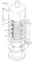
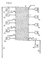
- FIG. 5 The experimental setup of Figures 5 and 6 corresponds to the block diagram of Figure 4, such so that the common reference numbers denote the same elements or means.
- a single metallic conduit 80 in the form of a serpentine gathering in continuity flow chambers 65, 62, 63 and 64, is arranged vertically inside an isolated chamber 81 thermally.
- Another coil 82 for traffic continuously a coolant is placed in the same room 81, in exchange for heat with duct 2 in the form of the coil 80, the turns of the coil 82 being wound adjacent to those of the serpentine 80.
- thermocouples 70 Do not enter inside the chamber 81 that the inlet tube 11a and the outlet tube 12b, different thermal probes 70, in the form of thermocouples and the electrical terminals corresponding to relay 51a and 51b, 55a and 55b, 53a and 53b, 54a and 54b, 52a and 52b.
- Electrical connection means establish connections with relays or aforementioned electrical connection terminals, to include the various confined portions 65, 62, 63 and 64, and the various conduit elements constituting the valves frozen, in a controlled way in a circuit electric, depending on the treatment process selected for the biological sample introduced by the tube inlet 11a, and discharged completely treated by the tube exit 12b.
- a strain of an S isolate. epidermis has been tested, with regard to its lysis, with the experimental set-up described with reference to FIGS. 5 and 6, but limited to a single treatment enclosure according to FIG. 2.
- a bacterial culture, having taken place the previous night, has was counted optically, and a dilution of the latter by a factor of ten was tried and analyzed, to search for the presence of nucleic acids, before and after lysis in the above-mentioned experimental setup.
- the experimental setup is brought to temperature ambient, 2 ml of the bacterial suspension to be tested are introduced into capillary line 2.
- the internal section of the duct is heated to 100 ° C for 5 seconds, while both ends 11 and 12 of the same duct remain frozen, and thus constitute two valves which delimit the enclosure or reaction chamber, that is to say of lysis.
- the section internal is again frozen for 5 seconds. After warming up to room temperature which is now become a lysate is recovered by evacuating it from conducted, and an analysis is carried out to detect the presence of nucleic acids.
- the reuse of the conduit for a new test requires molecular sterilization, or incineration, performed as follows: the duct is washed by introduction and passage of 3 ml of distilled water, then it is emptied and finally heated over its entire length to 400 ° C for 5 seconds.
- the analysis of the nucleic acids is carried out as follows: for a concentration of the order of 10 9 to 10 8 bacteria / 200 ⁇ l, the rRNA present in the corresponding lysate is hybridized in a VIDAS immunoassay device (brand recorded), using an eubacterial capture probe (S8L), and a conjugated detection probe (E2 20) labeled with alkaline phosphatase, and the hybridization signal is expressed in UFR (Relative Fluorescence Units).
- the rDNA present in the corresponding lysate was amplified by PCR, with the primers SPI-1 and SPI-4, and the PCR product was hybridized in a VIDAS device. , using the capture probe SPI-5, and the detection probe SPI-6.
- DNA oligonucleotide sequences are as follows:
- Hybridization steps in the VIDAS device were as follows: at the end of the lysis stage in the experimental setup, the lysate (200 ⁇ l or 10 ⁇ l) was placed in a polypropylene bar, comprising 10 wells, from the VIDAS device (BIOMERIEUX, Marcy l'Etoile, France). This bar was previously filled with all reagents required for hybridization, in separate wells: diluent, labeled probe, buffers hybridization and washing, and substrate. The bar loaded is placed in the drawers of the VIDAS device, and all the following steps of the hybridization protocol non-radioactive are performed automatically, during 1.5 hours at 37 ° C.
- the two oligonucleotides are used in a sandwich hybridization format, as described in document FR-A-2 663 040.
- An oligonucleotide is coated inside the solid surface of the end of the pipette, called Solid Phase Receptacle (SPR, brand recorded), and acts as a capture probe.
- SPR Solid Phase Receptacle
- a second oligonucleotide, covalently linked to phosphatase alkaline, is used as a detection probe, having for targets 16S rRNA, or PCR amplified rDNA.
- the enzyme catalyzes its transformation into a product fluorescent, namely 4-methylumbelliferone.
- the intensity of fluorescence in the cuvette is measured by the optical scanner of the VIDAS device, before and after contact with the SPR.
- the results are then analyzed automatically, and expressed in UFR units, thanks to the computerized interface.
- the test values are generated for each sample, by subtracting the blank value (reading of the substrate in the cuvette), of the fluorescence value of the sample. Values tests are compared with a threshold value, for give an interpretation which is then printed by the device. Test values below 200 UFR are considered negative results. Values tests greater than or equal to 200 UFR are considered as positive results, and thus demonstrate the presence of target nucleic acids (RNA or rDNA).
- the assembly of each assembly can be completely sterilized or decontaminated, opposite of any molecular species such as nucleic acid, after each treatment, in particular by passing a electric current, in the entire duct 2, by example of sampling means 71 at the entrance to the pump 73 according to the assembly of FIG. 4, and by therefore in all the valves according to the invention, and in all confined or pregnant portions elementary according to the invention.
Landscapes
- Engineering & Computer Science (AREA)
- General Engineering & Computer Science (AREA)
- Health & Medical Sciences (AREA)
- Chemical & Material Sciences (AREA)
- General Physics & Mathematics (AREA)
- Immunology (AREA)
- Mechanical Engineering (AREA)
- Physics & Mathematics (AREA)
- Life Sciences & Earth Sciences (AREA)
- Analytical Chemistry (AREA)
- Biochemistry (AREA)
- General Health & Medical Sciences (AREA)
- Pathology (AREA)
- Chemical Kinetics & Catalysis (AREA)
- Clinical Laboratory Science (AREA)
- Sampling And Sample Adjustment (AREA)
- Safety Valves (AREA)
- Infusion, Injection, And Reservoir Apparatuses (AREA)
- Apparatus Associated With Microorganisms And Enzymes (AREA)
- Resistance Heating (AREA)
- Details Of Valves (AREA)
- Measuring Or Testing Involving Enzymes Or Micro-Organisms (AREA)
- Centrifugal Separators (AREA)
- Electrical Discharge Machining, Electrochemical Machining, And Combined Machining (AREA)
Description
- un élément de conduit agencé pour recevoir ledit fluide dans la section de passage dudit conduit, dont la paroi est conductrice de la chaleur ;
- une seule et même source thermique consistant en un élément thermo-électrique à effet Peltier, disposé à l'extérieur de l'élément de conduit, générant de manière contrôlée et alternative de la chaleur et du froid ; cette source thermique est disposée au contact thermique, notamment en échange de chaleur avec ledit élément de conduit, pour passer alternativement et de manière contrôlée, selon la commande de l'élément thermo-électrique, d'un état froid dans lequel le fluide est susceptible par congélation de boucher de manière étanche le passage au travers dudit élément de conduit, à un état chaud dans lequel ledit fluide est liquéfié en libérant ledit passage.
- la source froide constitue ou est choisie comme une réserve frigorifique, immobile ou en mouvement, relativement importante par rapport à la quantité de froid nécessaire pour passer de l'état chaud à l'état froid de la vanne ;
- et la chaleur dissipée par effet ohmique dans l'élément de conduit est contrôlée à une valeur relativement importante, au moins égale à celle nécessaire pour annuler ou annihiler temporairement, et localement au niveau de la vanne, le froid transféré par la source froide vers l'élément de conduit, outre la chaleur nécessaire pour faire passer la vanne de l'état froid à l'état chaud.
- la figure 1 représente de manière schématique une vanne statique à congélation, selon l'invention ;
- la figure 2 représente un montage dans lequel est inclus une enceinte élémentaire de traitement selon l'invention ;
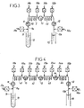
- les figures 3 et 4 représentent deux autres montages, combinant chacun plusieurs enceintes élémentaires de traitement selon l'invention ;
- les figures 5 et 6 représentent un montage expérimental ayant permis de tester les principes de la présente invention, montré en vue éclatée à la figure 5 et en schéma électrique à la figure 6.
- en congelant le fluide au travers du passage 2b, grâce à la source froide 3, pour obturer l'élément de conduit 2a, et par conséquent fermer le conduit 2 ;
- et en faisant passer un courant électrique 5 dans la masse de l'élément de conduit 2a, dissipant par effet ohmique de la chaleur, transférée directement au fluide, on fait fondre le fluide congelé au travers du passage 2b, en libérant ce dernier, et par conséquent en ouvrant la vanne.
- par actionnement de la pompe 73, et par le moyen de prélèvement 71, on aspire dans le conduit 2 un échantillon provenant notamment d'un prélèvement ou d'une culture cellulaire, remplissant notamment la portion confinée 2c ;
- on ferme successivement les vannes 12 et 11, de telle sorte que l'échantillon se trouve emprisonné entre les vannes 11 et 12 ;
- on fait passer un courant électrique entre les bornes 51b et 52b, de manière contrôlée, dans la portion confinée 2c, ce qui élève la température, et par conséquent la pression dans la zone 2c, et a pour conséquence de lyser les cellules contenues dans le fluide traité ;
- en ouvrant les vannes 11 et 12, on récupère l'échantillon traité.
- les vannes 11 et 12 étant ouvertes, on fait circuler un courant électrique dans la portion confinée 2c, de telle manière que le conduit 2 s'échauffe et se vide de son air ;
- on cesse cette circulation électrique, on ferme la vanne 12, et on refroidit le tube 2, de telle sorte qu'il se crée un vide partiel dans le tube 2, lequel a pour effet, si le moyen de prélèvement 71 est plongé dans un échantillon liquide dans le tube 72, de prélever par aspiration ledit échantillon, jusque dans la portion confinée de traitement 2c ;
- le traitement se poursuit alors comme précédemment, à partir de l'obturation de la vanne 11.
- aspiration et confinement d'un échantillon biologique dans l'enceinte 62, entre les deux vannes 15 et 13 fermées ;
- aspiration et confinement dans la zone 65 d'un autre fluide, en l'occurrence un liquide neutre comme de l'eau ou un tampon, entre les vannes 11 et 15 ;
- chauffage de l'enceinte 65, pour augmenter la pression du liquide neutre dans l'enceinte 65 ;
- fermeture de la vanne 14, et ouverture des vannes 13 et 15, de telle sorte que l'échantillon biologique est poussé au travers de la vanne 13, pourvue éventuellement d'un étranglement, par le liquide neutre de l'enceinte 65, de l'enceinte 62 à l'enceinte 63 ;
- aspiration et confinement dans l'enceinte 64, entre les vannes 14 et 12 fermées, d'un liquide neutre comme précédemment ; chauffage de ce liquide par passage d'un courant électrique dans l'enceinte 64 ;
- fermeture de la vanne 15 et ouverture des vannes 14 et 13, de telle sorte que l'échantillon biologique se trouve poussé au travers de la vanne 13, de l'enceinte 63 à l'enceinte 62, sous l'effet du liquide neutre sous haute pression, présent dans l'enceinte 64 ;
- et ainsi de suite, en considérant l'ouverture ou la fermeture appropriée des vannes précédemment et respectivement considérées.

| Méthode analytique | Inoculum de S. epidermis | Résultats d'hybridation (UFR) | |
| non lysé | lyse selon l'invention | ||
| 200 µl - | 10 9 | 640 | 6925 |
| hybridation de l'ARN naturel | 10 8 | 481 | 5512 |
| 10 µl - | 10 5 | 10 1 | 4234 |
| hybridation d'ADNr amplifié par PCT | 10 4 | 94 | 5898 |
| 10 3 | 98 | 7070 | |
| 10 2 | 98 | 10915 | |
| 10 | 94 | 7746 | |
| 1 | 96 | 2235 | |
| 0 | 75 | 185 |
Claims (20)
- Vanne (1) statique à congélation d'un fluide comprenant :caractérisée en ce que, en combinaison :un élément (2a) de conduit agencé pour recevoir ledit fluide dans la section de passage (2b), dont la paroi est conductrice de la chaleur ;au moins une source thermique générant de manière contrôlée de la chaleur et du froid, disposée au contact thermique, notamment en échange de chaleur avec ledit élément (2a) de conduit, pour passer d'un état froid, dans lequel le fluide est susceptible par congélation de boucher de manière étanche le passage (2a) au travers dudit élément de conduit, à un état chaud dans lequel ledit fluide est liquéfié ou vaporisé en libérant ledit passage ;(a) ledit élément de conduit (2a) est obtenu en un matériau, notamment métallique, mécaniquement résistant, susceptible de dissiper en son sein, de manière contrôlée, de la chaleur par effet ohmique, pour constituer une source chaude directement dans sa masse ;(b) une source froide (3), distincte de ladite source chaude, agencée et contrôlée pour générer uniquement du froid, demeure seule, à l'extérieur dudit élément (2a) de conduit, au contact thermique, notamment en échange de chaleur avec ledit élément de conduit.
- Vanne selon la revendication 1, caractérisée en ce que la source froide (3) constitue une réserve frigorifique relativement importante par rapport à la quantité de froid nécessaire pour passer de l'état chaud à l'état froid de ladite vanne, et la chaleur dissipée par effet ohmique dans l'élément de conduit est contrôlée à une valeur relativement importante, au moins égale à celle nécessaire pour annuler temporairement, et localement au niveau de ladite vanne, le froid transféré par la source froide vers ledit élément de conduit, lors du passage de l'état froid à l'état chaud de ladite vanne.
- Vanne selon la revendication 2, caractérisée en ce que l'élément de conduit (2a) est disposé dans une enceinte contenant un bain réfrigérant, formant la source froide (3).
- Vanne selon la revendication 2, caractérisée en ce que l'élément de conduit (2a) est disposé en échange de chaleur avec un conduit de circulation d'un liquide réfrigérant.
- Vanne selon la revendication 1, caractérisée en ce que le matériau métallique de l'élément de conduit (2a) est un alliage métallique.
- Vanne selon la revendication 1, caractérisée en ce que l'élément de conduit (2a) a une épaisseur comprise entre 1 µm et 50 mm, et préférentiellement entre 0,001 mm et 2 mm, et avantageusement entre 0,1 et 2 mm.
- Vanne selon la revendication 6, caractérisée en ce que l'élément de conduit (2a) a une section interne au plus égale à 50 mm, et préférentiellement comprise entre 0,001 mm et 2 mm.
- Enceinte (61) élémentaire allongée, équipée d'au moins une vanne selon l'une quelconque des revendications 1 à 5, caractérisée en ce que ladite enceinte est constituée d'une extrémité à l'autre par ledit conduit (2), ayant notamment la même section de passage selon toute sa longueur, dont au moins un élément (2a) associé à la fois à la source froide (3) et à une source électrique (5) constitue ladite vanne (11,12).
- Enceinte (61) selon la revendication 8, caractérisée en ce que l'élément (2a) de conduit appartenant à ladite vanne (11,12) est disposé à une extrémité dudit conduit.
- Enceinte (61) selon les revendications 8 et 9, caractérisée en ce que deux vannes (11,12) sont agencées aux deux extrémités dudit conduit respectivement, lesdites extrémités constituant les deux éléments de conduit (2a) des deux vannes (11,12) respectivement.
- Enceinte selon la revendication 8, caractérisée en ce que la source froide (3) et le ou les contacts électriques (5a,5b) avec l'élément de conduit (2a) appartenant à ladite vanne (11,12), sont agencés de manière mobile le long dudit conduit, moyennant quoi la vanne peut être déplacée selon la direction dudit conduit.
- Enceinte (61) selon la revendication 10, caractérisée en ce que une source électrique (51b,52b) est connectée à la portion (2c) de conduit, confinée, comprise entre les deux vannes (11,12), pour faire passer de manière contrôlée dans ladite portion un courant électrique, dissipant directement de la chaleur dans ledit conduit, par effet ohmique.
- Enceinte (61) selon la revendication 12, caractérisée en ce qu'une seule et même source électrique est connectée à la fois à la portion confinée (2c) de conduit, et à l'élément (2a) de conduit d'au moins une vanne (11,12), et des moyens de connexion électrique sont agencés pour faire passer un courant électrique dans ladite portion confinée et/ou ledit élément de conduit, de manière contrôlée, notamment selon toute séquence préétablie de branchements électriques élémentaires de ladite portion confinée et/ou dudit élément de conduit.
- Enceinte (61) selon la revendication 13, caractérisée en ce que les moyens de connexion électrique comprennent au moins un contact électrique avec ledit conduit (2), agencé de manière mobile selon la direction de ce dernier, pour inclure ladite portion confinée (2c) et/ou ledit élément de conduit (2a), de manière contrôlée, dans un circuit électrique.
- Enceinte (61) selon la revendication 13, caractérisée en ce que les moyens de connexion électrique comprennent une pluralité de bornes de connexion électrique, distribuées selon la direction du conduit, et des branchements électriques agencés avec lesdites bornes de connexion, pour inclure ladite portion confinée (2c) et/ou ledit élément de conduit (2a), de manière contrôlée dans un circuit électrique.
- Dispositif de traitement d'un échantillon du fluide, comprenant une enceinte (61) élémentaire selon l'une quelconque des revendications 8 à 15, caractérisé en ce que l'entrée (11a) d'une vanne statique (11) à congélation, amont selon le sens de circulation ou traitement dudit échantillon, est reliée à un moyen (71) de prélèvement dudit échantillon, et la sortie (12b) d'une autre vanne statique (12) à congélation, aval, est reliée à un moyen de circulation (73) dudit échantillon, par exemple une pompe.
- Application d'une enceinte élémentaire selon l'une quelconque des revendications 8 à 14, au traitement d'un échantillon dudit fluide, notamment d'un échantillon biologique, dans la portion confinée (2c) du conduit (2).
- Procédé de contrôle d'un courant fluide substantiellement monophasique, reçu dans un conduit (2), selon lequel, dans au moins une étape de contrôle, alternativement on congèle ledit fluide au travers du passage (2b) dans ledit conduit, pour obturer ce dernier, et on fait fondre ledit fluide congelé au travers du même dit passage, pour libérer ce dernier, caractérisé en ce que, pendant l'étape de contrôle, on fait fondre ledit fluide, en faisant passer un courant électrique (5) dans la masse du conduit, dissipant par effet ohmique de la chaleur, transférée directement audit fluide.
- Procédé de confinement d'un fluide monophasique, mettant en oeuvre au moins une étape de contrôle d'un courant dudit fluide selon la revendication 18, caractérisé en ce qu'on délimite une portion dudit conduit, formant zone (2c) de confinement, et à chacune des deux extrémités de ladite zone, on contrôle (11,12) le passage du fluide selon au moins une dite étape de contrôle de la revendication 18.
- Procédé selon la revendication 19, caractérisé en ce qu'on chauffe la zone (2c) de confinement, en faisant passer un courant électrique dans la masse du conduit, dissipant par effet ohmique de la chaleur, transférée directement audit fluide, lequel voit sa température et/ou sa pression augmenter, en relation avec la quantité de chaleur transférée.
Applications Claiming Priority (4)
| Application Number | Priority Date | Filing Date | Title |
|---|---|---|---|
| FR9501802A FR2730544A1 (fr) | 1995-02-13 | 1995-02-13 | Vanne statique a congelation, et enceinte de traitement controlee par au moins une vanne |
| FR9501802 | 1995-02-28 | ||
| FR9502541A FR2730545B1 (fr) | 1995-02-13 | 1995-02-28 | Vanne statique a congelation, et enceinte de traitement controlee par au moins une vanne |
| FR9502541 | 1995-02-28 |
Publications (2)
| Publication Number | Publication Date |
|---|---|
| EP0731303A1 EP0731303A1 (fr) | 1996-09-11 |
| EP0731303B1 true EP0731303B1 (fr) | 1999-09-01 |
Family
ID=26231763
Family Applications (1)
| Application Number | Title | Priority Date | Filing Date |
|---|---|---|---|
| EP19960420044 Expired - Lifetime EP0731303B1 (fr) | 1995-02-13 | 1996-02-13 | Vanne statique à congélation, et enceinte de traitement contrÔlée par au moins une telle vanne |
Country Status (7)
| Country | Link |
|---|---|
| US (1) | US5988197A (fr) |
| EP (1) | EP0731303B1 (fr) |
| JP (1) | JPH08297076A (fr) |
| AT (1) | ATE184082T1 (fr) |
| CA (1) | CA2169403A1 (fr) |
| DE (1) | DE69603999T2 (fr) |
| FR (1) | FR2730545B1 (fr) |
Cited By (1)
| Publication number | Priority date | Publication date | Assignee | Title |
|---|---|---|---|---|
| EP2279789A2 (fr) | 2009-07-30 | 2011-02-02 | Karlsruher Institut für Technologie | Dispositif de commande du débit de fluides à travers des canaux micro-fluidiques, son procédé de fonctionnement et d'utilisation |
Families Citing this family (25)
| Publication number | Priority date | Publication date | Assignee | Title |
|---|---|---|---|---|
| US6558901B1 (en) * | 1997-05-02 | 2003-05-06 | Biomerieux Vitek | Nucleic acid assays |
| IL124275A (en) * | 1997-05-02 | 2002-03-10 | Bio Merieux Vitek Inc | A method to produce sequences of nucleic acids |
| FR2764696B1 (fr) * | 1997-06-17 | 1999-08-13 | Inst Francais Du Petrole | Dispositif de prelevement d'echantillons de fluide comportant une vanne de controle a commande thermique |
| US6375901B1 (en) * | 1998-06-29 | 2002-04-23 | Agilent Technologies, Inc. | Chemico-mechanical microvalve and devices comprising the same |
| US6387234B1 (en) * | 1998-08-31 | 2002-05-14 | Iowa State University Research Foundation, Inc. | Integrated multiplexed capillary electrophoresis system |
| US6238613B1 (en) | 1999-07-14 | 2001-05-29 | Stratasys, Inc. | Apparatus and method for thermoplastic extrusion |
| US6578596B1 (en) * | 2000-04-18 | 2003-06-17 | Stratasys, Inc. | Apparatus and method for thermoplastic extrusion |
| JP3548858B2 (ja) * | 2001-01-22 | 2004-07-28 | 独立行政法人産業技術総合研究所 | 流量の制御方法及びそれに用いるマイクロバルブ |
| US6557575B1 (en) | 2001-11-19 | 2003-05-06 | Waters Investments Limited | Fluid flow control freeze/thaw valve for narrow bore capillaries or microfluidic devices |
| US6679279B1 (en) * | 2002-07-10 | 2004-01-20 | Motorola, Inc. | Fluidic valve having a bi-phase valve element |
| AU2003272397A1 (en) * | 2002-09-16 | 2004-04-30 | Waters Investments Limited | Freeze-thaw valve limiting cryogenic usage |
| DE10393861B4 (de) * | 2002-12-09 | 2016-12-15 | Waters Technologies Corp. (N.D.Ges.D. Staates Delaware) | Vorrichtung für eine Gefrier-Tau-Ventilschaltung und Verfahren zum Schalten eines Gefrier-Tau-Ventils |
| US7204264B2 (en) * | 2004-04-21 | 2007-04-17 | Waters Investments Ltd. | High pressure capillary micro-fluidic valve device and a method of fabricating same |
| US7694694B2 (en) * | 2004-05-10 | 2010-04-13 | The Aerospace Corporation | Phase-change valve apparatuses |
| US8642353B2 (en) * | 2004-05-10 | 2014-02-04 | The Aerospace Corporation | Microfluidic device for inducing separations by freezing and associated method |
| US7686040B2 (en) * | 2004-06-24 | 2010-03-30 | The Aerospace Corporation | Electro-hydraulic devices |
| US7650910B2 (en) * | 2004-06-24 | 2010-01-26 | The Aerospace Corporation | Electro-hydraulic valve apparatuses |
| US7721762B2 (en) * | 2004-06-24 | 2010-05-25 | The Aerospace Corporation | Fast acting valve apparatuses |
| GB201003614D0 (en) * | 2010-03-04 | 2010-04-21 | Airbus Operations Ltd | Water drain tool |
| NL1037976C2 (nl) * | 2010-05-21 | 2011-11-22 | Vorscon Holding B V | Verbeterd veiligheidssysteem voor gevaarlijke stoffen. |
| FR2988471B1 (fr) * | 2012-03-21 | 2014-05-09 | Commissariat Energie Atomique | Dispositif de prise de pression optimisee pour canaux chauffants |
| US8813816B2 (en) | 2012-09-27 | 2014-08-26 | Apple Inc. | Methods of melting and introducing amorphous alloy feedstock for casting or processing |
| US8968617B2 (en) * | 2012-11-12 | 2015-03-03 | Spirit Aerosystems, Inc. | Thermo-rheological fluid valve for resin infusion |
| WO2017015529A1 (fr) | 2015-07-22 | 2017-01-26 | The University Of North Carolina At Chapel Hill | Dispositifs fluidiques à soupapes de congélation-décongélation à agents de nucléation de glace et procédés associés de mise en œuvre et d'analyse |
| CN114377744B (zh) * | 2022-01-25 | 2023-04-21 | 威乐(中国)水泵系统有限公司 | 一种水泵模拟环境多功能测试台 |
Family Cites Families (11)
| Publication number | Priority date | Publication date | Assignee | Title |
|---|---|---|---|---|
| US338447A (en) * | 1886-03-23 | Method of and apparatus for regulating the temperature of a substance passing | ||
| US3712322A (en) * | 1970-07-06 | 1973-01-23 | Burroughs Corp | Apparatus for varying the flow rate of gas into a vacuum system |
| US4082109A (en) * | 1976-09-03 | 1978-04-04 | Hughes Aircraft Company | Heat pipe actuated valve |
| US4203472A (en) * | 1978-06-20 | 1980-05-20 | Dulaney Burrell C | Device for stopping fluid flow from a pipe |
| FI70331C (fi) * | 1985-04-12 | 1986-09-15 | Fluilogic Systems Oy | Foerfarande foer framstaellning av till en behandlingsenhet for vaetskemaengd hoerande genom nedfrysning staengbara kra na samt genom foerfarande framstaelld behandlingsenhet |
| DE3837604A1 (de) * | 1988-11-05 | 1990-05-10 | Lumen Gmbh | Vorrichtung zum herstellen von speiseeis, milchshake, sorbet, gefrorenen suessspeisen u. dgl. jeweils aus einem pumpfaehigen ansatz |
| JPH0814337B2 (ja) * | 1988-11-11 | 1996-02-14 | 株式会社日立製作所 | 流体自体の相変化を利用した流路の開閉制御弁及び開閉制御方法 |
| JP3028826B2 (ja) * | 1990-03-09 | 2000-04-04 | 株式会社日立製作所 | 流体流路の開閉装置及びその開閉制御方法及び閉止確認方法 |
| FR2663040B1 (fr) * | 1990-06-11 | 1995-09-15 | Bio Merieux | Procede de detection d'une sequence nucleotidique selon la technique d'hybridation sandwich. |
| SE9300907L (sv) * | 1993-03-18 | 1994-04-18 | Lothar Beise | Sätt och anordning för bildande av propp i rör |
| DE4336283A1 (de) * | 1993-10-25 | 1995-04-27 | Schenck Ag Carl | Ventil für strömende Medien |
-
1995
- 1995-02-28 FR FR9502541A patent/FR2730545B1/fr not_active Expired - Fee Related
-
1996
- 1996-02-12 US US08/598,607 patent/US5988197A/en not_active Expired - Fee Related
- 1996-02-13 EP EP19960420044 patent/EP0731303B1/fr not_active Expired - Lifetime
- 1996-02-13 CA CA 2169403 patent/CA2169403A1/fr not_active Abandoned
- 1996-02-13 DE DE69603999T patent/DE69603999T2/de not_active Expired - Fee Related
- 1996-02-13 AT AT96420044T patent/ATE184082T1/de not_active IP Right Cessation
- 1996-02-13 JP JP6157896A patent/JPH08297076A/ja active Pending
Cited By (3)
| Publication number | Priority date | Publication date | Assignee | Title |
|---|---|---|---|---|
| EP2279789A2 (fr) | 2009-07-30 | 2011-02-02 | Karlsruher Institut für Technologie | Dispositif de commande du débit de fluides à travers des canaux micro-fluidiques, son procédé de fonctionnement et d'utilisation |
| DE102009035292A1 (de) | 2009-07-30 | 2011-02-03 | Karlsruher Institut für Technologie | Vorrichtung zum Steuern des Durchflusses von Fluiden durch mikrofluidische Kanäle, Verfahren zu ihrem Betrieb und ihre Verwendung |
| US8480974B2 (en) | 2009-07-30 | 2013-07-09 | Karlsruher Institut Fuer Technologie | Device for controlling the flow of fluids through microfluidic channels |
Also Published As
| Publication number | Publication date |
|---|---|
| EP0731303A1 (fr) | 1996-09-11 |
| US5988197A (en) | 1999-11-23 |
| ATE184082T1 (de) | 1999-09-15 |
| CA2169403A1 (fr) | 1996-08-14 |
| DE69603999D1 (de) | 1999-10-07 |
| FR2730545B1 (fr) | 1997-03-28 |
| JPH08297076A (ja) | 1996-11-12 |
| DE69603999T2 (de) | 1999-12-23 |
| FR2730545A1 (fr) | 1996-08-14 |
Similar Documents
| Publication | Publication Date | Title |
|---|---|---|
| EP0731303B1 (fr) | Vanne statique à congélation, et enceinte de traitement contrÔlée par au moins une telle vanne | |
| US10281375B2 (en) | In situ heat induced antigen recovery and staining method | |
| EP3254762B1 (fr) | Procédés, systèmes et dispositifs de détection et d'identification de micro-organismes dans des échantillons de culture microbiologique | |
| US9217696B2 (en) | Ultra-rapid diagnostic tissue preparation as an alternative to frozen section | |
| US4617102A (en) | Process and apparatus for purifying and concentrating DNA from crude mixtures containing DNA | |
| EP0379437B1 (fr) | Procédé et dispositif de régulation rapide d'une température de paroi | |
| WO2005040763A1 (fr) | Traitement tissulaire simplifie | |
| EP1313973A1 (fr) | Carte reactionnelle et utilisation d'une telle carte | |
| LU87782A1 (fr) | Appareil destine a l'execution automatique et repetee d'un cycle thermique pour le traitement d'echantillons biologiques | |
| CA2228737A1 (fr) | Carte d'analyse a usage unique comprenant un conduit d'ecoulement de liquides | |
| EP3766580A1 (fr) | Dispositif micro-fluidique de préparation et d'analyse d'un échantillon biologique | |
| EP1515794A1 (fr) | DISPOSITIF FLUIDIQUE PERMETTANT DE MANIERE THERMO-PNEUMATIQUE L'ISOLEMENT ET EVENTUELLEMENT L AGITATION DU CONTENU D&apo s;UNE CAVITE OPERATOIRE | |
| EP0803056A1 (fr) | Ensemble de traitement d'un echantillon en milieu liquide, notamment d'un materiel biologique | |
| FR2808089A1 (fr) | Dispositif perfectionne d'analyse d'echantillons par electrophorese multicapillaire a thermo-regulation solide/solide | |
| FR2730544A1 (fr) | Vanne statique a congelation, et enceinte de traitement controlee par au moins une vanne | |
| EP3443322A1 (fr) | Procédé et système de récupération de produits d'une émulsion | |
| EP1187678A1 (fr) | Dispositif de mise en oeuvre d'une carte d'analyse, carte d'analyse et procede les mettant en oeuvre | |
| EP1604038B1 (fr) | Installation automatisee pour la detection de la fixation de biomolecules sur un echantillon en trois dimensions | |
| Sartor | Cryogenic Single-Molecule Active Control Microscopy with Fluorescent Proteins | |
| FR2897872A1 (fr) | Procede d'analyse microbiologique rapide. | |
| CA2198668A1 (fr) | Incubateur portatif pour detection de la mammite | |
| Kuzu et al. | Identification of bone marrow derived nonhematopoietic cells by double labeling with immunohistochemistry and in situ hybridization |
Legal Events
| Date | Code | Title | Description |
|---|---|---|---|
| PUAI | Public reference made under article 153(3) epc to a published international application that has entered the european phase |
Free format text: ORIGINAL CODE: 0009012 |
|
| 17P | Request for examination filed |
Effective date: 19960216 |
|
| AK | Designated contracting states |
Kind code of ref document: A1 Designated state(s): AT BE CH DE DK ES FR GB GR IE IT LI LU MC NL PT SE |
|
| GRAG | Despatch of communication of intention to grant |
Free format text: ORIGINAL CODE: EPIDOS AGRA |
|
| 17Q | First examination report despatched |
Effective date: 19990323 |
|
| GRAG | Despatch of communication of intention to grant |
Free format text: ORIGINAL CODE: EPIDOS AGRA |
|
| GRAH | Despatch of communication of intention to grant a patent |
Free format text: ORIGINAL CODE: EPIDOS IGRA |
|
| GRAH | Despatch of communication of intention to grant a patent |
Free format text: ORIGINAL CODE: EPIDOS IGRA |
|
| GRAA | (expected) grant |
Free format text: ORIGINAL CODE: 0009210 |
|
| AK | Designated contracting states |
Kind code of ref document: B1 Designated state(s): AT BE CH DE DK ES FR GB GR IE IT LI LU MC NL PT SE |
|
| PG25 | Lapsed in a contracting state [announced via postgrant information from national office to epo] |
Ref country code: SE Free format text: THE PATENT HAS BEEN ANNULLED BY A DECISION OF A NATIONAL AUTHORITY Effective date: 19990901 Ref country code: NL Free format text: LAPSE BECAUSE OF FAILURE TO SUBMIT A TRANSLATION OF THE DESCRIPTION OR TO PAY THE FEE WITHIN THE PRESCRIBED TIME-LIMIT Effective date: 19990901 Ref country code: GR Free format text: LAPSE BECAUSE OF NON-PAYMENT OF DUE FEES Effective date: 19990901 Ref country code: AT Free format text: LAPSE BECAUSE OF FAILURE TO SUBMIT A TRANSLATION OF THE DESCRIPTION OR TO PAY THE FEE WITHIN THE PRESCRIBED TIME-LIMIT Effective date: 19990901 |
|
| REF | Corresponds to: |
Ref document number: 184082 Country of ref document: AT Date of ref document: 19990915 Kind code of ref document: T |
|
| REG | Reference to a national code |
Ref country code: CH Ref legal event code: EP |
|
| REF | Corresponds to: |
Ref document number: 69603999 Country of ref document: DE Date of ref document: 19991007 |
|
| REG | Reference to a national code |
Ref country code: IE Ref legal event code: FG4D Free format text: FRENCH |
|
| PG25 | Lapsed in a contracting state [announced via postgrant information from national office to epo] |
Ref country code: DK Free format text: LAPSE BECAUSE OF FAILURE TO SUBMIT A TRANSLATION OF THE DESCRIPTION OR TO PAY THE FEE WITHIN THE PRESCRIBED TIME-LIMIT Effective date: 19991201 |
|
| PG25 | Lapsed in a contracting state [announced via postgrant information from national office to epo] |
Ref country code: PT Free format text: LAPSE BECAUSE OF FAILURE TO SUBMIT A TRANSLATION OF THE DESCRIPTION OR TO PAY THE FEE WITHIN THE PRESCRIBED TIME-LIMIT Effective date: 19991202 |
|
| GBT | Gb: translation of ep patent filed (gb section 77(6)(a)/1977) |
Effective date: 19991221 |
|
| REG | Reference to a national code |
Ref country code: CH Ref legal event code: NV Representative=s name: KIRKER & CIE SA |
|
| PG25 | Lapsed in a contracting state [announced via postgrant information from national office to epo] |
Ref country code: IE Free format text: LAPSE BECAUSE OF NON-PAYMENT OF DUE FEES Effective date: 20000119 |
|
| ITF | It: translation for a ep patent filed | ||
| NLV1 | Nl: lapsed or annulled due to failure to fulfill the requirements of art. 29p and 29m of the patents act | ||
| PGFP | Annual fee paid to national office [announced via postgrant information from national office to epo] |
Ref country code: ES Payment date: 20000209 Year of fee payment: 5 |
|
| PLBE | No opposition filed within time limit |
Free format text: ORIGINAL CODE: 0009261 |
|
| 26N | No opposition filed | ||
| REG | Reference to a national code |
Ref country code: IE Ref legal event code: FD4D |
|
| REG | Reference to a national code |
Ref country code: GB Ref legal event code: IF02 |
|
| PGFP | Annual fee paid to national office [announced via postgrant information from national office to epo] |
Ref country code: FR Payment date: 20040126 Year of fee payment: 9 |
|
| PGFP | Annual fee paid to national office [announced via postgrant information from national office to epo] |
Ref country code: LU Payment date: 20040128 Year of fee payment: 9 |
|
| PGFP | Annual fee paid to national office [announced via postgrant information from national office to epo] |
Ref country code: GB Payment date: 20040130 Year of fee payment: 9 |
|
| PGFP | Annual fee paid to national office [announced via postgrant information from national office to epo] |
Ref country code: MC Payment date: 20040217 Year of fee payment: 9 |
|
| PGFP | Annual fee paid to national office [announced via postgrant information from national office to epo] |
Ref country code: BE Payment date: 20040312 Year of fee payment: 9 |
|
| PGFP | Annual fee paid to national office [announced via postgrant information from national office to epo] |
Ref country code: DE Payment date: 20040331 Year of fee payment: 9 |
|
| PGFP | Annual fee paid to national office [announced via postgrant information from national office to epo] |
Ref country code: CH Payment date: 20040506 Year of fee payment: 9 |
|
| PG25 | Lapsed in a contracting state [announced via postgrant information from national office to epo] |
Ref country code: LU Free format text: LAPSE BECAUSE OF NON-PAYMENT OF DUE FEES Effective date: 20050213 Ref country code: IT Free format text: LAPSE BECAUSE OF NON-PAYMENT OF DUE FEES Effective date: 20050213 Ref country code: GB Free format text: LAPSE BECAUSE OF NON-PAYMENT OF DUE FEES Effective date: 20050213 |
|
| PG25 | Lapsed in a contracting state [announced via postgrant information from national office to epo] |
Ref country code: MC Free format text: LAPSE BECAUSE OF NON-PAYMENT OF DUE FEES Effective date: 20050228 Ref country code: LI Free format text: LAPSE BECAUSE OF NON-PAYMENT OF DUE FEES Effective date: 20050228 Ref country code: CH Free format text: LAPSE BECAUSE OF NON-PAYMENT OF DUE FEES Effective date: 20050228 Ref country code: BE Free format text: LAPSE BECAUSE OF NON-PAYMENT OF DUE FEES Effective date: 20050228 |
|
| BERE | Be: lapsed |
Owner name: *BIO MERIEUX Effective date: 20050228 |
|
| PG25 | Lapsed in a contracting state [announced via postgrant information from national office to epo] |
Ref country code: DE Free format text: LAPSE BECAUSE OF NON-PAYMENT OF DUE FEES Effective date: 20050901 |
|
| GBPC | Gb: european patent ceased through non-payment of renewal fee |
Effective date: 20050213 |
|
| REG | Reference to a national code |
Ref country code: CH Ref legal event code: PL |
|
| PG25 | Lapsed in a contracting state [announced via postgrant information from national office to epo] |
Ref country code: FR Free format text: LAPSE BECAUSE OF NON-PAYMENT OF DUE FEES Effective date: 20051031 |
|
| REG | Reference to a national code |
Ref country code: FR Ref legal event code: ST Effective date: 20051031 |
|
| BERE | Be: lapsed |
Owner name: *BIO MERIEUX Effective date: 20050228 |
|
| PG25 | Lapsed in a contracting state [announced via postgrant information from national office to epo] |
Ref country code: ES Free format text: LAPSE BECAUSE OF NON-PAYMENT OF DUE FEES Effective date: 20010228 |