EP0730907A2 - Transfer port system - Google Patents
Transfer port system Download PDFInfo
- Publication number
- EP0730907A2 EP0730907A2 EP96301569A EP96301569A EP0730907A2 EP 0730907 A2 EP0730907 A2 EP 0730907A2 EP 96301569 A EP96301569 A EP 96301569A EP 96301569 A EP96301569 A EP 96301569A EP 0730907 A2 EP0730907 A2 EP 0730907A2
- Authority
- EP
- European Patent Office
- Prior art keywords
- doors
- door
- sterile
- transfer port
- door frames
- Prior art date
- Legal status (The legal status is an assumption and is not a legal conclusion. Google has not performed a legal analysis and makes no representation as to the accuracy of the status listed.)
- Granted
Links
Images


Classifications
-
- F—MECHANICAL ENGINEERING; LIGHTING; HEATING; WEAPONS; BLASTING
- F26—DRYING
- F26B—DRYING SOLID MATERIALS OR OBJECTS BY REMOVING LIQUID THEREFROM
- F26B5/00—Drying solid materials or objects by processes not involving the application of heat
- F26B5/04—Drying solid materials or objects by processes not involving the application of heat by evaporation or sublimation of moisture under reduced pressure, e.g. in a vacuum
- F26B5/06—Drying solid materials or objects by processes not involving the application of heat by evaporation or sublimation of moisture under reduced pressure, e.g. in a vacuum the process involving freezing
-
- B—PERFORMING OPERATIONS; TRANSPORTING
- B01—PHYSICAL OR CHEMICAL PROCESSES OR APPARATUS IN GENERAL
- B01L—CHEMICAL OR PHYSICAL LABORATORY APPARATUS FOR GENERAL USE
- B01L1/00—Enclosures; Chambers
- B01L1/02—Air-pressure chambers; Air-locks therefor
Landscapes
- Health & Medical Sciences (AREA)
- Engineering & Computer Science (AREA)
- Chemical Kinetics & Catalysis (AREA)
- Chemical & Material Sciences (AREA)
- Life Sciences & Earth Sciences (AREA)
- Molecular Biology (AREA)
- Clinical Laboratory Science (AREA)
- Mechanical Engineering (AREA)
- General Engineering & Computer Science (AREA)
- Apparatus For Disinfection Or Sterilisation (AREA)
- Drying Of Solid Materials (AREA)
- Control And Other Processes For Unpacking Of Materials (AREA)
- Automatic Analysis And Handling Materials Therefor (AREA)
- Float Valves (AREA)
- Packages (AREA)
Abstract
two door frames connected to the environments and two doors connected to the two door frames so that when the two sterile environments are in the docked position, the two door frames and the two doors are juxtaposed and in close physical contact with one another and when the two sterile environments are in the undocked position, the two door frames are spaced apart from one another and the two doors seal the two sterile environments;
the two door frames and doors having a potentially non-sterile peripheral juncture located at an outer periphery of the two doors when in their juxtaposition;
door connection means for connecting the two doors to one another when the two sterile environments are in the docked position;
opening means for opening the transfer port, the opening means having means for moving the doors when connected to one another between a closed position sealing the two sterile environments and an open position away from the two door frames permitting transport through the two door frames and between the two sterile environments; and
heating means for heating and thereby sterilising the potentially non-sterile peripheral juncture.
Description
- This invention relates to a transfer port system for transferring articles between two sterile environments that are adapted to be brought into close proximity to one another by a docking operation. More particularly, the invention relates to such a transfer port system in which one or both of the sterile environments is also a vacuum environment such as a freeze drier and the other of the sterile environments is an isolation chamber surrounding a loading cart designed to dock with the freeze drier.
- Many industrial processes require the maintenance of clean sterile conditions during product manufacture and packaging. This requirement is nowhere greater than in the pharmaceutical industry in which products are manufactured and packaged under predefined conditions of sterility in order to prevent bacterial contamination. In the packaging of pharmaceutical products, vials are washed and are then conveyed through a sterilising tunnel to a filling machine which provides a sterile environment to fill the vials with product and to loosely cap the vials with stoppers. Afterward, the vials travel to a clean room where they are accumulated on an accumulation table. The vials are then loaded on a loading cart, a motorised vehicle designed to convey the vials to a portal of a freeze drier projecting into the clean room. The loading cart has a sliding table that projects into the freeze drier portal to allow the vials to be shifted to the freeze drier shelves. Each freeze drier shelf is raised into a loading position, loaded and raised to raise the next underlying shelf into the loading position. At the conclusion of the freeze drying operation a hydraulic ram within the freeze drier packs the stoppers into the vials.
- As can be appreciated, the maintenance of a clean room is an expensive proposition. Moreover, the workers must be clothed in clean suits which are uncomfortable and require them to leave the clean room for relaxation and relief.
- The invention provides a transfer port system that is particularly suitable for use in providing a sterile interface between an accumulation table and a loading cart and also a sterile interface between the loading cart and a freeze drier in order to eliminate the clean room. The invention is not limited to freeze drying applications.
- In accordance with the invention, there is provided a transfer port between two sterile environments having docked and undocked positions, the door mechanism comprising:
- two door frames connected to the environments and two doors connected to the two door frames so that when the two sterile environments are in the docked position, the two door frames and the two doors are juxtaposed and in close physical contact with one another and when the two sterile environments are in the undocked position, the two door frames are spaced apart from one another and the two doors seal the two sterile environments;
- the two door frames and doors having a potentially non-sterile peripheral juncture located at an outer periphery of the two doors when in their juxtaposition;
- door connection means for connecting the two doors to one another when the two sterile environments are in the docked position;
- opening means for opening the transfer port, the opening means having means for moving the doors when connected to one another between a closed position sealing the two sterile environments and an open position away from the two door frames permitting transport through the two door frames and between the two sterile environments; and
- heating means for heating and thereby sterilising the potentially non-sterile peripheral juncture.
- Preferably also, the door connection means has means for producing a vacuum between the two doors or an electromagnetic coupling between the two doors.
- Preferably the heating means can comprise at least one of the two door frames having internal channels for circulation of the heat transfer fluid to heat the two door frames and the two doors and thereby to sterilise the potentially non-sterile peripheral juncture. In such heating means, an inlet and an outlet to the internal peripheral channel is preferably provided for introducing the heat transfer fluid into the internal peripheral channel and for discharging the heat transfer fluid from the internal peripheral channel respectively.
- The use of the heat transfer fluid permits temperatures within the potentially non-sterile peripheral juncture to be maintained in a range of between about 150°C. and about 300°C for long periods of time. This will generally guarantee terminal sterilisation. In an application of the invention involving freeze driers, the heat transfer fluid can be formed from diathermic fluid that is being used to heat freeze drier shelves during the freeze drier process. Hence, the transfer port of the invention, although not limited to applications involving the use of freeze driers, can be very advantageously utilised in connection with pharmaceutical manufacturing employing freeze driers in the preparation and packaging of product.
- For a better understanding of the invention, reference will now be made, by way of exemplification only, to the accompanying drawings in which:
- Figure 1 is a fragmentary, cross-sectional view of a freeze drier and loading cart employing a docking port system in accordance with the invention with the sterile environments of the freeze drier and the loading cart shown in their undocked position;
- Figure 2 is a fragmentary, cross-sectional view of the freeze drier and loading cart shown in Figure 1 in the docked position;
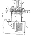
- Figure 3 is a fragmentary, cross-sectional view of the freeze drier and loading cart in the docked position shown in Figure 2 and with doors in an open position to allow transfer of articles through the transfer port;
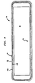
- Figure 4 is a front elevational view of a door used in the transfer port system of the present invention; and
- Figure 5 is an enlarged fragmentary view of Figure 1 illustrating an outer vacuum door in accordance with the invention.
- With reference to Figure 1, a
transfer port system 1 in accordance with the invention is illustrated as being applied to afreeze drier 2 having an internalsterile environment 3 and a loading cart 4. The loading cart 4 is surrounded by anisolation chamber 5 to provide asterile environment 6. The base structure of loading cart 4, also not illustrated, would project through anisolation chamber 5 and would be sealed at the locations at which theisolation chamber 5 were penetrated by such base structure so as to maintain asterile environment 6. With additional reference to Figure 2, the loading cart 4 is a conventional loading cart and is designed so that thesterile environment 6 can assume the docked position with the internalsterile environment 3 of thefreeze drier 2. As illustrated, the loading cart 4 holds trays ofvials 7 to be loaded ontofreeze drier shelves 8 on an extensible orsliding table portion 9. Thetable portion 9 is designed to extend intofreeze drier 2 to accomplish the loading in a known manner. - The
vials 8 are retrieved from an accumulation table having an isolated environment and a door system, which although not shown, would include an isolated environment such as the type of environment provided by theisolation chamber 5 and a door system sharing similar components to those used in connection withfreeze drier 2. The environment used with the accumulation table allows transfer ofvials 8 from the sterile environment of the accumulation table to the sterile environment provided by theisolation chamber 5 of the loading cart 4 under predetermined sterile conditions. Thereafter,vials 8 are again transferred from the loading cart 4 and theisolation chamber 5 to the internalsterile environment 3 of thefreeze drier 2, again, under such predetermined sterile conditions. As such, there is no need for a clean room to be provided for the loading cart 4 to travel between the accumulation table and thefreeze drier 2. - The
transfer port system 1 is provided with twodoor frames freeze drier 2 and theisolation chamber 5. Twodoors door frames door frames doors door frames doors doors sterile environments door frames doors doors - With reference to Figure 3, a
surface 18 of thedoor 14 and asurface 20 of thedoor 16 are sterile surfaces because they are located within thesterile environments peripheral surfaces door 14 and thedoor frame 10, respectively, andperipheral surfaces door 16 and thedoor frame 12, respectively, are sterile surfaces as well. The juxtaposed surfaces of thedoors recessed surfaces chamber 34 having avacuum inlet 35 which will be discussed hereinafter. These aforementioned surfaces, although not sterile, are in close physical contact when thesterile environments outer juncture 36 between thedoors inner juncture 37 of thedoor frames doors door frames doors peripheral band 38 at thedoor frames doors 13 and 16 is formed that is potentially not sterile. - In order to sterilise this peripheral band of non-sterility,
peripheral channels 39 are provided for circulating a heat transfer fluid in thedoor frame 10. Since thedoor frame 10 is of rectangular configuration, horizontal segments of theperipheral channels 39 which are illustrated in cross-section in Figures 1 and 2 would communicate with vertical segments of theperipheral channels 39. The transfer fluid enters theperipheral channels 39 through afluid inlet 40 and is discharged from theperipheral channels 39 via afluid outlet 42. As could be appreciated, theperipheral channels 39 could be provided in thedoor frame 12 but not in thedoor frame 10 or alternatively, peripheral channels such as theperipheral channels 39 could be provided in both thedoor frames doors door frame 10 and thedoor 14 thereof. A source of heat transfer fluid would be provided for sterilisation purposes mentioned above. - When the
sterile environments doors chamber 34 through thevacuum inlet 35. Although not shown, a vacuum line would lead to the vacuum supply offreeze drier 2. In order to draw a vacuum inchamber 34, a peripheralvacuum sealing gasket 44 is provided for thedoor 14 and a similar peripheralvacuum sealing gasket 46 is provided for thedoor frame 12. The application of vacuum holds thedoors vials 8 through thedoor frames transfer port system 1. In a proper application of the invention, a mechanical latching mechanism or an electromagnetic latching mechanism could be used in place of the vacuum system, described above, to hold doors against one another. In this regard, the electromagnetic latching mechanism could comprise electromagnets recessed in one of thedoors doors 14 and 16 (if doors are made from a weak or non-ferromagnetic material) to be attracted by the electromagnets and thus hold the doors together. - A peripheral
vacuum sealing gasket 44 hasadjacent sealing surfaces 44A and 44B set within theperipheral surfaces 22 and of thedoor 14 and the front surface portions of thedoor 14 to seal against the peripheral surfaces of thedoor frame 10 and the front surface portions of thedoor 16. Similarly, a peripheralvacuum sealing gasket 46 has sealingsurfaces 46A and 46B set within theperipheral surfaces 28 of thedoor frame 12 and the front surface portions thereof to seal against theperipheral surfaces 26 of thedoor 16 and the front surface portions of thedoor frame 12. In cross-section, theperipheral sealing gaskets peripheral band 38 of non-sterility that must be sterilised in order to ensure and maintain sterile conditions withintransfer port system 1. Thevacuum sealing gaskets doors doors - The
door 16 is held in place and released from thedoor frame 12 by means that can comprise a system of latchingpins 48 which are activated by adouble acting solenoid 50 having anactuating arm 52 acting within a welded steel bellows 54. Theactuating arm 52 acts against acrown piece 56 that is connected to thebellows 54 and theactuating arm 52. The latchingpin 48 is in turn connected to thecrown piece 56, for example by welding. Aguide 58 is provided to guide the latchingpin 48 into alatch member 60 connected to thedoor 16. It is to be noted that both thelatch member 60 and adistal end 62 of the latchingpin 48 are wedge shaped. The angles of these wedges are not equal so that when thedistal end 62 of the latchingpin 48 is seated within the latchingmember 60, thedoor 16 is driven inwardly of thedoor frame 12 to produce a hermetic seal. - The
door 14 is held in position by amotorised hinge mechanism 64 which has a pivotable L-shapedlug 66 connected to thedoor 14 and astationary lug 68 connected to thedoor frame 10. Two or more set of such hinge mechanisms would be used to support thedoor 14 in both the closed and open positions thereof and for pivoting thedoor 14 between such positions. A motor drivenshaft 70 rotates within thestationary lug 68 and is further attached to the pivotable L-shapedlug 66 to move thedoor 14 between closed and open positions. - When the
sterile environments chamber 34 causing thedoors solenoids 50 are activated to move the latching pins 48 outwardly so that thedistal end 62 of thepins 48 unseats from the latchingmembers 60. Thereafter, the motor drivenshaft 70 rotates in a counterclockwise direction of rotation pivoting thedoors vials 7 onto theshelves 8. - With further reference now to Figure 4, it is to be noted that, when the
sterile environments doors vacuum sealing gaskets doors door frames doors doors door frames - Referring to Figure 5, where one of these sterile environments is also a vacuum environment such as in a freeze drier, an
outer vacuum door 72 can be utilised. Thevacuum door 72 is hinged by ahinge mechanism 74 to an outer frame-like member 76 and is latched in place against the outer frame-like member 76 via alatching mechanism 78 which is activated via a hydraulic actuator, only the actuatingrod 80 of which is illustrated in the figures. The frame-like member 76 is provided with a vacuum 'O'ring sealing gasket 82 that surrounds thedoor frame 10 to produce a vacuum seal surrounding thedoor frame 10 anddoor 14. - The
vacuum door 72 has a layered construction formed by acentral plate 84 and opposed inner andouter plates ribs 90 separate theinner plate 86 from thecentral plate 84 and the plurality ofribs 92 separate theouter plate 88 from thecentral plate 84. The aforementioned ribs and plates are constructed with the ribs having an interlocking construction of two elements which can be separately welded to the plates and then interlocked during final assembly. Theribs 90 are staggered in a direction normal to the illustration so that an inner layer of thevacuum door 72 can act as a heat exchanger to circulate diathermic fluid (or other heat transfer fluid in case of other applications of transfer port system 1) through the inner layer of thevacuum door 72. To this end, the formed heat exchanger has aninlet 94 and anoutlet 96. The outer layer formed between theouter plates 88 and thecentral plate 84 is vacuum sealed to provide vacuum insulation and protection of workmen passing thetransfer port system 1 when loading the cart 4 and therefore thesterile environments ribs 92 can be staggered in a direction normal to the illustration for this purpose.
Claims (10)
- A transfer port between two sterile environments having docked and undocked positions, the transfer port comprising:two door frames connected to the environments and two doors connected to the two door frames so that when the two sterile environments are in the docked position, the two door frames and the two doors are juxtaposed and in close physical contact with one another and when the two sterile environments are in the undocked position, the two door frames are spaced apart from one another and the two doors seal the two sterile environments;the two door frames and doors having a potentially non-sterile peripheral juncture located at an outer periphery of the two doors when in their juxtaposition;door connection means for connecting the two doors to one another when the two sterile environments are in the docked position;opening means for opening the transfer port, the opening means having means for moving the doors when connected to one another between a closed position sealing the two sterile environments and an open position away from the two door frames permitting transport through the two door frames and between the two sterile environments; andheating means for heating and thereby sterilising the potentially non-sterile peripheral juncture.
- A transfer port according to Claim 1 in which the heating means comprises at least one of the two door frames having internal channels for circulation of a heat transfer fluid to heat the two door frames and the two doors and thereby sterilise the potentially non-sterile peripheral juncture, an inlet and an outlet to the internal peripheral channels for introducing the heat transfer fluid into the internal peripheral channels and for discharging the heat transfer fluid from the internal peripheral channels, respectively.
- A transfer port according to Claim 1 or Claim 2 in which the door connection means has means for producing a vacuum between the two doors or an electromagnetic coupling between the two doors.
- A transfer port according to any preceding claim in which the door connection means comprises:the two doors having central recessed surfaces forming a chamber between the two doors during the docked position of the two sterile environments;vacuum sealing means surrounding said chamber for forming a vacuum seal between the two doors; andan inlet to the chamber for subjecting the chamber to a subatmospheric pressure, thereby to connect the two doors to one another during the docked position of the two sterile environments.
- A transfer port according to any preceding claim in which:the two doors are of rectangular configuration and have peripheral edges shaped so that the two doors when connected to one another form a frustum of a pyramid; andthe opening means include pivotable connection means for pivotably connecting one of the two doors forming a base of the frustum to one of the two frames.
- A transfer port according to any preceding claim, further comprising releasable connection means for releasable connecting the other of the two doors to the other of the two door frames so that when the two doors are connected the other of the two doors releases from the other of the two door frames and when the two sterile environments are in their undocked positions, the other of the two doors is connected to the other of the two door frames.
- A transfer port according to any preceding claim in which:at least one of the sterile environments is also a vacuum environment; andthe transfer port further comprises at least one outer vacuum door hinged to at least one of the two door frames and sealing means for sealing at least one of the outer vacuum doors to at least one of the two door frames.
- A transfer port according to Claim 7, in which:one of the two sterile environments is stationary and is the vacuum environment and the other sterile environment is mobile;at least one outer vacuum door is hinged to one of the door frames; andthe sealing means comprises a vacuum 'O'-ring seal set within one of the two door frames.
- A transfer port according to Claim 8, in which the at least one vacuum door has an inner layer configured to act as a heat exchanger for circulating the heat exchange fluid therewithin and an outer vacuum sealed layer, adjacent the inner layer.
- A transfer port according to Claim 9, in which:the two doors are of rectangular configuration and have peripheral edges shaped so that the two doors when connected to one another form a frustum of a pyramid;the opening means include pivotable connection means for pivotably connecting one of the doors forming a base of the frustum to one of the frames, anda transfer port further comprises releasable connection means for releasable connecting the other door to the other door frame so that when the two doors are connected the other door releases from the other door frame and when the two sterile environments are in their undocked positions, the door is connected to the other door frame.
Applications Claiming Priority (2)
| Application Number | Priority Date | Filing Date | Title |
|---|---|---|---|
| US40139095A | 1995-03-09 | 1995-03-09 | |
| US401390 | 1995-03-09 |
Publications (3)
| Publication Number | Publication Date |
|---|---|
| EP0730907A2 true EP0730907A2 (en) | 1996-09-11 |
| EP0730907A3 EP0730907A3 (en) | 1997-01-02 |
| EP0730907B1 EP0730907B1 (en) | 2001-08-22 |
Family
ID=23587561
Family Applications (1)
| Application Number | Title | Priority Date | Filing Date |
|---|---|---|---|
| EP96301569A Expired - Lifetime EP0730907B1 (en) | 1995-03-09 | 1996-03-07 | Transfer port system |
Country Status (9)
| Country | Link |
|---|---|
| US (1) | US5783156A (en) |
| EP (1) | EP0730907B1 (en) |
| JP (1) | JPH092433A (en) |
| CN (1) | CN1210800A (en) |
| AT (1) | ATE204514T1 (en) |
| AU (1) | AU699042B2 (en) |
| DE (1) | DE69614592T2 (en) |
| DK (1) | DK0730907T3 (en) |
| ES (1) | ES2159684T3 (en) |
Cited By (8)
| Publication number | Priority date | Publication date | Assignee | Title |
|---|---|---|---|---|
| EP0830896A2 (en) * | 1996-09-19 | 1998-03-25 | The Boc Group, Inc. | Transfer port system |
| FR2787235A1 (en) * | 1998-12-11 | 2000-06-16 | Becton Dickinson France | DEVICE FOR LINKING DOORS BETWEEN TWO ENCLOSURES INSULATED FROM THE EXTERNAL ENVIRONMENT |
| FR2834582A1 (en) * | 2002-01-09 | 2003-07-11 | Calhene | METHOD FOR MOUNTING A HANDLING EQUIPMENT ON A CONTAINMENT ENCLOSURE CONTAINING A STERILE MEDIUM |
| WO2011061464A1 (en) | 2009-11-23 | 2011-05-26 | Sartorius Stedim Aseptics | Housing for tight connection device and aseptic transfer device |
| WO2011061463A1 (en) | 2009-11-23 | 2011-05-26 | Sartorius Stedim Aseptics | Improvements to the tight connection and tight transfer between two housings in view of an aseptic transfer therebetween |
| US9920989B2 (en) | 2011-10-05 | 2018-03-20 | Sanofi Pasteur Sa | Process line for the production of freeze-dried particles |
| CN114111320A (en) * | 2021-11-25 | 2022-03-01 | 常州卓升干燥设备有限公司 | Material drying device and using method |
| WO2022084367A1 (en) * | 2020-10-23 | 2022-04-28 | Merck Patent Gmbh | Transfer mechanism for transferring objects through a transfer port |
Families Citing this family (24)
| Publication number | Priority date | Publication date | Assignee | Title |
|---|---|---|---|---|
| KR20040108691A (en) * | 1996-01-11 | 2004-12-24 | 이비덴 가부시키가이샤 | Printed wiring board and method for manufacturing the same |
| US6969497B2 (en) * | 2002-07-08 | 2005-11-29 | Giuseppe Sacca | Decontamination system for use with a rapid transfer port |
| DE10235374A1 (en) * | 2002-08-02 | 2004-02-12 | Robert Bosch Gmbh | Device, in particular for treating pharmaceutical containers such as vials, ampoules and the like |
| GB2393393B (en) * | 2002-09-24 | 2005-06-15 | Bioquell Uk Ltd | A pre-sterilisation ante-chamber for a processing enclosure |
| US6976340B2 (en) * | 2002-12-05 | 2005-12-20 | Venturedyne Ltd. | Universal access port |
| JP4329066B2 (en) * | 2003-08-22 | 2009-09-09 | 澁谷工業株式会社 | Sterility test sampling method and apparatus |
| DE102004026883B4 (en) * | 2004-05-27 | 2014-12-24 | Inova Pharma Systems Gmbh | Arrangement for sterile filling |
| EP2090324A1 (en) * | 2008-02-14 | 2009-08-19 | Roche Diagnostics GmbH | Transfer container for pharmaceutical containers |
| DE202008012379U1 (en) * | 2008-09-18 | 2008-12-24 | Gea Lyophil Gmbh | Transfer device for a freeze-drying plant |
| US8950624B2 (en) | 2011-12-29 | 2015-02-10 | Giuseppe Sacca | Externally operated alpha port system for use with a rapid transfer port |
| ITUD20130064A1 (en) * | 2013-05-13 | 2014-11-14 | Steelco Spa | TUNNEL MACHINE FOR WASHING OBJECTS |
| FR3010118B1 (en) * | 2013-09-03 | 2016-02-26 | Getinge La Calhene | SEALED SPEAKER HAVING AN OPENING AND CLOSING CONTROL MECHANISM FOR A SEALED CONNECTION DEVICE BETWEEN TWO CLOSED VOLUMES |
| JP6576649B2 (en) * | 2014-06-04 | 2019-09-18 | ニッタ株式会社 | Air purifier |
| DE102016103404A1 (en) | 2016-02-26 | 2017-08-31 | Schott Ag | A method for transferring a plurality of containers for storing substances for medical, pharmaceutical or cosmetic purposes in a clean room, transport and packaging containers and packaging structures therefor, and use |
| WO2018055758A1 (en) * | 2016-09-26 | 2018-03-29 | アズビル株式会社 | Conveyance system |
| CA3085289A1 (en) | 2017-12-11 | 2019-06-20 | Glaxosmithkline Intellectual Property Development Limited | Modular aseptic production system |
| JP6975373B2 (en) * | 2017-12-27 | 2021-12-01 | 澁谷工業株式会社 | Aseptic work system |
| IT201800009945A1 (en) * | 2018-10-31 | 2020-05-01 | Fedegari Autoclavi | Improved active / passive diaphragm for material transfer valve |
| IT201900006552A1 (en) * | 2019-05-06 | 2020-11-06 | Ima Spa | APPARATUS AND METHOD FOR THE AUTOMATED MANAGEMENT OF A CONTROLLED ATMOSPHERE PROCESSING CHAMBER. |
| US11772581B2 (en) * | 2019-10-03 | 2023-10-03 | Battelle Energy Alliance, Llc | Transfer ports for confinement gloveboxes and related methods |
| DE102020124826A1 (en) | 2020-09-23 | 2022-03-24 | Syntegon Technology Gmbh | Beta component of a transfer system for a sterile isolation area, sterile isolation area, aseptic filling system and a method for operating such a filling system |
| CN112918881B (en) * | 2021-01-07 | 2022-11-04 | 深圳中检联检测有限公司 | Sample storage device for food detection |
| DE102021207742A1 (en) | 2021-07-20 | 2023-01-26 | KyooBe Tech GmbH | Production plant and process for manufacturing a product |
| CN115254227B (en) * | 2022-07-25 | 2023-04-14 | 南方科技大学 | Novel cover plate type low-temperature equipment shutter device and wet dilution refrigerator |
Citations (5)
| Publication number | Priority date | Publication date | Assignee | Title |
|---|---|---|---|---|
| GB1146767A (en) * | 1967-01-05 | 1969-03-26 | Snyder Mfg Company Inc | Methods and apparatus relating to sealed enclosures |
| EP0450700A1 (en) * | 1990-04-04 | 1991-10-09 | B.V. Clean Air Techniek | Port system for connecting dustpoor and/or sterile spaces with each other |
| US5313738A (en) * | 1991-01-22 | 1994-05-24 | Mdt Corporation | Closure for doors used with small and medium sized pressure vessels |
| US5314668A (en) * | 1990-03-23 | 1994-05-24 | Stephan Biermaier | Method of automatically disinfecting door handles of disinfecting units |
| EP0662373A1 (en) * | 1994-01-07 | 1995-07-12 | Delaware Capital Formation Inc. | Sealed transfer system |
Family Cites Families (5)
| Publication number | Priority date | Publication date | Assignee | Title |
|---|---|---|---|---|
| JP2525284B2 (en) * | 1990-10-22 | 1996-08-14 | ティーディーケイ株式会社 | Clean transfer method and device |
| GB2262786B (en) * | 1991-12-05 | 1995-05-24 | Total Process Containment Ltd | Transfer Arrangement |
| US5451131A (en) * | 1992-06-19 | 1995-09-19 | International Business Machines Corporation | Dockable interface airlock between process enclosure and interprocess transfer container |
| US5425400A (en) * | 1993-03-29 | 1995-06-20 | Lee A. Francis | Transfer port apparatus and method |
| US5447699A (en) * | 1993-11-17 | 1995-09-05 | The West Company | Combination container for holding sterilized elements and a sterilizable transfer port |
-
1996
- 1996-03-04 AU AU45884/96A patent/AU699042B2/en not_active Ceased
- 1996-03-07 AT AT96301569T patent/ATE204514T1/en not_active IP Right Cessation
- 1996-03-07 EP EP96301569A patent/EP0730907B1/en not_active Expired - Lifetime
- 1996-03-07 DK DK96301569T patent/DK0730907T3/en active
- 1996-03-07 ES ES96301569T patent/ES2159684T3/en not_active Expired - Lifetime
- 1996-03-07 DE DE69614592T patent/DE69614592T2/en not_active Expired - Fee Related
- 1996-03-08 CN CN96106100.6A patent/CN1210800A/en active Pending
- 1996-03-11 JP JP8052959A patent/JPH092433A/en active Pending
- 1996-07-17 US US08/682,250 patent/US5783156A/en not_active Expired - Fee Related
Patent Citations (5)
| Publication number | Priority date | Publication date | Assignee | Title |
|---|---|---|---|---|
| GB1146767A (en) * | 1967-01-05 | 1969-03-26 | Snyder Mfg Company Inc | Methods and apparatus relating to sealed enclosures |
| US5314668A (en) * | 1990-03-23 | 1994-05-24 | Stephan Biermaier | Method of automatically disinfecting door handles of disinfecting units |
| EP0450700A1 (en) * | 1990-04-04 | 1991-10-09 | B.V. Clean Air Techniek | Port system for connecting dustpoor and/or sterile spaces with each other |
| US5313738A (en) * | 1991-01-22 | 1994-05-24 | Mdt Corporation | Closure for doors used with small and medium sized pressure vessels |
| EP0662373A1 (en) * | 1994-01-07 | 1995-07-12 | Delaware Capital Formation Inc. | Sealed transfer system |
Cited By (15)
| Publication number | Priority date | Publication date | Assignee | Title |
|---|---|---|---|---|
| EP0830896A2 (en) * | 1996-09-19 | 1998-03-25 | The Boc Group, Inc. | Transfer port system |
| EP0830896A3 (en) * | 1996-09-19 | 1998-10-07 | The Boc Group, Inc. | Transfer port system |
| FR2787235A1 (en) * | 1998-12-11 | 2000-06-16 | Becton Dickinson France | DEVICE FOR LINKING DOORS BETWEEN TWO ENCLOSURES INSULATED FROM THE EXTERNAL ENVIRONMENT |
| WO2000036610A1 (en) * | 1998-12-11 | 2000-06-22 | Becton Dickinson France | Device for linking doors between two chambers insulated from the outside environment |
| US7282176B2 (en) | 2002-01-09 | 2007-10-16 | La Calhene | Method of mounting a piece of handling equipment to a containment chamber containing a sterile medium |
| WO2003057431A1 (en) * | 2002-01-09 | 2003-07-17 | La Calhene | Method of mounting a piece of handling equipment to a containment chamber containing a sterile medium |
| FR2834582A1 (en) * | 2002-01-09 | 2003-07-11 | Calhene | METHOD FOR MOUNTING A HANDLING EQUIPMENT ON A CONTAINMENT ENCLOSURE CONTAINING A STERILE MEDIUM |
| WO2011061464A1 (en) | 2009-11-23 | 2011-05-26 | Sartorius Stedim Aseptics | Housing for tight connection device and aseptic transfer device |
| WO2011061463A1 (en) | 2009-11-23 | 2011-05-26 | Sartorius Stedim Aseptics | Improvements to the tight connection and tight transfer between two housings in view of an aseptic transfer therebetween |
| US9168520B2 (en) | 2009-11-23 | 2015-10-27 | Sartorius Stedim Aseptics | Chamber for sealed junction device and aseptic transfer device |
| US9283556B2 (en) | 2009-11-23 | 2016-03-15 | Sartorius Stedim Aseptics | Tight connection and tight transfer between two housings in view of an aseptic transfer therebetween |
| US9920989B2 (en) | 2011-10-05 | 2018-03-20 | Sanofi Pasteur Sa | Process line for the production of freeze-dried particles |
| US10006706B2 (en) | 2011-10-05 | 2018-06-26 | Sanofi Pasteur Sa | Process line for the production of freeze-dried particles |
| WO2022084367A1 (en) * | 2020-10-23 | 2022-04-28 | Merck Patent Gmbh | Transfer mechanism for transferring objects through a transfer port |
| CN114111320A (en) * | 2021-11-25 | 2022-03-01 | 常州卓升干燥设备有限公司 | Material drying device and using method |
Also Published As
| Publication number | Publication date |
|---|---|
| US5783156A (en) | 1998-07-21 |
| EP0730907B1 (en) | 2001-08-22 |
| JPH092433A (en) | 1997-01-07 |
| DK0730907T3 (en) | 2001-11-26 |
| AU699042B2 (en) | 1998-11-19 |
| DE69614592D1 (en) | 2001-09-27 |
| CN1210800A (en) | 1999-03-17 |
| EP0730907A3 (en) | 1997-01-02 |
| AU4588496A (en) | 1996-09-19 |
| DE69614592T2 (en) | 2002-05-23 |
| ES2159684T3 (en) | 2001-10-16 |
| ATE204514T1 (en) | 2001-09-15 |
Similar Documents
| Publication | Publication Date | Title |
|---|---|---|
| EP0730907B1 (en) | Transfer port system | |
| US5892200A (en) | Transfer port system | |
| US11434032B2 (en) | Modular aseptic production system | |
| US6319479B1 (en) | Closure for a hinged sterilizer door | |
| JP3904342B2 (en) | Freeze vacuum dryer | |
| US20010054607A1 (en) | Workpiece enclosure system and robotic laser processing system including pass through partitions | |
| CA2279456A1 (en) | System for transferring objects into barrier isolator | |
| CA1245701A (en) | Processing cabinet with sub-door access | |
| US6024917A (en) | Sterilization device and method for sterilizing objects | |
| US20030026677A1 (en) | High-pressure process apparatus | |
| EP1748929B1 (en) | A separation structure for isolating a delimited space from the external environment | |
| AU2022295098B2 (en) | Device for manipulating an object, method for filling an object, and corresponding use | |
| US11268759B2 (en) | Housing device | |
| JP2009185349A (en) | Multichamber heat treatment furnace | |
| US5715659A (en) | Transfer system for transferring objects into a barrier isolator | |
| US20230019191A1 (en) | Laboratory storage cabinet with a rotary element in a transfer air lock | |
| JP2020183845A (en) | System of producing freeze dried formulation | |
| KR20230147537A (en) | Isolator | |
| JP3385969B2 (en) | Closed container | |
| JP3148693B2 (en) | Food sterilizer | |
| KR101819584B1 (en) | Door opening and closing device for pressure chamber | |
| KR20230149827A (en) | transfer device | |
| KR900000255B1 (en) | A continuous sterilizing and cooling apparatus | |
| JPH11145081A (en) | Film growth device | |
| JPH03275308A (en) | Treatment device for molded product |
Legal Events
| Date | Code | Title | Description |
|---|---|---|---|
| PUAI | Public reference made under article 153(3) epc to a published international application that has entered the european phase |
Free format text: ORIGINAL CODE: 0009012 |
|
| AK | Designated contracting states |
Kind code of ref document: A2 Designated state(s): AT BE DE DK ES FR GB IT NL SE |
|
| PUAL | Search report despatched |
Free format text: ORIGINAL CODE: 0009013 |
|
| AK | Designated contracting states |
Kind code of ref document: A3 Designated state(s): AT BE DE DK ES FR GB IT NL SE |
|
| 17P | Request for examination filed |
Effective date: 19970623 |
|
| 17Q | First examination report despatched |
Effective date: 19991202 |
|
| GRAG | Despatch of communication of intention to grant |
Free format text: ORIGINAL CODE: EPIDOS AGRA |
|
| GRAG | Despatch of communication of intention to grant |
Free format text: ORIGINAL CODE: EPIDOS AGRA |
|
| GRAH | Despatch of communication of intention to grant a patent |
Free format text: ORIGINAL CODE: EPIDOS IGRA |
|
| GRAH | Despatch of communication of intention to grant a patent |
Free format text: ORIGINAL CODE: EPIDOS IGRA |
|
| GRAA | (expected) grant |
Free format text: ORIGINAL CODE: 0009210 |
|
| ITF | It: translation for a ep patent filed |
Owner name: BARZANO' E ZANARDO MILANO S.P.A. |
|
| AK | Designated contracting states |
Kind code of ref document: B1 Designated state(s): AT BE DE DK ES FR GB IT NL SE |
|
| REF | Corresponds to: |
Ref document number: 204514 Country of ref document: AT Date of ref document: 20010915 Kind code of ref document: T |
|
| REF | Corresponds to: |
Ref document number: 69614592 Country of ref document: DE Date of ref document: 20010927 |
|
| REG | Reference to a national code |
Ref country code: ES Ref legal event code: FG2A Ref document number: 2159684 Country of ref document: ES Kind code of ref document: T3 |
|
| REG | Reference to a national code |
Ref country code: DK Ref legal event code: T3 |
|
| REG | Reference to a national code |
Ref country code: GB Ref legal event code: IF02 |
|
| ET | Fr: translation filed | ||
| PLBE | No opposition filed within time limit |
Free format text: ORIGINAL CODE: 0009261 |
|
| STAA | Information on the status of an ep patent application or granted ep patent |
Free format text: STATUS: NO OPPOSITION FILED WITHIN TIME LIMIT |
|
| 26N | No opposition filed | ||
| PGFP | Annual fee paid to national office [announced via postgrant information from national office to epo] |
Ref country code: NL Payment date: 20050216 Year of fee payment: 10 |
|
| PGFP | Annual fee paid to national office [announced via postgrant information from national office to epo] |
Ref country code: AT Payment date: 20050222 Year of fee payment: 10 |
|
| PGFP | Annual fee paid to national office [announced via postgrant information from national office to epo] |
Ref country code: SE Payment date: 20050321 Year of fee payment: 10 |
|
| PGFP | Annual fee paid to national office [announced via postgrant information from national office to epo] |
Ref country code: DK Payment date: 20050323 Year of fee payment: 10 |
|
| PG25 | Lapsed in a contracting state [announced via postgrant information from national office to epo] |
Ref country code: AT Free format text: LAPSE BECAUSE OF NON-PAYMENT OF DUE FEES Effective date: 20060307 |
|
| PG25 | Lapsed in a contracting state [announced via postgrant information from national office to epo] |
Ref country code: SE Free format text: LAPSE BECAUSE OF NON-PAYMENT OF DUE FEES Effective date: 20060308 |
|
| PG25 | Lapsed in a contracting state [announced via postgrant information from national office to epo] |
Ref country code: DK Free format text: LAPSE BECAUSE OF NON-PAYMENT OF DUE FEES Effective date: 20060331 |
|
| PG25 | Lapsed in a contracting state [announced via postgrant information from national office to epo] |
Ref country code: NL Free format text: LAPSE BECAUSE OF NON-PAYMENT OF DUE FEES Effective date: 20061001 |
|
| REG | Reference to a national code |
Ref country code: DK Ref legal event code: EBP |
|
| EUG | Se: european patent has lapsed | ||
| NLV4 | Nl: lapsed or anulled due to non-payment of the annual fee |
Effective date: 20061001 |
|
| PGFP | Annual fee paid to national office [announced via postgrant information from national office to epo] |
Ref country code: GB Payment date: 20080327 Year of fee payment: 13 |
|
| PGFP | Annual fee paid to national office [announced via postgrant information from national office to epo] |
Ref country code: BE Payment date: 20080410 Year of fee payment: 13 |
|
| PGFP | Annual fee paid to national office [announced via postgrant information from national office to epo] |
Ref country code: ES Payment date: 20090305 Year of fee payment: 14 |
|
| PGFP | Annual fee paid to national office [announced via postgrant information from national office to epo] |
Ref country code: IT Payment date: 20090316 Year of fee payment: 14 Ref country code: FR Payment date: 20090327 Year of fee payment: 14 Ref country code: DE Payment date: 20090327 Year of fee payment: 14 |
|
| BERE | Be: lapsed |
Owner name: THE *BOC GROUP INC. Effective date: 20090331 |
|
| GBPC | Gb: european patent ceased through non-payment of renewal fee |
Effective date: 20090307 |
|
| REG | Reference to a national code |
Ref country code: FR Ref legal event code: TP Ref country code: FR Ref legal event code: CD |
|
| PG25 | Lapsed in a contracting state [announced via postgrant information from national office to epo] |
Ref country code: BE Free format text: LAPSE BECAUSE OF NON-PAYMENT OF DUE FEES Effective date: 20090331 |
|
| PG25 | Lapsed in a contracting state [announced via postgrant information from national office to epo] |
Ref country code: GB Free format text: LAPSE BECAUSE OF NON-PAYMENT OF DUE FEES Effective date: 20090307 |
|
| REG | Reference to a national code |
Ref country code: FR Ref legal event code: ST Effective date: 20101130 |
|
| PG25 | Lapsed in a contracting state [announced via postgrant information from national office to epo] |
Ref country code: FR Free format text: LAPSE BECAUSE OF NON-PAYMENT OF DUE FEES Effective date: 20100331 |
|
| PG25 | Lapsed in a contracting state [announced via postgrant information from national office to epo] |
Ref country code: DE Free format text: LAPSE BECAUSE OF NON-PAYMENT OF DUE FEES Effective date: 20101001 |
|
| PG25 | Lapsed in a contracting state [announced via postgrant information from national office to epo] |
Ref country code: IT Free format text: LAPSE BECAUSE OF NON-PAYMENT OF DUE FEES Effective date: 20100307 |
|
| REG | Reference to a national code |
Ref country code: ES Ref legal event code: FD2A Effective date: 20110419 |
|
| PG25 | Lapsed in a contracting state [announced via postgrant information from national office to epo] |
Ref country code: ES Free format text: LAPSE BECAUSE OF NON-PAYMENT OF DUE FEES Effective date: 20110404 |
|
| PG25 | Lapsed in a contracting state [announced via postgrant information from national office to epo] |
Ref country code: ES Free format text: LAPSE BECAUSE OF NON-PAYMENT OF DUE FEES Effective date: 20100308 |