EP0730890A2 - Apparatus for modifying the hardness, elasticity and stifness of sliding vehicle - Google Patents
Apparatus for modifying the hardness, elasticity and stifness of sliding vehicle Download PDFInfo
- Publication number
- EP0730890A2 EP0730890A2 EP96102253A EP96102253A EP0730890A2 EP 0730890 A2 EP0730890 A2 EP 0730890A2 EP 96102253 A EP96102253 A EP 96102253A EP 96102253 A EP96102253 A EP 96102253A EP 0730890 A2 EP0730890 A2 EP 0730890A2
- Authority
- EP
- European Patent Office
- Prior art keywords
- lever
- eccentric
- bolt
- control mechanism
- stiffening
- Prior art date
- Legal status (The legal status is an assumption and is not a legal conclusion. Google has not performed a legal analysis and makes no representation as to the accuracy of the status listed.)
- Withdrawn
Links
Images


Classifications
-
- A—HUMAN NECESSITIES
- A63—SPORTS; GAMES; AMUSEMENTS
- A63C—SKATES; SKIS; ROLLER SKATES; DESIGN OR LAYOUT OF COURTS, RINKS OR THE LIKE
- A63C5/00—Skis or snowboards
- A63C5/06—Skis or snowboards with special devices thereon, e.g. steering devices
- A63C5/07—Skis or snowboards with special devices thereon, e.g. steering devices comprising means for adjusting stiffness
Definitions
- the invention relates to a device for changing the hardness, elasticity or rigidity of a gliding device for snow, in particular an alpine ski or snowboard, which gliding device has a curvature height predetermined by the factory, with a stiffening device which can be attached to the gliding device and which acts on the gliding device a control mechanism is changeable.
- Such a device is disclosed in DE-PS 12 98 024, according to which a cam-operated adjustment system, which allows the hardness of the ski to be changed via push rods.
- the push rods are located below the top of the ski and the push rods are adjusted using cams or threaded spindles. Due to the discontinuous cam curvature, the setting force is greater than the fixing force when the adjustment system is actuated, which means that additional force is required.
- an arrangement of this known device in the ski body is cumbersome and can only be carried out at the factory.
- FR-PS-1,118,857 describes a stiffening device with a pressure rod lying on the upper side of the ski, the adjusting spindle being shown partially above / below the upper side of the ski.
- a control mechanism is disclosed in FR-PS-1.109.560, in which the stiffening takes place via two toggle lever systems coupled to one another.
- Pre-curved rods are described in U.S. Patent 4,221,400. These are made in cylindrical bores that run in the ski in the direction of the longitudinal axis. Rotation of these rods changes the curvature, hardness and stiffness of the ski. The simultaneous actuation Several bars can be described as complex, with the fact that the effort is considerable.
- DE-OS-33 15 638 describes a stiffening device with a tension band running essentially parallel to the upper side of the ski, the stiffening forces being introduced from the tension band into the ski via vertically arranged adjustment devices.
- FR-OS-2,448,360 A similar system is specified in FR-OS-2,448,360.
- a stiffening device is provided which is raised in the vertical direction and which can result in technical driving risks and contamination problems of the stiffening device.
- FR-PS-2,689,411 A further known technical solution is given in FR-PS-2,689,411, in which a two-part stiffening body is provided which is divided in the middle and is connected elastically or rigidly to the upper side of the ski.
- the type of separation gap between the rear and front is used. By inserting elastic elements in the gap, a stepped bending characteristic in one direction is achieved, but an arbitrary change in the rigidity of the ski is not made possible by the user.
- the FR-PS-2,690,078 stiffens the ski dynamically in one direction while driving by means of a knee lever and the heel pressure exerted by the rear of the ski boot, which acts on the stiffening device.
- DE-GM-91 16 875.9 describes a support plate arrangement in which the support plate is stiffened by a cam or a flyweight.
- a stiffening rod is disclosed in WO94 / 08669, which is mounted higher against the top of the ski is and describes continuous adjustment via a thread adjustment disc.
- FR-PS-2,649.902 discloses a support plate which is mounted higher than the top of the ski and is elastically mounted and stiffenable in the direction of the axis of the ski for a complete safety bond.
- the invention has for its object to be able to make a device for changing the curvature height and thus the hardness, elasticity or rigidity of a gliding device of the type mentioned.
- the driving properties should be able to be adapted to the state of the art to a greater extent than the slope conditions.
- the problem is solved by the characterizing features stated in claim 1.
- the configuration according to the invention not only enables manual actuation of the control mechanism, but also a continuous adjustment of the arch height due to its configuration and thus the hardness, elasticity or rigidity of the glider.
- claim 2 also enable bidirectional actuation, increasing or decreasing the curvature height. Further advantageous and inventive configurations result from claims 3 to 16, 24 and 25.
- FIGS. 5 to 10 show a first exemplary embodiment of a control mechanism, FIG. 5 a longitudinal section along the line VV of FIG. 6 through the control mechanism in the neutral position, FIG. 6 a top view of FIG. 5 but without a handwheel, FIG. 7 a section along the line VII-VII in FIG.
- FIGS. 11 to 14 represent two further exemplary embodiments of control mechanisms, with FIG. 11 a longitudinal section along the line XI-XI of FIG. 12 and FIG. 12 a section along the line XII-XII of FIG. 11 of a second variant of the Control mechanism, the Fig. 13 shows a longitudinal section along the line XIII-XIII of Fig. 14 and Fig. 14 shows the plan view of Fig.
- FIGS. 17 and 18 show a front view and a top view of a fifth exemplary embodiment of the control mechanism, FIG. 17 showing a section along the line XVII-XVII in FIG. 18 and FIG. 18 a section along the line XVIII-XVIII in FIG.
- FIGS. 19 and 20 show a front view and a top view of a sixth variant of a control mechanism, FIG. 19 showing a longitudinal section along the line XIX-XIX of FIG. 20 and FIG. 20 a section along the line XX-XX of FIG. 19.
- FIGS. 19 showing a longitudinal section along the line XIX-XIX of FIG. 20 and FIG. 20 a section along the line XX-XX of FIG. 19.
- FIGS. 19 showing a longitudinal section along the line XIX-XIX of FIG. 20 and FIG. 20 a section along the line XX-XX of FIG. 19.
- FIGS. 19 showing a longitudinal section along the line XIX-
- FIGS. 21, 22 and 23 represent - again in a schematic representation - a seventh variant of the control mechanism.
- FIGS. 24 to 27 show an eighth embodiment of a modification of the seventh variant of a control mechanism.
- FIG. 28 shows an embodiment of a spring system in a partially sectioned top view.
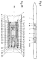
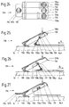
- FIG. 1 to 4 schematically show a ski 1, on the top 1a of which a toe 2 and a heel holder 3 are attached. Furthermore, a stiffening device 4 is attached to the ski 1, the rear portion 4b of which is attached with its end in the spring system 5 in the immediate vicinity of the heel holder 3.
- the front section 4a passes through the front jaw 2 and its end section engages with a ski-fixed control mechanism 6.
- each ski has a so-called camber height h o which is determined by the factory and is not shown separately in the drawing.
- 1 shows the ski 1 with the above-mentioned components in the inactive position of the control mechanism 6 with the curvature height h 1.
- the ineffective position is also referred to in the following as a neutral position or neutral position.
- FIG. 2 shows the ski 1 in a position in which the control mechanism 6 brings the ski under pressure to an increased curvature height h 2 compared to its neutral position.
- FIG. 3 relates to such a position of the control mechanism 6, which shows a decrease in the curvature height to h 3 compared to that of the neutral position with the curvature height h 1 corresponds.
- the ski can be adapted to the respective slope conditions in a manner desired by the user.
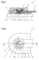
- the control mechanism 6 consists of a base body 7 which is fastened on the ski 1 by means of only indicated screws 8 and in which base body 7 the front section 4a of the stiffening device 4 is guided in a horizontally sliding manner.
- An eccentric body 9 has two parts which are offset in the vertical direction and concentric with respect to the central axis 18, namely an upper part 9a and a lower part 9b, between which the actual eccentric 9d is arranged.
- the eccentric body 9 is supported by means of the two mutually concentric parts 9a and 9b in the base body 7 and engages with its eccentric 9d in an elongated recess 4c of the front section 4a of the stiffening device 4.
- a handwheel 10 Arranged on the base body 7 is a handwheel 10 which is independent of this and which, by means of a coupling pin 10a fastened thereon, engaging in an elongated recess 9c of the upper part 9a of the eccentric body 9 produces a positive connection between the eccentric body 9 and the handwheel 10.
- the eccentric 9d with its longitudinal axis is normal to the longitudinal axis of the stiffening device 4.
- the eccentric body 9 is rotated about its axis by the interaction of the coupling pin 10a and the elongated recess 9c.
- the eccentric 9d thereby sets the front section 4a of the stiffening device 4 to the left or right, depending on the direction of rotation. If the handwheel 10 is turned to the right, the stiffening device 4 also moves to the right, ie to the rear, as shown in FIGS. 7 and 8.
- the control mechanism 6 is in this position the ski 1 in the position shown in FIG. 2 and has the curvature height h 2 .
- the stiffening device 4 When the handwheel 10 is turned to the left, the stiffening device 4 according to FIGS. 9 and 10 moves into a position which is shifted to the left, ie to the front. In this position of the control mechanism 6, the ski 1 is in the position according to FIG. 3 and has the curvature height h 3 .
- the control mechanism 106 has an eccentric body 109 with a centering pin 114 passing through it.
- the eccentric body 109 is mounted in the base body 107 by means of the centering pin 114.
- a pivot bearing 112 is provided for a folding lever 113 pivotable about a transverse axis 112a.
- the folding lever 113 allows the eccentric body 109 to be rotated slightly about a vertical axis 118 of the centering pin 114 in two directions with respect to its neutral position, as a result of which the front section 4a of the stiffening device 4, with its oval recess 4c, is also positively connected to the eccentric 109d corresponding relative movements with respect to the base body 107 are carried out, as a result of which the curvature height of the ski can be adjusted bilaterally, as already described.
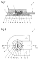
- an adjusting disk 215 is rotatably mounted by means of grip tabs 215a in a base body 207 which is independent of the ski 1 and is connected to it by means of only indicated screws 8 about the vertical axis 218 of the centering pin 214.
- the driver 216 and thereby also the stiffening device 4 perform movements in the direction of the longitudinal axis of the stiffening device 4 due to the design of the continuously increasing contour of the control groove 217 Connection between the front section 4a of the stiffening device 4 and the driver 216, the movements of the stiffening device 4 take place both in terms of size and in the direction according to those which were caused by the adjusting disk 215.
- a base body 307 on the upper side 1a of the ski, which is connected to the ski 1 by screws (not shown).
- the base body 307 has a front and a rear stop surface 321 and 322, respectively.
- a hand lever 320 is articulated on a horizontal transverse axis 319.
- a reversing lever 323 is articulated on the underside and in the central region thereof.
- a stop body 324 is articulated on the side of the reversing lever 323 facing away from the hand lever 320.
- the parts 319 to 324 thus form a kind of toggle mechanism.
- a folding lever 413 is pivotally mounted on the eccentric upper part 409a of the eccentric body 409 in a pivot bearing 412 on its transverse axis 412a.
- An intermediate piece 426 is provided with a first elongated hole 427, in which the eccentric 409d engages.
- the base body 407 is provided with a pivot pin 425, around which the intermediate piece 426 can perform pivoting movements.
- a driver 416 of the front section 4a of the stiffening device 4 is guided with play.
- the eccentric 409d describes an eccentric circular arc with its center.
- the intermediate piece 426 is entrained by the eccentric 409d which moves along the elongated hole 427 and thereby performs a rotary movement about the pivot pin 425.
- the driver 416 slides in the second elongated hole 428 and thereby displaces the stiffening device 4 in its axial direction.
- the distance between the driver 416 and the base body 407 is either increased or decreased, and the stiffening device 4 is put under pressure or tension, which brings about the bidirectional change in the curvature height on the ski (see FIGS. 2 and 3).
- a base body 507 is fastened on the upper side 1a of a ski 1 by means of screws 8 which are only indicated.
- the front section 4a of the stiffening device 4 is slidably mounted and has a firmly connected driver 516 on its end closest to the base body 507.
- the centering pin 514 which has the vertical axis 518, is mounted in the base body 507 and in turn serves to support the eccentric body 509.
- the intermediate piece 526 which is coupled to the eccentric 509, follows its movement and, after the clearance between the elongated hole 527 and the driver 516 has been bridged, displaces the front section 4a of the stiffening device 4 via the driver 516
- the distance between the base body 507 and the front section 4a of the stiffening device 4 is either increased or decreased, which brings about the bidirectional change in the curvature height of the ski.
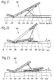
- an axis 630 mounted on the ski 1 in a bearing (not shown) is arranged on the upper side 1a of the ski 1.
- a neutral lever 631, a pull lever 632 and a pressure lever 633 are pivotably attached to this axis 630.
- a tension connection lever 634 is rotatably mounted on the tension lever 632, which on the other hand connects to the front section 4a of the stiffening device 4 is pivotally connected by means of a draw bolt 636.
- a pressure connection lever 635 is articulated on the pressure lever 633, which is also connected at its end facing away from the pressure lever 633 by means of a pressure bolt 637 to the front section 4a of the stiffening device 4 so that it can rotate. If the pull lever 632 or the push lever 633 is in the active position, the neutral lever 631 serves to move the other lever 633 or 632 to the neutral position before the other lever 633 or 632 is actuated, in order to prevent the pull lever 632 and push lever 633 from simultaneously the effective situation will be brought. After a previous actuation of the neutral lever 631, the pressure lever 633 was now pressed downward according to FIG.
- the pressure connection lever 635 thereby comes into an approximately horizontal position, whereby the front section 4a of the stiffening device 4 is subjected to pressure via the pressure pin 637, see arrow P 2 , and the curvature height of the ski, corresponding to FIG. 2 , is increased to h 2 . If the curvature height is now to be reduced, the neutral lever 631 is first actuated, as a result of which the pressure lever 633 becomes ineffective and the front section 4a of the stiffening device is de-energized.
- the pull connecting lever 634 comes into an approximately horizontal position and, by moving the pull bolt 636 in the direction of arrow P 1, causes a tensile stress on the front section 4a of the stiffening device 4, thereby increasing the curvature of the ski according to FIG. 3 to h 3 is reduced.
- the eighth variant of the control mechanism 706 according to FIGS. 24 to 27 is a further development of the previous seventh variant.
- the transverse axis 730 is mounted in a bearing, not shown, on which the neutral lever 731 with an associated opening spring 731a, the tension lever 732 with an associated opening spring 732a and the pressure lever 733 with an associated opening spring 733a are pivotably arranged .
- the front section 4a of the stiffening device 4 as shown in FIGS A draw bolt 736 and a pressure bolt 737 are attached substantially at right angles to the longitudinal axis of the stiffening device 4.
- a tension connection lever 734 is articulated on the tension bolt 736, a cross bolt 734a engaging in its upper end section in a hook-shaped recess 739 of the tension lever 732 provided with hooks 739a and in a longitudinal groove 740 of the neutral lever 731 (see Figures 24 and 27), and one Leg spring 734b causes the tension connecting lever 734 to bear against the hook-shaped recess 739 of the tension lever 732.
- a pressure connection lever 735 is connected in an articulated manner to the pressure pin 737. This engages with its transverse bolt 735a into a hook-shaped recess 739 'of the pressure lever 733 provided with a hook 739'a and into the longitudinal groove 740, as shown in FIGS.
- a leg spring 735b causes the pressure connection lever 735 to rest against the hook-shaped recess 739 'of the pressure lever 733.
- the tension lever 732 and the pressure lever 733 each have a recess 732b, 733b
- the neutral lever 731 has two recesses 731b, 731'b provided, in order to offer a better grip when operating with a ski pole.
- the second recess 731'b of the neutral lever 731 is formed on an extension 731c.
- the pressure lever 733 and neutral lever 731 also come to rest horizontally without having any effect.
- the hook 739'a of the hook-shaped recess 739 'of the pressure lever 733 comes into engagement with the cross bolt 735a of the pressure connection lever 735.
- the front section 4a of the stiffening device 4 moves in the direction indicated by the arrow P 2 in FIG. 26.
- Pull lever 732 and neutral lever 731 also assume a horizontal position due to the coupling with the longitudinal groove 740 of the neutral lever 731.
- the invention also relates to the special configuration of a spring system which is to be protected by the characterizing features of claim 17. Due to the measures contained in this claim, a power transmission for changing the springs provided in the spring system is manually and continuously set via the control mechanism and also changed in its direction of action. Further advantageous configurations of this spring system result from claims 18 to 23 and from the description which now follows.
- the coil springs used were also referred to as springs for the sake of simplicity and general designation.
- the stop plates 842, 843, 844 and the end part 845 are guided on guide surfaces 841a, 841b, 841c and 841d of the bearing body 841.
- the front stop plate 842 has a pin 842a. Symmetrical to the longitudinal axis of the stiffening device 4 are formed in the same threaded bores 846a, 846b, which are used to receive one screw 847a, 847b.
- the screws 847a, 847b each serve to guide a spring 848a, 848b arranged between the front stop plate 842 and the middle stop plate 843.
- the shafts of the screws 847a and 847b slide in bores in the front, middle and rear stop plates 842, 843 and 844, and in the end part 845.
- the screws 847a, 847b are slidably supported in the end part 845 by means of their heads 847c, 847d.
- a through hole 845a is also formed in the end part 845, through which a threaded bolt 849 is screwed into a through thread of the rear stop plate 844.
- a forward-facing pin 849a is formed on the threaded bolt 849.
- the pin 842a of the front stop plate 842 and the pin 849a of the threaded bolt 849 serve to center another coil spring 848c.
- the bolts 847a, 847b are also moved to the left by their anchoring in the threaded bores 846a, 846b and act on the end part 845 via their heads 847c, 847d and subsequently also take the rear stop plate 844 with them.
- the middle stop plate 843 is also displaced via the threaded bolt 849 screwed to the rear stop plate 844.
- a further embodiment according to the invention is characterized in that the control mechanism is equipped with a device for displaying the degree of stiffening or the bulge height of the gliding device, with either a mark on the base body and markings on the rotatable component or on the handle, preferably with dimensions, being provided .
- the arrangement of the mark can also be interchanged with that of the markings.
Landscapes
- Footwear And Its Accessory, Manufacturing Method And Apparatuses (AREA)
- Vehicle Body Suspensions (AREA)
- Springs (AREA)
Abstract
Description
Die Erfindung betrifft eine Vorrichtung zum Verändern der Härte, Elastizität oder Steifigkeit eines Gleitgerätes für den Schnee, insbesondere eines Alpinski oder Snowboards, welches Gleitgerät eine vom Werk her vorbestimmte Wölbungshöhe aufweist, mit einer am Gleitgerät anbringbaren Versteifungsvorrichtung, die in ihrer Wirkung auf das Gleitgerät durch einen Steuerungsmechanismus veränderbar ist.The invention relates to a device for changing the hardness, elasticity or rigidity of a gliding device for snow, in particular an alpine ski or snowboard, which gliding device has a curvature height predetermined by the factory, with a stiffening device which can be attached to the gliding device and which acts on the gliding device a control mechanism is changeable.
Eine solche Vorrichtung ist in der DE-PS 12 98 024 geoffenbart, gemäß welcher ein nockenbetätigtes Verstellsystem, welches die Härte des Ski über Schubstangen zu verändern gestattet. Die Schubstangen sind unterhalb der Skioberseite angebracht und die Einstellung der Schubstangen erfolgt mittels Nocken oder Gewindespindeln. Auf Grund der diskontinuierlichen Nockenkrümmung ist bei Betätigung des Verstellsystemes die Einstellkraft größer als die Fixierkraft, wodurch ein zusätzlicher Kraftaufwand erforderlich ist. Weiters ist eine Anordnung dieser bekannten Vorrichtung im Skikörper umständlich und ausschließlich vom Werk her durchführbar.Such a device is disclosed in DE-PS 12 98 024, according to which a cam-operated adjustment system, which allows the hardness of the ski to be changed via push rods. The push rods are located below the top of the ski and the push rods are adjusted using cams or threaded spindles. Due to the discontinuous cam curvature, the setting force is greater than the fixing force when the adjustment system is actuated, which means that additional force is required. Furthermore, an arrangement of this known device in the ski body is cumbersome and can only be carried out at the factory.
Die FR-PS-1,118.857 beschreibt eine Versteifungseinrichtung mit einem auf der Skioberseite liegenden Druckstab, wobei die Verstellspindel teilweise über/unter die Skioberseite gelegt dargestellt wird. Die Ausführung des Druckstabes als Zahnstangenelement bedingt, ebenso wie die versenkte Ausführung sowie die Anlenkung der Zahnstangen, einen nicht unerheblichen Fertigungsaufwand. In der FR-PS-1.109.560 ist ein Steuerungsmechanismus geoffenbart, bei welchem die Versteifung über zwei miteinander gekoppelte Kniehebelsysteme erfolgt.FR-PS-1,118,857 describes a stiffening device with a pressure rod lying on the upper side of the ski, the adjusting spindle being shown partially above / below the upper side of the ski. The design of the pressure rod as a rack element, as well as the recessed design and the articulation of the toothed racks, require a considerable amount of work. A control mechanism is disclosed in FR-PS-1.109.560, in which the stiffening takes place via two toggle lever systems coupled to one another.
In der US-PS-4,221.400 sind vorgekrümmte Stäbe beschrieben. Diese werden in zylindrische Bohrungen, welche im Ski in Richtung der Längsachse verlaufen, eingebracht. Mittels Rotation dieser Stäbe wird eine Änderung der Krümmung, Härte sowie Steifigkeit des Ski bewirkt. Die gleichzeitige Betätigung mehrerer Stäbe ist als aufwendig zu bezeichnen, wobei noch hinzukommt, daß der Kraftaufwand beträchtlich ist.Pre-curved rods are described in U.S. Patent 4,221,400. These are made in cylindrical bores that run in the ski in the direction of the longitudinal axis. Rotation of these rods changes the curvature, hardness and stiffness of the ski. The simultaneous actuation Several bars can be described as complex, with the fact that the effort is considerable.
In der US-PS-4,300.786 sind auswechselbare, an den Seiten des Ski angebrachte Versteifungsstäbe genannt, welche die Flexibilität des Ski im jeweils gewünschten Sinne beeinflussen. Allein das Auswechseln der Stäbe kann als problematisch angesehen werden, ist doch für die verschiedenen Pistenverhältnisse eine Vielzahl von Versteifungsstäben mitzuführen.US Pat. No. 4,300,786 mentions interchangeable stiffening bars attached to the sides of the ski, which influence the flexibility of the ski in the desired sense. Replacing the bars alone can be viewed as problematic, since a large number of stiffening bars must be carried for the different slope conditions.
Die DE-OS-33 15 638 beschreibt eine Versteifungsvorrichtung mit einem im wesentlichen parallel zur Skioberseite verlaufenden Zugband, wobei die Versteifungskräfte über vertikal angeordnete Verstelleinrichtungen vom Zugband in den Ski eingeleitet werden.DE-OS-33 15 638 describes a stiffening device with a tension band running essentially parallel to the upper side of the ski, the stiffening forces being introduced from the tension band into the ski via vertically arranged adjustment devices.
In der FR-OS-2,448.360 ist ein hiezu ähnliches System angegeben. Hier ist im vorderen Bereich des Ski eine in vertikaler Richtung erhöhte Versteifungsvorrichtung vorgesehen, welche fahrtechnische Risiken sowie Verschmutzungsprobleme der Versteifungsvorrichtung mit sich bringen kann.A similar system is specified in FR-OS-2,448,360. Here, in the front area of the ski, a stiffening device is provided which is raised in the vertical direction and which can result in technical driving risks and contamination problems of the stiffening device.
In der US-PS-2,258.046 wird ein geteiltes Versteifungsband durch einen horizontal gelagerten Kreisexzenter betätigt. Die Betätigung erfolgt über einen Hebel mittels eines Schuhes. Diese Ausführung bietet einigermaßen Schutz gegen Schneezutritt, wohingegen die Krafteinleitung in den Ski zweier zusätzlicher plattenförmiger Teile bedarf.In US-PS-2,258,046 a divided stiffening band is actuated by a horizontally mounted circular eccentric. It is operated via a lever using a shoe. This version offers some protection against snow, whereas the force transfer into the ski requires two additional plate-shaped parts.
Eine weiters bekannte technische Lösung ist in der FR-PS-2,689.411 angegeben, bei welcher ein in seiner Mitte geteilter, mit der Skioberseite elastisch oder starr verbundener zweiteiliger Versteifungskörper vorgesehen ist. Dabei wird zur Veränderung der Härte und Steifigkeit des Ski die Art der Ausbildung eines Trennspaltes zwischen den hinteren und vorderen benützt. Durch Einsetzen von elastischen Elementen in den Spalt wird eine gestufte Biegecharakteristik in einer Richtung erreicht, jedoch eine willkürliche Veränderung der Steifigkeit des Ski durch den Benutzer nicht ermöglicht.A further known technical solution is given in FR-PS-2,689,411, in which a two-part stiffening body is provided which is divided in the middle and is connected elastically or rigidly to the upper side of the ski. To change the hardness and rigidity of the ski, the type of separation gap between the rear and front is used. By inserting elastic elements in the gap, a stepped bending characteristic in one direction is achieved, but an arbitrary change in the rigidity of the ski is not made possible by the user.
Die FR-PS-2,690.078 versteift den Ski dynamisch in einer Richtung während der Fahrt mittels eines Kniehebels sowie dem vom Hinterteil des Skischuhes ausgeübten Fersendruck, welcher auf die Versteifungseinrichtung wirkt. Das DE-GM-91 16 875.9 beschreibt eine Tragplattenanordnung, bei welcher die Tragplatte durch eine Nockenscheibe oder ein Fliehgewicht versteift wird. In der WO94/08669 wird ein Versteifunggsstab geoffenbart, welcher gegen die Skioberseite erhöht angebracht
ist und kontinuierliche Verstellung über eine Gewindeverstellscheibe beschreibt.The FR-PS-2,690,078 stiffens the ski dynamically in one direction while driving by means of a knee lever and the heel pressure exerted by the rear of the ski boot, which acts on the stiffening device. DE-GM-91 16 875.9 describes a support plate arrangement in which the support plate is stiffened by a cam or a flyweight. A stiffening rod is disclosed in WO94 / 08669, which is mounted higher against the top of the ski
is and describes continuous adjustment via a thread adjustment disc.
In der FR-PS-2,649.902 ist eine gegenüber der Skioberseite erhöht angebrachte, in Richtung der Achse des Ski elastisch gelagerte sowie versteifbare Tragplatte für eine vollständige Sicherheitsbindung geoffenbart.FR-PS-2,649.902 discloses a support plate which is mounted higher than the top of the ski and is elastically mounted and stiffenable in the direction of the axis of the ski for a complete safety bond.
Bei der Mehrzahl der oben angeführten Lösungen werden für die Verstellung zusätzliche Utensilien (Hebel oder ähnliche Kleinwerkzeuge) benötigt, deren Mitführung bei der Fahrt sowohl hinderlich ist als auch vom sicherheitstechnischen Standpunkt aus bedenklich erscheint. Bei gewissen Ausführungen besteht zudem noch die Möglichkeit der Vereisung, wodurch die Verstellmöglichkeiten in deren eigentlicher Funktion eingeschränkt werden. Die Veränderung der Wölbungshöhe ist ebenfalls nicht bei allen Lösungen in ausreichendem Maße möglich.In the majority of the solutions listed above, additional utensils (levers or similar small tools) are required for the adjustment, the carrying of which is both a hindrance when driving and also appears to be of concern from a safety point of view. With certain versions there is also the possibility of icing, which limits the adjustment options in their actual function. It is also not possible to change the curvature height to a sufficient extent with all solutions.
Die Erfindung hat sich die Aufgabe gestellt, eine Vorrichtung zur Veränderung der Wölbungshöhe und damit der Härte, Elastizität oder Steifigkeit eines Gleitgerätes der eingangs genannten Art vornehmen zu können. Dabei sollen zufolge der Veränderung der Wölbungshöhe die Fahreigenschaften den Pistengegebenheiten dem Stand der Technik gegenüber in erhöhtem Maße angepaßt werden können.The invention has for its object to be able to make a device for changing the curvature height and thus the hardness, elasticity or rigidity of a gliding device of the type mentioned. According to the change in the curvature height, the driving properties should be able to be adapted to the state of the art to a greater extent than the slope conditions.
Gelöst wird die gestellte Aufgabe durch die im Anspruch 1 angeführten kennzeichnenden Merkmale. Die erfindungsgemäße Ausgestaltung ermöglicht nicht nur eine manuelle Betätigung des Steuerungsmechanismus, sondern durch dessen Ausgestaltung auch ein kontinuierliches Verstellen der Wöhlbungshöhe und somit der Härte, Elastizität oder Steifigkeit des Gleitgerätes.The problem is solved by the characterizing features stated in
Durch die Merkmale des Anspruches 2 wird außerdem eine bidirektionale Betätigung, Erhöhung bzw. Minderung der Wölbungshöhe ermöglicht. Weitere vorteilhafte und erfindungsgemäße Ausgestaltungen ergeben sich aus den Ansprüchen 3 bis 16, 24 und 25.The features of
Die Erfindung wird nun anhand der Zeichnung in Verbindung mit mehreren Ausführungsbeispielen näher beschrieben. Hiebei zeigen : Die Figuren 1 bis 4 einen Ski mit einer Versteifungsvorrichtung, wobei die Fig.1 den Ski in Seitenansicht mit einer Wölbungshöhe entsprechend einem unbetätigten Steuerungsmechanismus zeigt, die Figuren 2 und 3 den Ski durch Betätigung des Steuerungsmechanismus in zwei voneinander unterschiedliche Stellungen gebracht zeigen, und Fig. 4 die Draufsicht von Fig.1 ist. Die Figuren 5 bis 10 zeigen ein erstes Ausführungsbeispiel eines Steuerungsmechanismus, wobei Fig. 5 einen Längsschnitt nach der Linie V-V der Fig. 6 durch den Steuerungsmechanismus in der neutralen Lage, Fig. 6 eine Draufsicht von Fig. 5 jedoch ohne Handrad, Fig. 7 einen Schnitt nach der Linie VII-VII in der Fig. 8 in einer Stellung des Steuerungsmechanismus entsprechend der Lage des Ski nach Fig. 2, die Fig. 8 eine Draufsicht zu Fig.7, wobei das Handrad weggelassen wurde, die Fig.9 einen Längsschnitt entlang der Linie IX-IX der Fig. 10 in einer Stellung des Steuerungsmechanismus entsprechend der Lage des Ski gemäß Fig. 3 und die Fig. 10 eine Draufsicht von Fig. 9 ohne Handrad zeigen. Die Figuren 11 bis 14 stellen zwei weitere Ausführungsbeispiele von Steuerungsmechanismen dar, wobei die Fig. 11 einen Längsschnitt nach der Linie XI-XI der Fig. 12 und Fig. 12 einen Schnitt nach der Linie XII-XII der Fig. 11 einer zweiten Variante des Steuermechanismus, die Fig. 13 einen Längsschnitt entlang der Linie XIII-XIII der Fig. 14 und Fig. 14 die Draufsicht auf die Fig. 13 einer dritten Variante des Steuerungsmechanismus zeigt bzw. zeigen. Die Figuren 15 und 16 zeigen - in schematischer Darstellung - die vierte Variante eines Steuerungsmechanismus. Die Figuren 17 und 18 zeigen Vorderansicht und Draufsicht eines fünften Ausführungsbeispiels des Steuerungsmechanismus, wobei Fig.17 einen Schnitt entlang der Linie XVII-XVII der Fig.18 und Fig.18 einen Schnitt nach der Linie XVIII-XVIII der Fig.17 darstellen. Die Figuren 19 und 20 zeigen Vorderansicht und Draufsicht einer sechsten Variante eines Steuerungsmechanismus, wobei Fig.19 einen Längsschnitt entlang der Linie XIX-XIX der Fig.20 und Fig.20 einen Schnitt entlang der Linie XX-XX der Fig.19 zeigt. Die Figuren 21, 22 und 23 stellen - wiederum in schematischer Darstellung - eine siebente Variante des Steuerungsmechanismus dar. Die Figuren 24 bis 27 zeigen als achte Ausführungsform eine Abwandlung der siebenten Variante eines Steuerungsmechanismus. Die Figur 28 zeigt eine Ausführungsform eines Federsystemens in teilweise geschnittener Draufsicht.The invention will now be described in more detail with reference to the drawing in connection with several exemplary embodiments. 1 to 4 show a ski with a stiffening device, FIG. 1 showing the ski in side view with a bulge height corresponding to an unactuated control mechanism, FIGS. 2 and 3 show the ski brought into two different positions by actuating the control mechanism , and Figure 4 is the top view of Figure 1. FIGS. 5 to 10 show a first exemplary embodiment of a control mechanism, FIG. 5 a longitudinal section along the line VV of FIG. 6 through the control mechanism in the neutral position, FIG. 6 a top view of FIG. 5 but without a handwheel, FIG. 7 a section along the line VII-VII in FIG. 8 in a position of the control mechanism corresponding to the position of the ski according to FIG. 2, FIG. 8 is a plan view of FIG. 7, the handwheel being omitted, FIG 10 in a position of the control mechanism corresponding to the position of the ski according to FIG. 3 and FIG. 10 show a plan view of FIG. 9 without a handwheel. FIGS. 11 to 14 represent two further exemplary embodiments of control mechanisms, with FIG. 11 a longitudinal section along the line XI-XI of FIG. 12 and FIG. 12 a section along the line XII-XII of FIG. 11 of a second variant of the Control mechanism, the Fig. 13 shows a longitudinal section along the line XIII-XIII of Fig. 14 and Fig. 14 shows the plan view of Fig. 13 of a third variant of the control mechanism. Figures 15 and 16 show - in a schematic representation - the fourth variant of a control mechanism. FIGS. 17 and 18 show a front view and a top view of a fifth exemplary embodiment of the control mechanism, FIG. 17 showing a section along the line XVII-XVII in FIG. 18 and FIG. 18 a section along the line XVIII-XVIII in FIG. FIGS. 19 and 20 show a front view and a top view of a sixth variant of a control mechanism, FIG. 19 showing a longitudinal section along the line XIX-XIX of FIG. 20 and FIG. 20 a section along the line XX-XX of FIG. 19. FIGS. 21, 22 and 23 represent - again in a schematic representation - a seventh variant of the control mechanism. FIGS. 24 to 27 show an eighth embodiment of a modification of the seventh variant of a control mechanism. FIG. 28 shows an embodiment of a spring system in a partially sectioned top view.
In den Figuren 1 bis 4 ist schematisch ein Ski 1 dargestellt, auf dessen Oberseite 1a ein Vorderbacken 2 und ein Fersenhalter 3 befestigt sind. Weiters ist auf dem Ski 1 eine Versteifungsvorrichtung 4 angebracht, deren hinterer Abschnitt 4b mit ihrem Ende im Federsystem 5 in der unmittelbaren Nähe des Fersenhalters 3, angebracht ist. Der vordere Abschnitt 4a durchsetzt den Vorderbacken 2 und steht mit seinem Endabschnitt mit einem skifesten Steuerungsmechanismus 6 in Eingriff.1 to 4 schematically show a
In bekannter Weise hat jeder Ski eine vom Werk her bestimmte, in der Zeichnung gesondert nicht dargestellte, sogenannte Wölbungshöhe h o . Die Fig. 1 stellt den Ski 1 mit den darauf befindlichen, vorangehend angeführten Bauteilen in der unwirksamen Stellung des Steuerungsmechanismus 6 mit der Wölbungshöhe h 1 dar. Die unwirksame Lage wird in der weiteren Folge fallweise auch als neutrale Lage, oder Neutralstellung bezeichnet. Fig. 2 zeigt den Ski 1 in einer Lage, bei welcher der Steuerungsmechanismus 6 gegenüber seiner neutrale Lage den Ski unter Druck in eine erhöhte Wölbungshöhe h 2 bringt. Die Fig. 3 bezieht sich auf eine derartige Stellung des Steuerungsmechanismus 6, welche einer Abnahme der Wölbungshöhe auf h 3 gegenüber derjenigen der neutralen Lage mit der Wölbungshöhe h 1 entspricht. Mit der in den Figuren 2 und 3 gezeigten "bidirektionalen" Verstellmöglichkeit der Wölbungshöhe kann die Anpassung des Ski an die jeweiligen Pistenverhältnisse in einer vom Benutzer gewünschten Weise erfolgen.In a known manner, each ski has a so-called camber height h o which is determined by the factory and is not shown separately in the drawing. 1 shows the
Der Steuerungsmechanismus 6 besteht gemäß den Figuren 5 bis 10 aus einem Grundkörper 7, welcher auf dem Ski 1 mittels nur angedeuteter Schrauben 8 befestigt und in welchem Grundkörper 7 die Versteifungsvorrichtung 4 mit ihrem vorderen Abschnitt 4a horizontal gleitend geführt ist. Ein Exzenterkörper 9 weist zwei in Höhenrichtung zueinander versetzt angeordnete, bezüglich der Mittelachse 18 konzentrische Teile, nämlich einen Oberteil 9a und einen Unterteil 9b auf, zwischen welchen der eigentliche Exzenter 9d angeordnet ist. Der Exzenterkörper 9 ist mittels der beiden zueinander konzentrischen Teile 9a und 9b im Grundkörper 7 gelagert und greift mit seinem Exzenter 9d in eine längliche Ausnehmung 4c des vorderen Abschnittes 4a der Versteifungsvorrichtung 4 ein. Auf dem Grundkörper 7 ist ein von diesem unabhängiges Handrad 10 angeordnet, welches mit einem an diesem befestigten Kupplungszapfen 10a in eine längliche Ausnehmung 9c des Oberteiles 9a des Exzenterkörpers 9 eingreifend eine formschlüssige Verbindung zwischen dem Exzenterkörper 9 und dem Handrad 10 bewirkt.According to FIGS. 5 to 10, the
In der neutralen Lage des Steuerungsmechanismus 6 nach den Figuren 5 und 6 steht der Exzenter 9d mit seiner Längsachse normal zur Längsachse der Versteifungsvorrichtung 4. Durch Verdrehen des Handrades 10 wird der Exzenterkörper 9 durch Zusammenwirken von Kupplungszapfen 10a und länglicher Ausnehmung 9c um seine Achse gedreht. Der Exzenter 9d versetzt dadurch den vorderen Abschnitt 4a der Versteifungsvorrichtung 4, je nach Drehrichtung, nach links oder rechts in Bewegung. Wird das Handrad 10 nach rechts verdreht, so bewegt sich, wie die Figuren 7 und 8 zeigen, die Versteifungsvorrichtung 4 ebenfalls nach rechts, d.h. nach hinten. In dieser Stellung des Steuerungsmechanismus 6 befindet sich der Ski 1 in der Lage nach der Fig. 2 und hat die Wölbungshöhe h 2 .In the neutral position of the
Beim Verdrehen des Handrades 10 nach links gerät die Versteifungsvorrichtung 4 gemäß den Figuren 9 und 10 in eine nach links, d.h. nach vorne, verschobene Lage. In dieser Stellung des Steuerungsmechanismus 6 befindet sich der Ski 1 in der Lage nach der Fig. 3 und hat die Wölbungshöhe h 3 .When the
Nach den Figuren 11 und 12 der zweiten Ausführungsform des Steuerungsmechanismus 106 ist dessen Grundkörper 107 ebenfalls mittels nur angedeuteter Schrauben 8 mit dem Ski 1 fix verbunden. In dieser Ausführungsform weist der Steuerungsmechanismus 106 einen Exzenterkörper 109 mit einem diesen durchsetzenden Zentrierbolzen 114 auf. Im vorderen Abschnitt 4a der Versteifungsvorrichtung 4 befindet sich eine ovale Ausnehmung 4c, in welche der Exzenter 109d eingreift. Der Exzenterkörper 109 ist mittels des Zentrierbolzens 114 im Grundkörper 107 gelagert. Am Oberteil 109a des Exzenterkörpers 109 ist ein Schwenklager 112 für einen um eine Querachse 112a schwenkbaren Klapphebel 113 vorgesehen. Im ausgeklappten Zustand ermöglicht der Klapphebel 113 ein leichtes Verdrehen des Exzenterkörpers 109 um eine vertikale Ache 118 des Zentrierbolzens 114 in zwei Richtungen gegenüber seiner Neutralstellung, wodurch der vordere Abschnitt 4a der Versteifungsvorrichtung 4, mit seiner ovalen Ausnehmung 4c mit dem Exzenter 109d formschlüssig verbunden, gleichfalls entsprechende Relativbewegungen gegenüber dem Grundkörper 107 vollführt, wodurch die Wölbungshöhe des Ski, wie bereits beschrieben, bilateral einstellbar ist.According to FIGS. 11 and 12 of the second embodiment of the
Im dritten Ausführungsbeispiel des Steuerungsmechanismus 206 nach den Figuren 13 und 14 ist in einem vom Ski 1 unabhängigen, mit diesem mittels nur angedeuteter Schrauben 8 verbundenen Grundkörper 207 um die vertikale Achse 218 des Zentrierbolzens 214 eine Verstellscheibe 215 mittels Grifflappen 215a drehbar gelagert. In dieser Verstellscheibe 215 ist eine stetig ansteigend verlaufende Steuernut 217 ausgebildet. Ein erhöht auf dem vorderen Abschnitt 4a der Versteifungsvorrichtung 4 angebrachter Mitnehmer 216 greift in die Steuernut 217 mit Spiel ein. Wird nun die Verstellscheibe 215 mittels der Grifflappen 215a um den Zentrierbolzen 214 verdreht, so vollführt der Mitnehmer 216 und dadurch auch die Versteifungsvorrichtung 4 eine auf Grund der Ausgestaltung der stetig ansteigenden Kontur der Steuernut 217 Bewegungen in Richtung der Längsachse der Versteifungsvorrichtung 4. Zufolge der starren Verbindung zwischen dem vorderen Abschnitt 4a der Versteifungseinrichtung 4 und dem Mitnehmer 216 erfolgen die Bewegungen der Versteifungseinrichtung 4 sowohl der Größe wie auch der Richtung nach denjenigen entsprechend, welche von der Verstellscheibe 215 hervorgerufen wurden.In the third exemplary embodiment of the
In der vierten Ausführungsform des Steuerungsmechanismus 306 nach den Figuren 15 und 16 befindet sich auf der Skioberseite 1a wiederum ein Grundkörper 307, welcher mit dem Ski 1 durch nicht dargstellte Schrauben verbunden ist. Der Grundkörper 307 weist eine vordere und eine hintere Anschlagfläche 321 bzw. 322 auf. Am vorderen Abschnitt 4a der Versteifungsvorrichtung 4 ist an einer horizontalen Querachse 319 ein Handhebel 320 angelenkt. An der Unterseite und im mittleren Bereich desselben ist ein Umsteuerhebel 323 gelenkig gelagert. An der vom Handhebel 320 abgewandten Seite des Umsteuerhebel 323 ist ein Anschlagkörper 324 gelenkig gelagert. Somit bilden die Teile 319 bis 324 eine Art Kniehebelmechanismus. Je nachdem, ob bei geöffnetem Handhebel 320 durch Schwenken des Umsteuerhebels 323 der Anschlagkörper 324 in die Richtung der vorderen Anschlagfläche 321 oder der hinteren Anschlagfläche 322 geklappt wird, erfolgt beim Hinunterdrücken des Handhebels 320 durch das Spannen des Kniehebelmechanismus, d.h. der Teile 319 bis 324 entweder eine Bewegung des vorderen Abschnittes 4a der Versteifungsvorrichtung 4 zum Grundkörper 307 s.Pfeil P 1 hin oder in die entgegengesetzte Richtung s.Pfeil P 2 , womit die bidirektionale Einstellung der Wölbungshöhe h 2 bzw. h 3 des Ski nach den Figuren 2 und 3 ermöglicht wird. Wird der Handhebel 320 nicht betätigt, so verbleibt, unabhängig von der Lage des Anschlagkörpers 324 der Steuerungsmechanismus 306, wie in den Figuren 15 und 16 dargestellt ist, in der Neutralstellung. Im Anschlagkörper kann ein Innengewinde mit einem darin befindlichen Schraubenbolzen angebracht werden. Je nachdem, wie weit der Schraubenbolzen aus dem Anschlagkörper gegen die jeweilige Anschlagfläche hervorragt, wird damit die Größe der Verschiebung der Versteifungsvorrichtung 4 verändert.In the fourth embodiment of the
In der fünften Ausführungsform des Steuerungsmechanismus 406 nach den Figuren 17 und 18 ist auf dem Exzenteroberteil 409a des Exzenterkörpers 409 in einem Schwenklager 412 an dessen Querachse 412a ein Klapphebel 413 schwenkbar gelagert. Ein Zwischenstück 426 ist mit einem ersten Langloch 427 versehen, in welches der Exzenter 409d eingreift. Der Grundkörper 407 ist mit einem Schwenkbolzen 425 versehen, um welchen das Zwischenstück 426 Schwenkbewegungen ausführen kann. In einem zweiten Langloch 428 des Zwischenstückes 426 wird ein Mitnehmer 416 des vorderen Abschnittes 4a der Versteifungsvorrichtung 4 mit Spiel geführt. Wird nun durch Verdrehen des ausgeklappten Klapphebels 413 der Exzenterkörper 409 um die vertikale Achse 418 des Zentrierbolzens 414 gedreht, so beschreibt der Exzenter 409d mit seinem Mittelpunkt einen exzentrischen Kreisbogen. Das Zwischenstück 426 wird vom Exzenter 409d welcher sich entlang des Langloches 427 bewegt mitgenommen und vollführt dadurch eine Drehbewegung um den Schwenkbolzen 425. Dabei gleitet der Mitnehmer 416 im zweiten Langloch 428 und verschiebt dadurch die Versteifungsvorrichtung 4 in deren Achsrichtung. Der Drehrichtung des Klapphebels 412 entsprechend wird die Distanz zwischen dem Mitnehmer 416 und dem Grundkörper 407 entweder vergrößert oder verringert, sowie die Versteifungsvorrichtung 4 unter Druck bzw. Zug gesetzt, wodurch die bidirektionale Veränderung der Wölbungshöhe am Ski herbeigeführt wird (vgl. Fig. 2 und 3).In the fifth embodiment of the
Bei der sechsten Ausführungsform des Steuerungsmechanismus 506 nach den Figuren 19 und 20 ist ein Grundkörper 507 mittels nur angedeuteter Schrauben 8 auf der Oberseite 1a eines Ski 1 befestigt. Desgleichen ist auf der Skioberseite 1a gleitend der vordere Abschnitt 4a der Versteifungsvorrichtung 4 angebracht, welcher auf seinem dem Grundkörper 507 nächstgelegenen Ende einen fest verbundenen Mitnehmer 516 aufweist. Im Grundkörper 507 ist der die vertikale Achse 518 aufweisende Zentrierbolzen 514 gelagert, welcher wiederum zur Lagerung des Exzenterkörpers 509 dient. An dem Oberteil 509a des Exzenterkörpers 509 befindet sich, mit diesem fix verbunden, zumindest ein Griffstück 529. Dieses Griffstück 529 ermöglicht eine leichte Bedienung des Steuerungsmechanismus 506. Exzentrisch zur vertikalen Achse 518 des Zentrierbolzens 514, um welche sich der Exzenterkörper 509 bei Betätigung des Griffstückes 529 dreht, ist der Exzenter 509d angeordnet. Gemäß Fig. 19 ist das Zwischenstück 526 mit dem Exzenter 509d gekoppelt. Weiters greift der im vorderem Abschnitt 4a gelagerter Mitnehmer 516 mit Spiel in ein Langloch 527 des Zwischenstücks 526 ein. Durch Verdrehen mittels des Griffstückes 529 wird der Exzenterkörper 509 um die vertikale Achse 518 gedreht, wodurch der Mittelpunkt des Exzenters 509d eine exzentrische Kreisbewegung vollführt. Das Zwischenstück 526, welches mit dem Exzenter 509 gekoppelt ist, folgt dessen Bewegung und verschiebt, nachdem das Spiel zwischen dem Langloch 527 und dem Mitnehmer 516 überbrückt wurde, über den Mitnehmer 516 den vorderen Abschnitt 4a der Versteifungsvorrichtung 4. Entsprechend der gewählten Drehrichtung wird der Abstand zwischen dem Grundkörper 507 sowie dem vorderen Abschnitt 4a der Versteifungsvorrichtung 4 entweder vergrößert oder verringert, wodurch die bidirektionale Veränderung der Wölbungshöhe des Ski herbeigeführt wird.In the sixth embodiment of the
In der siebenten Variante eines Steuerungsmechanismus 606 nach den Figuren 21,22 und 23 ist auf der Oberseite 1a des Ski 1 eine auf dem Ski 1 in einem nicht dargestellten Lager gelagerte Achse 630 angeordnet. An dieser Achse 630 sind ein Neutralhebel 631, ein Zughebel 632 sowie ein Druckhebel 633 schwenkbar befestigt. Am Zughebel 632 ist ein Zugverbindungshebel 634 drehbar gelagert, welcher andererseits mit dem vorderen Abschnitt 4a der Versteifungsvorrichtung 4 mittels eines Zugbolzens 636 drehgelenkig verbunden ist. Am Druckhebel 633 ist ein Druckverbindungshebel 635 angelenkt, welcher an seinem vom Druckhebel 633 abgewandten Ende mittels eines Druckbolzens 637 mit dem vorderen Abschnitt 4a der Versteifungsvorrichtung 4 gleichfalls drehbeweglich verbunden ist. Befindet sich der Zughebel 632 oder der Druckhebel 633 in der wirksamen Lage, so dient der Neutralhebel 631 dazu, vor dem Betätigen des anderen Hebels 633 bzw. 632 diesen in die Neutralstellung zu versetzen, um zu verhindern, daß Zughebel 632 und Druckhebel 633 gleichzeitig in die wirksame Lage gebracht werden. Nach einer vorausgehenden Betätigung des Neutralhebels 631 wurde nach der Fig.22 nunmehr der Druckhebel 633 nach unten gedrückt. Der Druckverbindungshebel 635 kommt dadurch in eine etwa horizontale Lage, wodurch über den Druckbolzen 637 der vordere Abschnitt 4a der Versteifungsvorrichtung 4 auf Druck, vgl.Pfeil P 2 beansprucht und die Wölbungshöhe des Ski, der Fig. 2 entsprechend auf h 2 , erhöht wird. Soll nun die Wölbungshöhe verringert werden, wird zuerst der Neutralhebel 631 betätigt, wodurch der Druckhebel 633 wirkungslos wird und der vordere Abschnitt 4a der Versteifungsvorrichtung spannungslos wird. Durch Hinunterdrücken des Zughebels 632 gelangt der Zugverbindungshebel 634 in eine etwa horizontale Lage und bewirkt über die Verschiebung des Zugbolzens 636 in Richtung des Pfeils P 1 eine Zugbeanspruchung des vorderen Abschnittes 4a der Versteifungsvorrichtung 4, wodurch die Wölbungshöhe des Ski gemäß Fig. 3 auf h 3 verringert wird.In the seventh variant of a
Die achte Variante des Steuerungsmechanismus 706 nach den Figuren 24 bis 27 ist eine Weiterentwicklung der vorangegangenen siebenten Variante. Auf dem Ski 1 ist auf dessen Oberseite 1a in einem nicht dargestellten Lager die Querachse 730 gelagert, auf welcher der Neutralhebel 731 mit einer zugehörigen Öffnungsfeder 731a, der Zughebel 732 mit einer zugehörigen Öffnungsfeder 732a und der Druckhebel 733 mit einer zugehörigen Öffnungsfeder 733a schwenkbar angeordnet sind. Am vorderen Abschnitt 4a der Versteifungsvorrichtung 4 sind, wie die Figuren 24 bis 27 zeigen, im wesentlichen im rechten Winkel zur Längsachse der Versteifungsvorrichtung 4 verlaufend ein Zugbolzen 736 und ein Druckbolzen 737 befestigt. Am Zugbolzen 736 ist ein Zugverbindungshebel 734 angelenkt, wobei zu dessen oberen Endabschnitt ein Querbolzen 734a in eine mit Haken 739a versehene hakenförmige Ausnehmung 739 des Zughebels 732 sowie in eine Längsnut 740 des Neutralhebels 731 (s.Figuren 24 und 27) eingreift, und wobei eine Schenkelfeder 734b das Anliegen des Zugverbindungshebels 734 an die hakenförmige Ausnehmung 739 des Zughebels 732 bewirkt. Mit dem Druckbolzen 737 ist, nach der Fig.26, ein Druckverbindungshebel 735 gelenkig verbunden. Dieser greift mit seinem Querbolzen 735a in eine mit einem Haken 739'a versehene hakenförmige Ausnehmung 739' des Druckhebels 733 sowie in die Längsnut 740, wie in den Figuren 24 und 27 dargestellt, des Neutralhebels 731 ein. Zudem bewirkt eine Schenkelfeder 735b das Anliegen des Druckverbindungshebels 735 an die hakenförmige Ausnehmung 739' des Druckhebels 733. Der leichteren Betätigung halber sind Zughebel 732 und Druckhebel 733 mit je einer Vertiefung 732b, 733b, und der Neutralhebel 731 mit zwei Vertiefungen 731b,731'b versehen, um bei der Betätigung mit einem Skistock deren Skistockspitze einen besseren Halt zu bieten. Dabei ist die zweite Vertiefung 731'b des Neutralhebels 731 an einem Fortsatz 731c ausgebildet. Der Vorteil dieser Ausführung liegt darin, daß unabhängig davon, welcher der drei Hebel, Neutralhebel 731, Zughebel 732 oder Druckhebel 733 tatsächlich betätigt wurde, diese Hebel stets horizontal zum Liegen kommen und damit keinerlei Verschmutzungsgefahr besteht.The eighth variant of the
Wird der Neutralhebel 731 durch Druck auf die Vertiefung 731b in die horizontale Lage gebracht, so gelangen Zughebel 732 und Druckhebel 733, da der Querbolzen 734a des Zugverbindungshebels 734 sowie der Querbolzen 735a des Druckverbindungshebels 735 in der Längsnut 740 des Neutralhebels 731 geführt sind, gleichfalls in die horizontale Lage. Der Steuerungsmechanismus 706 verbleibt in seiner unwirksamen Lage. Wird der Zughebel 732 nach unten gedrückt, so kommt der Haken 739a der hakenförmigen Ausnehmung 739 des Zughebels 732 mit dem Querbolzen 734a des Zugverbindungshebels 734 in Eingriff. Durch das Wirksamwerden des Zugverbindungshebels 734 bewegt sich der vordere Abschnitt 4a der Versteifungsvorrichtung 4 in die in der Fig. 25 mit dem Pfeil P 1 angedeutete Richtung. Druckhebel 733 und Neutralhebel 731 kommen dabei, ohne eine Wirkung auszuüben, gleichfalls horizontal zum Liegen. Bei der Betätigung des Druckhebels 733 kommt der Haken 739'a der hakenförmigen Ausnehmung 739' des Druckhebels 733 mit dem Querbolzen 735a des Druckverbindungshebels 735 in Eingriff. Dadurch bewegt sich der vordere Abschnitt 4a der Versteifungsvorrichtung 4 in die in der Fig. 26 mit dem Pfeil P 2 angegebene Richtung. Zughebel 732 und Neutralhebel 731 nehmen zufolge der Kopplung mit der Längsnut 740 des Neutralhebels 731 gleichfalls eine horizontale Position ein.If the
Um den Zug- oder Druckhebel 732 bzw. 733 an der horizontalen wirksamen Lage in seine unwirksame Lage zu bringen, wird ein Druck auf den Fortsatz 731c des Neutralhebels 731 ausgeübt, so daß dieser letztere um die Querachse 730 verschwenkend und einen der Querbolzen 734a bzw. 735a den gewünschten Vorgang bewerkstelligt.In order to bring the pull or push
Die Erfindung bezieht sich weiters auch auf die besondere Ausgestaltung eines Federsystems, welches durch die kennzeichnenden Merkmale des Anspruches 17 geschützt werden soll. Durch die in diesem Anspruch enthaltenen Maßnahmen wird eine über den Steuerungsmechanismus manuell und kontinuierlich eingestellte und auch in ihrer Wirkungsrichtung veränderte Kraftübertragung zur Veränderung der im Federsystem vorgesehenen Federn automatisch ermöglicht. Weitere vorteilhafte Ausgestaltungen dieses Federsystems ergeben sich aus den Ansprüchen 18 bis 23 sowie aus der nun folgenden Beschreibung. Dabei wurden die zur Anwendung gelangenden Schraubenfedern, der Einfachheit und der allgemeinen Bezeichnung halber, auch als Federn bezeichnet.The invention also relates to the special configuration of a spring system which is to be protected by the characterizing features of claim 17. Due to the measures contained in this claim, a power transmission for changing the springs provided in the spring system is manually and continuously set via the control mechanism and also changed in its direction of action. Further advantageous configurations of this spring system result from
Beim Federsystem 805 gemäß Fig.28 ist auf der Oberseite 1a eines Skis 1 mittels nur angedeuteter Schrauben 8 ein Lagerkörper 841 befestigt, welcher mit dem hinteren Ende 4b der Versteifungsvorrichtung 4 in Wirkverbindung steht. Im Lagerkörper 841 sind eine vordere Anschlagplatte 842, eine mittlere Anschlagplatte 843, eine hintere Anschlagplatte 844 und ein Endteil 845 längsbeweglich angeordnet.In the
Die Anschlagplatten 842, 843, 844 und der Endteil 845 sind an Führungsflächen 841a, 841b, 841c bzw. 841d des Lagerkörpers 841 geführt. Die vordere Anschlagplatte 842 weist einen Zapfen 842a auf. Symmetrisch zur Längsachse der Versteifungsvorrichtung 4 sind in derselben Gewindebohrungen 846a,846b ausgebildet, welche zur Aufnahme je einer Schraube 847a,847b dienen. Die Schrauben 847a,847b dienen zur Führung je einer zwischen der vorderen Anschlagplatte 842 und der mittleren Anschlagplatte 843 angeordneten Feder 848a,848b. Die Schäfte der Schrauben 847a und 847b gleiten in Bohrungen der vorderen, mittleren und hinteren Anschlagplatte 842, 843 und 844, sowie des Endteils 845.The
Die Schrauben 847a, 847b sind mittels ihrer Köpfe 847c, 847d im Endteil 845 gleitbeweglich gelagert. Auch ist im Endteil 845 eine Durchgangsbohrung 845a ausgebildet, durch welche ein Gewindebolzen 849 in ein Durchgangsgewinde der hinteren Anschlagplatte 844 eingeschraubt ist. Am Gewindebolzen 849 ist ein nach vorn weisender Zapfen 849a ausgebildet. Der Zapfen 842a der vorderen Anschlagplatte 842 und der Zapfen 849a des Gewindebolzens 849 dienen zur Zentrierung einer weiteren Schraubenfeder 848c. Durch Verdrehen des Gewindebolzens 849 wird über das Verschieben der mittleren Anschlagplatte 843 eine Einstellung der Vorspannung der Schraubenfedern 848a, 848b und 848c ermöglicht.The
Bei einer Verschiebung der Versteifungsvorrichtung 4 nach rechts verschiebt deren hinterer Abschnitt 4b die vordere Anschlagplatte 842 entlang der Gleitflächen 841a. Die Federn 848a, 848b, 848c werden zwischen der vorderen Anschlagplatte 842 und der mittleren Anschlagplatte 843 komprimiert, wodurch sich auch die Wölbungshöhe des Ski 1 entsprechend der Fig.2 verändert.When the
Bei einer Verschiebung der Versteifungsvorrichtung 4 nach links werden die Schrauben 847a, 847b durch ihre Verankerung in den Gewindebohrungen 846a, 846b ebenfalls nach links bewegt und beaufschlagen über ihre Köpfe 847c, 847d den Endteil 845 und nehmen in weiterer Folge auch die hintere Anschlagplatte 844 mit. Über den mit der hinteren Anschlagplatte 844 verschraubten Gewindebolzen 849 wird auch die mittlere Anschlagplatte 843 verschoben.When the
Aus dieser Komprimierung der Federn 848a, 848b, 848c resultiert die Veränderung der Wölbungshöhe entsprechend der Fig.3.This compression of the
Die Erfindung ist nicht auf die dargestellten und beschriebenen Ausführungsformen beschränkt. Es sind vielmehr Varianten desselben möglich, ohne den Rahmen der Erfindung zu verlassen. So wären zum Beispiel Kombinationen der Ausführungsformen aller Steuerungsmechanismen nach den Figuren 5 bis 27 mit dem Federsystem nach der Figur 28 denkbar. Weiters wäre es möglich, den Steuerungsmechanismus im Bereich des Fersenhalters und das Fedesystem im Bereich des Vorderbackens anzuordnen.The invention is not limited to the illustrated and described embodiments. Rather, variants of the same are possible without leaving the scope of the invention. For example, combinations of the embodiments of all control mechanisms according to FIGS. 5 to 27 with the spring system according to FIG. 28 would be conceivable. It would also be possible to arrange the control mechanism in the area of the heel holder and the spring system in the area of the toe piece.
Eine weitere erfindungsgemäße Ausführung kennzeichnet sich dadurch aus, daß der Steuerungsmechanismus mit einer Einrichtung zur Anzeige des Versteifungsgrades bzw. der Wölbungshöhe des Gleitgerätes ausgestattet ist, wobei entweder am Grundkörper eine Marke und am verdrehbaren Bauteil oder an der Handhabe Markierungen, vorzugsweise mit Maßangaben, vorgesehen sind. Die Anordnung der Marke kann auch mit jener der Markierungen vertauscht werden.A further embodiment according to the invention is characterized in that the control mechanism is equipped with a device for displaying the degree of stiffening or the bulge height of the gliding device, with either a mark on the base body and markings on the rotatable component or on the handle, preferably with dimensions, being provided . The arrangement of the mark can also be interchanged with that of the markings.
Es liegt weiters im Rahmen der Erfindung, eine Kombination von Steuerungsmechanismus und Versteifungsvorrichtung in einer zweckmäßigen Ausgestaltung und Anordnung auf der Oberseite eines Snowboards anzubringen.It is also within the scope of the invention to mount a combination of control mechanism and stiffening device in a suitable embodiment and arrangement on the top of a snowboard.
Claims (25)
Applications Claiming Priority (2)
| Application Number | Priority Date | Filing Date | Title |
|---|---|---|---|
| AT428/95 | 1995-03-10 | ||
| AT0042895A AT403250B (en) | 1995-03-10 | 1995-03-10 | DEVICE FOR CHANGING THE HARDNESS, ELASTICITY OR STIFFNESS OF A SLIDING DEVICE |
Publications (2)
| Publication Number | Publication Date |
|---|---|
| EP0730890A2 true EP0730890A2 (en) | 1996-09-11 |
| EP0730890A3 EP0730890A3 (en) | 1998-09-16 |
Family
ID=3490352
Family Applications (1)
| Application Number | Title | Priority Date | Filing Date |
|---|---|---|---|
| EP96102253A Withdrawn EP0730890A3 (en) | 1995-03-10 | 1996-02-15 | Apparatus for modifying the hardness, elasticity and stifness of sliding vehicle |
Country Status (2)
| Country | Link |
|---|---|
| EP (1) | EP0730890A3 (en) |
| AT (1) | AT403250B (en) |
Cited By (4)
| Publication number | Priority date | Publication date | Assignee | Title |
|---|---|---|---|---|
| AT405371B (en) * | 1997-07-07 | 1999-07-26 | Tyrolia Freizeitgeraete | Ski binding |
| WO2001091861A1 (en) * | 2000-06-02 | 2001-12-06 | Atomic Austria Gmbh | Stiffening and/or damping element for a sliding device, especially for a ski or snowboard |
| EP2106828A1 (en) | 2008-04-02 | 2009-10-07 | ATOMIC Austria GmbH | Board-like gliding device with an adjustment device for altering usage behaviour |
| FR2958507A1 (en) * | 2010-04-12 | 2011-10-14 | Marc Kuntz | Sole for e.g. surfboard, has associating unit that associates foot of person with face of plate, where plate is defined along general plane, and controllable unit that adjusts rigidity of plate between two given rigidity values |
Citations (5)
| Publication number | Priority date | Publication date | Assignee | Title |
|---|---|---|---|---|
| FR1170571A (en) * | 1957-04-03 | 1959-01-15 | Ski camber adjuster | |
| AT247763B (en) * | 1962-01-09 | 1966-06-27 | Wolfgang Dipl Ing Trautwein | Skis with adjustable hardness |
| FR2654635A1 (en) * | 1989-11-22 | 1991-05-24 | Salomon Sa | Device for mounting a boot on a ski |
| WO1994008669A1 (en) * | 1992-10-22 | 1994-04-28 | Baumann & Cie Ag | Arrangement for setting the pretension or curvature of snowboards or skis and its use |
| US5320377A (en) * | 1991-06-14 | 1994-06-14 | Ruffinengo Piero G | Apparatus for selectivity varying the stiffness of a ski |
-
1995
- 1995-03-10 AT AT0042895A patent/AT403250B/en not_active IP Right Cessation
-
1996
- 1996-02-15 EP EP96102253A patent/EP0730890A3/en not_active Withdrawn
Patent Citations (5)
| Publication number | Priority date | Publication date | Assignee | Title |
|---|---|---|---|---|
| FR1170571A (en) * | 1957-04-03 | 1959-01-15 | Ski camber adjuster | |
| AT247763B (en) * | 1962-01-09 | 1966-06-27 | Wolfgang Dipl Ing Trautwein | Skis with adjustable hardness |
| FR2654635A1 (en) * | 1989-11-22 | 1991-05-24 | Salomon Sa | Device for mounting a boot on a ski |
| US5320377A (en) * | 1991-06-14 | 1994-06-14 | Ruffinengo Piero G | Apparatus for selectivity varying the stiffness of a ski |
| WO1994008669A1 (en) * | 1992-10-22 | 1994-04-28 | Baumann & Cie Ag | Arrangement for setting the pretension or curvature of snowboards or skis and its use |
Cited By (5)
| Publication number | Priority date | Publication date | Assignee | Title |
|---|---|---|---|---|
| AT405371B (en) * | 1997-07-07 | 1999-07-26 | Tyrolia Freizeitgeraete | Ski binding |
| WO2001091861A1 (en) * | 2000-06-02 | 2001-12-06 | Atomic Austria Gmbh | Stiffening and/or damping element for a sliding device, especially for a ski or snowboard |
| US6883823B2 (en) | 2000-06-02 | 2005-04-26 | Atomic Austria Gmbh | Stiffening and/or damping element for a sliding device, especially for a ski or snowboard |
| EP2106828A1 (en) | 2008-04-02 | 2009-10-07 | ATOMIC Austria GmbH | Board-like gliding device with an adjustment device for altering usage behaviour |
| FR2958507A1 (en) * | 2010-04-12 | 2011-10-14 | Marc Kuntz | Sole for e.g. surfboard, has associating unit that associates foot of person with face of plate, where plate is defined along general plane, and controllable unit that adjusts rigidity of plate between two given rigidity values |
Also Published As
| Publication number | Publication date |
|---|---|
| EP0730890A3 (en) | 1998-09-16 |
| AT403250B (en) | 1997-12-29 |
| ATA42895A (en) | 1997-05-15 |
Similar Documents
| Publication | Publication Date | Title |
|---|---|---|
| EP0294402B1 (en) | Adjusting system for ski bindings | |
| AT404096B (en) | DEVICE FOR CHANGING THE HARDNESS, ELASTICITY OR STIFFNESS OF A SLIDING DEVICE | |
| DE2709694A1 (en) | SKI BOOTS WITH A SYSTEM FOR HOLDING THE FORE-FOOT, IN PARTICULAR WITH THE HELP OF TAPES | |
| DE4106401C2 (en) | Snowboard binding | |
| DE4100327C2 (en) | Device for fastening a ski binding on a ski | |
| AT403250B (en) | DEVICE FOR CHANGING THE HARDNESS, ELASTICITY OR STIFFNESS OF A SLIDING DEVICE | |
| EP0061590B1 (en) | Ski brake | |
| AT390380B (en) | SAFETY SKI BINDING | |
| DE4435960C2 (en) | Snowboard binding | |
| DE1578959B2 (en) | HEEL SUPPORT DEVICE FOR SAFETY SKI BINDINGS | |
| DE3124853C2 (en) | Jaws, especially toe pieces for a release ski binding | |
| DE2133267C3 (en) | Front support device for safety ski bindings | |
| EP0935489A1 (en) | Device for modifying the lateral bending of a ski boot | |
| EP0547531B1 (en) | Front jaw | |
| EP0250809A2 (en) | Front yaws for safety ski bindings | |
| EP0415006B1 (en) | Front jaw | |
| EP2851108B1 (en) | Front jaw for ski binding | |
| AT404558B (en) | Device for changing the height of curvature, hardness, elasticity or rigidity of a sliding apparatus | |
| EP0165229A2 (en) | Switch point security device for railway points | |
| AT397350B (en) | SAFETY SKI BINDING | |
| AT405371B (en) | Ski binding | |
| DE3444382A1 (en) | Releasable ski binding | |
| DE464514C (en) | Two-part shortenable last | |
| AT376133B (en) | SKI BRAKE | |
| DE2200254C3 (en) | Toe piece for safety ski bindings |
Legal Events
| Date | Code | Title | Description |
|---|---|---|---|
| PUAI | Public reference made under article 153(3) epc to a published international application that has entered the european phase |
Free format text: ORIGINAL CODE: 0009012 |
|
| AK | Designated contracting states |
Kind code of ref document: A2 Designated state(s): CH DE FR LI |
|
| PUAL | Search report despatched |
Free format text: ORIGINAL CODE: 0009013 |
|
| AK | Designated contracting states |
Kind code of ref document: A3 Designated state(s): CH DE FR LI |
|
| 17P | Request for examination filed |
Effective date: 19990316 |
|
| 17Q | First examination report despatched |
Effective date: 20010608 |
|
| STAA | Information on the status of an ep patent application or granted ep patent |
Free format text: STATUS: THE APPLICATION IS DEEMED TO BE WITHDRAWN |
|
| 18D | Application deemed to be withdrawn |
Effective date: 20010821 |