EP0730814B1 - Scan mammography apparatus - Google Patents
Scan mammography apparatus Download PDFInfo
- Publication number
- EP0730814B1 EP0730814B1 EP95904116A EP95904116A EP0730814B1 EP 0730814 B1 EP0730814 B1 EP 0730814B1 EP 95904116 A EP95904116 A EP 95904116A EP 95904116 A EP95904116 A EP 95904116A EP 0730814 B1 EP0730814 B1 EP 0730814B1
- Authority
- EP
- European Patent Office
- Prior art keywords
- patient
- breast
- interest
- area
- imaging
- Prior art date
- Legal status (The legal status is an assumption and is not a legal conclusion. Google has not performed a legal analysis and makes no representation as to the accuracy of the status listed.)
- Expired - Lifetime
Links
- BGXLKALPKHDDNX-CMDGGOBGSA-N CCC(CC(C)C)/C=C/CC(C1CC2)C(CC3=C4CCCC4)C12C3=C Chemical compound CCC(CC(C)C)/C=C/CC(C1CC2)C(CC3=C4CCCC4)C12C3=C BGXLKALPKHDDNX-CMDGGOBGSA-N 0.000 description 1
- RZPAXISDLOEXPI-UHFFFAOYSA-N CCCC1=CC=CC1 Chemical compound CCCC1=CC=CC1 RZPAXISDLOEXPI-UHFFFAOYSA-N 0.000 description 1
Images



Classifications
-
- A—HUMAN NECESSITIES
- A61—MEDICAL OR VETERINARY SCIENCE; HYGIENE
- A61B—DIAGNOSIS; SURGERY; IDENTIFICATION
- A61B6/00—Apparatus or devices for radiation diagnosis; Apparatus or devices for radiation diagnosis combined with radiation therapy equipment
- A61B6/50—Apparatus or devices for radiation diagnosis; Apparatus or devices for radiation diagnosis combined with radiation therapy equipment specially adapted for specific body parts; specially adapted for specific clinical applications
- A61B6/502—Apparatus or devices for radiation diagnosis; Apparatus or devices for radiation diagnosis combined with radiation therapy equipment specially adapted for specific body parts; specially adapted for specific clinical applications for diagnosis of breast, i.e. mammography
-
- A—HUMAN NECESSITIES
- A61—MEDICAL OR VETERINARY SCIENCE; HYGIENE
- A61B—DIAGNOSIS; SURGERY; IDENTIFICATION
- A61B6/00—Apparatus or devices for radiation diagnosis; Apparatus or devices for radiation diagnosis combined with radiation therapy equipment
- A61B6/42—Arrangements for detecting radiation specially adapted for radiation diagnosis
- A61B6/4208—Arrangements for detecting radiation specially adapted for radiation diagnosis characterised by using a particular type of detector
- A61B6/4233—Arrangements for detecting radiation specially adapted for radiation diagnosis characterised by using a particular type of detector using matrix detectors
-
- H—ELECTRICITY
- H05—ELECTRIC TECHNIQUES NOT OTHERWISE PROVIDED FOR
- H05G—X-RAY TECHNIQUE
- H05G1/00—X-ray apparatus involving X-ray tubes; Circuits therefor
- H05G1/08—Electrical details
- H05G1/26—Measuring, controlling or protecting
-
- A—HUMAN NECESSITIES
- A61—MEDICAL OR VETERINARY SCIENCE; HYGIENE
- A61B—DIAGNOSIS; SURGERY; IDENTIFICATION
- A61B6/00—Apparatus or devices for radiation diagnosis; Apparatus or devices for radiation diagnosis combined with radiation therapy equipment
- A61B6/06—Diaphragms
Definitions
- the present invention relates to an apparatus for use in imaging an area of interest within a patient's breast, the area of interest having a width relative to the patient's chest wall, the apparatus having source means for transmitting a radiation signal through said area of interest within said patient's breast and receiving means, disposed in opposing relation to said source means with said patient's breast positioned therebetween, for receiving said transmitted radiation signal.
- Breast imaging is considered the most demanding of medical imaging procedures. With regard to spatial resolution, breast imaging specialists are now commonly interested in imaging lesions or masses that may require an imaging aperture that is about 50 microns in size or less. Contrast requirements are also demanding because lesions or masses to be visualized sometimes have x-ray absorption characteristics similar to that of the surrounding tissue. In this regard, 12 bit contrast resolution, corresponding to about 4000 distinguishable shades between black and white in the resulting image, is often desired.
- X-ray mammography is the most sensitive breast imaging modality currently available and is widely used in detecting and diagnosing the nature of small non-palpable breast lesions.
- Both film-based and digital systems are currently available for breast imaging.
- film-based systems x-rays are transmitted through the patient's breast and impinge upon a phosphor screen. Light emitted from the phosphor screen as a result of the absorption of x-rays is detected by light sensitive film. The film is then developed to yield an image of the patient's breast which can be viewed on a light box.
- a radiation receiver is used in place of the film. The receiver yields an electronic signal which can be digitally processed for viewing on a high resolution monitor.
- film-based systems have been most commonly used for breast imaging and improvements over the years in film-based, x-ray imaging technology have resulted in improved imaging capability and reduced radiation dosage (see US-A-4998270).
- Film based systems are, however, subject to certain limitations. For example, film granularity and film screen noise limits the spatial resolution of the resulting image. Moreover, films which provide higher resolution images generally require greater radiation doses.
- the resulting image contrast can be significantly affected by scattered radiation. Although the effects of scattered radiation may be reduced by using an antiscatter grid, grids necessitate a greater radiation dosage. Furthermore, the time required to develop film images renders film-based systems less desirable for some applications.
- digital imaging systems offer potential advantages over film-based imaging systems.
- digital imaging systems avoid the problems of film granularity and film screen noise and are theoretically capable of providing outstanding image resolution.
- various processing and display parameters can be manipulated to optimize the displayed image.
- Digital systems also allow for substantially real-time imaging as may be desired.
- the stored digital imaging data can also be downloaded for transmission within a computer network and retrieved at remote workstations thereby facilitating information storage, consultation and computer image analysis.
- the receiver of such a system would receive significant scattered radiation from the patient's breast in addition to the desired, image-forming x-ray signal. Additionally, use of a grid to reduce the effects of such scattered radiation would necessitate a greater dosage. As a result, subtle breast lesions could be obscured or difficult to ascertain, even with digital processing and display enhancements.
- the present invention provides an improved mammography apparatus as defined in claim 1.
- the apparatus allows for high resolution, full field breast imaging.
- the present invention reduces the effects of scattered radiation without requiring the use of a dose-inefficient grid.
- the present invention also provides a novel mechanism for acquiring image information as a receiver is scanned across an area of interest and integrating the acquired information to yield a high fidelity composite image of the area of interest.
- an embodiment of the present invention allows for automatic selection of a radiation filter so that the filter can be selected based on particular imaging conditions to enhance the resulting image.
- the present invention allows for utilization of different filters, with different performance characteristics, during the acquisition of a single image of an area of interest so that the filtering characteristics can be separately optimized for portions of the area of interest.
- the area of interest may comprise a section of the patient's breast or the entire breast volume.
- the beam and the receiver can be synchronously moved across the area of interest.
- beams of various shapes can be utilized, however, beam shapes having a narrow width and a length at least as great as the chest wall-to-nipple length of the patient's breast (e.g., a fan beam) advantageously provide for both rapid imaging and simplified image processing.
- Movement of the receiver is preferably performed across the patient's chest (from side-to-side relative to the patient's breast) rather than transverse to the patient's chest wall (outward from the base of the patient's breast or vice versa) so that the scan is not interrupted by the chest wall, thereby facilitating a smooth scanning motion across the entire breast for enhanced imaging.
- the receiver output is processed to provide time delay integration (TDI) image acquisition thus yielding an image with improved signal to noise ratio.
- TDI time delay integration
- This scanning/TDI technique has a number of advantages over single exposure imaging.
- an array of radiation sensitive elements or pixels generally corresponding to the beam cross-section as opposed to a full field array or a line detector with a single element, can be utilized, thereby simplifying receiver design.
- radiation scatter problems are reduced as scattered radiation will generally travel outside of the radiation beam and, therefore, will not be detected.
- An improved signal-to-noise ratio is thereby achieved.
- this reduction in the effect of scattered radiation can be achieved without increased radiation dosage to the patient because only a portion of the breast needs to be exposed to radiation at any one time.
- the present invention also allows for breast scanning which readily accommodates women of different sizes and compositions due to patient-specific selection of optimum input x-ray spectrum, the wide dynamic range of the detector, and apparatus geometry.
- a position encoding apparatus may be provided so as to synchronize receiver read out with the scanning motion so as to yield a high fidelity composite image.
- the receiver preferably comprises a detector array including at least one row of radiation sensitive elements or pixels corresponding to a lengthwise slice of the patient's breast.
- the radiation sensitive elements may directly detect the imaging signal, e.g., x-rays, or a secondary radiation device, such as a phosphorescent screen or the like, which emits light upon excitation by the imaging signal, can be interposed between imaging signal source and the detector array.
- a secondary radiation device is employed, the device can be optically coupled to the detector array by a lens, fiber optics, or any other suitable optical components.
- the electrical charge accumulated by the detector array is rapidly read out so as to obtain imaging information corresponding to a series of lengthwise slices of the patient's breast. This information can then be used by a processor to construct a composite image of the area of interest within the patient's breast.
- the receiver comprises a two-dimensional array of radiation sensitive elements, wherein the width of the array is defined by a plurality of lengthwise rows of the elements.
- the accumulated charge or charge packet in each pixel is synchronously shifted from row-to-row such that each such charge packet tracks particular breast information of the area of interest.
- charge can be integrated over a time period corresponding to passage of the imaging signal width across a particular location, thereby providing an improved signal-to-noise ratio and maximizing the resulting imaging information for a particular radiation dosage.
- a row of charge packets reaches the side of the array, the packets are shifted to an adjacent, light shielded array of pixels and then read out in a conventional fashion, e.g., via a serial register.
- the encoder produces a signal, e.g., sequence of electrical pulses, as a function of detector array motion.
- a linear or rotational encoder may be employed. These pulses can be monitored to trigger charge packet shifting and to determine the precise location of an array element relative to a scan of the patient's breast for use in composite image construction. Because charge packet shifting is referenced to encoder output, synchronization is maintained despite variances in drive speed or other irregularities in detector array motion.
- An imaging system may be provided which allows for selection of an appropriate radiation filter to suit specific imaging conditions.
- the particular filter selected may depend on the nature of the breast tissue to be imaged (e.g., the density and thickness of the tissue), the operating parameters of the radiation source (e.g., voltage, current, anode material, focal spot size) or other factors.
- the imaging system includes: an imaging signal source; an imaging signal receiver disposed opposite the source with the breast positioned therebetween; a support structure, disposed between the source and the patient's breast, for carrying two or more filters having different performance characteristics; and a selection device for positioning a selected filter in a path of the imaging signal.
- the filter can be directly selected by the user or the filter can be selected by a control device based on input information or feedback relating to particular imaging conditions.
- feedback can further be used to vary the operating parameters of the radiation source during a scan, for example, to change photon flux as glandular tissue is encountered so as to optimize imaging quality.
- an imaging system may be provided which allows for use of different filters, having different filtering characteristics corresponding to different portions of an area of interest within a patient's body, during acquisition of a single image.
- the system comprises: an imaging signal source and an imaging signal receiver disposed in opposing relationship with the area of interest positioned therebetween; and a filter support structure for supporting at least a first filter in a first position relative to the imaging signal source corresponding to a first portion of the area of interest, and for supporting a second filter, different from said first filter, in a second position relative to said imaging signal corresponding to a second portion of the area of interest.
- the filtering characteristics can be optimized on an area by area basis for a single image.
- a clinical problem associated with breast imaging is that the retroglandular area (posterior part of the breast) is typically composed of fatty tissue while the anterior part is fibrous and glandular. This problem can be addressed through selection of an appropriate filter pair.
- an imaging system constructed in accordance with the present invention is identified by the reference numeral 10.
- the system 10 includes: a digital scan imaging device 12; a user interface 14, which may comprise a computer keyboard, for allowing the user to direct operation of the system 10; a controller 16, such as a computer, for operating the imaging device 12 and processing imaging information to construct a composite image of the patient's breast; and a monitor 20 for displaying the composite image.
- the imaging device 12 includes an imaging signal source 28 such as an x-ray tube, an imaging signal receiver 30 such as a digital camera, a compression assembly 32 for compressing and immobilizing the patient's breast 18, a scanning assembly 34 for scanning the imaging signal across the patient's breast 18 and related components supported on a pedestal 36.
- an imaging signal source 28 such as an x-ray tube
- an imaging signal receiver 30 such as a digital camera
- a compression assembly 32 for compressing and immobilizing the patient's breast 18
- a scanning assembly 34 for scanning the imaging signal across the patient's breast 18 and related components supported on a pedestal 36.
- the source 28, receiver 30 and portions of the compression assembly 32 and scanning assembly 34 are rotatably mounted on pedestal 36 via shaft 38 and bearings 40 so as to allow for different approach angles for imaging the patient's breast 18, i.e., these components can be rotated about the patient's breast 18 in a direction generally parallel to the patient's chest wall to attain a desired initial or reference position for the imaging scan. Once such a desired position is attained, these components can be locked into position by brake 42.
- the brake 42 can comprise, for example, a nonrotatable gear section 44 which meshingly engages corresponding gear teeth provided on shaft 38 so as to lock the shaft 38 in place.
- the gear section 44 can be engaged or disengaged as desired via an electromechanical clutch which can comprise a solenoid actuator.
- the compression assembly 32 compresses the patient's breast 18 to a more uniform thickness and concomitantly immobilizes the patient's breast to enhance the resulting image. As shown, this is accomplished by compressingly engaging the patient's breast 18 between the fixed upper surface 46 of housing 48 and the compression paddle 50 which is moveable along rails 52. It will be appreciated that paddle 50 and upper surface 46 are formed from x-ray transparent materials.
- the paddle 50 can be manually moveable or motor driven. As shown, the paddle 50 is driven by compression motor 54, e.g., an electromechanical servo motor, via appropriate linkage including shaft 56 which is located to avoid interference with the scanning assembly 34 as will be understood from the description below.
- a conventional release mechanism (not shown) is provided to allow for rapid release of the patient's breast 18 from compression in case of emergency.
- the patient's breast is imaged by scanning an imaging signal 58 across the patient's breast 18 and using the receiver 30 to obtain imaging information during the scan.
- the illustrated imaging signal 58 comprises a narrow x-ray fan beam transmitted by source 28 through x-ray absorbent collimator plates 60 (Fig. 5).
- the spacing of collimator plates 60 can be adjusted by screws 62 to control the width of signal 58.
- the width of the signal 58 can be controlled by providing lead slots, positioned upstream and downstream from the patient's breast 18.
- the illustrated signal 58 has a depth, D, at least as great as the chest wall-to-nipple depth of the patient's breast 18. Although lesser signal depths could be employed, the illustrated signal 58 allows for single pass, full field scanning, thereby enhancing imaging speed and simplifying processing.
- the receiver 30 receives the imaging signal 58 and transmits information, generally indicated by arrow 59 in Fig. 1, to the controller 16 based on the received signal 58.
- the receiver 30 may comprise any of a variety of digital cameras.
- the receiver 30 can include an x-ray sensitive receiver for directly detecting an x-ray signal or phosphorescent screens which emit light upon excitation by x-ray radiation. Where phosphorescent screens are employed, lens based optics can be utilized to focus the emitted light on the focal plane of the imaging camera or fiber optics can be employed.
- the illustrated receiver 30 comprises a camera including a row of phosphorescent screens 64 arranged to generally match the signal 58 cross-section.
- the screens 64 are coupled via tapered fiber optic reducers 66 to an array 132 of pixels such that each pixel is mapped to a corresponding screen location.
- the pixels can thus be read out as described below to yield an electronic signal which can be processed to provide an image of the patient's breast.
- the camera is moved in synchronization with the signal 58 during scanning as will also be described below.
- the scanning assembly 34 includes a scanning motor 68, e.g., an electromechanical servo motor, for co-driving pivotal motion of the source 28 and synchronous scanning motion of the receiver 30. In the illustrated embodiment, this is accomplished by mounting the source 28 and the receiver 30 on a pendulum 70 which, in turn, is rotatably carried on shaft 72 in alignment with the focal spot 102 of source 28. Power is transmitted from motor 68 via drive belt 74 which is carried by output pulley 76 mounted on output shaft 78 and right transaxle pulley 80 mounted on transaxle 82 which is coaxial with shaft 72. Also mounted on transaxle 82 is left transaxle pulley 84 which carries drive belt 86. Drive belt 86 is carried at its lower extremity by encoder shaft pulley 88 which is mounted on encoder shaft 90.
- a scanning motor 68 e.g., an electromechanical servo motor
- Steel belt pulley 92 is also mounted on encoder shaft 90 and has a steel belt 94 wrapped therearound as shown in Fig. 6.
- the steel belt 94 is attached to the left 96 and right 98 extremities of arcuate cam 100.
- rotation of encoder shaft 90 causes steel belt pulley 92 to take-up and pay-out steel belt 94 such that steel belt pulley 92 pendulantly tracks along cam 100.
- the steel belt pulley 92 is fixed to pendulum 70, this pendulant tracking results in synchronized pivotal motion of source 28 and scanning motion of receiver 30.
- the illustrated steel belt drive reduces or eliminates backlash associated with start up acceleration and provides a smooth scanning motion thereby enhancing the resulting image.
- an encoder 104 such as a shaft-to-digital converter is mounted on encoder shaft 90.
- the encoder 104 provides an electrical signal, generally identified by arrow 106 (Fig. 1), indicative of receiver position based on rotation of encoder shaft 90.
- the signal 106 which can comprise a series of electrical pulses as a function of the scanning motion of the receiver 30, directs operation of the receiver 30 as will be described.
- the illustrated receiver 30 includes an array 132 of pixels (Fig. 8) which are coupled to phosphorescent screens 64 via fiber optic reducers 66 as described above such that each pixel is mapped to a corresponding screen location.
- the pixel array 132 is "M" pixels long and "N" pixels wide, where M and N can be selected based on the total area and desired spatial resolution of the screens 64.
- the area of the screens can be selected to substantially match the cross-section of the fan shaped imaging signal 58, and the spatial resolution is preferably sufficient to allow imaging of objects that may require an imaging aperture that is about 50 ⁇ m (microns) in size or even smaller.
- charge packets are synchronously shifted in pixel-to-pixel fashion across the width of the pixel array 132 such that the position of a particular charge packet within pixel array 132 tracks a corresponding location within the patient's breast 18.
- charge is integrated, as a charge packet moves across the pixel array 132, as a function of the imaging signal intensity incident on the associated phosphorescent screen location.
- the charge packets reach the side of the pixel array 132, they are transferred, e.g., via a transfer gate, to read out array 134 which may comprise a linear CCD array.
- the charge packets, and the imaging information contained therein, can then be clocked in a conventional shift register manner from the read out array 134 for processing by controller 116.
- the controller 116 receives the resulting read out signal and produces a digital signal representative of an image of the patient's breast 18, which image can then be displayed on high resolution monitor 20.
- the charge shifting across the pixel array 132 be accurately synchronized with the receiver scanning motion relative to the patient's breast 18.
- accurate synchronization is achieved by referencing such shifting directly to receiver motion as indicated by the output of encoder 104.
- the encoder 104 produces a signal, such as a series of electrical pulses, as a function of receiver motion.
- This encoder output is communicated to a shift control circuit as illustrated schematically in Fig. 8.
- the shift control circuit can comprise, for example, a three phase shift circuit such as conventionally employed in CCD clocking networks.
- the phase shift circuit of the present invention synchronizes the shift cycle relative to the received encoder output. In this manner, shifting of the array 132 is synchronized with the scanning motion of receiver 30 even when the scanning motion is disturbed by variances in drive speed or other irregularities.
- the imaging device 12 also includes a filter selection assembly 106 (Fig. 6). It has been found that the type of filter used, e.g., Aluminum, Molybdenum, Rhodium, Silver, etc., in combination with other operating parameters of the imaging device 12, can be selected based on particular imaging conditions to optimize the resulting image. In particular, different filters may be preferred based on differences in breast thickness and composition or density from one case to another.
- the filter selection assembly 106 thus allows for automatic filter selection based on particular imaging conditions.
- the filter selection assembly 106 is used in conjunction with the collimator plates 60.
- the assembly 106 includes a platform 108 which carries a number of filters 110. In principle, any useful number of filters 110 can be provided.
- the illustrated embodiment provides three filters 110 (or filter combinations as described below) which is believed to allow for adequate filtering flexibility for a broad range of applications.
- the platform 108 is mounted on the collimator plates 60 by symmetrically arranged leaf springs 112, which allow for movement of the platform 108 relative to the signal 58 so that any of the filters 110 can be positioned in the signal's path.
- Positioning of the platform 108 is actuated by a pair of solenoids 114.
- the plunger 116 of each solenoid 114 is connected to a lever plate 118 via an arm 120.
- the lever plates 118 which are pivotally mounted on pins 122, carry pegs 124 near an inner extremity thereof which are received within slots 126 formed on the underside of platform 108.
- one of the solenoids 114 is energized, its plunger 116 and the arm 120 connected to it are pulled in causing the lever plate 118 to pivot, thereby moving the platform 108 so that a different filter 110 is positioned in the path of signal 58.
- the platform positions corresponding to the conditions where the left solenoid is energized, the right solenoid is energized or neither solenoid is energized allow for selection between three different filters 110.
- the solenoids 114 are driven by a signal, generally identified by arrow 128 in Fig. 1, from controller 116.
- the user can direct selection of a desired filter by entering an appropriate command, generally indicated by arrow 130 in Fig. 1, into controller 16 via user interface 14, e.g., "SELECT FILTER 1.”
- the controller 16 can direct selection of an appropriate filter 110 based on feedback indicative of breast thickness and composition or density.
- the controller 16 receives feedback from the compression assembly 32 as generally indicated by arrow 132 in Fig. 1. This feedback can be provided via an electrical signal from an encoder, potentiometer or the like incorporated into the drive mechanism of the compression assembly 32 to indicate the position of moveable compression paddle 50.
- feedback regarding the compression pressure may be provided via a pressure sensor, strain gauge or the like associated with compression paddle 50 so as to provide an indication of breast thickness and density or composition.
- a further indication of breast thickness and density or composition can be obtained via a test exposure.
- a test exposure can be performed as follows. After the patient is positioned and compressed, the receiver 30 is positioned at the center of the imaging area and a very short exposure (e.g., 0.1 second) is taken using a standard filter and standard operating parameters. The data acquired in this mode, e.g., a histogram of radiation intensities, together with the compression assembly feedback as described above is then analyzed by the controller 16 as the receiver 30 is moved to one side of the breast to begin a scan (this analysis can be completed in less than about a second).
- a look-up table of intensities generated with test objects of various thicknesses and beam hardening qualities stored by the controller 16 can be used in conjunction with the exposure and compression assembly feedback 132 to estimate the thickness and composition or density of the breast under examination. This information in turn can be used by the controller to direct selection of an appropriate filter 110.
- Feedback information can also be used to instantaneously optimize the operating parameters of the imaging signal source.
- radiographically dense breast tissue requires a higher exposure for optimal imaging. Such a higher exposure can be achieved during a scan by applying a greater photon flux, e.g., by increasing the output voltage of the source while maintaining adequate source current.
- a radiographically dense breast region such as a region of glandular tissue, would be indicated by reduced intensities as measured by the receiver 30.
- a top view of the filter selection assembly 106 is shown.
- platform 108 is moveable so that different filters 110 can be positioned in the path of the imaging signal depending on particular conditions. It is also possible, in accordance with the present invention, to position more than one filter, or a single filter composed of two different materials, in the path of the imaging signal, so that the filtering characteristics can be separately optimized for different portions of the area of interest during a single scan.
- the retroglandular area posterior part of the breast
- the anterior part tends to be fibrous and glandular. Accordingly, image quality can be enhanced according to the present invention by positioning different filters in the path of the posterior and anterior portions of the imaging signal.
- the platform 108 of assembly 106 carries filter pairs 110a and 110b, where the interface of the filter pairs 110a and 110b is generally aligned with the source focal spot 102.
- a digital scan imaging procedure is initiated by positioning the patient and operating the compression assembly 32 to engage the patient's breast 18.
- the user can then direct the controller 16 to select an appropriate filter 110 for the imaging procedure.
- the controller 16 can direct selection of an appropriate filter 110 based on exposure and/or compression assembly feedback 132.
- a side-to-side scan of the patient's breast 18 is then performed.
- the controller 16 uses the imaging information 59 obtained in slice-by-slice fashion together with the known receiver position associated with each such slice to construct a composite image of the patient's breast 18 which is transmitted to monitor 20 as generally indicated by arrow 134.
Landscapes
- Health & Medical Sciences (AREA)
- Life Sciences & Earth Sciences (AREA)
- Medical Informatics (AREA)
- Engineering & Computer Science (AREA)
- General Health & Medical Sciences (AREA)
- Physics & Mathematics (AREA)
- Biophysics (AREA)
- Molecular Biology (AREA)
- Veterinary Medicine (AREA)
- Nuclear Medicine, Radiotherapy & Molecular Imaging (AREA)
- Optics & Photonics (AREA)
- Pathology (AREA)
- Radiology & Medical Imaging (AREA)
- Biomedical Technology (AREA)
- Heart & Thoracic Surgery (AREA)
- High Energy & Nuclear Physics (AREA)
- Surgery (AREA)
- Animal Behavior & Ethology (AREA)
- Public Health (AREA)
- Dentistry (AREA)
- Oral & Maxillofacial Surgery (AREA)
- Mathematical Physics (AREA)
- Toxicology (AREA)
- Apparatus For Radiation Diagnosis (AREA)
Abstract
Description
- The present invention relates to an apparatus for use in imaging an area of interest within a patient's breast, the area of interest having a width relative to the patient's chest wall, the apparatus having source means for transmitting a radiation signal through said area of interest within said patient's breast and receiving means, disposed in opposing relation to said source means with said patient's breast positioned therebetween, for receiving said transmitted radiation signal.
- Breast imaging is considered the most demanding of medical imaging procedures. With regard to spatial resolution, breast imaging specialists are now commonly interested in imaging lesions or masses that may require an imaging aperture that is about 50 microns in size or less. Contrast requirements are also demanding because lesions or masses to be visualized sometimes have x-ray absorption characteristics similar to that of the surrounding tissue. In this regard, 12 bit contrast resolution, corresponding to about 4000 distinguishable shades between black and white in the resulting image, is often desired.
- X-ray mammography is the most sensitive breast imaging modality currently available and is widely used in detecting and diagnosing the nature of small non-palpable breast lesions. Both film-based and digital systems are currently available for breast imaging. In film-based systems, x-rays are transmitted through the patient's breast and impinge upon a phosphor screen. Light emitted from the phosphor screen as a result of the absorption of x-rays is detected by light sensitive film. The film is then developed to yield an image of the patient's breast which can be viewed on a light box. In digital systems, a radiation receiver is used in place of the film. The receiver yields an electronic signal which can be digitally processed for viewing on a high resolution monitor. Currently, only limited field of view digital systems, e.g., 5 cm by 5 cm field of view systems, approximate film based systems in mammographic performance.
- Heretofore, film-based systems have been most commonly used for breast imaging and improvements over the years in film-based, x-ray imaging technology have resulted in improved imaging capability and reduced radiation dosage (see US-A-4998270). Film based systems are, however, subject to certain limitations. For example, film granularity and film screen noise limits the spatial resolution of the resulting image. Moreover, films which provide higher resolution images generally require greater radiation doses. In addition, in film-based systems, the resulting image contrast can be significantly affected by scattered radiation. Although the effects of scattered radiation may be reduced by using an antiscatter grid, grids necessitate a greater radiation dosage. Furthermore, the time required to develop film images renders film-based systems less desirable for some applications.
- Recently, researchers have recognized that digital imaging systems offer potential advantages over film-based imaging systems. In particular, digital imaging systems avoid the problems of film granularity and film screen noise and are theoretically capable of providing outstanding image resolution. Additionally, in digital imaging systems, once the receiver imaging data has been stored, various processing and display parameters can be manipulated to optimize the displayed image. Digital systems also allow for substantially real-time imaging as may be desired. The stored digital imaging data can also be downloaded for transmission within a computer network and retrieved at remote workstations thereby facilitating information storage, consultation and computer image analysis.
- However, current and proposed digital imaging systems for use in mammography do not fully meet the needs of the industry. Digital imaging has been effectively used in the context of stereotactic localization of breast lesions for subsequent needle biopsy procedures. However, such systems are not intended for full field breast imaging and are normally used only to image a relatively small area of the breast where the lesion is located, e.g., a 5 cm by 5 cm window. Expanding such digital imaging systems for full field, single exposure breast imaging would be complicated and expensive due to the high degree of spatial resolution required for imaging small, non-palpable breast lesions. Moreover, such a full field, single exposure imaging system would be affected by scattered radiation. That is, the receiver of such a system would receive significant scattered radiation from the patient's breast in addition to the desired, image-forming x-ray signal. Additionally, use of a grid to reduce the effects of such scattered radiation would necessitate a greater dosage. As a result, subtle breast lesions could be obscured or difficult to ascertain, even with digital processing and display enhancements.
- The present invention provides an improved mammography apparatus as defined in
claim 1. The apparatus allows for high resolution, full field breast imaging. In addition, the present invention reduces the effects of scattered radiation without requiring the use of a dose-inefficient grid. The present invention also provides a novel mechanism for acquiring image information as a receiver is scanned across an area of interest and integrating the acquired information to yield a high fidelity composite image of the area of interest. Moreover, an embodiment of the present invention allows for automatic selection of a radiation filter so that the filter can be selected based on particular imaging conditions to enhance the resulting image. Furthermore, the present invention allows for utilization of different filters, with different performance characteristics, during the acquisition of a single image of an area of interest so that the filtering characteristics can be separately optimized for portions of the area of interest. - The area of interest may comprise a section of the patient's breast or the entire breast volume. In order to conduct the scan, the beam and the receiver can be synchronously moved across the area of interest. In principle, beams of various shapes can be utilized, however, beam shapes having a narrow width and a length at least as great as the chest wall-to-nipple length of the patient's breast (e.g., a fan beam) advantageously provide for both rapid imaging and simplified image processing.
- Movement of the receiver is preferably performed across the patient's chest (from side-to-side relative to the patient's breast) rather than transverse to the patient's chest wall (outward from the base of the patient's breast or vice versa) so that the scan is not interrupted by the chest wall, thereby facilitating a smooth scanning motion across the entire breast for enhanced imaging. The receiver output is processed to provide time delay integration (TDI) image acquisition thus yielding an image with improved signal to noise ratio.
- This scanning/TDI technique has a number of advantages over single exposure imaging. For example, in accordance with the present invention, an array of radiation sensitive elements or pixels generally corresponding to the beam cross-section, as opposed to a full field array or a line detector with a single element, can be utilized, thereby simplifying receiver design. In addition, radiation scatter problems are reduced as scattered radiation will generally travel outside of the radiation beam and, therefore, will not be detected. An improved signal-to-noise ratio is thereby achieved. Moreover, this reduction in the effect of scattered radiation can be achieved without increased radiation dosage to the patient because only a portion of the breast needs to be exposed to radiation at any one time. The present invention also allows for breast scanning which readily accommodates women of different sizes and compositions due to patient-specific selection of optimum input x-ray spectrum, the wide dynamic range of the detector, and apparatus geometry.
- A position encoding apparatus may be provided so as to synchronize receiver read out with the scanning motion so as to yield a high fidelity composite image. The receiver preferably comprises a detector array including at least one row of radiation sensitive elements or pixels corresponding to a lengthwise slice of the patient's breast. The radiation sensitive elements may directly detect the imaging signal, e.g., x-rays, or a secondary radiation device, such as a phosphorescent screen or the like, which emits light upon excitation by the imaging signal, can be interposed between imaging signal source and the detector array. Where a secondary radiation device is employed, the device can be optically coupled to the detector array by a lens, fiber optics, or any other suitable optical components. As the receiver is scanned across the patient's breast, the electrical charge accumulated by the detector array is rapidly read out so as to obtain imaging information corresponding to a series of lengthwise slices of the patient's breast. This information can then be used by a processor to construct a composite image of the area of interest within the patient's breast.
- In one embodiment, the receiver comprises a two-dimensional array of radiation sensitive elements, wherein the width of the array is defined by a plurality of lengthwise rows of the elements. As the receiver is scanned across the area of interest within the patient's breast as described above, the accumulated charge or charge packet in each pixel is synchronously shifted from row-to-row such that each such charge packet tracks particular breast information of the area of interest. By selecting an array corresponding to the imaging signal cross-section, charge can be integrated over a time period corresponding to passage of the imaging signal width across a particular location, thereby providing an improved signal-to-noise ratio and maximizing the resulting imaging information for a particular radiation dosage. When a row of charge packets reaches the side of the array, the packets are shifted to an adjacent, light shielded array of pixels and then read out in a conventional fashion, e.g., via a serial register.
- In order to accurately construct a composite image based on scan imaging data, it is important to correlate imaging data acquisition to the scanning motion and, in turn, to the position of the patient's breast. In accordance with the present invention, this can be accomplished by mounting the detector array on a positional encoder. The encoder produces a signal, e.g., sequence of electrical pulses, as a function of detector array motion. For example, a linear or rotational encoder may be employed. These pulses can be monitored to trigger charge packet shifting and to determine the precise location of an array element relative to a scan of the patient's breast for use in composite image construction. Because charge packet shifting is referenced to encoder output, synchronization is maintained despite variances in drive speed or other irregularities in detector array motion.
- An imaging system may be provided which allows for selection of an appropriate radiation filter to suit specific imaging conditions. For example, the particular filter selected may depend on the nature of the breast tissue to be imaged (e.g., the density and thickness of the tissue), the operating parameters of the radiation source (e.g., voltage, current, anode material, focal spot size) or other factors. The imaging system includes: an imaging signal source; an imaging signal receiver disposed opposite the source with the breast positioned therebetween; a support structure, disposed between the source and the patient's breast, for carrying two or more filters having different performance characteristics; and a selection device for positioning a selected filter in a path of the imaging signal. The filter can be directly selected by the user or the filter can be selected by a control device based on input information or feedback relating to particular imaging conditions. In the case of a scanning system as described above, such feedback can further be used to vary the operating parameters of the radiation source during a scan, for example, to change photon flux as glandular tissue is encountered so as to optimize imaging quality.
- Moreover, an imaging system may be provided which allows for use of different filters, having different filtering characteristics corresponding to different portions of an area of interest within a patient's body, during acquisition of a single image. The system comprises: an imaging signal source and an imaging signal receiver disposed in opposing relationship with the area of interest positioned therebetween; and a filter support structure for supporting at least a first filter in a first position relative to the imaging signal source corresponding to a first portion of the area of interest, and for supporting a second filter, different from said first filter, in a second position relative to said imaging signal corresponding to a second portion of the area of interest. In this manner, the filtering characteristics can be optimized on an area by area basis for a single image. For example, a clinical problem associated with breast imaging is that the retroglandular area (posterior part of the breast) is typically composed of fatty tissue while the anterior part is fibrous and glandular. This problem can be addressed through selection of an appropriate filter pair.
- Additional aspects and features of the present invention and corresponding advantages thereof will be appreciated upon consideration of the Detailed Description below, taken in conjunction with the Drawings, in which:
- Fig. 1 is a schematic diagram of an imaging system constructed in accordance with the present invention;
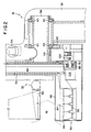
- Fig. 2 is a side cross-sectional view showing a bottom portion of an imaging device constructed in accordance with the present invention, which is incorporated into the system of Fig. 1;
- Fig. 3 is a side cross-sectional view showing a top portion of the imaging device of Fig. 2;
- Fig. 4 is a front plan view of the imaging device of Fig. 2;
- Fig. 5 is a front, cross-sectional view showing the filter selection assembly which is incorporated into the device of Fig. 2;
- Fig. 6 is a front view showing the steel belt drive mechanism which is incorporated into the device of Fig. 2;
- Fig. 7 is a top view showing a filter support structure constructed in accordance with the present invention; and
- Fig. 8 is a schematic diagram illustrating the control system for reading out the detector array.
-
- Referring to Fig. 1, an imaging system constructed in accordance with the present invention is identified by the
reference numeral 10. Generally, thesystem 10 includes: a digitalscan imaging device 12; a user interface 14, which may comprise a computer keyboard, for allowing the user to direct operation of thesystem 10; a controller 16, such as a computer, for operating theimaging device 12 and processing imaging information to construct a composite image of the patient's breast; and amonitor 20 for displaying the composite image. - Details of the
imaging device 12 are shown in Figs. 2-8. Theimaging device 12 includes animaging signal source 28 such as an x-ray tube, animaging signal receiver 30 such as a digital camera, acompression assembly 32 for compressing and immobilizing the patient'sbreast 18, ascanning assembly 34 for scanning the imaging signal across the patient'sbreast 18 and related components supported on apedestal 36. - In the illustrated embodiment, the
source 28,receiver 30 and portions of thecompression assembly 32 and scanningassembly 34 are rotatably mounted onpedestal 36 viashaft 38 andbearings 40 so as to allow for different approach angles for imaging the patient'sbreast 18, i.e., these components can be rotated about the patient'sbreast 18 in a direction generally parallel to the patient's chest wall to attain a desired initial or reference position for the imaging scan. Once such a desired position is attained, these components can be locked into position bybrake 42. Thebrake 42 can comprise, for example, anonrotatable gear section 44 which meshingly engages corresponding gear teeth provided onshaft 38 so as to lock theshaft 38 in place. Thegear section 44 can be engaged or disengaged as desired via an electromechanical clutch which can comprise a solenoid actuator. - The
compression assembly 32 compresses the patient'sbreast 18 to a more uniform thickness and concomitantly immobilizes the patient's breast to enhance the resulting image. As shown, this is accomplished by compressingly engaging the patient'sbreast 18 between the fixedupper surface 46 ofhousing 48 and thecompression paddle 50 which is moveable along rails 52. It will be appreciated thatpaddle 50 andupper surface 46 are formed from x-ray transparent materials. Thepaddle 50 can be manually moveable or motor driven. As shown, thepaddle 50 is driven bycompression motor 54, e.g., an electromechanical servo motor, via appropriatelinkage including shaft 56 which is located to avoid interference with thescanning assembly 34 as will be understood from the description below. A conventional release mechanism (not shown) is provided to allow for rapid release of the patient'sbreast 18 from compression in case of emergency. - The patient's breast is imaged by scanning an
imaging signal 58 across the patient'sbreast 18 and using thereceiver 30 to obtain imaging information during the scan. The illustratedimaging signal 58 comprises a narrow x-ray fan beam transmitted bysource 28 through x-ray absorbent collimator plates 60 (Fig. 5). The spacing ofcollimator plates 60 can be adjusted byscrews 62 to control the width ofsignal 58. In addition, the width of thesignal 58 can be controlled by providing lead slots, positioned upstream and downstream from the patient'sbreast 18. Although signals of various widths can be used for imaging, a narrow, collimated beam can reduce x-ray dose and the effects of scattered radiation. In addition, the illustratedsignal 58 has a depth, D, at least as great as the chest wall-to-nipple depth of the patient'sbreast 18. Although lesser signal depths could be employed, the illustratedsignal 58 allows for single pass, full field scanning, thereby enhancing imaging speed and simplifying processing. - The
receiver 30 receives theimaging signal 58 and transmits information, generally indicated byarrow 59 in Fig. 1, to the controller 16 based on the receivedsignal 58. Thereceiver 30 may comprise any of a variety of digital cameras. In this regard, thereceiver 30 can include an x-ray sensitive receiver for directly detecting an x-ray signal or phosphorescent screens which emit light upon excitation by x-ray radiation. Where phosphorescent screens are employed, lens based optics can be utilized to focus the emitted light on the focal plane of the imaging camera or fiber optics can be employed. - The illustrated
receiver 30 comprises a camera including a row ofphosphorescent screens 64 arranged to generally match thesignal 58 cross-section. Thescreens 64 are coupled via taperedfiber optic reducers 66 to anarray 132 of pixels such that each pixel is mapped to a corresponding screen location. The pixels can thus be read out as described below to yield an electronic signal which can be processed to provide an image of the patient's breast. The camera is moved in synchronization with thesignal 58 during scanning as will also be described below. - The
scanning assembly 34 includes ascanning motor 68, e.g., an electromechanical servo motor, for co-driving pivotal motion of thesource 28 and synchronous scanning motion of thereceiver 30. In the illustrated embodiment, this is accomplished by mounting thesource 28 and thereceiver 30 on apendulum 70 which, in turn, is rotatably carried onshaft 72 in alignment with thefocal spot 102 ofsource 28. Power is transmitted frommotor 68 viadrive belt 74 which is carried byoutput pulley 76 mounted onoutput shaft 78 andright transaxle pulley 80 mounted ontransaxle 82 which is coaxial withshaft 72. Also mounted ontransaxle 82 is lefttransaxle pulley 84 which carriesdrive belt 86.Drive belt 86 is carried at its lower extremity byencoder shaft pulley 88 which is mounted onencoder shaft 90. -
Steel belt pulley 92 is also mounted onencoder shaft 90 and has asteel belt 94 wrapped therearound as shown in Fig. 6. Thesteel belt 94, in turn, is attached to the left 96 and right 98 extremities ofarcuate cam 100. In this manner, rotation ofencoder shaft 90 causessteel belt pulley 92 to take-up and pay-outsteel belt 94 such thatsteel belt pulley 92 pendulantly tracks alongcam 100. Because thesteel belt pulley 92 is fixed topendulum 70, this pendulant tracking results in synchronized pivotal motion ofsource 28 and scanning motion ofreceiver 30. The illustrated steel belt drive reduces or eliminates backlash associated with start up acceleration and provides a smooth scanning motion thereby enhancing the resulting image. - In order to fully and accurately construct a composite image of the patient's
breast 18 based on a scan, it is necessary to frequently read out imaging data so that information regarding the entire area of interest is obtained and to accurately correlate the imaging data to the corresponding receiver/beam locations. This is accomplished by directly correlating positional information regarding the receiver 30 (which also reflects the position ofsignal 58 as the movement of thesource 28 andreceiver 30 is synchronized) and using this information for triggering imaging data acquisition and read out. In the illustrated embodiment, anencoder 104 such as a shaft-to-digital converter is mounted onencoder shaft 90. Theencoder 104 provides an electrical signal, generally identified by arrow 106 (Fig. 1), indicative of receiver position based on rotation ofencoder shaft 90. Thesignal 106, which can comprise a series of electrical pulses as a function of the scanning motion of thereceiver 30, directs operation of thereceiver 30 as will be described. - The illustrated
receiver 30 includes anarray 132 of pixels (Fig. 8) which are coupled tophosphorescent screens 64 viafiber optic reducers 66 as described above such that each pixel is mapped to a corresponding screen location. Thepixel array 132 is "M" pixels long and "N" pixels wide, where M and N can be selected based on the total area and desired spatial resolution of thescreens 64. In this regard, the area of the screens can be selected to substantially match the cross-section of the fan shapedimaging signal 58, and the spatial resolution is preferably sufficient to allow imaging of objects that may require an imaging aperture that is about 50 µm (microns) in size or even smaller. - During a scan of the patient's
breast 18, charge packets are synchronously shifted in pixel-to-pixel fashion across the width of thepixel array 132 such that the position of a particular charge packet withinpixel array 132 tracks a corresponding location within the patient'sbreast 18. In this manner, charge is integrated, as a charge packet moves across thepixel array 132, as a function of the imaging signal intensity incident on the associated phosphorescent screen location. When the charge packets reach the side of thepixel array 132, they are transferred, e.g., via a transfer gate, to read outarray 134 which may comprise a linear CCD array. The charge packets, and the imaging information contained therein, can then be clocked in a conventional shift register manner from the read outarray 134 for processing bycontroller 116. Thecontroller 116 receives the resulting read out signal and produces a digital signal representative of an image of the patient'sbreast 18, which image can then be displayed onhigh resolution monitor 20. - In order to accommodate charge integration as previously described and to produce a high fidelity image of the patient's breast, it is important that the charge shifting across the
pixel array 132 be accurately synchronized with the receiver scanning motion relative to the patient'sbreast 18. In the illustratedsystem 10, accurate synchronization is achieved by referencing such shifting directly to receiver motion as indicated by the output ofencoder 104. As previously noted, theencoder 104 produces a signal, such as a series of electrical pulses, as a function of receiver motion. This encoder output is communicated to a shift control circuit as illustrated schematically in Fig. 8. The shift control circuit can comprise, for example, a three phase shift circuit such as conventionally employed in CCD clocking networks. However, rather than synchronizing the shift cycle relative to clocked pulses, the phase shift circuit of the present invention synchronizes the shift cycle relative to the received encoder output. In this manner, shifting of thearray 132 is synchronized with the scanning motion ofreceiver 30 even when the scanning motion is disturbed by variances in drive speed or other irregularities. - The
imaging device 12 also includes a filter selection assembly 106 (Fig. 6). It has been found that the type of filter used, e.g., Aluminum, Molybdenum, Rhodium, Silver, etc., in combination with other operating parameters of theimaging device 12, can be selected based on particular imaging conditions to optimize the resulting image. In particular, different filters may be preferred based on differences in breast thickness and composition or density from one case to another. Thefilter selection assembly 106 thus allows for automatic filter selection based on particular imaging conditions. - In the illustrated embodiment, the
filter selection assembly 106 is used in conjunction with thecollimator plates 60. Theassembly 106 includes aplatform 108 which carries a number offilters 110. In principle, any useful number offilters 110 can be provided. The illustrated embodiment provides three filters 110 (or filter combinations as described below) which is believed to allow for adequate filtering flexibility for a broad range of applications. Theplatform 108 is mounted on thecollimator plates 60 by symmetrically arrangedleaf springs 112, which allow for movement of theplatform 108 relative to thesignal 58 so that any of thefilters 110 can be positioned in the signal's path. - Positioning of the
platform 108 is actuated by a pair ofsolenoids 114. Theplunger 116 of eachsolenoid 114 is connected to alever plate 118 via anarm 120. Thelever plates 118, which are pivotally mounted onpins 122, carrypegs 124 near an inner extremity thereof which are received withinslots 126 formed on the underside ofplatform 108. When one of thesolenoids 114 is energized, itsplunger 116 and thearm 120 connected to it are pulled in causing thelever plate 118 to pivot, thereby moving theplatform 108 so that adifferent filter 110 is positioned in the path ofsignal 58. The platform positions corresponding to the conditions where the left solenoid is energized, the right solenoid is energized or neither solenoid is energized allow for selection between threedifferent filters 110. - The
solenoids 114 are driven by a signal, generally identified byarrow 128 in Fig. 1, fromcontroller 116. In this regard, the user can direct selection of a desired filter by entering an appropriate command, generally indicated by arrow 130 in Fig. 1, into controller 16 via user interface 14, e.g., "SELECT FILTER 1." Alternatively, the controller 16 can direct selection of anappropriate filter 110 based on feedback indicative of breast thickness and composition or density. In the illustrated embodiment, the controller 16 receives feedback from thecompression assembly 32 as generally indicated byarrow 132 in Fig. 1. This feedback can be provided via an electrical signal from an encoder, potentiometer or the like incorporated into the drive mechanism of thecompression assembly 32 to indicate the position ofmoveable compression paddle 50. Additionally, feedback regarding the compression pressure may be provided via a pressure sensor, strain gauge or the like associated withcompression paddle 50 so as to provide an indication of breast thickness and density or composition. - A further indication of breast thickness and density or composition can be obtained via a test exposure. Specifically, such a test exposure can be performed as follows. After the patient is positioned and compressed, the
receiver 30 is positioned at the center of the imaging area and a very short exposure (e.g., 0.1 second) is taken using a standard filter and standard operating parameters. The data acquired in this mode, e.g., a histogram of radiation intensities, together with the compression assembly feedback as described above is then analyzed by the controller 16 as thereceiver 30 is moved to one side of the breast to begin a scan (this analysis can be completed in less than about a second). A look-up table of intensities generated with test objects of various thicknesses and beam hardening qualities stored by the controller 16 can be used in conjunction with the exposure andcompression assembly feedback 132 to estimate the thickness and composition or density of the breast under examination. This information in turn can be used by the controller to direct selection of anappropriate filter 110. - Feedback information can also be used to instantaneously optimize the operating parameters of the imaging signal source. For example, it is well known that radiographically dense breast tissue requires a higher exposure for optimal imaging. Such a higher exposure can be achieved during a scan by applying a greater photon flux, e.g., by increasing the output voltage of the source while maintaining adequate source current. In operation, a radiographically dense breast region, such as a region of glandular tissue, would be indicated by reduced intensities as measured by the
receiver 30. By monitoring such intensities during a scan and employing the controller 16 as described above to manipulate source operating parameters, the operating parameters can be continually optimized over the course of a scan. - Referring to Fig. 7, a top view of the
filter selection assembly 106 is shown. As previously noted,platform 108 is moveable so thatdifferent filters 110 can be positioned in the path of the imaging signal depending on particular conditions. It is also possible, in accordance with the present invention, to position more than one filter, or a single filter composed of two different materials, in the path of the imaging signal, so that the filtering characteristics can be separately optimized for different portions of the area of interest during a single scan. In this regard, by way of example, the retroglandular area (posterior part of the breast) is normally composed of fatty tissue whereas the anterior part tends to be fibrous and glandular. Accordingly, image quality can be enhanced according to the present invention by positioning different filters in the path of the posterior and anterior portions of the imaging signal. As shown, theplatform 108 ofassembly 106 carries filter pairs 110a and 110b, where the interface of the filter pairs 110a and 110b is generally aligned with the sourcefocal spot 102. - In summary, a digital scan imaging procedure is initiated by positioning the patient and operating the
compression assembly 32 to engage the patient'sbreast 18. The user can then direct the controller 16 to select anappropriate filter 110 for the imaging procedure. Alternatively, the controller 16 can direct selection of anappropriate filter 110 based on exposure and/orcompression assembly feedback 132. A side-to-side scan of the patient'sbreast 18 is then performed. At the conclusion of the scan, the controller 16 uses theimaging information 59 obtained in slice-by-slice fashion together with the known receiver position associated with each such slice to construct a composite image of the patient'sbreast 18 which is transmitted to monitor 20 as generally indicated byarrow 134.
Claims (8)
- An apparatus for use in imaging an area of interest within a patient's breast, the area of interest having a width relative to the patient's chest wall, the apparatus having source means (28) for transmitting a radiation signal through said area of interest within said patient's breast and receiving means (30), disposed in opposing relation to said source means with said patient's breast positioned therebetween, for receiving said transmitted radiation signal, characterized in that:said receiving means comprises an active array of detector elements (132) for accumulating electrical charge indicative of said received radiation signal, said active array of detector elements (132) having a width relative to said patient's chest wall which is less than a width of said area of interest within said patient's breast, and said apparatus further includes: scanning means (34) for scanning said receiving means by moving said active array of detector elements (132) in a direction generally parallel to said patient's chest wall across said width of said area of interest within said patient's breast during an exposure period in which said radiation signal is transmitted through said patient's breast; and processing means (16) for sequentially reading out said accumulated electrical charge from said active array of detector elements (132) at increments relative to the scan of said receiving means across said area of interest within said patient's breast during said exposure period thereby obtaining incremental imaging data, and for providing a composite image of said area of interest within said patient's breast based on said incremental imaging data.
- The apparatus as claimed in Claim 1, wherein said processing means (16) is operative for storing imaging information based on said accumulated electrical charge relating to a plurality of scan positions and for using said stored imaging information for forming a composite image of said area of interest within said patient's breast.
- The apparatus as claimed in Claim 1, further comprising encoding means (104) for encoding positional information regarding said receiving means relative to a scan across said area of interest within said patient's breast.
- The apparatus of Claim 3, wherein said width of said active array of detector elements is defined by a plurality of rows of detector elements, and said apparatus further comprises shifting means, operatively associated with said encoding means (104), for shifting electrical charge across said width of said active array.
- The apparatus as claimed in Claim 1, further comprising:collimator means (60) for collimating said radiation signal into a narrow beam, said narrow beam having a longitudinal length and a transverse width, wherein said width is substantially less than said length and less than said width of said area of interest within said patient's breast.
- The apparatus as claimed in Claim 5, further comprising:positioning means for positioning said collimator means such that said narrow beam is moveable across to said area of interest within said patient's breast.
- The apparatus as claimed in Claim 6, further comprising:filter support means (108), for supporting at least first and second radiation filters, wherein said first filter has performance characteristics different than that of said second filter, said filter support means being supportably connected to said collimator means to provide for a first positioning of said filter support means relative to said area of interest in unison with said positioning of said collimator means by said positioning means and a second positioning of said filter support means in a transverse direction relative to said collimator means; andselection means (114), operatively associated with said filter support means, for selectively positioning one of said first filter or said second filter in a path of said narrow beam by transversely moving at least one of said first and second filters relative to said collimator beams, wherein said apparatus allows for filter selection and movement of said narrow beam across said area of interest within said patient's breast.
- The apparatus as claimed in Claim 1, further comprising:filter support means (108) for simultaneously supporting a first filter element (110a) in a first position relative to said source means corresponding to a first portion of said area of interest within said patient's breast and a second filter element (110b) in a second position relative to said source means corresponding to a second portion of said area of interest within said patient's breast, said second filter element having filtering characteristics different than said first filter element, wherein a first portion of said radiation signal passes through said first filter element and a second portion of said radiation signal passes through said second filter element.
Applications Claiming Priority (3)
| Application Number | Priority Date | Filing Date | Title |
|---|---|---|---|
| US08/157,992 US5526394A (en) | 1993-11-26 | 1993-11-26 | Digital scan mammography apparatus |
| US157992 | 1993-11-26 | ||
| PCT/US1994/013505 WO1995015072A1 (en) | 1993-11-26 | 1994-11-22 | Digital scan mammography apparatus |
Publications (3)
| Publication Number | Publication Date |
|---|---|
| EP0730814A1 EP0730814A1 (en) | 1996-09-11 |
| EP0730814A4 EP0730814A4 (en) | 1996-12-27 |
| EP0730814B1 true EP0730814B1 (en) | 2002-02-27 |
Family
ID=22566230
Family Applications (1)
| Application Number | Title | Priority Date | Filing Date |
|---|---|---|---|
| EP95904116A Expired - Lifetime EP0730814B1 (en) | 1993-11-26 | 1994-11-22 | Scan mammography apparatus |
Country Status (6)
| Country | Link |
|---|---|
| US (1) | US5526394A (en) |
| EP (1) | EP0730814B1 (en) |
| JP (1) | JP3618753B2 (en) |
| CA (1) | CA2177489A1 (en) |
| DE (1) | DE69430002T2 (en) |
| WO (1) | WO1995015072A1 (en) |
Families Citing this family (129)
| Publication number | Priority date | Publication date | Assignee | Title |
|---|---|---|---|---|
| GB2289983B (en) | 1994-06-01 | 1996-10-16 | Simage Oy | Imaging devices,systems and methods |
| US6005911A (en) * | 1995-11-17 | 1999-12-21 | Trex Medical Corporation | Large area array, single exposure digital mammography |
| FI97665C (en) * | 1995-11-21 | 1997-01-27 | Planmed Oy | Procedures and apparatus for photographing an object |
| US7590083B2 (en) * | 1995-12-07 | 2009-09-15 | Transcore Link Logistics Corp. | Wireless packet data distributed communications system |
| CN1130855C (en) * | 1995-12-07 | 2003-12-10 | 维斯塔电信公司 | Wireless packet data distributed communications system |
| NL1003044C2 (en) * | 1996-05-06 | 1997-11-07 | Optische Ind Oede Oude Delftoe | X-ray imaging device. |
| US5815591A (en) * | 1996-07-10 | 1998-09-29 | R2 Technology, Inc. | Method and apparatus for fast detection of spiculated lesions in digital mammograms |
| JP4458553B2 (en) * | 1996-07-23 | 2010-04-28 | ザ ジェネラル ホスピタル コーポレイション | Tomographic apparatus for chest imaging |
| US5917929A (en) * | 1996-07-23 | 1999-06-29 | R2 Technology, Inc. | User interface for computer aided diagnosis system |
| US5776062A (en) * | 1996-10-15 | 1998-07-07 | Fischer Imaging Corporation | Enhanced breast imaging/biopsy system employing targeted ultrasound |
| US5757880A (en) * | 1997-01-08 | 1998-05-26 | Colomb; Denis | Apparatus, article of manufacture, and method for creation of an uncompressed image of compressed matter |
| US5917881A (en) * | 1997-05-20 | 1999-06-29 | Fischer Imaging Corporation | Digital scan mammography apparatus utilizing velocity adaptive feedback and method |
| US6246782B1 (en) | 1997-06-06 | 2001-06-12 | Lockheed Martin Corporation | System for automated detection of cancerous masses in mammograms |
| USD408916S (en) | 1998-02-06 | 1999-04-27 | Canon Kabushiki Kaisha | X-ray digital camera |
| DE19824496A1 (en) * | 1998-06-02 | 1999-12-09 | Siemens Ag | Device with an operating parameter, the value of which can be preselected via a control unit |
| US6669483B1 (en) * | 1998-09-24 | 2003-12-30 | West Virginia University | Instrumented breast model |
| US9029793B2 (en) * | 1998-11-05 | 2015-05-12 | Siemens Aktiengesellschaft | Imaging device |
| WO2000051484A2 (en) | 1998-11-25 | 2000-09-08 | Fischer Imaging Corporation | User interface system for mammographic imager |
| FR2786388B1 (en) | 1998-11-27 | 2001-02-16 | Ge Medical Syst Sa | METHOD FOR DETECTING FABRIC OF A SPECIFIC NATURE IN DIGITAL RADIOLOGY AND ITS USE FOR ADJUSTING THE EXPOSURE PARAMETERS |
| FI106346B (en) * | 1998-12-14 | 2001-01-15 | Planmed Oy | Digital imaging method and devices for digital imaging |
| US6249564B1 (en) * | 1999-03-19 | 2001-06-19 | Trustees Of Tufts College | Method and system for body composition analysis using x-ray attenuation |
| US6684097B1 (en) * | 1999-04-22 | 2004-01-27 | University Of Miami | Intraoperative monitoring of temperature-induced tissue changes with a high-resolution digital x-ray system during thermotherapy |
| AU4480700A (en) | 1999-04-22 | 2000-11-10 | University Of Miami | Intraoperative monitoring of temperature-induced tissue changes with a high-resolution digital x-ray system during thermotherapy |
| EP1719542A1 (en) | 1999-04-22 | 2006-11-08 | The University of Miami | Intraoperative monitoring of temperature-induced tissue changes with a high-resolution digital X-ray system during thermotherapy |
| US6987831B2 (en) * | 1999-11-18 | 2006-01-17 | University Of Rochester | Apparatus and method for cone beam volume computed tomography breast imaging |
| US6480565B1 (en) † | 1999-11-18 | 2002-11-12 | University Of Rochester | Apparatus and method for cone beam volume computed tomography breast imaging |
| US6496557B2 (en) | 2000-02-09 | 2002-12-17 | Hologic, Inc. | Two-dimensional slot x-ray bone densitometry, radiography and tomography |
| RU2171629C1 (en) * | 2000-05-18 | 2001-08-10 | Научно-исследовательский институт импульсной техники | Digital scanning mammograph |
| FR2819329B1 (en) * | 2001-01-11 | 2003-06-06 | Ge Med Sys Global Tech Co Llc | METHOD AND DEVICE FOR AUTOMATIC DETECTION OF A GRADUATED COMPRESSION PELOT OF A MAMMOGRAPHY APPARATUS |
| US6751285B2 (en) * | 2001-11-21 | 2004-06-15 | General Electric Company | Dose management system for mammographic tomosynthesis |
| US6741673B2 (en) * | 2002-08-06 | 2004-05-25 | Mikhail Kamenetsky | Mammography device and method utilizing optimally curved support plate configuration for accuracy in imaging and diagnosis |
| GB0224689D0 (en) | 2002-10-23 | 2002-12-04 | Simage Oy | Formation of contacts on semiconductor substrates |
| DE60328904D1 (en) * | 2002-10-25 | 2009-10-01 | Ipl Intellectual Property Lice | SWITCHING SUPPLY AND METHOD |
| ATE322499T1 (en) * | 2002-11-11 | 2006-04-15 | METHOD FOR PRODUCING 2-KETO-L-GULONIC ACID-C-4 C-10/SB-ALKYLE ESTERS | |
| CN101449979A (en) * | 2002-11-12 | 2009-06-10 | 罗切斯特大学 | Apparatus and method for cone beam volume computed tomography breast imaging |
| US7123684B2 (en) * | 2002-11-27 | 2006-10-17 | Hologic, Inc. | Full field mammography with tissue exposure control, tomosynthesis, and dynamic field of view processing |
| US10638994B2 (en) | 2002-11-27 | 2020-05-05 | Hologic, Inc. | X-ray mammography with tomosynthesis |
| US7577282B2 (en) | 2002-11-27 | 2009-08-18 | Hologic, Inc. | Image handling and display in X-ray mammography and tomosynthesis |
| US8571289B2 (en) | 2002-11-27 | 2013-10-29 | Hologic, Inc. | System and method for generating a 2D image from a tomosynthesis data set |
| US8565372B2 (en) | 2003-11-26 | 2013-10-22 | Hologic, Inc | System and method for low dose tomosynthesis |
| US7616801B2 (en) | 2002-11-27 | 2009-11-10 | Hologic, Inc. | Image handling and display in x-ray mammography and tomosynthesis |
| US7406150B2 (en) * | 2002-11-29 | 2008-07-29 | Hologic, Inc. | Distributed architecture for mammographic image acquisition and processing |
| FI117542B (en) | 2002-12-04 | 2006-11-30 | Planmed Oy | Digital mammography imaging procedure and digital mammography imaging device |
| WO2004082480A1 (en) * | 2003-03-20 | 2004-09-30 | African Medical Imaging (Pty) Ltd | Digital scan mammograph imaging apparatus |
| EP1618411A4 (en) | 2003-04-11 | 2012-04-25 | Fischer Imaging Corp | DISCHARGE REJECTION FOR COMPOSITE MEDICAL IMAGING SYSTEMS |
| US7319734B2 (en) * | 2003-04-11 | 2008-01-15 | Hologic, Inc. | Method and apparatus for blocking radiographic scatter |
| DE10324911B4 (en) * | 2003-05-30 | 2005-08-18 | Siemens Ag | X-ray device with partial digital detector and method for operating such |
| US6846289B2 (en) | 2003-06-06 | 2005-01-25 | Fischer Imaging Corporation | Integrated x-ray and ultrasound medical imaging system |
| JP3759524B2 (en) * | 2003-10-17 | 2006-03-29 | 株式会社リガク | X-ray analyzer |
| EP1526551A1 (en) | 2003-10-24 | 2005-04-27 | Agfa-Gevaert | Stimulable phosphor screens or panels and manufacturing control thereof |
| GB0411403D0 (en) * | 2004-05-21 | 2004-06-23 | Tissuomics Ltd | Irradiating body tissue |
| US7662082B2 (en) | 2004-11-05 | 2010-02-16 | Theragenics Corporation | Expandable brachytherapy device |
| EP2602743B1 (en) | 2004-11-15 | 2014-11-05 | Hologic, Inc. | Matching geometry generation and display of mammograms and tomosynthesis images |
| EP3106094B1 (en) | 2004-11-26 | 2021-09-08 | Hologic, Inc. | Integrated multi-mode mammography/tomosynthesis x-ray system |
| US7505554B2 (en) * | 2005-07-25 | 2009-03-17 | Digimd Corporation | Apparatus and methods of an X-ray and tomosynthesis and dual spectra machine |
| US11020086B2 (en) | 2005-09-01 | 2021-06-01 | Shih-Ping Wang | Breast ultrasound scanning |
| WO2013078476A1 (en) | 2011-11-27 | 2013-05-30 | Hologic, Inc. | System and method for generating a 2d image using mammography and/or tomosynthesis image data |
| US10008184B2 (en) | 2005-11-10 | 2018-06-26 | Hologic, Inc. | System and method for generating a 2D image using mammography and/or tomosynthesis image data |
| US7465268B2 (en) | 2005-11-18 | 2008-12-16 | Senorx, Inc. | Methods for asymmetrical irradiation of a body cavity |
| CN100473343C (en) * | 2005-11-23 | 2009-04-01 | 北京东方逸腾数码医疗设备技术有限公司 | Virtual control method of digital light concentrator |
| CN2836727Y (en) * | 2005-11-23 | 2006-11-15 | 北京东方逸腾数码医疗设备技术有限公司 | Digital light beam unit |
| WO2007095330A2 (en) | 2006-02-15 | 2007-08-23 | Hologic Inc | Breast biopsy and needle localization using tomosynthesis systems |
| CN105596022B (en) * | 2006-02-27 | 2020-05-22 | 罗切斯特大学 | Method and device for cone beam CT dynamic imaging |
| US20080037703A1 (en) * | 2006-08-09 | 2008-02-14 | Digimd Corporation | Three dimensional breast imaging |
| FR2905256B1 (en) * | 2006-09-05 | 2008-11-21 | Gen Electric | METHOD FOR OBTAINING A TOMOSYNTHESIS IMAGE |
| US7676019B2 (en) * | 2007-01-31 | 2010-03-09 | Sectra Mamea Ab | Compression arrangement |
| GB2465726A (en) * | 2007-08-23 | 2010-06-02 | Fischer Medical Technologies Inc | Improved computed tomography breast imaging and biopsy system |
| US7630533B2 (en) | 2007-09-20 | 2009-12-08 | Hologic, Inc. | Breast tomosynthesis with display of highlighted suspected calcifications |
| FI20075701A7 (en) * | 2007-10-03 | 2008-12-03 | Planmed Oy | Arrangement and method in digital mammography imaging |
| DE102007057287B4 (en) * | 2007-11-28 | 2016-07-07 | Siemens Healthcare Gmbh | Clutch and mammography device |
| US8023767B1 (en) | 2008-03-10 | 2011-09-20 | University Of Rochester | Method and apparatus for 3D metal and high-density artifact correction for cone-beam and fan-beam CT imaging |
| US7792245B2 (en) * | 2008-06-24 | 2010-09-07 | Hologic, Inc. | Breast tomosynthesis system with shifting face shield |
| US7991106B2 (en) | 2008-08-29 | 2011-08-02 | Hologic, Inc. | Multi-mode tomosynthesis/mammography gain calibration and image correction using gain map information from selected projection angles |
| US9579524B2 (en) | 2009-02-11 | 2017-02-28 | Hologic, Inc. | Flexible multi-lumen brachytherapy device |
| US9248311B2 (en) | 2009-02-11 | 2016-02-02 | Hologic, Inc. | System and method for modifying a flexibility of a brachythereapy catheter |
| US10207126B2 (en) | 2009-05-11 | 2019-02-19 | Cytyc Corporation | Lumen visualization and identification system for multi-lumen balloon catheter |
| DE102009021024A1 (en) * | 2009-05-13 | 2010-11-18 | Siemens Aktiengesellschaft | Method of preparing a treatment plan for a particle therapy and a filter device for a particle therapy system |
| JP5572040B2 (en) * | 2009-09-28 | 2014-08-13 | 富士フイルム株式会社 | Radiography equipment |
| CN102481146B (en) | 2009-10-08 | 2016-08-17 | 霍罗吉克公司 | Breast needle biopsy system and method of use thereof |
| WO2011153555A2 (en) * | 2010-06-03 | 2011-12-08 | Caperay Medical (Pty) Ltd | Dual-modality scanning system for detecting breast cancer |
| JP2012035068A (en) * | 2010-07-16 | 2012-02-23 | Fujifilm Corp | Radiation image processor, method, and program |
| US9352172B2 (en) | 2010-09-30 | 2016-05-31 | Hologic, Inc. | Using a guide member to facilitate brachytherapy device swap |
| CA2813591C (en) | 2010-10-05 | 2020-09-22 | Hologic, Inc. | Upright x-ray breast imaging with a ct mode, multiple tomosynthesis modes, and a mammography mode |
| US20120133600A1 (en) | 2010-11-26 | 2012-05-31 | Hologic, Inc. | User interface for medical image review workstation |
| US10342992B2 (en) | 2011-01-06 | 2019-07-09 | Hologic, Inc. | Orienting a brachytherapy applicator |
| JP6057922B2 (en) | 2011-03-08 | 2017-01-11 | ホロジック, インコーポレイテッドHologic, Inc. | System and method for dual energy and / or contrast enhanced breast imaging for screening, diagnosis and biopsy |
| KR102014861B1 (en) * | 2011-12-29 | 2019-08-27 | 제너럴 일렉트릭 캄파니 | Digital mammography apparatus |
| WO2013123091A1 (en) | 2012-02-13 | 2013-08-22 | Hologic, Inc. | System and method for navigating a tomosynthesis stack using synthesized image data |
| JP6004714B2 (en) * | 2012-04-12 | 2016-10-12 | キヤノン株式会社 | Subject information acquisition apparatus and control method thereof |
| JP2014045793A (en) * | 2012-08-29 | 2014-03-17 | Sony Corp | Signal processing system, signal processing apparatus, and program |
| DE102012219051A1 (en) * | 2012-10-18 | 2014-04-24 | Klinikum Der Universität München | Selection of a radiation form filter |
| CN105025793B (en) * | 2012-12-10 | 2017-11-07 | 通用电气公司 | X-ray machine |
| US9364191B2 (en) | 2013-02-11 | 2016-06-14 | University Of Rochester | Method and apparatus of spectral differential phase-contrast cone-beam CT and hybrid cone-beam CT |
| US10624598B2 (en) | 2013-03-15 | 2020-04-21 | Hologic, Inc. | System and method for navigating a tomosynthesis stack including automatic focusing |
| WO2014151646A1 (en) | 2013-03-15 | 2014-09-25 | Hologic Inc. | Tomosynthesis-guided biopsy in prone |
| JP6307590B2 (en) * | 2013-03-29 | 2018-04-04 | ゼネラル・エレクトリック・カンパニイ | Mammography equipment |
| US10004470B2 (en) | 2013-07-18 | 2018-06-26 | General Electric Company | Breast imaging system giving feedback information to the patient and method using thereof |
| ES2954561T3 (en) | 2013-10-09 | 2023-11-23 | Hologic Inc | X-ray breast tomosynthesis that enhances spatial resolution, even in the thickness direction of a flattened breast |
| US10045749B2 (en) | 2013-10-22 | 2018-08-14 | Koninklijke Philips N.V. | X-ray system, in particular a tomosynthesis system and a method for acquiring an image of an object |
| EP3646798B1 (en) | 2013-10-24 | 2023-09-27 | Hologic, Inc. | System and method for navigating x-ray guided breast biopsy |
| DE102014203465B4 (en) * | 2014-02-26 | 2026-05-07 | Siemens Healthineers Ag | Selection of a radiation shape filter from a plurality of radiation shape filters |
| US10111631B2 (en) | 2014-02-28 | 2018-10-30 | Hologic, Inc. | System and method for generating and displaying tomosynthesis image slabs |
| JP6200839B2 (en) * | 2014-03-19 | 2017-09-20 | 富士フイルム株式会社 | Breast thickness measuring device, breast thickness measuring method and radiography system |
| CN107405124A (en) * | 2014-12-26 | 2017-11-28 | 射线科学有限公司 | Lifting device for pressure paddle and radiographic apparatus comprising the lifting device |
| WO2017091787A1 (en) | 2015-11-25 | 2017-06-01 | The Regents Of The University Of California | 3d-beam modulation filter for equalizing dose and image quality in breast ct |
| WO2017185028A1 (en) | 2016-04-22 | 2017-10-26 | Hologic, Inc. | Tomosynthesis with shifting focal spot x-ray system using an addressable array |
| EP3600047A1 (en) | 2017-03-30 | 2020-02-05 | Hologic, Inc. | System and method for hierarchical multi-level feature image synthesis and representation |
| CN110662489B (en) | 2017-03-30 | 2024-08-02 | 豪洛捷公司 | Systems and methods for targeted object enhancement to generate synthetic breast tissue images |
| CN110621233B (en) | 2017-03-30 | 2023-12-12 | 豪洛捷公司 | Methods for processing breast tissue image data |
| WO2018236565A1 (en) | 2017-06-20 | 2018-12-27 | Hologic, Inc. | Dynamic self-learning medical image method and system |
| DE202018006903U1 (en) | 2017-08-16 | 2024-07-29 | Hologic Inc. | Techniques for patient motion artifact compensation in breast imaging |
| EP3449835B1 (en) | 2017-08-22 | 2023-01-11 | Hologic, Inc. | Computed tomography system and method for imaging multiple anatomical targets |
| CN112292064A (en) * | 2018-03-25 | 2021-01-29 | 王士平 | breast ultrasound scan |
| US11090017B2 (en) | 2018-09-13 | 2021-08-17 | Hologic, Inc. | Generating synthesized projection images for 3D breast tomosynthesis or multi-mode x-ray breast imaging |
| CN112804944B (en) | 2018-09-24 | 2024-07-23 | 豪洛捷公司 | Breast mapping and abnormality localization |
| JP7482860B2 (en) | 2018-09-28 | 2024-05-14 | ホロジック, インコーポレイテッド | System and method for generating synthetic breast tissue images with high density element suppression - Patents.com |
| US12170140B2 (en) | 2018-11-25 | 2024-12-17 | Hologic, Inc. | Customizable multimodality image hanging protocols |
| WO2020205610A1 (en) | 2019-03-29 | 2020-10-08 | Hologic, Inc. | Snip-triggered digital image report generation |
| EP3832689A3 (en) | 2019-12-05 | 2021-08-11 | Hologic, Inc. | Systems and methods for improved x-ray tube life |
| JP2023519878A (en) | 2020-03-27 | 2023-05-15 | ホロジック, インコーポレイテッド | Systems and methods for correlating regions of interest in multiple imaging modalities |
| US11471118B2 (en) | 2020-03-27 | 2022-10-18 | Hologic, Inc. | System and method for tracking x-ray tube focal spot position |
| AU2021241536A1 (en) | 2020-03-27 | 2022-08-18 | Hologic, Inc. | Systems and methods for identifying regions of interest in multiple imaging modalities |
| US20220164951A1 (en) | 2020-11-20 | 2022-05-26 | Hologic, Inc. | Systems and methods for using ai to identify regions of interest in medical images |
| US11786191B2 (en) | 2021-05-17 | 2023-10-17 | Hologic, Inc. | Contrast-enhanced tomosynthesis with a copper filter |
| US12186119B2 (en) | 2021-10-05 | 2025-01-07 | Hologic, Inc. | Interactive model interface for image selection in medical imaging systems |
| US12254586B2 (en) | 2021-10-25 | 2025-03-18 | Hologic, Inc. | Auto-focus tool for multimodality image review |
| IL313196A (en) | 2021-11-29 | 2024-07-01 | Hologic Inc | Systems and methods for determining correlations between objects of interest |
| US12414217B2 (en) | 2022-02-07 | 2025-09-09 | Hologic, Inc. | Systems and methods for adaptively controlling filament current in an X-ray tube |
| US11684320B1 (en) | 2022-09-12 | 2023-06-27 | Izotropic Corporation | Linear motor assembly for X-ray computed tomography system |
Family Cites Families (14)
| Publication number | Priority date | Publication date | Assignee | Title |
|---|---|---|---|---|
| US4096391A (en) * | 1976-10-15 | 1978-06-20 | The Board Of Trustees Of The University Of Alabama | Method and apparatus for reduction of scatter in diagnostic radiology |
| US4179100A (en) * | 1977-08-01 | 1979-12-18 | University Of Pittsburgh | Radiography apparatus |
| US4203037A (en) * | 1977-08-01 | 1980-05-13 | University Of Pittsburgh | Collimated radiation apparatus |
| US4157572A (en) * | 1977-09-12 | 1979-06-05 | University Of Pittsburgh | Superimposition of television images |
| US4383327A (en) * | 1980-12-01 | 1983-05-10 | University Of Utah | Radiographic systems employing multi-linear arrays of electronic radiation detectors |
| DE3339775A1 (en) * | 1983-11-03 | 1985-05-15 | Siemens AG, 1000 Berlin und 8000 München | X-RAY DIAGNOSTIC DEVICE WITH RADIATION FILTERS |
| US4696022A (en) * | 1984-01-27 | 1987-09-22 | University Of Pittsburgh | Stereoscopic radiography apparatus and method |
| US4946238A (en) * | 1984-01-27 | 1990-08-07 | University Of Pittsburgh | Fiber optic coupler |
| US4692937A (en) * | 1984-05-02 | 1987-09-08 | University Of Pittsburgh | Radiography apparatus and method |
| US4763343A (en) * | 1986-09-23 | 1988-08-09 | Yanaki Nicola E | Method and structure for optimizing radiographic quality by controlling X-ray tube voltage, current, focal spot size and exposure time |
| US4998270A (en) * | 1989-09-06 | 1991-03-05 | General Electric Company | Mammographic apparatus with collimated controllable X-ray intensity and plurality filters |
| US5142557A (en) * | 1990-12-21 | 1992-08-25 | Photometrics Ltd. | CCD and phosphor screen digital radiology apparatus and method for high resolution mammography |
| US5289520A (en) * | 1991-11-27 | 1994-02-22 | Lorad Corporation | Stereotactic mammography imaging system with prone position examination table and CCD camera |
| SE9201157D0 (en) * | 1992-04-10 | 1992-04-10 | Siemens Elema Ab | MADE TO CONTROL THE COMPRESSION POWER OF AN X-ray machine for mammogram examinations and device performed by the kit |
-
1993
- 1993-11-26 US US08/157,992 patent/US5526394A/en not_active Expired - Lifetime
-
1994
- 1994-11-22 JP JP51520295A patent/JP3618753B2/en not_active Expired - Fee Related
- 1994-11-22 EP EP95904116A patent/EP0730814B1/en not_active Expired - Lifetime
- 1994-11-22 DE DE69430002T patent/DE69430002T2/en not_active Expired - Fee Related
- 1994-11-22 CA CA002177489A patent/CA2177489A1/en not_active Abandoned
- 1994-11-22 WO PCT/US1994/013505 patent/WO1995015072A1/en not_active Ceased
Also Published As
| Publication number | Publication date |
|---|---|
| JPH09505498A (en) | 1997-06-03 |
| DE69430002T2 (en) | 2002-10-24 |
| CA2177489A1 (en) | 1995-06-01 |
| US5526394A (en) | 1996-06-11 |
| JP3618753B2 (en) | 2005-02-09 |
| EP0730814A1 (en) | 1996-09-11 |
| WO1995015072A1 (en) | 1995-06-01 |
| EP0730814A4 (en) | 1996-12-27 |
| DE69430002D1 (en) | 2002-04-04 |
Similar Documents
| Publication | Publication Date | Title |
|---|---|---|
| US5526394A (en) | Digital scan mammography apparatus | |
| US5365562A (en) | Digital imaging apparatus | |
| US4203037A (en) | Collimated radiation apparatus | |
| US7286636B2 (en) | Flat panel detector based slot scanning configuration | |
| US6846289B2 (en) | Integrated x-ray and ultrasound medical imaging system | |
| US6574296B2 (en) | Computer tomography unit and method for operating same | |
| DE10255856B4 (en) | Procedure and medical imaging system | |
| US5142557A (en) | CCD and phosphor screen digital radiology apparatus and method for high resolution mammography | |
| EP2830505B1 (en) | Hybrid pci system for medical radiographic imaging | |
| US6175117B1 (en) | Tissue analysis apparatus | |
| JP6753708B2 (en) | Medical diagnostic imaging equipment | |
| WO2014100063A1 (en) | Medical radiographic grating based differential phase contrast imaging | |
| CN101156781A (en) | Double-irradiation breast imaging device and breast imaging method using the device | |
| US6940942B2 (en) | Scanning-based detection of ionizing radiation for tomosynthesis | |
| US7164748B2 (en) | Arrangement and method for obtaining imaging data | |
| US4164657A (en) | Apparatus for tomography | |
| US20040120457A1 (en) | Scatter reducing device for imaging | |
| EP0983020A1 (en) | Tissue analysis apparatus | |
| CA2530390A1 (en) | Scanning-based detection of ionizing radiation for tomosynthesis | |
| US7020237B2 (en) | Scanning-based detection of ionizing radiation for tomosynthesis | |
| WO2003055393A1 (en) | Scatter reducing imaging device | |
| JP2685462B2 (en) | Energy difference image capturing device. | |
| JPH06285057A (en) | X-ray transmission image photographing device | |
| WO2025123035A1 (en) | System and method for cabinet x-ray systems with 3-d optical imaging reconstruction | |
| RU2171627C2 (en) | Non-invasive method and device for diagnosing mammary gland cancer |
Legal Events
| Date | Code | Title | Description |
|---|---|---|---|
| PUAI | Public reference made under article 153(3) epc to a published international application that has entered the european phase |
Free format text: ORIGINAL CODE: 0009012 |
|
| 17P | Request for examination filed |
Effective date: 19960617 |
|
| AK | Designated contracting states |
Kind code of ref document: A1 Designated state(s): DE FR IT SE |
|
| A4 | Supplementary search report drawn up and despatched |
Effective date: 19961106 |
|
| AK | Designated contracting states |
Kind code of ref document: A4 Designated state(s): DE FR IT SE |
|
| 17Q | First examination report despatched |
Effective date: 19981207 |
|
| RTI1 | Title (correction) |
Free format text: SCAN MAMMOGRAPHY APPARATUS |
|
| GRAG | Despatch of communication of intention to grant |
Free format text: ORIGINAL CODE: EPIDOS AGRA |
|
| GRAG | Despatch of communication of intention to grant |
Free format text: ORIGINAL CODE: EPIDOS AGRA |
|
| GRAH | Despatch of communication of intention to grant a patent |
Free format text: ORIGINAL CODE: EPIDOS IGRA |
|
| GRAH | Despatch of communication of intention to grant a patent |
Free format text: ORIGINAL CODE: EPIDOS IGRA |
|
| GRAA | (expected) grant |
Free format text: ORIGINAL CODE: 0009210 |
|
| AK | Designated contracting states |
Kind code of ref document: B1 Designated state(s): DE FR IT SE |
|
| REF | Corresponds to: |
Ref document number: 69430002 Country of ref document: DE Date of ref document: 20020404 |
|
| ET | Fr: translation filed | ||
| PLBE | No opposition filed within time limit |
Free format text: ORIGINAL CODE: 0009261 |
|
| STAA | Information on the status of an ep patent application or granted ep patent |
Free format text: STATUS: NO OPPOSITION FILED WITHIN TIME LIMIT |
|
| 26N | No opposition filed |
Effective date: 20021128 |
|
| PGFP | Annual fee paid to national office [announced via postgrant information from national office to epo] |
Ref country code: FR Payment date: 20051125 Year of fee payment: 12 |
|
| PGFP | Annual fee paid to national office [announced via postgrant information from national office to epo] |
Ref country code: SE Payment date: 20051128 Year of fee payment: 12 |
|
| PGFP | Annual fee paid to national office [announced via postgrant information from national office to epo] |
Ref country code: DE Payment date: 20051201 Year of fee payment: 12 |
|
| PG25 | Lapsed in a contracting state [announced via postgrant information from national office to epo] |
Ref country code: SE Free format text: LAPSE BECAUSE OF NON-PAYMENT OF DUE FEES Effective date: 20061123 |
|
| PGFP | Annual fee paid to national office [announced via postgrant information from national office to epo] |
Ref country code: IT Payment date: 20061130 Year of fee payment: 13 |
|
| PG25 | Lapsed in a contracting state [announced via postgrant information from national office to epo] |
Ref country code: DE Free format text: LAPSE BECAUSE OF NON-PAYMENT OF DUE FEES Effective date: 20070601 |
|
| EUG | Se: european patent has lapsed | ||
| REG | Reference to a national code |
Ref country code: FR Ref legal event code: ST Effective date: 20070731 |
|
| PG25 | Lapsed in a contracting state [announced via postgrant information from national office to epo] |
Ref country code: FR Free format text: LAPSE BECAUSE OF NON-PAYMENT OF DUE FEES Effective date: 20061130 |
|
| PG25 | Lapsed in a contracting state [announced via postgrant information from national office to epo] |
Ref country code: IT Free format text: LAPSE BECAUSE OF NON-PAYMENT OF DUE FEES Effective date: 20071122 |