EP3646798B1 - System and method for navigating x-ray guided breast biopsy - Google Patents
System and method for navigating x-ray guided breast biopsy Download PDFInfo
- Publication number
- EP3646798B1 EP3646798B1 EP19213173.8A EP19213173A EP3646798B1 EP 3646798 B1 EP3646798 B1 EP 3646798B1 EP 19213173 A EP19213173 A EP 19213173A EP 3646798 B1 EP3646798 B1 EP 3646798B1
- Authority
- EP
- European Patent Office
- Prior art keywords
- image
- images
- breast
- biopsy
- tomosynthesis
- Prior art date
- Legal status (The legal status is an assumption and is not a legal conclusion. Google has not performed a legal analysis and makes no representation as to the accuracy of the status listed.)
- Active
Links
- 238000000034 method Methods 0.000 title claims description 106
- 210000000481 breast Anatomy 0.000 title claims description 105
- 238000001574 biopsy Methods 0.000 title claims description 90
- 238000003384 imaging method Methods 0.000 claims description 97
- 230000003902 lesion Effects 0.000 claims description 50
- 239000002872 contrast media Substances 0.000 claims description 36
- 230000009977 dual effect Effects 0.000 claims description 21
- 239000002131 composite material Substances 0.000 claims description 18
- 230000008685 targeting Effects 0.000 claims description 15
- 230000002596 correlated effect Effects 0.000 claims description 2
- 238000005516 engineering process Methods 0.000 description 48
- 210000001519 tissue Anatomy 0.000 description 40
- 208000004434 Calcinosis Diseases 0.000 description 36
- 230000008569 process Effects 0.000 description 27
- 230000002308 calcification Effects 0.000 description 24
- 238000009607 mammography Methods 0.000 description 21
- 230000000875 corresponding effect Effects 0.000 description 18
- 230000004044 response Effects 0.000 description 15
- 238000010586 diagram Methods 0.000 description 14
- 238000012552 review Methods 0.000 description 13
- 238000012800 visualization Methods 0.000 description 11
- 230000006835 compression Effects 0.000 description 9
- 238000007906 compression Methods 0.000 description 9
- 238000012545 processing Methods 0.000 description 9
- 238000003860 storage Methods 0.000 description 9
- 238000003745 diagnosis Methods 0.000 description 7
- 238000013275 image-guided biopsy Methods 0.000 description 6
- 230000005856 abnormality Effects 0.000 description 5
- 238000012216 screening Methods 0.000 description 5
- 238000012795 verification Methods 0.000 description 5
- 238000013459 approach Methods 0.000 description 4
- 238000001514 detection method Methods 0.000 description 4
- 235000019580 granularity Nutrition 0.000 description 4
- 230000007246 mechanism Effects 0.000 description 4
- 230000000007 visual effect Effects 0.000 description 4
- 206010006187 Breast cancer Diseases 0.000 description 3
- 208000026310 Breast neoplasm Diseases 0.000 description 3
- 230000004913 activation Effects 0.000 description 3
- 230000008901 benefit Effects 0.000 description 3
- 238000001914 filtration Methods 0.000 description 3
- 238000002347 injection Methods 0.000 description 3
- 239000007924 injection Substances 0.000 description 3
- 238000013507 mapping Methods 0.000 description 3
- 238000001356 surgical procedure Methods 0.000 description 3
- 230000002159 abnormal effect Effects 0.000 description 2
- 230000009471 action Effects 0.000 description 2
- 210000004204 blood vessel Anatomy 0.000 description 2
- 210000004027 cell Anatomy 0.000 description 2
- 238000004891 communication Methods 0.000 description 2
- 238000010276 construction Methods 0.000 description 2
- 238000013213 extrapolation Methods 0.000 description 2
- 230000000977 initiatory effect Effects 0.000 description 2
- 230000001360 synchronised effect Effects 0.000 description 2
- 230000002194 synthesizing effect Effects 0.000 description 2
- ZCYVEMRRCGMTRW-UHFFFAOYSA-N 7553-56-2 Chemical compound [I] ZCYVEMRRCGMTRW-UHFFFAOYSA-N 0.000 description 1
- OYPRJOBELJOOCE-UHFFFAOYSA-N Calcium Chemical compound [Ca] OYPRJOBELJOOCE-UHFFFAOYSA-N 0.000 description 1
- RYGMFSIKBFXOCR-UHFFFAOYSA-N Copper Chemical compound [Cu] RYGMFSIKBFXOCR-UHFFFAOYSA-N 0.000 description 1
- 241000577979 Peromyscus spicilegus Species 0.000 description 1
- 230000003213 activating effect Effects 0.000 description 1
- 230000005540 biological transmission Effects 0.000 description 1
- 229910052791 calcium Inorganic materials 0.000 description 1
- 239000011575 calcium Substances 0.000 description 1
- 238000006243 chemical reaction Methods 0.000 description 1
- 229910052802 copper Inorganic materials 0.000 description 1
- 239000010949 copper Substances 0.000 description 1
- 208000031513 cyst Diseases 0.000 description 1
- 238000002059 diagnostic imaging Methods 0.000 description 1
- 238000009826 distribution Methods 0.000 description 1
- 230000000694 effects Effects 0.000 description 1
- 238000011156 evaluation Methods 0.000 description 1
- 230000002068 genetic effect Effects 0.000 description 1
- 230000003100 immobilizing effect Effects 0.000 description 1
- 229910052740 iodine Inorganic materials 0.000 description 1
- 239000011630 iodine Substances 0.000 description 1
- 230000009191 jumping Effects 0.000 description 1
- 230000004807 localization Effects 0.000 description 1
- 210000001165 lymph node Anatomy 0.000 description 1
- 238000002595 magnetic resonance imaging Methods 0.000 description 1
- 238000013188 needle biopsy Methods 0.000 description 1
- 238000003825 pressing Methods 0.000 description 1
- 230000002441 reversible effect Effects 0.000 description 1
- 238000004513 sizing Methods 0.000 description 1
- 238000012358 sourcing Methods 0.000 description 1
- 238000006467 substitution reaction Methods 0.000 description 1
- 210000000779 thoracic wall Anatomy 0.000 description 1
- 238000012285 ultrasound imaging Methods 0.000 description 1
Images


Classifications
-
- A—HUMAN NECESSITIES
- A61—MEDICAL OR VETERINARY SCIENCE; HYGIENE
- A61B—DIAGNOSIS; SURGERY; IDENTIFICATION
- A61B6/00—Apparatus for radiation diagnosis, e.g. combined with radiation therapy equipment
- A61B6/04—Positioning of patients; Tiltable beds or the like
- A61B6/0407—Supports, e.g. tables or beds, for the body or parts of the body
- A61B6/0414—Supports, e.g. tables or beds, for the body or parts of the body with compression means
-
- A—HUMAN NECESSITIES
- A61—MEDICAL OR VETERINARY SCIENCE; HYGIENE
- A61B—DIAGNOSIS; SURGERY; IDENTIFICATION
- A61B6/00—Apparatus for radiation diagnosis, e.g. combined with radiation therapy equipment
- A61B6/50—Clinical applications
- A61B6/502—Clinical applications involving diagnosis of breast, i.e. mammography
-
- A—HUMAN NECESSITIES
- A61—MEDICAL OR VETERINARY SCIENCE; HYGIENE
- A61B—DIAGNOSIS; SURGERY; IDENTIFICATION
- A61B6/00—Apparatus for radiation diagnosis, e.g. combined with radiation therapy equipment
- A61B6/02—Devices for diagnosis sequentially in different planes; Stereoscopic radiation diagnosis
- A61B6/025—Tomosynthesis
-
- A—HUMAN NECESSITIES
- A61—MEDICAL OR VETERINARY SCIENCE; HYGIENE
- A61B—DIAGNOSIS; SURGERY; IDENTIFICATION
- A61B6/00—Apparatus for radiation diagnosis, e.g. combined with radiation therapy equipment
- A61B6/46—Apparatus for radiation diagnosis, e.g. combined with radiation therapy equipment with special arrangements for interfacing with the operator or the patient
- A61B6/461—Displaying means of special interest
- A61B6/463—Displaying means of special interest characterised by displaying multiple images or images and diagnostic data on one display
-
- A—HUMAN NECESSITIES
- A61—MEDICAL OR VETERINARY SCIENCE; HYGIENE
- A61B—DIAGNOSIS; SURGERY; IDENTIFICATION
- A61B6/00—Apparatus for radiation diagnosis, e.g. combined with radiation therapy equipment
- A61B6/48—Diagnostic techniques
- A61B6/481—Diagnostic techniques involving the use of contrast agents
-
- A—HUMAN NECESSITIES
- A61—MEDICAL OR VETERINARY SCIENCE; HYGIENE
- A61B—DIAGNOSIS; SURGERY; IDENTIFICATION
- A61B6/00—Apparatus for radiation diagnosis, e.g. combined with radiation therapy equipment
- A61B6/48—Diagnostic techniques
- A61B6/482—Diagnostic techniques involving multiple energy imaging
-
- A—HUMAN NECESSITIES
- A61—MEDICAL OR VETERINARY SCIENCE; HYGIENE
- A61B—DIAGNOSIS; SURGERY; IDENTIFICATION
- A61B6/00—Apparatus for radiation diagnosis, e.g. combined with radiation therapy equipment
- A61B6/52—Devices using data or image processing specially adapted for radiation diagnosis
- A61B6/5211—Devices using data or image processing specially adapted for radiation diagnosis involving processing of medical diagnostic data
- A61B6/5229—Devices using data or image processing specially adapted for radiation diagnosis involving processing of medical diagnostic data combining image data of a patient, e.g. combining a functional image with an anatomical image
- A61B6/5235—Devices using data or image processing specially adapted for radiation diagnosis involving processing of medical diagnostic data combining image data of a patient, e.g. combining a functional image with an anatomical image combining images from the same or different ionising radiation imaging techniques, e.g. PET and CT
-
- A—HUMAN NECESSITIES
- A61—MEDICAL OR VETERINARY SCIENCE; HYGIENE
- A61B—DIAGNOSIS; SURGERY; IDENTIFICATION
- A61B10/00—Other methods or instruments for diagnosis, e.g. instruments for taking a cell sample, for biopsy, for vaccination diagnosis; Sex determination; Ovulation-period determination; Throat striking implements
- A61B10/0041—Detection of breast cancer
-
- A—HUMAN NECESSITIES
- A61—MEDICAL OR VETERINARY SCIENCE; HYGIENE
- A61B—DIAGNOSIS; SURGERY; IDENTIFICATION
- A61B10/00—Other methods or instruments for diagnosis, e.g. instruments for taking a cell sample, for biopsy, for vaccination diagnosis; Sex determination; Ovulation-period determination; Throat striking implements
- A61B10/02—Instruments for taking cell samples or for biopsy
- A61B10/0233—Pointed or sharp biopsy instruments
-
- A—HUMAN NECESSITIES
- A61—MEDICAL OR VETERINARY SCIENCE; HYGIENE
- A61B—DIAGNOSIS; SURGERY; IDENTIFICATION
- A61B6/00—Apparatus for radiation diagnosis, e.g. combined with radiation therapy equipment
- A61B6/46—Apparatus for radiation diagnosis, e.g. combined with radiation therapy equipment with special arrangements for interfacing with the operator or the patient
- A61B6/461—Displaying means of special interest
- A61B6/465—Displaying means of special interest adapted to display user selection data, e.g. graphical user interface, icons or menus
Definitions
- Mammography is a well-established method of breast imaging which may be used for breast cancer screening and diagnosis. Screening mammograms are preferably obtained annually for female members of the population over the age of forty, or those having a genetic risk of breast cancer. Should masses or calcifications ('regions of interest') be identified during a screening mammogram, the patient may require further diagnosis. Such diagnosis may involve biopsying the region of interest and analyzing excised tissue. As used herein, the term "region of interest” can mean a mass or calcification, or a specific area or target within the breast that may contain such a mass or calcification.
- the imaging modalities include ultrasound imaging, x-ray imaging and magnetic resonance imaging.
- Performing a breast biopsy typically involves positioning the patient, visualizing the region of interest using the imaging equipment, targeting coordinates of the region and retrieving cells or tissue from the targeted region.
- Cells or tissue may be retrieved in a variety of ways, including through open surgery, fine needle aspiration, core needle biopsy or vacuum assisted biopsy.
- Open surgery the most invasive procedure, is generally performed by a radiologist placing a wire into the breast during visualization of the region of interest, where the wire extends into the region that is to be excised. The patient is then transferred to surgery and tissue is retrieved using the wire to locate the region of interest.
- X-ray imaging in stereotactic mode is generally used for breast biopsies because it is desirable to visualize and target regions in a three dimensional volume.
- Stereotactic biopsies obtain volume information using x-ray images taken in at least two planes. The x-ray images are then processed to localize a target region of interest in three-dimensional space using the principal of parallax to determine the depth, or Z dimension, of the target region.
- Document WO 2012/122399 A1 discloses systems and methods for x-ray imaging a patient's breast in combinations of dual-energy, single-energy, mammography and tomosynthesis modes that facilitate screening for and diagnosis of breast abnormalities, particularly breast abnormalities characterized by abnormal vascularity.
- targeting and biopsying of a lesion or feature of interest in a breast is facilitated by presenting a synthesized mammogram (e.g., for pre-verification, post-verification, or both) to a user in which the synthesized mammogram can be generated from 2D and/or 3D images (e.g., projection and/or reconstructed tomosynthesis images) of the breast.
- a biopsy window is optionally included in the user interface to indicate to a user whether the lesion or feature of interest has been correctly targeted.
- the lesion or feature of interest can be highlighted or featured in the synthesized mammogram.
- a user can optionally select the lesion or feature of interest in the user interface and then the user can be taken to a relevant slice in the tomo stack (e.g., one the presents the lesion or feature of interest best or one that is right above or below the slice in the tomo stack that best presents the lesion or feature of interest.
- a relevant slice in the tomo stack e.g., one the presents the lesion or feature of interest best or one that is right above or below the slice in the tomo stack that best presents the lesion or feature of interest.
- an indication can be provided to the user if a lesion or feature of interest is not presented in the synthesized mammogram.
- targeting and biopsying of a lesion or feature of interest in a breast is facilitated with a contrast agent in conjunction with or alternatively to dual energy imaging in which the imaging is 2D, 3D, or both.
- the contrast image, dual energy image, or high energy image is then presented to the user to target and commence biopsy of the lesion or feature of interest.
- the acquired images are 3D images (used with a contrast agent and/or dual energy)
- a synthesized mammogram can be presented to the user.
- the method includes: compressing the breast of the patient with a paddle of an imaging system; performing an initial imaging procedure on the breast of the patient, wherein the initial imaging procedure includes imaging the breast with an x-ray source at a first energy to obtain a first image and a second energy to obtain a second image; generating a composite image from the first image and the second image; displaying the composite image; targeting a region of interest on the composite image; and performing a biopsy on a target location.
- the method includes using information from the composite image to define the target location.
- the method further includes, after performing the biopsy on the target location, imaging the breast with the x-ray source at a third energy to obtain a third image.
- the method for targeting the region of interest includes: identifying the region of interest visible in the first image; and correlating the region of interest with a reference object visible in the second image.
- the method further includes locating an indicator proximate the region of interest on the composite image.
- the method further includes storing coordinates of the region of interest.
- the method further includes positioning a biopsy needle based at least in part on the stored coordinates.
- the method includes injecting the patient with a contrast agent prior to imaging at the first energy, such that the contrast agent is visible in the first image.
- the first energy is greater than the second energy.
- the composite image is at least one of a 2D image, a 3D image, and a synthesized 2D image.
- the composite image includes a plurality of tomosynthesis images.
- the method further includes simultaneously displaying the first image and the second image.
- the method further includes displaying an overlay of the first image and the second image.
- the method includes: compressing the breast of the patient with a paddle of an imaging system; imaging the breast with an x-ray source at a first energy to obtain a first image; imaging the breast with the x-ray source at a second energy to obtain a second image; identifying at least one difference between the first image and the second image, wherein the difference corresponds to a region of interest; and performing a biopsy on the region of interest.
- the method includes: generating a composite image from the first image and the second image; displaying the composite image; and displaying the region of interest on the composite image.
- the first energy is greater than the second energy.
- the method further includes injecting the patient with a contrast agent prior to imaging the breast at the first energy.
- the method further includes, after performing the biopsy, imaging the breast with the x-ray source at a third energy to obtain a third image.
- the method further includes displaying the third image.
- the technology in another aspect not according to the invention and present for illustration purposes only, relates to a method of performing a procedure on a breast of a patient, the method includes: compressing the breast of the patient with a paddle of an imaging system; delivering a plurality of x-ray energies to the breast from an x-ray source, so as to obtain a plurality of images; identifying at least one difference between the plurality of images, wherein the difference corresponds to a region of interest; displaying at least one image of the breast; identifying the region of interest on the displayed image; and performing a biopsy on the region of interest.
- a single system carries out breast imaging in modes that include standard mammography, diagnostic mammography, dynamic imaging such as with a contrast agent and at different x-ray energies, tomosynthesis imaging, combined standard and tomosynthesis imaging during a single breast compression, tomosynthesis guided biopsies, biopsies guided by synthesized mammograms, biopsies guided by dynamic imaging, and stereotactic imaging with a biopsy station mounted to the system.
- a compression arm assembly for compressing and immobilizing the breast for x-ray imaging, an x-ray tube assembly, and an x-ray image receptor can be angled relative to each other for different imaging protocols and modes. They can be independently rotated and synchronized as needed, or can be mechanically linked for appropriate synchronized rotation.
- a patient shield can be optionally mounted to the compression arm assembly to provide a mechanical interlock against patient contact with the rotating x-ray tube assembly.
- An anti-scatter grid can be used that can cover the imaging area of the x-ray receptor in some or all of the modes but can be configured to be retracted completely outside the imaging area for other modes.
- Mp refers to a conventional mammogram or contrast enhanced mammogram, which are two-dimensional (2D) projection images of a breast, and encompasses both a digital image as acquired by a flat panel detector or another imaging device, and the image after conventional processing to prepare it for display and/or storage or other use.
- Tp refers to an image that is similarly two-dimensional (2D), but is acquired at a respective tomosynthesis angle between the breast and the origin of the imaging x rays (typically the focal spot of an x-ray tube), and encompasses the image as acquired, as well as the image data after being processed for display and/or storage or other use.
- Tr refers to an image that is reconstructed from tomosynthesis projection images Tp, for example, in the manner described in one or more of U.S. Patent Application Publication No. 2010/0135558 , U.S. Patent Nos. 7,760,924 , 7,606,801 , and 7,577,282 , and PCT International Patent Publication Nos. 2013/078476 and 2013/123091 , wherein a Tr image represents a slice of the breast as it would appear in a projection x ray image of that slice at any desired angle, not only at an angle used for acquiring Tp or Mp images.
- Ms refers to synthesized 2D images, which simulate mammography images, such as a craniocaudal (CC) or mediolateral oblique (MLO) images, and are constructed using tomosynthesis projection images Tp, tomosynthesis reconstructed images Tr, or a combination thereof. Examples of methods that may be used to generate Ms images are described in U.S. Patent Application Publication No. 2010/0135558 , U.S. Patent No. 7,760,924 , and PCT International Patent Publication Nos. 2013/078476 and 2013/123091 .
- IMERGE refers to a 2D image constructed by importing into a single image one or more objects and/or regions from any two or more of Mp, Ms, Tp or Tr images of a patient's breast, wherein an image from which an object or region is imported into the merged image comprises a source image for that object or region, and wherein objects or regions are imported into the merged image at X,Y coordinate locations corresponding to the X,Y coordinate locations of the objects or regions in their respective source image.
- IMERGE, Tp, Tr, Ms and Mp each encompasses information, in whatever form, that is sufficient to describe the respective image for display, further processing, or storage.
- the respective IMERGE, Mp, Ms. Tp and Tr images are typically provided in digital form prior to being displayed, with each image being defined by information that identifies the properties of each pixel in a two-dimensional array of pixels.
- the pixel values typically relate to respective measured, estimated, or computed responses to x rays of corresponding volumes in the breast, i.e., voxels or columns of tissue.
- the geometry of the tomosynthesis images (Tr and Tp), mammography images (Ms and Mp) and the merged image IMERGE are matched to a common coordinate system, as described in U.S. Patent No. 7,702,142 . Unless otherwise specified, such coordinate system matching is assumed to be implemented with respect to the embodiments described in the ensuing detailed description of this patent specification.
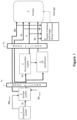
- FIG. 1 illustrates the flow of data in an exemplary image generation and display system, which incorporates the merged image generation and display technology and features of the presently disclosed technologies not according to the invention and present for illustration purposes only. It should be understood that, while FIG. 1 illustrates a particular embodiment of a flow diagram with certain processes taking place in a particular serial order or in parallel, various other embodiments of the presently disclosed technologies are not limited to the performance of the image processing steps in any particular order, unless so specified.
- the image generation and display system includes an image acquisition system 1 that acquires tomosynthesis image data for generating Tp images of a patient's breasts, using the respective three dimensional and/or tomosynthesis acquisition methods of any of the currently available systems.
- Mp images may also be generated.
- Some dedicated tomosynthesis systems or combined tomosynthesis/ mammography systems may be adapted to accept and store legacy mammogram images, (indicated by a dashed line and legend Mplegacy in FIG. 1 ) in a storage device 2, which is preferably a DICOM-compliant Picture Archiving and Communication System (PACS) storage device.
- PPS Picture Archiving and Communication System
- the Tp images are transmitted from either the acquisition system 1, or from the storage device 2, or both, to a computer system configured as a reconstruction engine 3 that reconstructs the Tp images into reconstructed image "slabs" Tr, representing breast slices of selected thickness and at selected orientations, as disclosed in the above mentioned patents and application publication.
- the imaging and display system 1 further includes a 2D synthesizer that operates substantially in parallel with the reconstruction engine for generating 2D images that simulate mammograms taken at any orientation (e.g., CC or MLO) using a combination of one or more Tp and/or Tr images.
- the synthesized 2D images may be generated dynamically prior to display (as shown in FIG. 1 ) or may be stored in storage system 2 for later use.
- the synthesized 2D images are interchangeably referenced as T2d and Ms.
- the reconstruction engine 3 and 2D synthesizer are preferably connected to a display system 5 via a fast transmission link.
- the originally acquired Mp and/or Tp images may also be forwarded to the display system 5 for concurrent or toggled viewing with the respective Tr and/or Ms images by a medical professional.
- Mode filters 7a, 7b are disposed between image acquisition and image display.
- Each of the filters 7a and 7b may additionally include customized filters for each type of image (i.e., Tp, Mp, Tr) arranged to identify and highlight certain aspects of the respective image types.
- each imaging mode can be tuned or configured in an optimal way for a specific purpose.
- the tuning or configuration may be automatic, based on the type of the image, or may be defined by manual input, for example through a user interface coupled to a display. In the illustrated embodiment of FIG.
- the filters 7a and 7b are selected to highlight particular characteristics of the images that are best displayed in the respective imaging mode, for example, geared towards highlighting masses or calcifications, or for making the merged image (described below) appear to be a particular image type, such as a 3D reconstructed slice, or a 2D mammogram.
- the system 1 includes an image merge processor 6 that merges relevant image data obtained from a set of available source and synthesized images of a patient's breast to provide a merged 2D image IMERGE for display.
- the set of available images used to generate the merged image IMERGE may include filtered and/or unfiltered Ms, Mp, Tr and/or Tp images. While FIG. 1 depicts all these types of images being input into the image merge processor 6, it is also envisioned within the scope of the disclosed technologies that the merged mage may be manually configurable. For example, a user interface or preset configuration may be provided and configured to allow a user to select a particular group of two or more images or image types for generating a synthesized 2D image IMERGE for display.
- a medical professional such as a radiologist, may wish to merge two or more reconstructed tomosynthesis slices (or slabs) in order to provide a merged image showing the most readily discerned structures in the collective tomosynthesis image data in a displayed synthesized 2D image, which essentially maps the tomosynthesis slices (or slabs) at a pixel wise granularity.
- the radiologist may combine a 2D mammogram image, whether Mp or Ms, with a 3D projection, or with selected reconstructed images, in order to obtain a customized merged image that highlights both calcifications and various tissue structures in the breast.
- Filters applied to each type of image can further highlight the types of structures or features in the merged image that are generally most prevalent or most readily discerned in the respective source image type.
- one type of filter may be applied to mammography images to highlight calcifications, while a different filter may be applied to tomosynthesis slices to highlight masses, allowing both the highlighted calcifications and highlighted tissue masses to be displayed in the single merged image.
- Filters may also provide the merged image with a desired look and feel; i.e., to make the merged image appear more like a tomosynthesis or mammography image.
- the display system 5 may be part of a standard acquisition workstation (e.g., of acquisition system 1), or of a standard (multi-display) review station that is physically remote from the acquisition system 1.
- a display connected via a communication network may be used, for example, a display of a personal computer or of a so-called tablet, smart phone or other hand-held device.
- the display 5 of the system is preferably able to display IMERGE, Ms, Mp and Tr (and/or Tp) images concurrently, e.g., in separate side-by-side monitors of a review workstation, although the technology may still be implemented with a single display monitor, by toggling between images.
- Tr slices are preferably reconstructed all to the same size for display, which can be the same as the size of an Mp or Ms image of the breast, or they can be initially reconstructed to sizes determined by the fan shape of the x ray beam used in the acquisition, and then later converted to that same size by appropriate interpolation and/or extrapolation. In this manner, images of different types and from different sources can be displayed in desirable size and resolution.
- an image can be displayed in (1) Fit To View Port mode, in which the size of the displayed image size is maximized such that the entire imaged breast tissue is visible, (2) True Size mode, in which a display pixel on the screen corresponds to a pixel of the image, or (3) Right Size mode, in which the size of a displayed image is adjusted so that it matches that of another image being concurrently displayed, or with which the displayed image is, or can be, toggled.
- the merged image IMERGE is automatically resized, accordingly.
- the system 1 which is described as for purposes of illustration and not limitation in this patent specification, is capable of receiving and displaying selectively tomosynthesis projection images Tp, tomosynthesis reconstruction images Tr, a synthesized mammogram image Ms, and/or mammogram (including contrast mammogram) images Mp, or any one or sub combination of these image types.
- the system 1 employs software to convert (i.e., reconstruct) tomosynthesis images Tp into images Tr, software for synthesizing mammogram images Ms, and software for merging a set of images to provide a merged image that displays, for every region of the merged image, the most relevant feature in that region among all images in the source image set.
- an object of interest or feature in a source image may be considered a 'most relevant' feature for inclusion in the merged image based upon the application of one or more CAD algorithms to the collective source images, wherein the CAD algorithms assign numerical values, weights or thresholds, to pixels or regions of the respective source images based upon identified/detected objects and features of interest within the respective region or between features or, in instances when the merged image is generated directly from the synthesized image without CAD assistance, simply the pixel value, weight or other threshold associated with a pixel or region of the image.
- the objects and features of interest may include, for example, spiculated lesions, calcifications, and the like.
- FIG. 2 is a diagram not according to the invention and present for illustration purposes only which pictorially illustrates the merging of image data from a tomosynthesis reconstruction image data set Tr, comprising tomosynthesis slices 10A to 10N, with image data from a mammogram 20, in this case a synthesized mammogram Ms.
- Tr tomosynthesis reconstruction image data set
- Ms synthesized mammogram
- the tomosynthesis image data set Tr and synthesized mammogram Ms are forwarded to the region compare and image merge processor 6, which evaluates each of the source images for which a merged image is to be generated (i.e., whether automatically, or based on a specific user commend) in order to (1) identify the objects and features of interest in each image for those that may be considered a "most relevant" feature for possible inclusion in the merged image based upon the application of one or more CAD algorithms (as described above), (2) identifies respective pixel regions in the images that contain the identified features, and (3) thereafter compares the images on a region by region basis, searching for that image with the most desirable display data for each respective region.
- the region compare and image merge processor 6 evaluates each of the source images for which a merged image is to be generated (i.e., whether automatically, or based on a specific user commend) in order to (1) identify the objects and features of interest in each image for those that may be considered a "most relevant" feature for possible inclusion in the merged image based
- the image with the most desirable display data may be an image with a highest pixel value, a lowest pixel value, or which has been assigned a threshold value or weight based on the application of a CAD algorithm to the image.
- the pixels of that region are copied over, or added in with higher weight, to the corresponding region of the merged image. For example, as shown in FIG. 2 , region 36M from image Ms is written to region 361. Region 35 of tomosynthesis slice 10A is copied to region 351 of the merged image.
- the regions of FIG. 2 are shown as pre-defined grid regions, it is not necessary that regions be pre-defined in this manner.
- FIG. 3 illustrates a merged image 50, which has been constructed via the combinations of numerous regions of different source images, at arbitrary region boundaries, for example, which may be identified according to the detection of particular features within the respective source images.
- FIG. 4 is a flow diagram not according to the invention and present for illustration purposes only provided to illustrate exemplary steps that may be performed in an image merge process carried out in accordance with one embodiment of the disclosed technologies.
- an image data set is acquired.
- the image data set may be acquired by a tomosynthesis acquisition system, a combination tomosynthesis/mammography system, or by retrieving pre-existing image data from a storage device, whether locally or remotely located relative to an image display device.
- a user may optionally select a merge mode, wherein the user may designate (1) which images are to be used for the source image set to generate the merged image, (2) whether to highlight certain features in the merged image, such as calcifications, spiculated lesions or masses, and (3) whether to display the image as a lower resolution tomosynthesis image, etc.
- the images that are to be merged to generate the merged image are mapped to a common coordinate system, for example, as described in U.S. Patent No. 7,702,142 . Other methods of matching images of different coordinate systems may alternatively be used.
- the process of comparing regions among the different images begins.
- each IMERGE region is populated with the pixels of the region of an image from the source image set having the most desirable pixels, value, or pattern. The process of populating regions continues until it is determined, at step 76, that all regions have been evaluated, at which point the merged image is ready for display.
- FIG. 5A and Fig. 5B illustrate two views of a display 80.
- the first view of display 80 shown in FIG. 5A illustrates a merged image 82, having regions sourced by different ones of an acquired or synthesized image set.
- FIG. 5B illustrates a particular feature enabled by the presently disclosed technologies, whereby a user may select a region or area 83 within the merged image 82, and the resulting image source 84 for that area is presented to the user.
- the presently disclosed technologies envision many different mechanisms for selection of the objects of interest and corresponding display of the respective source images corresponding; although it is to be understood that the disclosed technologies are not limited to those described herein.
- the selection of a region or area within the merged image may include a selection of a CAD mark, or alternatively a selection of a particular feature of interest to the reviewer.
- the most relevant slices are made available to the user, the mechanics behind the processes differ.
- FIG. 2 One such preferred mechanism is illustrated in FIG. 2 .
- a merge (or "guidance") map 40 is also constructed.
- the merge map stores, for each region of the merged image, an identifier of the image from which the region is sourced. Therefore, as shown in FIG.
- the Ms identifier is stored in region 36, while the 10A TR slice identifier is stored in region 35.
- the merged map may be used during the display of the merged image to permit fast viewing of the respective source image(s) for user-selected regions or objects of interest.
- the CAD overlay may include either CAD marks derived from 3D data, or CAD marks derived from 2D data (if the system has the ability to obtain 2D data).
- CAD marks derived from 3D data generally include, as part of the data object associated with the mark, identifiers of one or more slices which contributed to the generation of the 3D mark.
- selection of the CAD mark results in the retrieval of the series of slices that contributed to the mark.
- the central image slice is displayed; in alternate embodiments, the image slice having the highest weight is displayed; and in a still further alternate embodiment, the image slice having the least visual noise (i.e., the clearest image) is displayed.
- a mechanism not according to the invention and present for illustration purposes only is provided for allowing a user to select any object on a merged image, whether it is a CAD mark, or a feature of interest, such as any abnormality or irregularity in the image.
- the user or system may select a region, using for example a mouse click for a single pixel area, or a click and drag action to select a larger region.
- the user may be provided with a selection of graphical frames of various or variable sizes, and have the ability to move the frame to different locations within the merged image to select areas when it is desired to view additional tomosynthesis image slices.
- the particular image slice for initial display may be selected in a variety of ways.
- an image slice could be selected based on the weighting of its associated pixel within the selected region.
- a particular image slice may be selected because a particular feature which is selected, or which is near a pixel or region that is selected, is best viewed in the selected image slice, e.g., provides the clearest view of that region.
- the identification of a particular image slice that is most relevant to a selected pixel or region may utilize pixel information that surrounds the selected object, for example, using region growing techniques known to those in the art.
- pixels that neighbor the selected pixel or region are included in the evaluation for relevant slices if the pixels have a characteristic that satisfies a certain threshold established by the user; for example, including but not limited to the pixels having a particular weight, or being arranged in a particular pattern, etc.
- a group of image slices may be selected, e.g., a successive order of image slices, with a central slice or most heavily weighted slice being first presented.
- the image slice within the group having the least noise i.e., the clearest slice.
- the selection of an image slice for presentation may also take into account a desired visualization mode. Thus, if the user-specified purpose is to visualize calcifications, an image slice having calcification features may be presented ahead of another slice within the group having a lesser calcification characteristic.
- the synthesized 2D merged image can act as a guidance-map, so that the medical professional reviewing the images can focus on the synthesized 2D image for detecting any objects or regions of interest that merit further review, and the system can provide immediate, automated navigation to a "best" corresponding tomosynthesis image slice (or a subset of adjacent tomosynthesis slices) to allow the medical professional to conduct this further review, verify and evaluate the finding.
- the medical professional it is preferred, although not required for practicing all embodiments of the disclosed technologies, for the medical professional to employ a user interface that can display a respective synthesized 2D merged image along-side the tomosynthesis volume image slices, for concurrent viewing of both.
- FIG. 6 illustrates one exemplary process 180 not according to the invention and present for illustration purposes only for retrieving and presenting a Tr image slice in response to user-selection of an object of interest in a merged image, which may be implemented using a software program according to one embodiment of the presently disclosed technologies.
- the process 180 operates, in response to a selection of an object of interest in a merged image at step 182.
- the process determines whether the selected object is a CAD mark or a non-CAD mark feature of interest. If it is a CAD mark, at step 185, the Tr slices related to the CAD mark are retrieved.
- one of the Tr slices is selected and presented for display based on at least one of its relative position in the stack, relative weight of the voxel value of the slice, a selected visualization mode, etc. If, at step 184, the process determines that the selected object was a non-CAD mark feature of interest, then at step 186, the source Tr images associated with the selected region are evaluated, and a particular Tr source is selected for display based on its relative voxel value as compared to voxel values in other Tr sources that map to the region. It is noted that the Tr sources that contribute to pixel values within a selected region may be intermittently spaced within the 3D tomosynthesis volume.
- the most relevant Tr source image when selected, it may be presented either alone, or as part of a stack of images together with one or more neighboring Tr slice images.
- the most relevant Tr source may be the presented image, or alternatively another image in the stack associated with the most relevant image may be first presented, for example if that particular image is clearer.
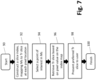
- FIG. 7 depicts another process not according to the invention and present for illustration purposes only that may be software-implemented for using a synthesized 2D image for navigating a 3D tomosynthesis image stack ("tomosynthesis stack" or "tomo stack”), according to another embodiment of the presently disclosed technologies.
- the process includes, at step 92, constructing a tomosynthesis image slice index map, wherein the pixel locations of the synthesized 2D image are mapped to corresponding pixel locations in pertinent image slices of the tomosynthesis stack.
- the tomosynthesis stack index map includes identifying information of selected tomosynthesis slice images from the breast volume stack that are source images or that otherwise contain a most similar representation of regions and/or objects displayed in the synthesized 2D image.
- the tomosynthesis stack index map is preferably generated prior to when a medical professional is ready to conduct his or her review of the breast image data.
- the synthesized 2D image is displayed to the medical professional (interchangeably referred to as the "user" of the described system), typically on a workstation having side-by- side monitors as depicted in FIGS. 9-11 .
- the medical professional interchangeably referred to as the "user" of the described system
- the workstation having side-by- side monitors as depicted in FIGS. 9-11 .
- only the synthesized 2D image may be presented, e.g., on the left-hand-side monitor, with the right- hand-side monitor being blank, or perhaps depicting a first or middle image slice from the tomosynthesis stack, preferably depending on a user-selectable configuration.
- the system will initially display the synthesized 2D image on the left-hand-side monitor, and a "most relevant" one of the tomosynthesis slice images on the right-hand-side monitor, which was determined by the system based upon the displayed tomosynthesis slice being most similar in appearance to the synthesized 2D image, or having the relatively most interesting objects, out of the tomosynthesis image stack for the entire breast volume.
- the medical professional may use the user-interface to activate the navigational capability of the system.
- the user may affirmatively input a command to select a particular object or region in the displayed synthesized 2D image.
- the system may be configured so that the user merely positions a "pointer,” e.g., a movable cross or arrowhead that is controlled using a mouse or similar input device), overlying an object or region in the displayed synthesized 2D image, thereby "indicating" an interest in the item.
- the system may easily retrieve, at step 96, and display on the right-hand-side monitor, at step 98, the tomosynthesis slice that is either the direct source of the user selected/indicated object or region, or which otherwise contains a most similar representation of the object or region as depicted in the displayed 2D image. Additionally and/or alternatively, the system may be configured for concurrently displaying a respective source image and/or most similar representation of a tissue structure or region that corresponds to a given location of a user movable input device in the displayed synthesized 2D image.
- the plurality of 2D and/or 3D images from which a synthesized 2D image is generated may include tomosynthesis projection images, tomosynthesis reconstruction slices, mammography images, contrast enhanced mammography images, synthesized 2D images, and combinations thereof.
- the synthesized 2D image advantageously incorporates the most relevant information from each of the underlying acquired and computer generated image data sets of the patient's breast.
- different regions of pixels in the displayed synthesized 2D image may be sourced from corresponding different images in the underlying image data set, depending on which underlying image is best for viewing an object of interest, e.g., a mass or a calcification, in the respective region.
- the particular regions may be identified statically, i.e., within a particular grid, or dynamically, i.e., based on identified objects of interest, and may range in granularity from as little as one pixel, to all pixels in the respective image.
- priority is given to first importing into a merged image under construction those regions containing one or more specific tissue structures of interest in the images of a tomosynthesis image data set (or "stack"), and thereafter populating the remaining regions of the merged image with the otherwise most relevant regions from the images, as described above.
- the user interface may additionally include features to enable the medical professional to manipulate the presented tomosynthesis data, for example, to allow the medical professional to scan through adjacent image slices of the tomosynthesis stack, or to further zoom (magnify) into a selected region, to place markers, or alternatively to apply filters or other image processing techniques to the image data.
- the medical professional may quickly review a large stack of tomosynthesis data by utilizing a synthesized 2D image for navigation purposes, thereby increasing the performance and efficiency of breast cancer screening and diagnosis.
- particular types of images may include or be superior for viewing different types of relevant information. For example, calcifications are typically best visualized in 2D mammograms, while masses are typically best visualized using 3D reconstructed images.
- different filters are applied to each of the different types of underlying 2D and/or 3D images in the image data set used to generate the merged image, the filters selected to highlight particular characteristics of the images that are best displayed in the respective imaging mode.
- Appropriate filtering of the images prior to generating the merged image helps ensure that the final merged image includes the most relevant information that can be obtained from all the underlying image types.
- the type of filtering performed for the various images may be defined via user input, which permits a user to select a 'merge mode', for example, geared towards highlighting masses, calcifications, or for making the merged image appear to be a particular image type, such as a 3D reconstructed slice, or a 2D mammogram.
- Synthesizing the 2D image may be accomplished in a variety of ways. For example, in one embodiment, general purpose image filtering algorithms are used to identify features within each of the respective 2D and 3D images, and a user may select whether to use 2D filtered data or 3D filtered data to generate the merged image. Alternatively, 2D or 3D filtered data may be automatically selected in accordance with a particular visualization mode that has been user selected; for example, 2D filtered data may be automatically selected by the system for calcification visualization mode, while 3D filtered data may be automatically selected by the system for mass visualization modes. In one embodiment, two different merged images may be constructed, one for each mode; alternatively, a single merged image may be constructed that takes into account the respective filtered image data results from all available image types.
- features are identified in the available source images and thereafter weighted, e.g., on a pixel by pixel or region by region basis in each respective image.
- a 2D image is then constructed by incorporating the respective regions having the most significant weight in individual images of the available source images.
- the size of the region may vary in granularity from one pixel to many (or even all) pixels of the respective image, and may be statically pre-defined, or may have margins that vary in accordance with the varying thresholds of the source images.
- the synthesized (aka "merged") image may be pre-processed and stored as a DICOM object following tomosynthesis acquisition, and thereafter forwarded with the reconstruction data for subsequent review by a medical professional.
- the stored DICOM object may include the weighting information, allowing the merged image to be dynamically constructed in response to a request for a synthesized 2D image at the medical professional's work station.
- both the weighting information and the synthesized 2D image may be provided in the DICOM object, allowing presentation of a default merged image, while still enabling customization according to the personal workflow of the reviewer.
- the weighting information can be stored with the image itself, and need not be a separate file.
- the visualization of the synthesized 2D images may have some drawbacks. For example, there may be neighboring regions in the merged image which exhibit bright calcifications, but which in fact are sourced from image slices that are distant from one another in the z plane. Therefore, what may appear to be a cluster of micro- calcifications in the 2D image may, in fact, be individual calcifications that are distributed (i.e., along the z-axis) throughout the breast and thus do not actually represent a micro-calcification cluster that requires further review.
- a 'cluster spread indicator' may be provided with the synthesized 2D image, which visually indicates the distribution of calcifications along the z-plane, allowing the medical professional to quickly assess whether a group of calcifications comprise a calcification cluster.
- the system may determine based on the index map information that more than one tomosynthesis image slice should be displayed for a selected/indicated object type or region, for example, a spiculated mass. In such instances, a series of two or more adjacent tomosynthesis slices are displayed, one after the other, at a timing interval that is preferably user selected. As will be additionally described herein, the user may select or indicate more than one object or region in a given synthesized 2D image.
- the system is preferably configured for, and the method further includes, generating an index map comprising identifying information of selected images of the plurality of 2D and/or 3D images that are source images or that otherwise contain a most similar representation of regions and/or objects displayed in the synthesized 2D image.
- the index map can thereafter be used by the system to greatly reduce the time needed to navigate through the images, e.g., a tomosynthesis volume stack of the breast image volume.
- the image data contained in the synthesized 2D image 104 is mapped to selected tomosynthesis image slices of a 3D volume 106 to construct a "generic" index map 108.
- the pixel locations in the 2D image 104 is mapped to the pixel locations in the respective 3D (tomosynthesis) images 106 based entirely on image similarity, akin to the pieces of a jigsaw puzzle.
- the generic index map 108 is based entirely on best-fit matching of the appearance of the data in the 2D image to the appearance of the data in the respective 3D images, wherein the slice identification and X,Y coordinates of a 3D image having a most similarly appearing pixel region to a corresponding X,Y region in the 2D region is selected. Potential importance of the respective objects and features in the synthesized 2D image is not taken into account for constructing the generic index map 108.
- an object type index map 114 is generated, in which individual object types, designated as 110-1 to 110-n in FIG. 8 , in the synthesized 2D image are prioritized and assigned weighted values to influence the selection of the best corresponding 3D tomosynthesis image slice.
- an individual object type index map, designated as 112-1 to 112-n in FIG. 8 is generated for each object type identified in the synthesized 2D image, e.g., blob density, spiculated masses, micro-calcifications, etc.
- the individual object type index maps 112-1 to 112-n are then combined to construct the full object type index map 114, which is then blended, at step 116, with the generic index map 108 to provide a composite index map 120, wherein the object type image data is prioritized relative to the generic image data.
- the composite index map 120 is then used by the system for navigating the image slices of the 3D volume 106 in response to a selected or indicated location on the 2D image 104. In this manner, different object types having overlapping X,Y coordinates, i.e., due to their location at different z-axis positions in the volumetric breast image, can nevertheless be separately navigated for selective viewing, since separate mapping indexes are provided (See below example with respect to FIGS. 10 and 11 ).
- an object or region may be automatically highlighted in the synthesized 2D image and/or displayed at least portion of the one or more images from the plurality. Additionally and/or alternatively, an object or region in the synthesized 2D image and/or displayed at least portion of the one or more images from the plurality may be highlighted in response to a further received user command or to certain user activity detected through the user interface.
- an object or region may is highlighted by a contour line representing a boundary of the highlighted object or region.
- the object or region is highlighted in a manner indicating that the highlighted object or region is or contains a specified type of tissue structure.
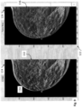
- FIG. 9 depicts an exemplary work station display 122, including a left-hand side monitor 124 ("C-View") displaying a synthesized 2D image 132 of a patient's breast.
- the synthesized 2D image 132 includes a highlighted tissue structure 134, wherein the highlighting is in the form of a contour line that represents a boundary of the tissue structure.
- this highlighting may have been done automatically by the system, e.g., at the time the 2D image 132 is initially displayed, or only in response to a specific user command or indication, e.g., by hovering a pointer over the object 134 in the 2D image 132.
- the work station display 122 also includes a right-hand side monitor 126 displaying the respective tomosynthesis image 136 (which is slice no. 18 of the tomosynthesis volume stack, as indicated in the lower right hand side of the monitor 126), which is the source image or which otherwise provides a most similar view of the highlighted tissue structure 134 as seen in the synthesized image 132.
- a right-hand side monitor 126 displaying the respective tomosynthesis image 136 (which is slice no. 18 of the tomosynthesis volume stack, as indicated in the lower right hand side of the monitor 126), which is the source image or which otherwise provides a most similar view of the highlighted tissue structure 134 as seen in the synthesized image 132.
- the user interface associated with the display 122 allows for a user to select or otherwise indicate a location on the synthesized 2D image 132, e.g., by displaying a pointer, a cross, a circle, or other similar geometrical object, and then input a certain command type (e.g., mouse click) that will be recognized by the system as a request from the user to have the corresponding source or otherwise most similar tomosynthesis slice(s) depicting the region or object underlying the pointer displayed in monitor 126.
- a certain command type e.g., mouse click
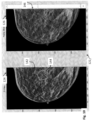
- FIG. 10 depicts the work station display 122, wherein a different synthesized 2D breast image 142 is displayed in the left-hand side C-View monitor 124.
- the synthesized 2D image 142 includes a highlighted tissue structure 144, wherein the highlighting is in the form of a geometric shape, in this case a circle, to indicate that the object 144 is a spiculated mass.
- this highlighting may have been done automatically by the system, e.g., at the time the 2D image 142 is initially displayed, or only in response to a specific user command or indication, e.g., by hovering a pointer over the object 144 in the 2D image 142.
- the right- hand side monitor 126 is displaying the respective tomosynthesis image 146 (which is slice no. 33 of the tomosynthesis volume stack, as indicated in the lower right hand side of the monitor 126), which is the source image or which otherwise provides a most similar view of the highlighted tissue structure 144 as seen in the synthesized image 132.
- FIG. 11 depicts the user work station display 122, including the same synthesized 2D breast image 142 as displayed in FIG. 10 , but now highlighting a region 154 containing micro-calcifications, with the right-hand side monitor displaying the tomosynthesis image slice 156 (which is slice no.
- the system may execute an algorithm to automatically compute the best corresponding image (i.e., X,Y and Z) within the tomosynthesis stack for display on the right-hand-side monitor 126.
- a "tomosynthesis slice indicator" may optionally be provided on the left-hand-side monitor 124, which indicates which tomosynthesis slice number (numbers) would be displayed on the right-hand-side monitor 126 based on a current location of a user curser on the 2D image.
- the available features of the user interface may be extended to function, not only based point/location of the merged image, but also based in a similar fashion on a structure/object/region.
- particular objects or region(s) in the merged image may be automatically highlighted when displayed, based on the system recognition of possible interest in the respective objects, or of objects located in the respective region(s).
- this highlighting is in the form of a contour line 108 that represents a boundary of a highlighted tissue structure.
- a contour line may be similarly used to highlight regions of interest in the displayed image, e.g., containing a number of calcification structures.
- the system is configured to allow the user to "draw" a contour line on the merged image as a way of selecting or otherwise indicating an object or region of interest for causing the system to concurrently display one or more underlying source images of the selected or indicated object or region.
- the system employs known image processing techniques to identify different breast tissue structures in the various source images, and highlight them in the merged image, in particular, tissue structures comprising or related to abnormal objects, such as micro-calcification clusters, round-or-lobulated masses, spiculated masses, architectural distortions, etc.; as well as benign tissue structures comprising or related to normal breast tissues, such as linear tissues, cysts, lymph nodes, blood vessels, etc.
- tissue structures comprising or related to abnormal objects, such as micro-calcification clusters, round-or-lobulated masses, spiculated masses, architectural distortions, etc.
- benign tissue structures comprising or related to normal breast tissues, such as linear tissues, cysts, lymph nodes, blood vessels, etc.
- an object or region consisting of or containing a first type of tissue structure may be highlighted in a first manner in the displayed merged image, and an object or region consisting or containing a second type of tissue structure may be highlighted in a second manner different from the first manner in the displayed merged image.
- the user may input a command through the user interface selecting or otherwise identifying a certain type of tissue structure, and, in response to the received command, the system performs one or both of (i) automatically highlighting in the displayed merged image objects comprising the selected type of tissue structure and/or regions containing one or more objects comprising the selected type of tissue structure, and (ii) automatically concurrently displaying the respective source slice (or otherwise the slice with best depiction of) a tissue structure of the selected type in the breast image data, e.g., a most prominent one of the selected tissue structure type based on a comparison, if more than one is detected in the source image stack.
- the system automatically concurrently displays the source (or otherwise best) tomosynthesis image slice including the corresponding micro-calcification in 3D.
- a user can select (through the user interface) a region in the 2D merged image that has the appearance with radiating line patterns (often an indication of spiculated masses), and the system will concurrently display the source (or otherwise best) 3D tomosynthesis slice, or perhaps to a series of consecutive tomosynthesis slices, for viewing the radiating line patterns.
- the user may input a command through the user interface, activating dynamic display functionality, wherein the system automatically highlights those objects and tissue structures that (dynamically) correspond to the location of a user movable input device in the displayed merged image.
- the system may further comprise automatically concurrently displaying a respective source image of a highlighted selected tissue structure that corresponds to a given location of a user movable input device in the displayed merged image, again, on a dynamic basis.
- the system can be activated to provide a "shadow" cursor is displayed on the right-hand-side monitor 126, in a location corresponding to the same (x,y) location as the user's actual curser on the left-hand-side monitor 124, so that moving the curser around in the 2D image moves the shadow curser in the tomosynthesis image at same X,Y coordinates.
- the reverse can also be implemented, i.e., with the active user curser operable in the right-hand monitor 126, and the show curser in the left-hand monitor 124.
- this dynamic display feature allows the system to follow the user's point of interest, e.g.
- mouse cursor location in the 2d merged image, and dynamically display/highlight the most "meaningful" region(s) underneath in real time. For example, the user can move the mouse (without clicking any button) over a blood vessel, and the system will instantly highlight the vessel contour.
- the mapping concepts described herein may be extended to generate a fully mapped 3D volume, with each of the voxels in the mapped volume storing information related to the associated tomosynthesis slices(s) sourcing the particular voxel.
- the volume may be projected onto a fixed coordinate system, regardless of the actual volume of the breast. Projecting the volume to a fixed coordinate system in this manner facilitates processing of the image data, in particular, simplifying the correlation of voxels obtained during different acquisitions.
- one or more 3D maps may be provided, for example, to map from voxels in one slice of a 3D volume acquired via CC to one or more corresponding voxels in another volume, for example acquired via an MLO view.
- Such an arrangement facilitates comparison of slices obtained from different acquisitions that relate to a similar feature of interest within the breast volume, essentially permitting the medical professional to obtain a multi-planar review of a region of interest.
- a multi-mode mammography/tomosynthesis system may be generally used as follows.
- a patient who has been identified as a candidate for biopsy is positioned at the multi-mode x-ray imaging system.
- the biopsy compression paddle moves down towards the compression platform, compressing the patient's breast, and the process of visualizing the lesion is initiated at step 162.
- visualization of the lesion can be performed utilizing a synthesized mammogram, in accordance with the embodiments described herein.
- Such an embodiment likely includes the lesion to be biopsied, unlike a first image presented in a stack of Tr images (alternatively referred to herein as tomo stack) commonly.
- the synthesized mammogram better emulates the images that a doctor sees during traditional stereotactic biopsy. Using this mode may also save time scrolling through a tomo stack, since the synthesized mammogram optionally derives data from the tomo stack.
- tomosynthesis mode can be used for a scout acquisition while still presenting the synthesized mammogram to a user in an effort to identify the relevant slice in the tomo stack in which the lesion is presented.
- visualization of the lesion may optionally use a scout image, a mammogram, acquired stereotactic images, acquired tomosynthesis projection images, tomosynthesis reconstructed images, or any combination thereof.
- an x-ray imaging system having tomosynthesis capabilities may be adapted to include a "stereotactic mode," which, when selected, causes the x-ray imaging system to automatically retrieve the typical +/-15 degree stereotactic images and performs appropriate imaging processing on the stereotactic images to derive a stereotactic volume.
- a stereotactic mode which, when selected, causes the x-ray imaging system to automatically retrieve the typical +/-15 degree stereotactic images and performs appropriate imaging processing on the stereotactic images to derive a stereotactic volume.
- the lesion is targeted, either using the synthesized mammogram and/or the slice in the tomo stack to which the user is directed from the synthesized mammogram.
- Targeting the lesion may involve identifying the coordinates of the lesion using image data, and optionally converting the coordinates from the coordinate system of the images (e.g., a Cartesian coordinate system) to the coordinate system of the biopsy assembly using conversion techniques known to those of skill in the art.
- different images, or combinations of images may be used for visualizing the lesion than are used for targeting the lesion.
- composite images such as those described below with regard to FIG. 19 can be utilized for visualizing or targeting the lesion.
- a scout image is initially used to ensure that the patient is in position, a pair of stereotactic images is used to visualize the lesion. If the lesion is found in the scout image, but not in both stereo images, the scout image may be used in combination with the stereotactic image in which the lesion is located to derive target location information.
- the lesion target coordinates may be derived using a scout image, a mammogram, a synthesized mammogram, acquired stereotactic images, acquired tomosynthesis projection images, tomosynthesis reconstructed images, or any combination thereof.
- FIG. 13 illustrates an exemplary display and buttons of a control unit.
- the control unit includes a display 172 for displaying information related to the biopsy, such as information regarding needle size, distance to platform and paddle, needle coordinates, target coordinates, proximity to target and other related information.
- the control panel may also provide other helpful information to the user, such as warning indicators when the needle is too close to the breast platform, chest wall or skin line.
- the warning indicators may be color coded or may provide other visual or audible indicators of undesirable conditions.
- control unit also includes buttons (including button 170) positioned and arranged to allow single handed activation of the biopsy assembly while precluding accidental activation.
- buttons including button 170
- a pair of control buttons is provided, one on the front face of the control panel, and another on the back face of the control panel. Biopsy assembly movement may only be activated via simultaneous depression of both buttons. Other mechanisms for affirming operator intent may be substituted herein without affecting the scope of the technology.
- an image may be acquired to verify that, in fact, the needle is positioned at the lesion. If the biopsy needle is out of the view of the x-ray imaging system, such as that described in U.S. Patent Application Publication No. 2011/0087132 , such image may be obtained without interference.
- the tissue may be excised, and the biopsy is complete.
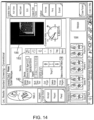
- FIG. 14 An example of user interface features that may be added to an acquisition workstation for use with a biopsy assembly is shown in FIG. 14 .
- the user interface includes menus and/or control buttons or icons which enable the user to control the display and output of information gathered during the biopsy.
- Targeting tools 180 allow the user to review, modify and delete target information.
- Image source selectors 182 (including stereotactic, tomosynthesis, scout, mammography, etc.) allow the user to select which images to use for visualization or targeting.
- Image view selectors 184 allow the user to quickly pull up and view any of the images that may have been acquired during the biopsy. Any of the images may be pulled up in the image window 186.
- buttons and icons may also be included on the acquisition workstation.
- Other information related to the biopsy such as the type of biopsy device, the relative distances between the target and the compression plate/platform, etc., may also be included on the acquisition workstation.
- buttons and icons may also be included on the acquisition workstation.
- the present technology is not limited to any particular representation of such information, and other forms of pull down menus, hyperlinks, icons, buttons, and windows are considered equivalents hereto.
- the user interface may optionally include a biopsy window 200 overlaid on the synthesized mammogram.
- a biopsy window 200 overlaid on the synthesized mammogram.
- the biopsy window can optionally be toggled off and on by a user.
- the biopsy window can additionally or alternatively include an indication to the user if no calcium or mass is presented within the window.
- Such indication can be in the form of, but not limited to, an auditory or visual indication.
- determination of whether or not such an indication should be provided to the user is based at least in part on whether the biopsy window on the synthesized mammogram includes one of the features of the IMERGE map.
- presenting the synthesized mammogram to the user also facilitates navigating to a slice in the tomo stack in which the lesion or feature (e.g., abnormality, calcification, mass, etc.) is found.
- the lesion or feature e.g., abnormality, calcification, mass, etc.
- the user can be directed to the slice in the tomo stack that best presents the lesion or feature in the synthesized mammogram.
- the user interface can be configured such that the user can be directed to a slice just above or below the slice in the tomo stack that presents the lesion or feature, which can be useful since a user may scroll through the tomo stack to be presented with varying views of the lesion or feature.
- a visual target or indication can be placed automatically on the slice of interest in the tomo stack in response to a user selecting a lesion or feature on the synthesized mammogram presented to the user.
- a user can be directed to the lesion or feature on the relevant slice to correct the target for biopsy, e.g., by jogging in the X- or Y-directions or nudging in the Z-direction, if necessary.
- targets placed on the relevant slice can also be automatically placed or selected through use of CAD of calcification or mass enhancement in the synthesized mammogram. This could help with biopsy workflow as such selected targets or placements could be considered biopsy targets, which when used in combination with the biopsy window can ensure proper patient positioning.
- Such targets or placements can be independently verified by jumping to or scrolling through the slice(s) in the tomo stack.
- Image-guided biopsies in accordance with an embodiment of the technology may include use of one or more modes of contrast imaging, dual energy imaging, and/or high energy imaging, all in either 2D or 3D images.
- dual energy imaging multiple x-ray images are acquired - of one at low x-ray energy and one at high x-ray energy.
- Various aspects of x-ray energy may be varied such as dose, intensity, wavelength, and/or other aspects of x-ray energy known to those of skill in the art.
- the dual energy image may be a linear combination of the image pairs.
- the dual energy image can be the difference between the high energy image and the low energy image.
- contrast imaging a contrast agent can be visualized in the high energy image alone, which can optionally take the place and serve the same function as the dual energy image.
- reference to a contrast image can refer to either a dual energy image or a high energy image in which a contrast agent can be visualized.
- Contrast images can be either 2D or 3D or even synthesized 2D images, e.g., in which the contrast synthesized 2D image is derived from contrast 3D images and/or dual energy 3D image.
- Nonlimiting examples of such imaging systems are described at least at U.S. Patent Application Publication No. 2012/0238870 .
- a breast imaging system combines the capabilities of combined 2D and/or 3D breast x-ray imaging with benefits from contrast image acquisition processes.
- Biopsy capability (stereotactic or tomosynthesis guided) may also be integrated into the system, with lesion localization software (e.g., such as those described herein) utilizing any images selected from a group including 2D images (e.g., Mp), synthesized 2D images, 3D projection images, 3D reconstructed data.
- images utilized may be selected from the group including any of the 2D (including synthesized 2D), 3D projection and 3D reconstructed data that were obtained utilizing a contrast, dual energy and/or background subtraction image acquisition process.
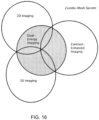
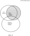
- Contrast imaging using a single high or low energy image acquisition technique, in 2D or 3D mode; Dual-energy contrast imaging in 2D or 3D mode; Dual-energy contrast imaging in 3D mode, wherein high and low energy exposures occur at different angles during a tomosynthesis scan; high and low energies can be reconstructed separately and combined to form the dual energy volume; Dual-energy imaging in a combo system that acquires dual-energy 2D and dual-energy 3D images; In combo imaging mode, where the 2D image data set is acquired using a single energy, and the 3D image data set is acquired using dual-energy imaging; In combo imaging mode, where the 2D image data set is acquired using dual-energy imaging, and the 3D image data set is acquired using a single energy image; In combo imaging mode, where the 2D image data set is acquired using dual-energy imaging, and the 3D image data set is acquired using a single energy image; Tomosynthesis imaging mode, wherein among a total of N views in a tomo scan, wherein the breast remains in compression throughout the scan,
- FIG. 16 illustrates a scope of imaging in different modes of operation of a combo system that operates in either or both of a 2D imaging mammography mode and a 3D imaging tomosynthesis mode.
- the system can image the breast with or without contrast agent in the breast.
- the system can carry out dual-energy imaging or background subtraction imaging.
- these capabilities allow for many different combinations of modes such as 2D using single-energy (SE) and contrast enhancement (CE), 2D using SE, 3D using CE, 3D using DE, etc.
- SE single-energy
- CE contrast enhancement
- FIG. 17 illustrates a scope of imaging when using a 2D only system, i.e., a system that does not include 3D tomosynthesis capabilities.
- the system can be used in single-energy or dual-energy modes, in each case with or without contrast agent in the breast.
- FIG. 18 illustrates the operation of a 3D only system that can operate in 3D imaging mode using single-energy or dual-energy imaging, in either case with or without contrast agent in the breast.
- a method of performing an x-ray contrast agent biopsy can comprise the following.
- a patient has an injection of the x-ray contrast agent.
- the patient is seated and given an IV injection of the contrast agent.
- a wait of typically 1-3 minutes occurs, which gives time for the contrast agent to accumulate in the breast tissue.
- the biopsy procedure using contrast agent can be similar to the non-contrast biopsy procedures that are well-known state of the art.
- the breast is compressed and one or more scout images are acquired to ensure that the lesion is appropriately centered in the biopsy paddle's opening. Unlike the non-contrast procedure, these scout images are dual-energy subtracted images, or in an embodiment not according to the invention and present for illustration purposes only high energy images, which visualize the contrast agent.
- the acquired images can be either 2D or 3D images.
- the displayed image can be 2D (including synthesized 2D) and/or 3D images.
- targeting commences. This is done with a stereo pair of (typically acquired at ⁇ 15°) dual energy images, or in an embodiment not according to the invention and present for illustration purposes only high energy 2D images, or in an embodiment not according to the invention and present for illustration purposes only one can target using the dual energy 3D scout image if that is available.
- a contrast biopsy procedure and system relate to the short time that the contrast agent is present and visible in the breast.
- the visibility of the contrast agent changes with time and the visibility can be reduced during the length of time of the biopsy. Therefore, a user interface and/or targeting features are provided in which one can identify the lesion in the contrast agent image and correlate it to a reference object visible in the non-contrast agent low energy, normal 3D image (Tp or Tr), 2D image and/or synthesized mammogram. This would facilitate post-fire verification imaging to occur after the visibility of the lesion in the contrast agent has disappeared. This will also allow biopsying of multiple sites when the contrast agent might only be visible during the initial parts of the biopsy of the first lesion.
- the display may be toggled to alternately show the low energy and the contrast image in the scout or stereo image pair.
- Coordinate crosshairs identified by the user may be saved in the contrast image and displayed on the low energy images.
- a crosshair may be located automatically on a standard tomo scout image and slice using crosshair locations or lesions identified by the user on the stereo contrast image.
- crosshairs may be automatically placed on stereo pairs (either low energy or contrast stereo pairs) from crosshairs or lesions identified on a tomo scout image that is either a standard low energy or a contrast scout image). Both the contrast image and the low energy image may be overlayed and/or simultaneously displayed on a single display, using different color maps for the two images.
- biopsies in accordance with the systems described herein include any one or more of the following: a system capable of performing stereo biopsy and contrast stereo biopsy; a system capable of performing tomo biopsy and contrast tomo biopsy; a system capable of performing stereo and tomo and contrast stereo and contrast tomo biopsy; biopsy systems that have as part of their user interface methods of toggling a display between a contrast and a low energy image; biopsy systems that have as part of their user interface methods of simultaneously superimposing and displaying a low energy and a contrast image; a system that allows marking crosshair locations in contrast images and displaying them on low energy images, to allow a biopsy procedure and verification to occur when the contrast agent is no longer visible on the image due to the time elapsed during the procedure; a procedure of performing a biopsy using x-ray contrast guided imaging; a prone biopsy system that utilizes two or more x-ray filters, e.g., one filter is used for the low energy image, and another filter for the high-energy image, the high energy filter preferably contains
- FIG. 19 depicts one method 300 of performing a procedure not according to the invention and present for illustration purposes only, such as a biopsy, on a breast of a patient.
- a procedure not according to the invention and present for illustration purposes only, such as a biopsy, on a breast of a patient.
- Other methods consistent with the disclosures herein are contemplated.
- the breast is compressed with a paddle of an imaging system, typically between the paddle and an associated platform.
- a contrast agent may be injected into the patient before or after compression of the breast, operation 304.
- the amount of time between injection and imaging can be as required or desired for a particular contrast agent, patient specifics, technician experience, etc.
- An initial imaging procedure is then performed, operation 306.
- the imaging operation can include imaging the breast a plurality of times at predetermined dosages, which may be the same, substantially the same, or different.
- the first dosage may be higher than a subsequent dosage, such that the contrast agent is readily visible in an image resulting from the first imaging procedure.
- Dual energy imaging may also utilize two different dosages. Each imaging procedure may generate a discrete image that may be stored or processed as described below.
- a composite image (e.g., a combination of the plurality of images, one such combination being a substitution of a first image from a second image) can be generated, operation 308.
- Any of the various images resulting from each imaging procedure, or the composite image, can be displayed to a user, operation 310, for further analysis or study. Differences in the plurality of images may be indicative of a region of interest, which may be identified on the displayed image.
- a spatial position of the region of interest within the breast may be correlated with a reference object in the image, or the coordinates of the region of interest may be stored, operation 312.
- the region of interest may be targeted for further procedures, such as a biopsy.
- an indicator may be located so as to mark a region of interest within the breast, operation 314. This indicator may be located by action of a user of the system (e.g., an operator touching a screen), or the system may automatically mark a region of interest to draw attention thereto.
- a biopsy needle may be positioned, operation 316. Positioning may be performed manually or automatically, based on the various types of information stored on the system. Once positioned as required or desired, a biopsy may be performed, operation 318. Thereafter, to confirm the region of interest was properly targeted, the breast may be imaged again, operation 320.
- Every maximum numerical limitation given throughout this specification includes every lower numerical limitation, as if such lower numerical limitations were expressly written herein. Every minimum numerical limitation given throughout this specification includes every higher numerical limitation, as if such higher numerical limitations were expressly written herein. Every numerical range given throughout this specification includes every narrower numerical range that falls within such broader numerical range, as if such narrower numerical ranges were all expressly written herein.
Description
- Mammography is a well-established method of breast imaging which may be used for breast cancer screening and diagnosis. Screening mammograms are preferably obtained annually for female members of the population over the age of forty, or those having a genetic risk of breast cancer. Should masses or calcifications ('regions of interest') be identified during a screening mammogram, the patient may require further diagnosis. Such diagnosis may involve biopsying the region of interest and analyzing excised tissue. As used herein, the term "region of interest" can mean a mass or calcification, or a specific area or target within the breast that may contain such a mass or calcification.
- Various imaging modalities have historically been used during breast biopsies. The imaging modalities include ultrasound imaging, x-ray imaging and magnetic resonance imaging. Performing a breast biopsy typically involves positioning the patient, visualizing the region of interest using the imaging equipment, targeting coordinates of the region and retrieving cells or tissue from the targeted region. Cells or tissue may be retrieved in a variety of ways, including through open surgery, fine needle aspiration, core needle biopsy or vacuum assisted biopsy. Open surgery, the most invasive procedure, is generally performed by a radiologist placing a wire into the breast during visualization of the region of interest, where the wire extends into the region that is to be excised. The patient is then transferred to surgery and tissue is retrieved using the wire to locate the region of interest.
- X-ray imaging in stereotactic mode is generally used for breast biopsies because it is desirable to visualize and target regions in a three dimensional volume. Stereotactic biopsies obtain volume information using x-ray images taken in at least two planes. The x-ray images are then processed to localize a target region of interest in three-dimensional space using the principal of parallax to determine the depth, or Z dimension, of the target region.
- Various approaches to breast biopsies with three dimensional imaging have included use of breast tomosynthesis. Nonlimiting examples of such approaches include
U.S. Patent Application Publication Nos. 2008/0045833 ,2011/0087132 , and2012/0238870 . Three-dimensional imaging is described generally inPCT Publication No. WO 2013/123091 . Although tomosynthesis-guided biopsy represents a simplified approach to targeting and imaging during biopsy procedures, the first image presented is typically a reconstructed slice within the tissue, either adjacent to the compression paddle or to the breast tray, and, thus, the lesion of interest may not necessarily be in view in the first image presented. Further examples of what is known in the state of the art include e.g.U.S. Patent Application Publication 2005/0084060 , which shows a CT image device using multiple energies to create composite images to be displayed. - Document
WO 2012/122399 A1 discloses systems and methods for x-ray imaging a patient's breast in combinations of dual-energy, single-energy, mammography and tomosynthesis modes that facilitate screening for and diagnosis of breast abnormalities, particularly breast abnormalities characterized by abnormal vascularity. - Pages 270-272 of Bushberg, Jerrold T., et al. The Essential Physics of Medical Imaging. 3rd ed., Lippincott Williams and Wilkins, 2011, disclose that in stereotactic breast biopsy the breast can be aligned and compressed by an open-area paddle and after verification with a scout image, two images of the breast can be acquired, at +15 and -15 degrees from the normal, causing the lesion projections to shift on the detector.
- What is needed, then, is an image guided biopsy approach that targets and presents the lesion reliably, accurately, and consistently, preferably, in the first image presented, similar to that of conventional stereotactic biopsy.
- The invention is set out in the appended set of claims.
- According to an aspect not according to the invention and present for illustration purposes only, targeting and biopsying of a lesion or feature of interest in a breast is facilitated by presenting a synthesized mammogram (e.g., for pre-verification, post-verification, or both) to a user in which the synthesized mammogram can be generated from 2D and/or 3D images (e.g., projection and/or reconstructed tomosynthesis images) of the breast. A biopsy window is optionally included in the user interface to indicate to a user whether the lesion or feature of interest has been correctly targeted. The lesion or feature of interest can be highlighted or featured in the synthesized mammogram. In such instances, a user can optionally select the lesion or feature of interest in the user interface and then the user can be taken to a relevant slice in the tomo stack (e.g., one the presents the lesion or feature of interest best or one that is right above or below the slice in the tomo stack that best presents the lesion or feature of interest. Optionally, an indication can be provided to the user if a lesion or feature of interest is not presented in the synthesized mammogram.
- Additionally or alternatively, according to the aspect not according to the invention and present for illustration purposes only, targeting and biopsying of a lesion or feature of interest in a breast is facilitated with a contrast agent in conjunction with or alternatively to dual energy imaging in which the imaging is 2D, 3D, or both. The contrast image, dual energy image, or high energy image is then presented to the user to target and commence biopsy of the lesion or feature of interest. In an embodiment, where the acquired images are 3D images (used with a contrast agent and/or dual energy), a synthesized mammogram can be presented to the user.
- In another aspect not according to the invention and present for illustration purposes only, the technology of performing a procedure on a breast of a patient, the method includes: compressing the breast of the patient with a paddle of an imaging system; performing an initial imaging procedure on the breast of the patient, wherein the initial imaging procedure includes imaging the breast with an x-ray source at a first energy to obtain a first image and a second energy to obtain a second image; generating a composite image from the first image and the second image; displaying the composite image; targeting a region of interest on the composite image; and performing a biopsy on a target location. In an embodiment, the method includes using information from the composite image to define the target location. In another embodiment, the method further includes, after performing the biopsy on the target location, imaging the breast with the x-ray source at a third energy to obtain a third image. In yet another embodiment, the method for targeting the region of interest includes: identifying the region of interest visible in the first image; and correlating the region of interest with a reference object visible in the second image. In still another embodiment, the method further includes locating an indicator proximate the region of interest on the composite image.
- In another embodiment of the above aspect not according to the invention and present for illustration purposes only, the method further includes storing coordinates of the region of interest. In an embodiment, the method further includes positioning a biopsy needle based at least in part on the stored coordinates. In another embodiment, the method includes injecting the patient with a contrast agent prior to imaging at the first energy, such that the contrast agent is visible in the first image. In yet another embodiment, the first energy is greater than the second energy. In still another embodiment, the composite image is at least one of a 2D image, a 3D image, and a synthesized 2D image.
- In another embodiment of the above aspect not according to the invention and present for illustration purposes only, the composite image includes a plurality of tomosynthesis images. In an embodiment, the method further includes simultaneously displaying the first image and the second image. In another embodiment, the method further includes displaying an overlay of the first image and the second image.
- In another aspect not according to the invention and present for illustration purposes only, the technology of performing a procedure on a breast of a patient, the method includes: compressing the breast of the patient with a paddle of an imaging system; imaging the breast with an x-ray source at a first energy to obtain a first image; imaging the breast with the x-ray source at a second energy to obtain a second image; identifying at least one difference between the first image and the second image, wherein the difference corresponds to a region of interest; and performing a biopsy on the region of interest. In an embodiment, the method includes: generating a composite image from the first image and the second image; displaying the composite image; and displaying the region of interest on the composite image. In another embodiment, the first energy is greater than the second energy. In yet another embodiment, the method further includes injecting the patient with a contrast agent prior to imaging the breast at the first energy. In still another embodiment, the method further includes, after performing the biopsy, imaging the breast with the x-ray source at a third energy to obtain a third image. In yet another embodiment, the method further includes displaying the third image.
- In another aspect not according to the invention and present for illustration purposes only, the technology relates to a method of performing a procedure on a breast of a patient, the method includes: compressing the breast of the patient with a paddle of an imaging system; delivering a plurality of x-ray energies to the breast from an x-ray source, so as to obtain a plurality of images; identifying at least one difference between the plurality of images, wherein the difference corresponds to a region of interest; displaying at least one image of the breast; identifying the region of interest on the displayed image; and performing a biopsy on the region of interest.
- Various aspects of at least one embodiment are discussed below with reference to the accompanying figures, which are not intended to be drawn to scale. The figures are included to provide illustration and a further understanding of the various aspects and embodiments, and are incorporated in and constitute a part of this specification, but are not intended as a definition of the limits of the technology. In the figures, each identical or nearly identical component that is illustrated in various figures is represented by a like numeral. For purposes of clarity, not every component may be labeled in every figure. In the figures:
-
FIG. 1 is a block diagram illustrating the flow of data through a system that includes a combination mammography/tomosynthesis acquisition system and/or a tomosynthesis-only acquisition system to acquire tomosynthesis and/or mammography (including contrast mammography) images of a patient's breast, and further includes one or more processors that implement the image merge technology of the presently disclosed technologies for providing a two dimensional synthesized image by importing the most relevant data from the acquired 2D and/or 3D source images into a single merged 2D image for display to a medical professional; -
FIG. 2 is a diagram illustrating the data flow of a series of tomosynthesis slices and a synthesized 2D mammogram through the image merge technology of the presently disclosed technologies to generate a merged image and a corresponding merge (or "guidance") map; -
FIG. 3 depicts one embodiment of a displayed merged image, wherein certain region boundaries are dynamically identified during merge image build; -
FIG. 4 is a flow diagram illustrating exemplary steps performed during an image merge process according to one embodiment of the presently disclosed technologies; -
FIGS. 5A and 5B illustrate one embodiment of a display of a merged image, and a resultant display of a source image in response to selection of a region in the merged image by a user; -
FIG. 6 is flow diagram illustrating an exemplary process for retrieving and presenting a reconstructed tomosynthesis image slice in response to user-selection of an object of interest in a synthesized 2D image, according to one embodiment of the presently disclosed technologies; -
FIG. 7 is a flow diagram illustrating another exemplary process for retrieving and presenting a reconstructed tomosynthesis image slice in response to user-selection of an object of interest in a synthesized 2D image, according to another embodiment of the presently disclosed technologies; -
FIG. 8 is a flow diagram illustrating a process for constructing a composite index map of a synthesized 2D image to a corresponding reconstructed tomosynthesis image stack, according to still another embodiment of the presently disclosed technologies; -
FIG. 9 depicts an exemplary user interface, including a left-hand side monitor displaying a synthesized 2D image of a patient's breast, including a highlighted tissue structure, wherein the highlighting is in the form of a contour line that represents a boundary of the highlighted tissue structure, and a right-hand side monitor displaying the tomosynthesis image from which the highlighted tissue structure was imported into the 2D image, or which otherwise provides a best view of the highlighted tissue structure; -
FIG. 10 depicts the user interface ofFIG. 9 , again displaying a synthesized 2D image of a patient's breast including a highlighted spiculated mass in the left-hand monitor, and a right-hand side monitor displaying the tomosynthesis image from which the depicted spiculated mass was imported into the 2D image, or which otherwise provides a best view of the spiculated mass; -
FIG. 11 depicts the user interface ofFIG. 10 , including the same breast image displayed in the left-hand side monitor, but now highlighting a region containing micro- calcifications, with the right-hand side monitor displaying the tomosynthesis image from which the highlighted region containing the micro-calcifications was imported into the 2D image, or which otherwise provides a best view of the micro-calcifications; -
FIG. 12 is a flow diagram illustrating exemplary steps that may be performed during a biopsy using the targeting and presentation systems of the present technology; -
FIG. 13 illustrates an exemplary view of a user interface of the control unit of an image-guided biopsy system of the present technology; -
FIG. 14 illustrates an exemplary view of a user interface of an acquisition work station including functional modules and displays supporting and related to an image-guided biopsy in accordance with an embodiment of the present technology; -
FIG. 15 illustrates an exemplary view of a portion of a user interface of an acquisition workstation related to an image-guided biopsy according to an embodiment of the present technology; -
FIG. 16 illustrates possible combinations of imaging modes of a system in accordance with an embodiment of the present technology; -
FIG. 17 illustrates possible combinations of imaging modes of a system according to an embodiment of the present technology, such as one that only takes 2D images; -
FIG. 18 illustrates possible combinations of imaging modes of a system in accordance with an embodiment of the present technology, such as one that only takes 3D images; and -
FIG. 19 depicts a method of performing a procedure on a breast of a patient. - Except as otherwise noted, the articles "a," "an," and "the" mean "one or more." While the existing and proposed systems for x-ray mammography and tomosynthesis offer many advantages, it is believed that a need still exists for further improvements to make mammography/tomosynthesis more useful for image guided breast biopsies, and that it is particularly desirable to make it possible to use the same system in different modes of operation and thereby reduce acquisition and operating costs and provide greater clinical value and convenience.
- Described herein include examples of systems and methods for multi-mode breast x-ray imaging. A single system carries out breast imaging in modes that include standard mammography, diagnostic mammography, dynamic imaging such as with a contrast agent and at different x-ray energies, tomosynthesis imaging, combined standard and tomosynthesis imaging during a single breast compression, tomosynthesis guided biopsies, biopsies guided by synthesized mammograms, biopsies guided by dynamic imaging, and stereotactic imaging with a biopsy station mounted to the system.
- In an example of such a system, a compression arm assembly for compressing and immobilizing the breast for x-ray imaging, an x-ray tube assembly, and an x-ray image receptor can be angled relative to each other for different imaging protocols and modes. They can be independently rotated and synchronized as needed, or can be mechanically linked for appropriate synchronized rotation. A patient shield can be optionally mounted to the compression arm assembly to provide a mechanical interlock against patient contact with the rotating x-ray tube assembly. An anti-scatter grid can be used that can cover the imaging area of the x-ray receptor in some or all of the modes but can be configured to be retracted completely outside the imaging area for other modes.
- In describing the depicted embodiments of the disclosed technologies illustrated in the accompanying figures, specific terminology is employed for the sake of clarity and ease of description. However, the disclosure of this patent specification is not intended to be limited to the specific terminology so selected, and it is to be understood that each specific element includes all technical equivalents that operate in a similar manner. It is to be further understood that the various elements and/or features of different illustrative embodiments may be combined with each other and/or substituted for each other wherever possible within the scope of this disclosure and the appended claims.
- The following abbreviations shall have the following definitions throughout this patent specification. Mp refers to a conventional mammogram or contrast enhanced mammogram, which are two-dimensional (2D) projection images of a breast, and encompasses both a digital image as acquired by a flat panel detector or another imaging device, and the image after conventional processing to prepare it for display and/or storage or other use. Tp refers to an image that is similarly two-dimensional (2D), but is acquired at a respective tomosynthesis angle between the breast and the origin of the imaging x rays (typically the focal spot of an x-ray tube), and encompasses the image as acquired, as well as the image data after being processed for display and/or storage or other use. Tr refers to an image that is reconstructed from tomosynthesis projection images Tp, for example, in the manner described in one or more of
U.S. Patent Application Publication No. 2010/0135558 ,U.S. Patent Nos. 7,760,924 ,7,606,801 , and7,577,282 , andPCT International Patent Publication Nos. 2013/078476 and2013/123091 , wherein a Tr image represents a slice of the breast as it would appear in a projection x ray image of that slice at any desired angle, not only at an angle used for acquiring Tp or Mp images. Ms refers to synthesized 2D images, which simulate mammography images, such as a craniocaudal (CC) or mediolateral oblique (MLO) images, and are constructed using tomosynthesis projection images Tp, tomosynthesis reconstructed images Tr, or a combination thereof. Examples of methods that may be used to generate Ms images are described inU.S. Patent Application Publication No. 2010/0135558 ,U.S. Patent No. 7,760,924 , andPCT International Patent Publication Nos. 2013/078476 and2013/123091 . IMERGE refers to a 2D image constructed by importing into a single image one or more objects and/or regions from any two or more of Mp, Ms, Tp or Tr images of a patient's breast, wherein an image from which an object or region is imported into the merged image comprises a source image for that object or region, and wherein objects or regions are imported into the merged image at X,Y coordinate locations corresponding to the X,Y coordinate locations of the objects or regions in their respective source image. - The terms IMERGE, Tp, Tr, Ms and Mp each encompasses information, in whatever form, that is sufficient to describe the respective image for display, further processing, or storage. The respective IMERGE, Mp, Ms. Tp and Tr images are typically provided in digital form prior to being displayed, with each image being defined by information that identifies the properties of each pixel in a two-dimensional array of pixels. The pixel values typically relate to respective measured, estimated, or computed responses to x rays of corresponding volumes in the breast, i.e., voxels or columns of tissue. In a preferred embodiment, the geometry of the tomosynthesis images (Tr and Tp), mammography images (Ms and Mp) and the merged image IMERGE are matched to a common coordinate system, as described in
U.S. Patent No. 7,702,142 . Unless otherwise specified, such coordinate system matching is assumed to be implemented with respect to the embodiments described in the ensuing detailed description of this patent specification. -
FIG. 1 illustrates the flow of data in an exemplary image generation and display system, which incorporates the merged image generation and display technology and features of the presently disclosed technologies not according to the invention and present for illustration purposes only. It should be understood that, whileFIG. 1 illustrates a particular embodiment of a flow diagram with certain processes taking place in a particular serial order or in parallel, various other embodiments of the presently disclosed technologies are not limited to the performance of the image processing steps in any particular order, unless so specified. - More particularly, the image generation and display system includes an
image acquisition system 1 that acquires tomosynthesis image data for generating Tp images of a patient's breasts, using the respective three dimensional and/or tomosynthesis acquisition methods of any of the currently available systems. If the acquisition system is a combined tomosynthesis/mammography system, Mp images may also be generated. Some dedicated tomosynthesis systems or combined tomosynthesis/ mammography systems may be adapted to accept and store legacy mammogram images, (indicated by a dashed line and legend Mplegacy inFIG. 1 ) in astorage device 2, which is preferably a DICOM-compliant Picture Archiving and Communication System (PACS) storage device. Following acquisition, the tomosynthesis projection images Tp may also be transmitted to the storage device 2 (as shown inFIG. 1 ). - The Tp images are transmitted from either the
acquisition system 1, or from thestorage device 2, or both, to a computer system configured as areconstruction engine 3 that reconstructs the Tp images into reconstructed image "slabs" Tr, representing breast slices of selected thickness and at selected orientations, as disclosed in the above mentioned patents and application publication. The imaging anddisplay system 1 further includes a 2D synthesizer that operates substantially in parallel with the reconstruction engine for generating 2D images that simulate mammograms taken at any orientation (e.g., CC or MLO) using a combination of one or more Tp and/or Tr images. The synthesized 2D images may be generated dynamically prior to display (as shown inFIG. 1 ) or may be stored instorage system 2 for later use. The synthesized 2D images are interchangeably referenced as T2d and Ms. Thereconstruction engine display system 5 via a fast transmission link. The originally acquired Mp and/or Tp images may also be forwarded to thedisplay system 5 for concurrent or toggled viewing with the respective Tr and/or Ms images by a medical professional. -
Mode filters filters FIG. 1 , thefilters - According to one aspect of the disclosed technologies not according to the invention and present for illustration purposes only, and as described in greater detail herein, the
system 1 includes animage merge processor 6 that merges relevant image data obtained from a set of available source and synthesized images of a patient's breast to provide a merged 2D image IMERGE for display. The set of available images used to generate the merged image IMERGE may include filtered and/or unfiltered Ms, Mp, Tr and/or Tp images. WhileFIG. 1 depicts all these types of images being input into theimage merge processor 6, it is also envisioned within the scope of the disclosed technologies that the merged mage may be manually configurable. For example, a user interface or preset configuration may be provided and configured to allow a user to select a particular group of two or more images or image types for generating a synthesized 2D image IMERGE for display. - By way of illustration, a medical professional, such as a radiologist, may wish to merge two or more reconstructed tomosynthesis slices (or slabs) in order to provide a merged image showing the most readily discerned structures in the collective tomosynthesis image data in a displayed synthesized 2D image, which essentially maps the tomosynthesis slices (or slabs) at a pixel wise granularity. Additionally or alternatively, the radiologist may combine a 2D mammogram image, whether Mp or Ms, with a 3D projection, or with selected reconstructed images, in order to obtain a customized merged image that highlights both calcifications and various tissue structures in the breast. Filters applied to each type of image can further highlight the types of structures or features in the merged image that are generally most prevalent or most readily discerned in the respective source image type. Thus, one type of filter may be applied to mammography images to highlight calcifications, while a different filter may be applied to tomosynthesis slices to highlight masses, allowing both the highlighted calcifications and highlighted tissue masses to be displayed in the single merged image. Filters may also provide the merged image with a desired look and feel; i.e., to make the merged image appear more like a tomosynthesis or mammography image.
- The
display system 5 may be part of a standard acquisition workstation (e.g., of acquisition system 1), or of a standard (multi-display) review station that is physically remote from theacquisition system 1. In some embodiments, a display connected via a communication network may be used, for example, a display of a personal computer or of a so-called tablet, smart phone or other hand-held device. In any event, thedisplay 5 of the system is preferably able to display IMERGE, Ms, Mp and Tr (and/or Tp) images concurrently, e.g., in separate side-by-side monitors of a review workstation, although the technology may still be implemented with a single display monitor, by toggling between images. - To facilitate the detection/diagnosis process, Tr slices are preferably reconstructed all to the same size for display, which can be the same as the size of an Mp or Ms image of the breast, or they can be initially reconstructed to sizes determined by the fan shape of the x ray beam used in the acquisition, and then later converted to that same size by appropriate interpolation and/or extrapolation. In this manner, images of different types and from different sources can be displayed in desirable size and resolution. For example, an image can be displayed in (1) Fit To View Port mode, in which the size of the displayed image size is maximized such that the entire imaged breast tissue is visible, (2) True Size mode, in which a display pixel on the screen corresponds to a pixel of the image, or (3) Right Size mode, in which the size of a displayed image is adjusted so that it matches that of another image being concurrently displayed, or with which the displayed image is, or can be, toggled.
- For example, if two images of the same breast are taken and are not the same size, or do not have the same resolution, provisions may be made to automatically or user-selectively increase or reduce the magnification (i.e., "zoom in" or "zoom out") of one or both images, such that they appear to be the same size when they are concurrently displayed, or as a user toggles between the images. Known interpolation, extrapolation and/or weighting techniques can be used to accomplish the re-sizing process, and known image processing technology can also be used to make other characteristics of the displayed images similar in a way that facilitates detection/diagnosis. When viewing such resized images, according to one embodiment of the disclosed technologies, the merged image IMERGE is automatically resized, accordingly.
- Thus, the
system 1, which is described as for purposes of illustration and not limitation in this patent specification, is capable of receiving and displaying selectively tomosynthesis projection images Tp, tomosynthesis reconstruction images Tr, a synthesized mammogram image Ms, and/or mammogram (including contrast mammogram) images Mp, or any one or sub combination of these image types. Thesystem 1 employs software to convert (i.e., reconstruct) tomosynthesis images Tp into images Tr, software for synthesizing mammogram images Ms, and software for merging a set of images to provide a merged image that displays, for every region of the merged image, the most relevant feature in that region among all images in the source image set. For the purpose of this patent specification, an object of interest or feature in a source image may be considered a 'most relevant' feature for inclusion in the merged image based upon the application of one or more CAD algorithms to the collective source images, wherein the CAD algorithms assign numerical values, weights or thresholds, to pixels or regions of the respective source images based upon identified/detected objects and features of interest within the respective region or between features or, in instances when the merged image is generated directly from the synthesized image without CAD assistance, simply the pixel value, weight or other threshold associated with a pixel or region of the image. The objects and features of interest may include, for example, spiculated lesions, calcifications, and the like. Various systems and methods are currently well known for computerized detection of abnormalities in radiographic images, such as those disclosed by Giger et al. in RadioGraphics, May 1993, pp. 647-656; Giger et al. in Proceedings of SPIE, Vol. 1445 (1991), pp. 101-103;U.S. Patent Nos. 4,907,156 ,5,133,020 ,5,343,390 , and5,491,627 . -
FIG. 2 is a diagram not according to the invention and present for illustration purposes only which pictorially illustrates the merging of image data from a tomosynthesis reconstruction image data set Tr, comprising tomosynthesis slices 10A to 10N, with image data from amammogram 20, in this case a synthesized mammogram Ms. For ease of description, filters are not shown in this example. The tomosynthesis image data set Tr and synthesized mammogram Ms are forwarded to the region compare andimage merge processor 6, which evaluates each of the source images for which a merged image is to be generated (i.e., whether automatically, or based on a specific user commend) in order to (1) identify the objects and features of interest in each image for those that may be considered a "most relevant" feature for possible inclusion in the merged image based upon the application of one or more CAD algorithms (as described above), (2) identifies respective pixel regions in the images that contain the identified features, and (3) thereafter compares the images on a region by region basis, searching for that image with the most desirable display data for each respective region. - As discussed above, the image with the most desirable display data may be an image with a highest pixel value, a lowest pixel value, or which has been assigned a threshold value or weight based on the application of a CAD algorithm to the image. When the image with the most desirable display data for that region is identified, the pixels of that region are copied over, or added in with higher weight, to the corresponding region of the merged image. For example, as shown in
FIG. 2 , region 36M from image Ms is written toregion 361.Region 35 oftomosynthesis slice 10A is copied to region 351 of the merged image. Although the regions ofFIG. 2 are shown as pre-defined grid regions, it is not necessary that regions be pre-defined in this manner. Rather, according to one aspect of the disclosed technologies, the boundaries of the regions may be dynamically identified during the region compare and image generation process by performing comparisons at pixel or multi-pixel granularities. Not according to the invention and present for illustration purposes only,FIG. 3 illustrates amerged image 50, which has been constructed via the combinations of numerous regions of different source images, at arbitrary region boundaries, for example, which may be identified according to the detection of particular features within the respective source images. -
FIG. 4 is a flow diagram not according to the invention and present for illustration purposes only provided to illustrate exemplary steps that may be performed in an image merge process carried out in accordance with one embodiment of the disclosed technologies. Atstep 62, an image data set is acquired. The image data set may be acquired by a tomosynthesis acquisition system, a combination tomosynthesis/mammography system, or by retrieving pre-existing image data from a storage device, whether locally or remotely located relative to an image display device. Atstep 64, a user may optionally select a merge mode, wherein the user may designate (1) which images are to be used for the source image set to generate the merged image, (2) whether to highlight certain features in the merged image, such as calcifications, spiculated lesions or masses, and (3) whether to display the image as a lower resolution tomosynthesis image, etc. Atstep 66, the images that are to be merged to generate the merged image are mapped to a common coordinate system, for example, as described inU.S. Patent No. 7,702,142 . Other methods of matching images of different coordinate systems may alternatively be used. Atstep 72, the process of comparing regions among the different images begins. Atstep 74, each IMERGE region is populated with the pixels of the region of an image from the source image set having the most desirable pixels, value, or pattern. The process of populating regions continues until it is determined, atstep 76, that all regions have been evaluated, at which point the merged image is ready for display. - Once the merged image is generated, it may be used to assist in the navigation through a tomosynthesis image data stack from which the merge image was generated. Such navigation is a two-step process comprising selection of various objects of interest, and display of corresponding tomosynthesis images that are the source of such objects of interest in the merged image. By way of example not according to the invention and present for illustration purposes only,
FIG. 5A and Fig. 5B illustrate two views of adisplay 80. The first view ofdisplay 80 shown inFIG. 5A illustrates amerged image 82, having regions sourced by different ones of an acquired or synthesized image set.FIG. 5B illustrates a particular feature enabled by the presently disclosed technologies, whereby a user may select a region orarea 83 within themerged image 82, and the resultingimage source 84 for that area is presented to the user. - The presently disclosed technologies envision many different mechanisms for selection of the objects of interest and corresponding display of the respective source images corresponding; although it is to be understood that the disclosed technologies are not limited to those described herein. For example, the selection of a region or area within the merged image may include a selection of a CAD mark, or alternatively a selection of a particular feature of interest to the reviewer. Although in both instances the most relevant slices are made available to the user, the mechanics behind the processes differ. One such preferred mechanism is illustrated in
FIG. 2 . As the regions of the merged image are populated, a merge (or "guidance")map 40 is also constructed. The merge map stores, for each region of the merged image, an identifier of the image from which the region is sourced. Therefore, as shown inFIG. 2 , the Ms identifier is stored inregion 36, while the 10A TR slice identifier is stored inregion 35. As will be described in more detail herein, the merged map may be used during the display of the merged image to permit fast viewing of the respective source image(s) for user-selected regions or objects of interest. - In addition or alternatively to use of a merge/guidance map and not according to the invention and present for illustration purposes only, if the merged image is presented with a CAD overlay, the CAD overlay may include either CAD marks derived from 3D data, or CAD marks derived from 2D data (if the system has the ability to obtain 2D data). CAD marks derived from 3D data generally include, as part of the data object associated with the mark, identifiers of one or more slices which contributed to the generation of the 3D mark. When the merged image is overlaid with 3D CAD data, selection of the CAD mark results in the retrieval of the series of slices that contributed to the mark. In one embodiment, the central image slice is displayed; in alternate embodiments, the image slice having the highest weight is displayed; and in a still further alternate embodiment, the image slice having the least visual noise (i.e., the clearest image) is displayed.
- As an alternate to selecting by CAD marks, a mechanism not according to the invention and present for illustration purposes only is provided for allowing a user to select any object on a merged image, whether it is a CAD mark, or a feature of interest, such as any abnormality or irregularity in the image. In one embodiment, the user or system may select a region, using for example a mouse click for a single pixel area, or a click and drag action to select a larger region. Alternatively, the user may be provided with a selection of graphical frames of various or variable sizes, and have the ability to move the frame to different locations within the merged image to select areas when it is desired to view additional tomosynthesis image slices. In response to such a selection, the particular image slice for initial display may be selected in a variety of ways.
- For example, an image slice could be selected based on the weighting of its associated pixel within the selected region. Or a particular image slice may be selected because a particular feature which is selected, or which is near a pixel or region that is selected, is best viewed in the selected image slice, e.g., provides the clearest view of that region. Thus, the identification of a particular image slice that is most relevant to a selected pixel or region may utilize pixel information that surrounds the selected object, for example, using region growing techniques known to those in the art. Thus, pixels that neighbor the selected pixel or region are included in the evaluation for relevant slices if the pixels have a characteristic that satisfies a certain threshold established by the user; for example, including but not limited to the pixels having a particular weight, or being arranged in a particular pattern, etc.
- Alternatively, a group of image slices may be selected, e.g., a successive order of image slices, with a central slice or most heavily weighted slice being first presented. As described above, alternatively the image slice within the group having the least noise, i.e., the clearest slice, may be provided. In addition, the selection of an image slice for presentation may also take into account a desired visualization mode. Thus, if the user-specified purpose is to visualize calcifications, an image slice having calcification features may be presented ahead of another slice within the group having a lesser calcification characteristic.
- It will be appreciated that the disclosed and described systems and methods in this patent specification not according to the invention and present for illustration purposes only are designed to condense the image information made available from a tomosynthesis reconstruction volume (or "stack") containing a patient's 3D breast image data down to a single, synthesized 2D image, similar to a conventional 2D mammographic image. By reviewing this synthesized 2D image concurrently with the 3D tomosynthesis stack, it is possible to provide a much more efficient and accurate review of the patient's breast tissue. This is because the synthesized 2D merged image can act as a guidance-map, so that the medical professional reviewing the images can focus on the synthesized 2D image for detecting any objects or regions of interest that merit further review, and the system can provide immediate, automated navigation to a "best" corresponding tomosynthesis image slice (or a subset of adjacent tomosynthesis slices) to allow the medical professional to conduct this further review, verify and evaluate the finding. Thus, it is preferred, although not required for practicing all embodiments of the disclosed technologies, for the medical professional to employ a user interface that can display a respective synthesized 2D merged image along-side the tomosynthesis volume image slices, for concurrent viewing of both.
-
FIG. 6 illustrates oneexemplary process 180 not according to the invention and present for illustration purposes only for retrieving and presenting a Tr image slice in response to user-selection of an object of interest in a merged image, which may be implemented using a software program according to one embodiment of the presently disclosed technologies. Theprocess 180 operates, in response to a selection of an object of interest in a merged image atstep 182. Atstep 184, the process determines whether the selected object is a CAD mark or a non-CAD mark feature of interest. If it is a CAD mark, atstep 185, the Tr slices related to the CAD mark are retrieved. Atstep 189, one of the Tr slices is selected and presented for display based on at least one of its relative position in the stack, relative weight of the voxel value of the slice, a selected visualization mode, etc. If, atstep 184, the process determines that the selected object was a non-CAD mark feature of interest, then atstep 186, the source Tr images associated with the selected region are evaluated, and a particular Tr source is selected for display based on its relative voxel value as compared to voxel values in other Tr sources that map to the region. It is noted that the Tr sources that contribute to pixel values within a selected region may be intermittently spaced within the 3D tomosynthesis volume. Thus, when the most relevant Tr source image is selected, it may be presented either alone, or as part of a stack of images together with one or more neighboring Tr slice images. The most relevant Tr source may be the presented image, or alternatively another image in the stack associated with the most relevant image may be first presented, for example if that particular image is clearer. -
FIG. 7 depicts another process not according to the invention and present for illustration purposes only that may be software-implemented for using a synthesized 2D image for navigating a 3D tomosynthesis image stack ("tomosynthesis stack" or "tomo stack"), according to another embodiment of the presently disclosed technologies. At initiation oractivation 90, the process includes, atstep 92, constructing a tomosynthesis image slice index map, wherein the pixel locations of the synthesized 2D image are mapped to corresponding pixel locations in pertinent image slices of the tomosynthesis stack. In particular, the tomosynthesis stack index map includes identifying information of selected tomosynthesis slice images from the breast volume stack that are source images or that otherwise contain a most similar representation of regions and/or objects displayed in the synthesized 2D image. The tomosynthesis stack index map is preferably generated prior to when a medical professional is ready to conduct his or her review of the breast image data. - The details for constructing the tomosynthesis stack index map, in accordance with one preferred embodiment not according to the invention and present for illustration purposes only, are described below in conjunction with
FIG. 8 . - The synthesized 2D image is displayed to the medical professional (interchangeably referred to as the "user" of the described system), typically on a workstation having side-by- side monitors as depicted in
FIGS. 9-11 . Depending on how the user has configured the workstation, when initiating review of particular patient breast image data, only the synthesized 2D image may be presented, e.g., on the left-hand-side monitor, with the right- hand-side monitor being blank, or perhaps depicting a first or middle image slice from the tomosynthesis stack, preferably depending on a user-selectable configuration. In one embodiment, the system will initially display the synthesized 2D image on the left-hand-side monitor, and a "most relevant" one of the tomosynthesis slice images on the right-hand-side monitor, which was determined by the system based upon the displayed tomosynthesis slice being most similar in appearance to the synthesized 2D image, or having the relatively most interesting objects, out of the tomosynthesis image stack for the entire breast volume. - Thereafter, the medical professional (user) may use the user-interface to activate the navigational capability of the system. In particular, at
step 94, the user may affirmatively input a command to select a particular object or region in the displayed synthesized 2D image. Alternatively, the system may be configured so that the user merely positions a "pointer," e.g., a movable cross or arrowhead that is controlled using a mouse or similar input device), overlying an object or region in the displayed synthesized 2D image, thereby "indicating" an interest in the item. In response to the received command or indication, using the index map, the system may easily retrieve, atstep 96, and display on the right-hand-side monitor, atstep 98, the tomosynthesis slice that is either the direct source of the user selected/indicated object or region, or which otherwise contains a most similar representation of the object or region as depicted in the displayed 2D image. Additionally and/or alternatively, the system may be configured for concurrently displaying a respective source image and/or most similar representation of a tissue structure or region that corresponds to a given location of a user movable input device in the displayed synthesized 2D image. - The plurality of 2D and/or 3D images from which a synthesized 2D image is generated may include tomosynthesis projection images, tomosynthesis reconstruction slices, mammography images, contrast enhanced mammography images, synthesized 2D images, and combinations thereof. It will be appreciated that the synthesized 2D image advantageously incorporates the most relevant information from each of the underlying acquired and computer generated image data sets of the patient's breast. Thus, different regions of pixels in the displayed synthesized 2D image may be sourced from corresponding different images in the underlying image data set, depending on which underlying image is best for viewing an object of interest, e.g., a mass or a calcification, in the respective region. The particular regions may be identified statically, i.e., within a particular grid, or dynamically, i.e., based on identified objects of interest, and may range in granularity from as little as one pixel, to all pixels in the respective image. In one embodiment, priority is given to first importing into a merged image under construction those regions containing one or more specific tissue structures of interest in the images of a tomosynthesis image data set (or "stack"), and thereafter populating the remaining regions of the merged image with the otherwise most relevant regions from the images, as described above.
- The user interface may additionally include features to enable the medical professional to manipulate the presented tomosynthesis data, for example, to allow the medical professional to scan through adjacent image slices of the tomosynthesis stack, or to further zoom (magnify) into a selected region, to place markers, or alternatively to apply filters or other image processing techniques to the image data. In this manner, the medical professional may quickly review a large stack of tomosynthesis data by utilizing a synthesized 2D image for navigation purposes, thereby increasing the performance and efficiency of breast cancer screening and diagnosis. According to a further aspect of the disclosed technologies, it has been determined or otherwise appreciated that particular types of images may include or be superior for viewing different types of relevant information. For example, calcifications are typically best visualized in 2D mammograms, while masses are typically best visualized using 3D reconstructed images.
- Thus, in one embodiment of the disclosed technologies not according to the invention and present for illustration purposes only, different filters are applied to each of the different types of underlying 2D and/or 3D images in the image data set used to generate the merged image, the filters selected to highlight particular characteristics of the images that are best displayed in the respective imaging mode. Appropriate filtering of the images prior to generating the merged image helps ensure that the final merged image includes the most relevant information that can be obtained from all the underlying image types. Additionally and/or alternatively, the type of filtering performed for the various images may be defined via user input, which permits a user to select a 'merge mode', for example, geared towards highlighting masses, calcifications, or for making the merged image appear to be a particular image type, such as a 3D reconstructed slice, or a 2D mammogram.
- Synthesizing the 2D image may be accomplished in a variety of ways. For example, in one embodiment, general purpose image filtering algorithms are used to identify features within each of the respective 2D and 3D images, and a user may select whether to use 2D filtered data or 3D filtered data to generate the merged image. Alternatively, 2D or 3D filtered data may be automatically selected in accordance with a particular visualization mode that has been user selected; for example, 2D filtered data may be automatically selected by the system for calcification visualization mode, while 3D filtered data may be automatically selected by the system for mass visualization modes. In one embodiment, two different merged images may be constructed, one for each mode; alternatively, a single merged image may be constructed that takes into account the respective filtered image data results from all available image types.
- In one embodiment, features (representing potential objects of interest) are identified in the available source images and thereafter weighted, e.g., on a pixel by pixel or region by region basis in each respective image. A 2D image is then constructed by incorporating the respective regions having the most significant weight in individual images of the available source images. The size of the region may vary in granularity from one pixel to many (or even all) pixels of the respective image, and may be statically pre-defined, or may have margins that vary in accordance with the varying thresholds of the source images. The synthesized (aka "merged") image may be pre-processed and stored as a DICOM object following tomosynthesis acquisition, and thereafter forwarded with the reconstruction data for subsequent review by a medical professional. Such an arrangement removes the need to forward weighting information for each reconstructed slice. Alternatively, the stored DICOM object may include the weighting information, allowing the merged image to be dynamically constructed in response to a request for a synthesized 2D image at the medical professional's work station. In one embodiment, both the weighting information and the synthesized 2D image may be provided in the DICOM object, allowing presentation of a default merged image, while still enabling customization according to the personal workflow of the reviewer. To be clear, the weighting information can be stored with the image itself, and need not be a separate file.
- It is realized that the visualization of the synthesized 2D images may have some drawbacks. For example, there may be neighboring regions in the merged image which exhibit bright calcifications, but which in fact are sourced from image slices that are distant from one another in the z plane. Therefore, what may appear to be a cluster of micro- calcifications in the 2D image may, in fact, be individual calcifications that are distributed (i.e., along the z-axis) throughout the breast and thus do not actually represent a micro-calcification cluster that requires further review. Thus, according to a further aspect of the disclosed technologies, a 'cluster spread indicator' may be provided with the synthesized 2D image, which visually indicates the distribution of calcifications along the z-plane, allowing the medical professional to quickly assess whether a group of calcifications comprise a calcification cluster.
- In some instances, the system may determine based on the index map information that more than one tomosynthesis image slice should be displayed for a selected/indicated object type or region, for example, a spiculated mass. In such instances, a series of two or more adjacent tomosynthesis slices are displayed, one after the other, at a timing interval that is preferably user selected. As will be additionally described herein, the user may select or indicate more than one object or region in a given synthesized 2D image. Once the user has completed his or her review of the displayed tomosynthesis slice(s), the process is complete (at step 100) for the particular breast image data.
- As previously pointed out, while various image processing techniques may be employed for providing this navigational functionality, in a preferred embodiment, the system is preferably configured for, and the method further includes, generating an index map comprising identifying information of selected images of the plurality of 2D and/or 3D images that are source images or that otherwise contain a most similar representation of regions and/or objects displayed in the synthesized 2D image. The index map can thereafter be used by the system to greatly reduce the time needed to navigate through the images, e.g., a tomosynthesis volume stack of the breast image volume.
- An implementation of one
preferred process 102 for generating an index map not according to the invention and present for illustration purposes only will now be described in conjunction with the flow diagram shown inFIG. 8 . Two parallel processes are initially employed. In one process, the image data contained in the synthesized2D image 104 is mapped to selected tomosynthesis image slices of a3D volume 106 to construct a "generic"index map 108. In particular, the pixel locations in the2D image 104 is mapped to the pixel locations in the respective 3D (tomosynthesis)images 106 based entirely on image similarity, akin to the pieces of a jigsaw puzzle. In other words, thegeneric index map 108 is based entirely on best-fit matching of the appearance of the data in the 2D image to the appearance of the data in the respective 3D images, wherein the slice identification and X,Y coordinates of a 3D image having a most similarly appearing pixel region to a corresponding X,Y region in the 2D region is selected. Potential importance of the respective objects and features in the synthesized 2D image is not taken into account for constructing thegeneric index map 108. - However, in parallel with the creation of the
generic index map 108, an objecttype index map 114 is generated, in which individual object types, designated as 110-1 to 110-n inFIG. 8 , in the synthesized 2D image are prioritized and assigned weighted values to influence the selection of the best corresponding 3D tomosynthesis image slice. In particular, an individual object type index map, designated as 112-1 to 112-n inFIG. 8 , is generated for each object type identified in the synthesized 2D image, e.g., blob density, spiculated masses, micro-calcifications, etc. The individual object type index maps 112-1 to 112-n are then combined to construct the full objecttype index map 114, which is then blended, atstep 116, with thegeneric index map 108 to provide acomposite index map 120, wherein the object type image data is prioritized relative to the generic image data. Thecomposite index map 120 is then used by the system for navigating the image slices of the3D volume 106 in response to a selected or indicated location on the2D image 104. In this manner, different object types having overlapping X,Y coordinates, i.e., due to their location at different z-axis positions in the volumetric breast image, can nevertheless be separately navigated for selective viewing, since separate mapping indexes are provided (See below example with respect toFIGS. 10 and11 ). - As noted above, in various embodiments, an object or region may be automatically highlighted in the synthesized 2D image and/or displayed at least portion of the one or more images from the plurality. Additionally and/or alternatively, an object or region in the synthesized 2D image and/or displayed at least portion of the one or more images from the plurality may be highlighted in response to a further received user command or to certain user activity detected through the user interface. By way of nonlimiting example, an object or region may is highlighted by a contour line representing a boundary of the highlighted object or region. Preferably, the object or region is highlighted in a manner indicating that the highlighted object or region is or contains a specified type of tissue structure.
- By way of illustration,
FIG. 9 depicts an exemplarywork station display 122, including a left-hand side monitor 124 ("C-View") displaying asynthesized 2D image 132 of a patient's breast. The synthesized2D image 132 includes a highlightedtissue structure 134, wherein the highlighting is in the form of a contour line that represents a boundary of the tissue structure. As noted above, this highlighting may have been done automatically by the system, e.g., at the time the2D image 132 is initially displayed, or only in response to a specific user command or indication, e.g., by hovering a pointer over theobject 134 in the2D image 132. Thework station display 122 also includes a right-hand side monitor 126 displaying the respective tomosynthesis image 136 (which is slice no. 18 of the tomosynthesis volume stack, as indicated in the lower right hand side of the monitor 126), which is the source image or which otherwise provides a most similar view of the highlightedtissue structure 134 as seen in thesynthesized image 132. In particular, the user interface associated with thedisplay 122 allows for a user to select or otherwise indicate a location on the synthesized2D image 132, e.g., by displaying a pointer, a cross, a circle, or other similar geometrical object, and then input a certain command type (e.g., mouse click) that will be recognized by the system as a request from the user to have the corresponding source or otherwise most similar tomosynthesis slice(s) depicting the region or object underlying the pointer displayed inmonitor 126. -
FIG. 10 depicts thework station display 122, wherein a different synthesized2D breast image 142 is displayed in the left-hand side C-View monitor 124. The synthesized2D image 142 includes a highlightedtissue structure 144, wherein the highlighting is in the form of a geometric shape, in this case a circle, to indicate that theobject 144 is a spiculated mass. Again, this highlighting may have been done automatically by the system, e.g., at the time the2D image 142 is initially displayed, or only in response to a specific user command or indication, e.g., by hovering a pointer over theobject 144 in the2D image 142. The right- hand side monitor 126 is displaying the respective tomosynthesis image 146 (which is slice no. 33 of the tomosynthesis volume stack, as indicated in the lower right hand side of the monitor 126), which is the source image or which otherwise provides a most similar view of the highlightedtissue structure 144 as seen in thesynthesized image 132. - It should be appreciated that there will be instances in which the mapping between an object or region in the merged 2D image to the respective object or region in the displayed (i.e., source or "best") image may not necessarily be 1-to-1, and will possibly be "1-to-many" in certain circumstances, for example, when multiple line structures on different tomosynthesis image slices combine together to form a line-crossing structures in the synthesized 2D image. By way of example,
FIG. 11 depicts the userwork station display 122, including the same synthesized2D breast image 142 as displayed inFIG. 10 , but now highlighting aregion 154 containing micro-calcifications, with the right-hand side monitor displaying the tomosynthesis image slice 156 (which is slice no. 29 of the tomosynthesis volume stack, as indicated in the lower right hand side of the monitor 126), from which the highlightedregion 154 was imported into the2D image 142, or which otherwise provides a best view of the micro-calcifications. In particular, because the spiculatedmass structure 144 and region ofmicro-calcifications 154 are in very close proximity inFIG. 14 , a different one may be highlighted depending on a specific user command (e.g., to highlight a certain tissue type), or by slight adjustment of the position of the pointer of the user interface. - As explained above, this above described examples with respect to
FIGS. 9-11 are readily accomplished by the index map constructed at the same time (or after - depending on the system implementation) the synthesized 2D image is generated. Alternatively, if no index map is available, for any given such user selected/specified point/location on the 2D image displayed in the left-hand-side monitor 124, the system may execute an algorithm to automatically compute the best corresponding image (i.e., X,Y and Z) within the tomosynthesis stack for display on the right-hand-side monitor 126. A "tomosynthesis slice indicator" may optionally be provided on the left-hand-side monitor 124, which indicates which tomosynthesis slice number (numbers) would be displayed on the right-hand-side monitor 126 based on a current location of a user curser on the 2D image. With this feature, the reviewer need not be distracted by constantly changing image displays on the right-hand-side monitor 126, while still providing the reviewer with an understanding of the z-axis location in the tomosynthesis volume stack of a particular object in the 2D image. - In accordance with a further aspect of the disclosed technologies not according to the invention and present for illustration purposes only, the available features of the user interface may be extended to function, not only based point/location of the merged image, but also based in a similar fashion on a structure/object/region. For example, particular objects or region(s) in the merged image may be automatically highlighted when displayed, based on the system recognition of possible interest in the respective objects, or of objects located in the respective region(s). In one embodiment, shown in
FIG. 8 , this highlighting is in the form of acontour line 108 that represents a boundary of a highlighted tissue structure. A contour line may be similarly used to highlight regions of interest in the displayed image, e.g., containing a number of calcification structures. In some embodiments, the system is configured to allow the user to "draw" a contour line on the merged image as a way of selecting or otherwise indicating an object or region of interest for causing the system to concurrently display one or more underlying source images of the selected or indicated object or region. - In preferred embodiments not according to the invention and present for illustration purposes only, the system employs known image processing techniques to identify different breast tissue structures in the various source images, and highlight them in the merged image, in particular, tissue structures comprising or related to abnormal objects, such as micro-calcification clusters, round-or-lobulated masses, spiculated masses, architectural distortions, etc.; as well as benign tissue structures comprising or related to normal breast tissues, such as linear tissues, cysts, lymph nodes, blood vessels, etc.
- Furthermore, an object or region consisting of or containing a first type of tissue structure may be highlighted in a first manner in the displayed merged image, and an object or region consisting or containing a second type of tissue structure may be highlighted in a second manner different from the first manner in the displayed merged image.
- In various embodiments not according to the invention and present for illustration purposes only, the user may input a command through the user interface selecting or otherwise identifying a certain type of tissue structure, and, in response to the received command, the system performs one or both of (i) automatically highlighting in the displayed merged image objects comprising the selected type of tissue structure and/or regions containing one or more objects comprising the selected type of tissue structure, and (ii) automatically concurrently displaying the respective source slice (or otherwise the slice with best depiction of) a tissue structure of the selected type in the breast image data, e.g., a most prominent one of the selected tissue structure type based on a comparison, if more than one is detected in the source image stack. Thus, when the user "click" on (or very close to) a micro-calcification spot/cluster in the merged 2D image, and the system automatically concurrently displays the source (or otherwise best) tomosynthesis image slice including the corresponding micro-calcification in 3D. By way of another example, a user can select (through the user interface) a region in the 2D merged image that has the appearance with radiating line patterns (often an indication of spiculated masses), and the system will concurrently display the source (or otherwise best) 3D tomosynthesis slice, or perhaps to a series of consecutive tomosynthesis slices, for viewing the radiating line patterns.
- In various embodiments not according to the invention and present for illustration purposes only, the user may input a command through the user interface, activating dynamic display functionality, wherein the system automatically highlights those objects and tissue structures that (dynamically) correspond to the location of a user movable input device in the displayed merged image. In such embodiments, the system may further comprise automatically concurrently displaying a respective source image of a highlighted selected tissue structure that corresponds to a given location of a user movable input device in the displayed merged image, again, on a dynamic basis.
- In one embodiment not according to the invention and present for illustration purposes only, the system can be activated to provide a "shadow" cursor is displayed on the right-hand-
side monitor 126, in a location corresponding to the same (x,y) location as the user's actual curser on the left-hand-side monitor 124, so that moving the curser around in the 2D image moves the shadow curser in the tomosynthesis image at same X,Y coordinates. The reverse can also be implemented, i.e., with the active user curser operable in the right-hand monitor 126, and the show curser in the left-hand monitor 124. In one implementation, this dynamic display feature allows the system to follow the user's point of interest, e.g. mouse cursor location, in the 2d merged image, and dynamically display/highlight the most "meaningful" region(s) underneath in real time. For example, the user can move the mouse (without clicking any button) over a blood vessel, and the system will instantly highlight the vessel contour. - It should be appreciated that the presently disclosed technologies not according to the invention and present for illustration purposes only may be extended such that, rather than generate merely a synthesized 2D image and associated index/guidance map, the mapping concepts described herein may be extended to generate a fully mapped 3D volume, with each of the voxels in the mapped volume storing information related to the associated tomosynthesis slices(s) sourcing the particular voxel. For example, in one embodiment not according to the invention and present for illustration purposes only, the volume may be projected onto a fixed coordinate system, regardless of the actual volume of the breast. Projecting the volume to a fixed coordinate system in this manner facilitates processing of the image data, in particular, simplifying the correlation of voxels obtained during different acquisitions. For example, facilitating correlation of voxels in a 3D volume obtained from a CC acquisition of a breast with voxels in a volume obtained from an MLO acquisition of the same breast. In such an arrangement, one or more 3D maps may be provided, for example, to map from voxels in one slice of a 3D volume acquired via CC to one or more corresponding voxels in another volume, for example acquired via an MLO view. Such an arrangement facilitates comparison of slices obtained from different acquisitions that relate to a similar feature of interest within the breast volume, essentially permitting the medical professional to obtain a multi-planar review of a region of interest.
- In accordance with an embodiment of the present technology not according to the invention and present for illustration purposes only, as shown in
FIG. 12 , a multi-mode mammography/tomosynthesis system may be generally used as follows. A patient who has been identified as a candidate for biopsy is positioned at the multi-mode x-ray imaging system. Atstep 161 the biopsy compression paddle moves down towards the compression platform, compressing the patient's breast, and the process of visualizing the lesion is initiated atstep 162. Depending upon the capabilities of the x-ray imaging system, visualization of the lesion can be performed utilizing a synthesized mammogram, in accordance with the embodiments described herein. Such an embodiment likely includes the lesion to be biopsied, unlike a first image presented in a stack of Tr images (alternatively referred to herein as tomo stack) commonly. Moreover, the synthesized mammogram better emulates the images that a doctor sees during traditional stereotactic biopsy. Using this mode may also save time scrolling through a tomo stack, since the synthesized mammogram optionally derives data from the tomo stack. In an additional embodiment, tomosynthesis mode can be used for a scout acquisition while still presenting the synthesized mammogram to a user in an effort to identify the relevant slice in the tomo stack in which the lesion is presented. Alternatively, visualization of the lesion may optionally use a scout image, a mammogram, acquired stereotactic images, acquired tomosynthesis projection images, tomosynthesis reconstructed images, or any combination thereof. In an additional or alternative embodiment, an x-ray imaging system having tomosynthesis capabilities may be adapted to include a "stereotactic mode," which, when selected, causes the x-ray imaging system to automatically retrieve the typical +/-15 degree stereotactic images and performs appropriate imaging processing on the stereotactic images to derive a stereotactic volume. One advantage of such an embodiment is that patient exposure may be reduced in tomosynthesis systems which use lower doses during projection image acquisition. - In an embodiment not according to the invention and present for illustration purposes only in which visualization of the lesion utilizes a synthesized mammogram, once the lesion has been visualized, at
step 163 the lesion is targeted, either using the synthesized mammogram and/or the slice in the tomo stack to which the user is directed from the synthesized mammogram. Targeting the lesion may involve identifying the coordinates of the lesion using image data, and optionally converting the coordinates from the coordinate system of the images (e.g., a Cartesian coordinate system) to the coordinate system of the biopsy assembly using conversion techniques known to those of skill in the art. According to one aspect of the technology not according to the invention and present for illustration purposes only, different images, or combinations of images, may be used for visualizing the lesion than are used for targeting the lesion. In an embodiment not according to the invention and present for illustration purposes only, composite images, such as those described below with regard toFIG. 19 can be utilized for visualizing or targeting the lesion. In another example not according to the invention and present for illustration purposes only, assume that a scout image is initially used to ensure that the patient is in position, a pair of stereotactic images is used to visualize the lesion. If the lesion is found in the scout image, but not in both stereo images, the scout image may be used in combination with the stereotactic image in which the lesion is located to derive target location information. Therefore, as above, depending upon the capabilities of the x-ray imaging system, the lesion target coordinates may be derived using a scout image, a mammogram, a synthesized mammogram, acquired stereotactic images, acquired tomosynthesis projection images, tomosynthesis reconstructed images, or any combination thereof. - At
step 164, once the target coordinates are derived the user can begin the biopsy procedure by pressing control buttons required to move the biopsy needle.FIG. 13 illustrates an exemplary display and buttons of a control unit. The control unit includes adisplay 172 for displaying information related to the biopsy, such as information regarding needle size, distance to platform and paddle, needle coordinates, target coordinates, proximity to target and other related information. The control panel may also provide other helpful information to the user, such as warning indicators when the needle is too close to the breast platform, chest wall or skin line. As mentioned above, the warning indicators may be color coded or may provide other visual or audible indicators of undesirable conditions. - In one embodiment not according to the invention and present for illustration purposes only the control unit also includes buttons (including button 170) positioned and arranged to allow single handed activation of the biopsy assembly while precluding accidental activation. In one embodiment, a pair of control buttons is provided, one on the front face of the control panel, and another on the back face of the control panel. Biopsy assembly movement may only be activated via simultaneous depression of both buttons. Other mechanisms for affirming operator intent may be substituted herein without affecting the scope of the technology.
- Returning now to
FIG. 12 , atstep 165 once the needle has been advanced to the target coordinates, an image may be acquired to verify that, in fact, the needle is positioned at the lesion. If the biopsy needle is out of the view of the x-ray imaging system, such as that described inU.S. Patent Application Publication No. 2011/0087132 , such image may be obtained without interference. Atstep 166, when it is verified that the needle is at the target, the tissue may be excised, and the biopsy is complete. Although not explicitly shown in the flow diagram, steps 165 and 166 may be repeated to verify excision of the entire lesion. - An example of user interface features that may be added to an acquisition workstation for use with a biopsy assembly is shown in
FIG. 14 . The user interface includes menus and/or control buttons or icons which enable the user to control the display and output of information gathered during the biopsy.Targeting tools 180 allow the user to review, modify and delete target information. Image source selectors 182 (including stereotactic, tomosynthesis, scout, mammography, etc.) allow the user to select which images to use for visualization or targeting.Image view selectors 184 allow the user to quickly pull up and view any of the images that may have been acquired during the biopsy. Any of the images may be pulled up in theimage window 186. Other information related to the biopsy, such as the type of biopsy device, the relative distances between the target and the compression plate/platform, etc., may also be included on the acquisition workstation. It should be noted that although a particular arrangement of buttons and icons has been shown in the representative view ofFIG. 14 , the present technology is not limited to any particular representation of such information, and other forms of pull down menus, hyperlinks, icons, buttons, and windows are considered equivalents hereto. - In an additional embodiment not according to the invention and present for illustration purposes only in which the first image presented to a user is a synthesized mammogram, as shown in
FIG. 15 , the user interface may optionally include abiopsy window 200 overlaid on the synthesized mammogram. Such an interface aids the user in determining whether the patient is positioned correctly, which can help in saving time for the biopsy procedure. The biopsy window can optionally be toggled off and on by a user. The biopsy window can additionally or alternatively include an indication to the user if no calcium or mass is presented within the window. Such indication can be in the form of, but not limited to, an auditory or visual indication. In one nonlimiting example, determination of whether or not such an indication should be provided to the user is based at least in part on whether the biopsy window on the synthesized mammogram includes one of the features of the IMERGE map. - Moreover, in accordance with the embodiments not according to the invention and present for illustration purposes only described herein, presenting the synthesized mammogram to the user also facilitates navigating to a slice in the tomo stack in which the lesion or feature (e.g., abnormality, calcification, mass, etc.) is found. As an example, when a user selects a portion of the synthesized mammogram, the user can be directed to the slice in the tomo stack that best presents the lesion or feature in the synthesized mammogram. Alternatively, the user interface can be configured such that the user can be directed to a slice just above or below the slice in the tomo stack that presents the lesion or feature, which can be useful since a user may scroll through the tomo stack to be presented with varying views of the lesion or feature. In an additional embodiment not according to the invention and present for illustration purposes only, a visual target or indication can be placed automatically on the slice of interest in the tomo stack in response to a user selecting a lesion or feature on the synthesized mammogram presented to the user. Thus, a user can be directed to the lesion or feature on the relevant slice to correct the target for biopsy, e.g., by jogging in the X- or Y-directions or nudging in the Z-direction, if necessary. In additional or alternative embodiments, targets placed on the relevant slice can also be automatically placed or selected through use of CAD of calcification or mass enhancement in the synthesized mammogram. This could help with biopsy workflow as such selected targets or placements could be considered biopsy targets, which when used in combination with the biopsy window can ensure proper patient positioning. Such targets or placements can be independently verified by jumping to or scrolling through the slice(s) in the tomo stack.
- Image-guided biopsies in accordance with an embodiment of the technology may include use of one or more modes of contrast imaging, dual energy imaging, and/or high energy imaging, all in either 2D or 3D images. In dual energy imaging, multiple x-ray images are acquired - of one at low x-ray energy and one at high x-ray energy. Various aspects of x-ray energy may be varied such as dose, intensity, wavelength, and/or other aspects of x-ray energy known to those of skill in the art. The dual energy image may be a linear combination of the image pairs. In an embodiment, the dual energy image can be the difference between the high energy image and the low energy image. With respect to contrast imaging, a contrast agent can be visualized in the high energy image alone, which can optionally take the place and serve the same function as the dual energy image. Thus, reference to a contrast image can refer to either a dual energy image or a high energy image in which a contrast agent can be visualized. Contrast images can be either 2D or 3D or even synthesized 2D images, e.g., in which the contrast synthesized 2D image is derived from
contrast 3D images and/ordual energy 3D image. Nonlimiting examples of such imaging systems are described at least atU.S. Patent Application Publication No. 2012/0238870 . A breast imaging system according to examples described herein combines the capabilities of combined 2D and/or 3D breast x-ray imaging with benefits from contrast image acquisition processes. Biopsy capability (stereotactic or tomosynthesis guided) may also be integrated into the system, with lesion localization software (e.g., such as those described herein) utilizing any images selected from a group including 2D images (e.g., Mp), synthesized 2D images, 3D projection images, 3D reconstructed data. Additionally, images utilized may be selected from the group including any of the 2D (including synthesized 2D), 3D projection and 3D reconstructed data that were obtained utilizing a contrast, dual energy and/or background subtraction image acquisition process. With such arrangements, the following image protocols are supported: Contrast imaging (background subtraction) using a single high or low energy image acquisition technique, in 2D or 3D mode; Dual-energy contrast imaging in 2D or 3D mode; Dual-energy contrast imaging in 3D mode, wherein high and low energy exposures occur at different angles during a tomosynthesis scan; high and low energies can be reconstructed separately and combined to form the dual energy volume; Dual-energy imaging in a combo system that acquires dual-energy 2D and dual-energy 3D images; In combo imaging mode, where the 2D image data set is acquired using a single energy, and the 3D image data set is acquired using dual-energy imaging; In combo imaging mode, where the 2D image data set is acquired using dual-energy imaging, and the 3D image data set is acquired using a single energy image; Tomosynthesis imaging mode, wherein among a total of N views in a tomo scan, wherein the breast remains in compression throughout the scan, at least a subset of different projection images (or all of the different projection images) are allotted different dose, kVps, mAs and filters for greater flexibility of different applications; Tomosynthesis mode wherein low energy scans and high energy scans alternate in a series of acquired projection images; Tomosynthesis mode wherein low energy and high energy scans are performed for the projection images, in unequal ratios in user selectable patterns; biopsy (e.g., stereotactic or tomosynthesis) using contrast agent, and/or either dual energy, high energy, or background subtraction imaging; and/or Upright biopsy using tomosynthesis scan images obtained using a contrast agent, high energy, and/or dual-energy or background subtraction imaging.FIG. 16 illustrates a scope of imaging in different modes of operation of a combo system that operates in either or both of a 2D imaging mammography mode and a 3D imaging tomosynthesis mode. In each of these 2D and 3D modes, the system can image the breast with or without contrast agent in the breast. In either or both of the 2D and 3D modes, and with or without contrast agent in the breast, the system can carry out dual-energy imaging or background subtraction imaging. As seen inFIG. 16 , these capabilities allow for many different combinations of modes such as 2D using single-energy (SE) and contrast enhancement (CE), 2D using SE, 3D using CE, 3D using DE, etc.FIG. 17 illustrates a scope of imaging when using a 2D only system, i.e., a system that does not include 3D tomosynthesis capabilities. In theFIG. 8 example, the system can be used in single-energy or dual-energy modes, in each case with or without contrast agent in the breast.FIG. 18 illustrates the operation of a 3D only system that can operate in 3D imaging mode using single-energy or dual-energy imaging, in either case with or without contrast agent in the breast. - A method of performing an x-ray contrast agent biopsy can comprise the following. A patient has an injection of the x-ray contrast agent. As an example, the patient is seated and given an IV injection of the contrast agent. A wait of typically 1-3 minutes occurs, which gives time for the contrast agent to accumulate in the breast tissue. The biopsy procedure using contrast agent can be similar to the non-contrast biopsy procedures that are well-known state of the art. The breast is compressed and one or more scout images are acquired to ensure that the lesion is appropriately centered in the biopsy paddle's opening. Unlike the non-contrast procedure, these scout images are dual-energy subtracted images, or in an embodiment not according to the invention and present for illustration purposes only high energy images, which visualize the contrast agent. The acquired images can be either 2D or 3D images. In an optional embodiment, the displayed image can be 2D (including synthesized 2D) and/or 3D images. Then, targeting commences. This is done with a stereo pair of (typically acquired at ±15°) dual energy images, or in an embodiment not according to the invention and present for illustration purposes only
high energy 2D images, or in an embodiment not according to the invention and present for illustration purposes only one can target using thedual energy 3D scout image if that is available. - Some of the unique aspects of a contrast biopsy procedure and system relate to the short time that the contrast agent is present and visible in the breast. The visibility of the contrast agent changes with time and the visibility can be reduced during the length of time of the biopsy. Therefore, a user interface and/or targeting features are provided in which one can identify the lesion in the contrast agent image and correlate it to a reference object visible in the non-contrast agent low energy, normal 3D image (Tp or Tr), 2D image and/or synthesized mammogram. This would facilitate post-fire verification imaging to occur after the visibility of the lesion in the contrast agent has disappeared. This will also allow biopsying of multiple sites when the contrast agent might only be visible during the initial parts of the biopsy of the first lesion.
- To aid in the correlation of a lesion identified in a contrast image to a structure seen in the normal low energy image, at least one or more of the following system features can be utilized. The display may be toggled to alternately show the low energy and the contrast image in the scout or stereo image pair. Coordinate crosshairs identified by the user may be saved in the contrast image and displayed on the low energy images. A crosshair may be located automatically on a standard tomo scout image and slice using crosshair locations or lesions identified by the user on the stereo contrast image. Alternatively or additionally, crosshairs may be automatically placed on stereo pairs (either low energy or contrast stereo pairs) from crosshairs or lesions identified on a tomo scout image that is either a standard low energy or a contrast scout image). Both the contrast image and the low energy image may be overlayed and/or simultaneously displayed on a single display, using different color maps for the two images.
- Nonlimiting examples of biopsies in accordance with the systems described herein include any one or more of the following: a system capable of performing stereo biopsy and contrast stereo biopsy; a system capable of performing tomo biopsy and contrast tomo biopsy; a system capable of performing stereo and tomo and contrast stereo and contrast tomo biopsy; biopsy systems that have as part of their user interface methods of toggling a display between a contrast and a low energy image; biopsy systems that have as part of their user interface methods of simultaneously superimposing and displaying a low energy and a contrast image; a system that allows marking crosshair locations in contrast images and displaying them on low energy images, to allow a biopsy procedure and verification to occur when the contrast agent is no longer visible on the image due to the time elapsed during the procedure; a procedure of performing a biopsy using x-ray contrast guided imaging; a prone biopsy system that utilizes two or more x-ray filters, e.g., one filter is used for the low energy image, and another filter for the high-energy image, the high energy filter preferably contains copper; and/or an x-ray contrast biopsy system and procedure where some of the images are taken at a low kV and others are taken at a high kV above the k-edge of iodine.
- With the above descriptions in mind,
FIG. 19 depicts onemethod 300 of performing a procedure not according to the invention and present for illustration purposes only, such as a biopsy, on a breast of a patient. Other methods consistent with the disclosures herein are contemplated. Inoperation 302, the breast is compressed with a paddle of an imaging system, typically between the paddle and an associated platform. If contrast imaging is to be performed, a contrast agent may be injected into the patient before or after compression of the breast,operation 304. The amount of time between injection and imaging can be as required or desired for a particular contrast agent, patient specifics, technician experience, etc. An initial imaging procedure is then performed,operation 306. The imaging operation can include imaging the breast a plurality of times at predetermined dosages, which may be the same, substantially the same, or different. Indeed, if contrast imaging is performed, the first dosage may be higher than a subsequent dosage, such that the contrast agent is readily visible in an image resulting from the first imaging procedure. Dual energy imaging may also utilize two different dosages. Each imaging procedure may generate a discrete image that may be stored or processed as described below. - A composite image (e.g., a combination of the plurality of images, one such combination being a substitution of a first image from a second image) can be generated,
operation 308. Any of the various images resulting from each imaging procedure, or the composite image, can be displayed to a user,operation 310, for further analysis or study. Differences in the plurality of images may be indicative of a region of interest, which may be identified on the displayed image. A spatial position of the region of interest within the breast may be correlated with a reference object in the image, or the coordinates of the region of interest may be stored,operation 312. By identifying the region of interest and storing the coordinates thereof (or a location relative to a reference object visible in the displayed image), the region of interest may be targeted for further procedures, such as a biopsy. Additionally, an indicator may be located so as to mark a region of interest within the breast,operation 314. This indicator may be located by action of a user of the system (e.g., an operator touching a screen), or the system may automatically mark a region of interest to draw attention thereto. Once the region of interest is targeted, a biopsy needle may be positioned,operation 316. Positioning may be performed manually or automatically, based on the various types of information stored on the system. Once positioned as required or desired, a biopsy may be performed,operation 318. Thereafter, to confirm the region of interest was properly targeted, the breast may be imaged again,operation 320. - It is to be appreciated that embodiments of the methods and apparatuses discussed herein are not limited in application to the details of construction and the arrangement of components set forth in the following description or illustrated in the accompanying drawings. The methods and apparatuses are capable of implementation in other embodiments and of being practiced or of being carried out in various ways. Examples of specific implementations are provided herein for illustrative purposes only and are not intended to be limiting. In particular, acts, elements and features discussed in connection with any one or more embodiments are not intended to be excluded from a similar role in any other embodiment.
- Also, the phraseology and terminology used herein is for the purpose of description and should not be regarded as limiting. Any references to embodiments or elements or acts of the systems and methods herein referred to in the singular may also embrace embodiments including a plurality of these elements, and any references in plural to any embodiment or element or act herein may also embrace embodiments including only a single element. The use herein of "including," "comprising," "having," "containing," "involving," and variations thereof is meant to encompass the items listed thereafter and equivalents thereof as well as additional items. References to "or" may be construed as inclusive so that any terms described using "or" may indicate any of a single, more than one, and all of the described terms.
- All parts, ratios, and percentages herein, in the Detailed Description and Claims are by weight and all numerical limits are used with the normal degree of accuracy afforded by the art, unless otherwise specified.
- The dimensions and values disclosed herein are not to be understood as being strictly limited to the exact numerical values recited. Instead, unless otherwise specified, each such dimension is intended to mean both the recited value and a functionally equivalent range surrounding that value. For example, a dimension disclosed as "40 mm" is intended to mean "about 40 mm".
- It should be understood that every maximum numerical limitation given throughout this specification includes every lower numerical limitation, as if such lower numerical limitations were expressly written herein. Every minimum numerical limitation given throughout this specification includes every higher numerical limitation, as if such higher numerical limitations were expressly written herein. Every numerical range given throughout this specification includes every narrower numerical range that falls within such broader numerical range, as if such narrower numerical ranges were all expressly written herein.
- The citation of any document is not to be construed as an admission that it is prior art with respect to the present technology.
- Having described exemplary embodiments, it can be appreciated that the examples described above and depicted in the accompanying figures are only illustrative, and that other embodiments and examples also are encompassed within the scope of the appended claims. For example, while the flow diagrams provided in the accompanying figures are illustrative of exemplary steps; the overall image merge process may be achieved in a variety of manners using other data merge methods known in the art. The system block diagrams are similarly representative only, illustrating functional delineations that are not to be viewed as limiting requirements of the disclosed technologies. Thus the above specific embodiments are illustrative, and many variations can be introduced on these embodiments without departing from the scope of the appended claims.
Claims (10)
- A method for determining a biopsy target in a patient's breast with x-ray contrast agent, the method comprising:
compressing the breast of the patient with a paddle of an x-ray breast imaging system; the method being characterized by the steps of:acquiring one or more scout images to ensure that a biopsy target is appropriately centered in an opening of the biopsy paddle, wherein the one or more scout images are dual-energy subtracted images which visualize the contrast agent, and wherein the biopsy target is a lesion; andtargeting the biopsy target by identifying coordinates of the biopsy target using image data of a stereo pair of dual energy images. - The method of claim 1, wherein the stereo pair of dual energy images is acquired at +/- 15 degree.
- The method of claim 1 or 2, wherein after the breast has been injected with x-ray contrast agent the breast is compressed after a waiting time of 1-3 minutes before acquiring the one or more scout images.
- The method of any preceding claim, further comprising acquiring a non-contrast agent low energy, normal 3D (Tp or Tr) or 2D image, wherein the identified lesion is correlated to a reference object seen in said normal 3D or 2D image.
- The method of claim 4, further comprising toggling display of the low energy image and the contrast image in the scout or stereo image pair.
- The method of claim 5, further comprising identifying crosshairs in the contrast image and displaying the crosshairs on the low energy image.
- The method of claim 5 or 6, further comprising placing crosshairs on the stereo pair of dual-energy images from crosshairs identified on a tomo scout image that is either a standard low-energy or the dual-energy subtracted scout image.
- The method of any preceding claim, wherein the acquired images are 2D or 3D images and wherein the method further comprises displaying the 2D or 3D images.
- A system (1) for determining a biopsy target in a patient's breast with x-ray contrast agent, the system comprising:- an imaging system;- a paddle for compressing the breast of the patient;- the imaging system arranged:∘ to acquire one or more scout images to ensure that a biopsy target is appropriately centered in an opening of the biopsy paddle, wherein the one or more scout images are dual-energy subtracted images which visualize the contrast agent, and wherein the biopsy target is a lesion;∘ to acquire a stereo pair of dual energy images; and∘ to target the biopsy target by identifying coordinates of the biopsy target using image data of the stereo pair of dual energy images.
- System according to 9, further comprising a display (5,122) for displaying the composite image and a biopsy assembly arranged to target a region of interest in the breast of the patient.
Priority Applications (1)
| Application Number | Priority Date | Filing Date | Title |
|---|---|---|---|
| EP23199647.1A EP4278977A3 (en) | 2013-10-24 | 2014-10-23 | System and method for navigating x-ray guided breast biopsy |
Applications Claiming Priority (3)
| Application Number | Priority Date | Filing Date | Title |
|---|---|---|---|
| US201361894947P | 2013-10-24 | 2013-10-24 | |
| EP14855181.5A EP3060132B1 (en) | 2013-10-24 | 2014-10-23 | System and method for navigating x-ray guided breast biopsy |
| PCT/US2014/061994 WO2015061582A2 (en) | 2013-10-24 | 2014-10-23 | System and method for navigating x-ray guided breast biopsy |
Related Parent Applications (1)
| Application Number | Title | Priority Date | Filing Date |
|---|---|---|---|
| EP14855181.5A Division EP3060132B1 (en) | 2013-10-24 | 2014-10-23 | System and method for navigating x-ray guided breast biopsy |
Related Child Applications (1)
| Application Number | Title | Priority Date | Filing Date |
|---|---|---|---|
| EP23199647.1A Division EP4278977A3 (en) | 2013-10-24 | 2014-10-23 | System and method for navigating x-ray guided breast biopsy |
Publications (2)
| Publication Number | Publication Date |
|---|---|
| EP3646798A1 EP3646798A1 (en) | 2020-05-06 |
| EP3646798B1 true EP3646798B1 (en) | 2023-09-27 |
Family
ID=52993746
Family Applications (3)
| Application Number | Title | Priority Date | Filing Date |
|---|---|---|---|
| EP14855181.5A Active EP3060132B1 (en) | 2013-10-24 | 2014-10-23 | System and method for navigating x-ray guided breast biopsy |
| EP19213173.8A Active EP3646798B1 (en) | 2013-10-24 | 2014-10-23 | System and method for navigating x-ray guided breast biopsy |
| EP23199647.1A Pending EP4278977A3 (en) | 2013-10-24 | 2014-10-23 | System and method for navigating x-ray guided breast biopsy |
Family Applications Before (1)
| Application Number | Title | Priority Date | Filing Date |
|---|---|---|---|
| EP14855181.5A Active EP3060132B1 (en) | 2013-10-24 | 2014-10-23 | System and method for navigating x-ray guided breast biopsy |
Family Applications After (1)
| Application Number | Title | Priority Date | Filing Date |
|---|---|---|---|
| EP23199647.1A Pending EP4278977A3 (en) | 2013-10-24 | 2014-10-23 | System and method for navigating x-ray guided breast biopsy |
Country Status (8)
| Country | Link |
|---|---|
| US (2) | US11364005B2 (en) |
| EP (3) | EP3060132B1 (en) |
| JP (4) | JP2016533803A (en) |
| KR (1) | KR102340594B1 (en) |
| CN (2) | CN106170255A (en) |
| AU (1) | AU2014339982B2 (en) |
| ES (1) | ES2960537T3 (en) |
| WO (1) | WO2015061582A2 (en) |
Families Citing this family (42)
| Publication number | Priority date | Publication date | Assignee | Title |
|---|---|---|---|---|
| WO2013078476A1 (en) | 2011-11-27 | 2013-05-30 | Hologic, Inc. | System and method for generating a 2d image using mammography and/or tomosynthesis image data |
| DE202007019497U1 (en) | 2006-02-15 | 2013-03-06 | Hologic, Inc. | Breast biopsy and needle localization using tomosynthesis systems |
| US10595954B2 (en) | 2009-10-08 | 2020-03-24 | Hologic, Inc. | Needle breast biopsy system and method for use |
| US20120133600A1 (en) | 2010-11-26 | 2012-05-31 | Hologic, Inc. | User interface for medical image review workstation |
| CN110353709A (en) | 2011-03-08 | 2019-10-22 | 霍洛吉克公司 | The system and method for dual intensity and/or radiography enhancing breast imaging |
| CN104135935A (en) | 2012-02-13 | 2014-11-05 | 霍罗吉克公司 | System and method for navigating a tomosynthesis stack using synthesized image data |
| EP2967479B1 (en) | 2013-03-15 | 2018-01-31 | Hologic Inc. | Tomosynthesis-guided biopsy in prone |
| EP2967474B1 (en) | 2013-03-15 | 2020-05-06 | Hologic, Inc. | X-ray scatter reducing device for use with 2d and 3d mammography |
| CN106170255A (en) | 2013-10-24 | 2016-11-30 | 安德鲁·P·史密斯 | System and method for the breast biopsy that X-ray of navigating guides |
| EP3102108B1 (en) * | 2014-02-04 | 2017-12-13 | Koninklijke Philips N.V. | Generating a breast parameter map |
| CA2937379C (en) | 2014-02-28 | 2022-08-09 | Hologic, Inc. | System and method for generating and displaying tomosynthesis image slabs |
| CN107405126B (en) * | 2015-03-10 | 2022-01-25 | 皇家飞利浦有限公司 | Retrieving corresponding structures of pairs of medical images |
| KR102333479B1 (en) * | 2015-03-31 | 2021-12-03 | 한국전자통신연구원 | Method and apparatus for breast lesion diagnosis |
| CN108135558B (en) * | 2015-10-05 | 2021-09-03 | 皇家飞利浦有限公司 | Device for characterizing a body part |
| EP3393360B1 (en) | 2015-12-21 | 2020-04-08 | Koninklijke Philips N.V. | Computing and displaying a synthetic mammogram during scanning acquisition |
| CN106023123A (en) * | 2016-05-01 | 2016-10-12 | 中国人民解放军空军航空大学 | Novel multi-window co-view image fusion framework |
| DE102016210093A1 (en) * | 2016-06-08 | 2017-12-14 | Siemens Healthcare Gmbh | Procedure for planning an investigation |
| WO2018049553A1 (en) * | 2016-09-13 | 2018-03-22 | Shenzhen Xpectvision Technology Co., Ltd. | Methods of x-ray imaging |
| US10463333B2 (en) * | 2016-12-13 | 2019-11-05 | General Electric Company | Synthetic images for biopsy control |
| US10430984B2 (en) * | 2016-12-16 | 2019-10-01 | General Electric Company | Fused slice or cine-loop image for multi-mode DBT acquisitions |
| EP3378401A1 (en) * | 2017-03-23 | 2018-09-26 | Siemens Healthcare GmbH | Representation of an area of interest |
| CN110621231B (en) * | 2017-03-30 | 2024-02-23 | 豪洛捷公司 | System and method for hierarchical multi-level feature image synthesis and representation |
| JP7174710B2 (en) | 2017-03-30 | 2022-11-17 | ホロジック, インコーポレイテッド | Systems and Methods for Targeted Object Augmentation to Generate Synthetic Breast Tissue Images |
| EP3600051B1 (en) * | 2017-03-30 | 2024-05-01 | Hologic, Inc. | Method for synthesizing low-dimensional image data from high-dimensional image data using an object grid enhancement |
| WO2018236565A1 (en) | 2017-06-20 | 2018-12-27 | Hologic, Inc. | Dynamic self-learning medical image method and system |
| JP6823178B2 (en) | 2017-07-19 | 2021-01-27 | 富士フイルム株式会社 | Mammography equipment, radiographic imaging system, image processing equipment, control method, image processing method, control program, and image processing program |
| US10779791B2 (en) * | 2018-03-16 | 2020-09-22 | General Electric Company | System and method for mobile X-ray imaging |
| US20190388152A1 (en) * | 2018-06-21 | 2019-12-26 | General Electric Company | System and method for contact management of a biopsy apparatus |
| US10824892B2 (en) * | 2018-06-29 | 2020-11-03 | General Electric Company | System and method for imaging an object via pre-shot processing |
| EP3628226A1 (en) * | 2018-09-27 | 2020-04-01 | Siemens Healthcare GmbH | Method for monitoring the taking of a tissue sample by means of an x-ray imaging system |
| US11227418B2 (en) * | 2018-12-28 | 2022-01-18 | General Electric Company | Systems and methods for deep learning-based image reconstruction |
| JP7203474B2 (en) * | 2019-02-20 | 2023-01-13 | 富士フイルム株式会社 | Mammography device and program |
| US11883206B2 (en) | 2019-07-29 | 2024-01-30 | Hologic, Inc. | Personalized breast imaging system |
| AU2020353680A1 (en) | 2019-09-27 | 2022-02-17 | Hologic, Inc. | AI system for predicting reading time and reading complexity for reviewing 2D/3D breast images |
| US11564645B2 (en) * | 2020-02-25 | 2023-01-31 | GE Precision Healthcare LLC | Methods and systems for digital mammography imaging |
| US11481038B2 (en) | 2020-03-27 | 2022-10-25 | Hologic, Inc. | Gesture recognition in controlling medical hardware or software |
| CN111956248A (en) * | 2020-09-03 | 2020-11-20 | 上海联影医疗科技股份有限公司 | X-ray imaging method, device, equipment and storage medium |
| US11308594B2 (en) * | 2020-05-15 | 2022-04-19 | GE Precision Healthcare LLC | Tomosynthesis dataset generation using pre-exposure acquisition |
| EP4186426A4 (en) * | 2020-07-22 | 2024-01-24 | Fujifilm Corp | Image processing device, method, and program |
| JP7376447B2 (en) | 2020-09-28 | 2023-11-08 | 富士フイルム株式会社 | Control device, control method, and control program |
| JP7446454B2 (en) | 2020-09-28 | 2024-03-08 | 富士フイルム株式会社 | Information processing device, method of operating the information processing device, and information processing program |
| JPWO2022097524A1 (en) * | 2020-11-09 | 2022-05-12 |
Family Cites Families (120)
| Publication number | Priority date | Publication date | Assignee | Title |
|---|---|---|---|---|
| US4821727A (en) | 1986-10-30 | 1989-04-18 | Elscint Ltd. | Mammographic biopsy needle holder system |
| US4907156A (en) | 1987-06-30 | 1990-03-06 | University Of Chicago | Method and system for enhancement and detection of abnormal anatomic regions in a digital image |
| US5133020A (en) | 1989-07-21 | 1992-07-21 | Arch Development Corporation | Automated method and system for the detection and classification of abnormal lesions and parenchymal distortions in digital medical images |
| US5415169A (en) | 1989-11-21 | 1995-05-16 | Fischer Imaging Corporation | Motorized mammographic biopsy apparatus |
| US5240011A (en) | 1991-11-27 | 1993-08-31 | Fischer Imaging Corporation | Motorized biopsy needle positioner |
| US5078142A (en) | 1989-11-21 | 1992-01-07 | Fischer Imaging Corporation | Precision mammographic needle biopsy system |
| AU645535B2 (en) | 1989-11-27 | 1994-01-20 | Bard International, Inc. | Puncture guide for computer tomography |
| FR2668359B1 (en) | 1990-10-24 | 1998-02-20 | Gen Electric Cgr | MAMMOGRAPH PROVIDED WITH A PERFECTED NEEDLE HOLDER. |
| US5409497A (en) | 1991-03-11 | 1995-04-25 | Fischer Imaging Corporation | Orbital aiming device for mammo biopsy |
| US5129911A (en) | 1991-03-11 | 1992-07-14 | Siczek Bernard W | Orbital aiming device |
| US5289520A (en) | 1991-11-27 | 1994-02-22 | Lorad Corporation | Stereotactic mammography imaging system with prone position examination table and CCD camera |
| US5594769A (en) | 1991-11-27 | 1997-01-14 | Thermotrex Corporation | Method and apparatus for obtaining stereotactic mammographic guided needle breast biopsies |
| US5343390A (en) | 1992-02-28 | 1994-08-30 | Arch Development Corporation | Method and system for automated selection of regions of interest and detection of septal lines in digital chest radiographs |
| US5386447A (en) | 1992-09-23 | 1995-01-31 | Fischer Imaging Corporation | Mammographic screening and biopsy apparatus |
| US5491627A (en) | 1993-05-13 | 1996-02-13 | Arch Development Corporation | Method and system for the detection of microcalcifications in digital mammograms |
| US5660185A (en) * | 1995-04-13 | 1997-08-26 | Neovision Corporation | Image-guided biopsy apparatus with enhanced imaging and methods |
| WO1997000649A1 (en) | 1995-06-20 | 1997-01-09 | Wan Sing Ng | Articulated arm for medical procedures |
| US5693948A (en) | 1995-11-21 | 1997-12-02 | Loral Fairchild Corporation | Advanced CCD-based x-ray image sensor system |
| US5769086A (en) | 1995-12-06 | 1998-06-23 | Biopsys Medical, Inc. | Control system and method for automated biopsy device |
| EP0932363B1 (en) | 1996-07-23 | 2010-09-15 | The General Hospital Corporation | Tomosynthesis system for breast imaging |
| US5776062A (en) | 1996-10-15 | 1998-07-07 | Fischer Imaging Corporation | Enhanced breast imaging/biopsy system employing targeted ultrasound |
| US6293282B1 (en) | 1996-11-05 | 2001-09-25 | Jerome Lemelson | System and method for treating select tissue in living being |
| US20030135115A1 (en) | 1997-11-24 | 2003-07-17 | Burdette Everette C. | Method and apparatus for spatial registration and mapping of a biopsy needle during a tissue biopsy |
| US6101236A (en) | 1998-10-02 | 2000-08-08 | University Of Iowa Research Foundation | Iterative method and apparatus for x-ray computed tomographic fluoroscopy |
| EP1143845A4 (en) | 1998-11-25 | 2004-10-06 | Fischer Imaging Corp | User interface system for mammographic imager |
| WO2000048286A1 (en) | 1999-01-29 | 2000-08-17 | American Superconductor Corporation | Electric utility system with superconducting magnetic energy storage |
| US6689142B1 (en) | 1999-04-26 | 2004-02-10 | Scimed Life Systems, Inc. | Apparatus and methods for guiding a needle |
| US6480565B1 (en) | 1999-11-18 | 2002-11-12 | University Of Rochester | Apparatus and method for cone beam volume computed tomography breast imaging |
| US6987831B2 (en) | 1999-11-18 | 2006-01-17 | University Of Rochester | Apparatus and method for cone beam volume computed tomography breast imaging |
| US6245028B1 (en) | 1999-11-24 | 2001-06-12 | Marconi Medical Systems, Inc. | Needle biopsy system |
| US6744848B2 (en) | 2000-02-11 | 2004-06-01 | Brandeis University | Method and system for low-dose three-dimensional imaging of a scene |
| US6351660B1 (en) | 2000-04-18 | 2002-02-26 | Litton Systems, Inc. | Enhanced visualization of in-vivo breast biopsy location for medical documentation |
| US6683934B1 (en) | 2000-06-05 | 2004-01-27 | General Electric Company | Dual energy x-ray imaging system and method for radiography and mammography |
| US6758824B1 (en) | 2000-11-06 | 2004-07-06 | Suros Surgical Systems, Inc. | Biopsy apparatus |
| GB2376633B (en) | 2000-11-06 | 2004-11-10 | Suros Surgical Systems Inc | Biopsy apparatus |
| US6468226B1 (en) | 2000-11-22 | 2002-10-22 | Mcintyre, Iv John J. | Remote tissue biopsy apparatus and associated methods |
| US7103205B2 (en) | 2000-11-24 | 2006-09-05 | U-Systems, Inc. | Breast cancer screening with ultrasound image overlays |
| FR2818116B1 (en) | 2000-12-19 | 2004-08-27 | Ge Med Sys Global Tech Co Llc | MAMMOGRAPHY APPARATUS |
| US6486764B2 (en) | 2001-02-16 | 2002-11-26 | Delphi Technologies, Inc. | Rotary position sensor |
| US6620111B2 (en) | 2001-04-20 | 2003-09-16 | Ethicon Endo-Surgery, Inc. | Surgical biopsy device having automatic rotation of the probe for taking multiple samples |
| US6954667B2 (en) | 2001-06-28 | 2005-10-11 | Chemimage Corporation | Method for Raman chemical imaging and characterization of calcification in tissue |
| US6626849B2 (en) | 2001-11-01 | 2003-09-30 | Ethicon Endo-Surgery, Inc. | MRI compatible surgical biopsy device |
| US7347829B2 (en) | 2002-10-07 | 2008-03-25 | Suros Surgical Systems, Inc. | Introduction system for minimally invasive surgical instruments |
| US20040171933A1 (en) | 2002-11-25 | 2004-09-02 | Milton Stoller | Mammography needle biopsy system and method |
| US7831296B2 (en) | 2002-11-27 | 2010-11-09 | Hologic, Inc. | X-ray mammography with tomosynthesis |
| US7760924B2 (en) | 2002-11-27 | 2010-07-20 | Hologic, Inc. | System and method for generating a 2D image from a tomosynthesis data set |
| US7123684B2 (en) | 2002-11-27 | 2006-10-17 | Hologic, Inc. | Full field mammography with tissue exposure control, tomosynthesis, and dynamic field of view processing |
| US7616801B2 (en) * | 2002-11-27 | 2009-11-10 | Hologic, Inc. | Image handling and display in x-ray mammography and tomosynthesis |
| US8571289B2 (en) | 2002-11-27 | 2013-10-29 | Hologic, Inc. | System and method for generating a 2D image from a tomosynthesis data set |
| US7577282B2 (en) | 2002-11-27 | 2009-08-18 | Hologic, Inc. | Image handling and display in X-ray mammography and tomosynthesis |
| US7110490B2 (en) | 2002-12-10 | 2006-09-19 | General Electric Company | Full field digital tomosynthesis method and apparatus |
| US7634308B2 (en) | 2002-12-17 | 2009-12-15 | Kabushiki Kaisha Toshiba | Method and system for X-ray diagnosis of object in which X-ray contrast agent is injected |
| US7333644B2 (en) | 2003-03-11 | 2008-02-19 | Siemens Medical Solutions Usa, Inc. | Systems and methods for providing automatic 3D lesion segmentation and measurements |
| WO2005023086A2 (en) | 2003-08-25 | 2005-03-17 | University Of North Carolina At Chapel Hill | Systems, methods, and computer program products for analysis of vessel attributes for diagnosis, disease staging, and surgical planning |
| US7578781B2 (en) | 2003-09-18 | 2009-08-25 | Wisconsin Alumni Research Foundation | Device for placement of needles and radioactive seeds in radiotherapy |
| US7869862B2 (en) | 2003-10-15 | 2011-01-11 | Varian Medical Systems, Inc. | Systems and methods for functional imaging using contrast-enhanced multiple-energy computed tomography |
| US20050089205A1 (en) | 2003-10-23 | 2005-04-28 | Ajay Kapur | Systems and methods for viewing an abnormality in different kinds of images |
| US8265728B2 (en) | 2003-11-26 | 2012-09-11 | University Of Chicago | Automated method and system for the evaluation of disease and registration accuracy in the subtraction of temporally sequential medical images |
| WO2005055803A2 (en) | 2003-12-03 | 2005-06-23 | The General Hospital Corporation D/B/A Massachusetts General Hospital | Multi-segment cone-beam reconstruction system and method for tomosynthesis imaging |
| EP1711119A1 (en) | 2004-01-23 | 2006-10-18 | Traxyz Medical, Inc. | Methods and apparatus for performing procedures on target locations in the body |
| US7699783B2 (en) | 2004-04-08 | 2010-04-20 | Techniscan, Inc. | Method for imaging and treating a breast |
| EP1750584B1 (en) | 2004-05-14 | 2020-10-14 | Philips Intellectual Property & Standards GmbH | System and method for diagnosing breast cancer |
| GB0411402D0 (en) | 2004-05-21 | 2004-06-23 | Tissuomics Ltd | Penetrating radiation measurements |
| FR2873835A1 (en) | 2004-07-29 | 2006-02-03 | Gen Electric | METHOD AND DEVICE FOR X-RAY IMAGING WITH CONTRAST PRODUCT FOR ENHANCED VISUALIZATION |
| US7702142B2 (en) | 2004-11-15 | 2010-04-20 | Hologic, Inc. | Matching geometry generation and display of mammograms and tomosynthesis images |
| EP1816965B1 (en) * | 2004-11-26 | 2016-06-29 | Hologic, Inc. | Integrated multi-mode mammography/tomosynthesis x-ray system |
| WO2006119426A2 (en) | 2005-05-03 | 2006-11-09 | Regents Of The University Of California | Biopsy systems for breast computed tomography |
| DE102005022543A1 (en) | 2005-05-17 | 2006-11-23 | Siemens Ag | Mammography procedure and mammography device |
| US7606801B2 (en) | 2005-06-07 | 2009-10-20 | Varonis Inc. | Automatic management of storage access control |
| US7245694B2 (en) | 2005-08-15 | 2007-07-17 | Hologic, Inc. | X-ray mammography/tomosynthesis of patient's breast |
| WO2013078476A1 (en) | 2011-11-27 | 2013-05-30 | Hologic, Inc. | System and method for generating a 2d image using mammography and/or tomosynthesis image data |
| US7342233B2 (en) | 2005-11-18 | 2008-03-11 | Sectra Mamea Ab | Method and arrangement relating to x-ray imaging |
| WO2007079099A2 (en) | 2005-12-29 | 2007-07-12 | Carestream Health, Inc. | Cross-time and cross-modality medical diagnosis |
| US7581399B2 (en) | 2006-01-05 | 2009-09-01 | United Technologies Corporation | Damped coil pin for attachment hanger hinge |
| DE202007019497U1 (en) | 2006-02-15 | 2013-03-06 | Hologic, Inc. | Breast biopsy and needle localization using tomosynthesis systems |
| US8090174B2 (en) * | 2006-04-12 | 2012-01-03 | Nassir Navab | Virtual penetrating mirror device for visualizing virtual objects in angiographic applications |
| CN100444800C (en) | 2006-07-25 | 2008-12-24 | 倪湘申 | X-ray puncture positioning device and method for microtrauma operation |
| US20090080602A1 (en) | 2006-08-03 | 2009-03-26 | Kenneth Brooks | Dedicated breast radiation imaging/therapy system |
| JP4851296B2 (en) | 2006-10-26 | 2012-01-11 | 富士フイルム株式会社 | Radiation tomographic image acquisition apparatus and radiation tomographic image acquisition method |
| US8044972B2 (en) | 2006-12-21 | 2011-10-25 | Sectra Mamea Ab | Synchronized viewing of tomosynthesis and/or mammograms |
| US10682107B2 (en) | 2007-01-31 | 2020-06-16 | Philips Digital Mammography Sweden Ab | Method and arrangement relating to x-ray imaging |
| WO2009026587A1 (en) | 2007-08-23 | 2009-02-26 | Fischer Medical Technologies, Inc. | Improved computed tomography breast imaging and biopsy system |
| FR2924010B1 (en) | 2007-11-23 | 2010-11-26 | Gen Electric | IMPROVEMENTS ON MAMMOGRAPHIC DEVICES |
| US8792965B2 (en) | 2007-12-21 | 2014-07-29 | Koning Corporation | Methods and apparatus of cone beam CT imaging and image-guided procedures |
| US8031835B2 (en) | 2008-08-07 | 2011-10-04 | Xcision Medical Systems Llc | Method and system for translational digital tomosynthesis mammography |
| US7991106B2 (en) | 2008-08-29 | 2011-08-02 | Hologic, Inc. | Multi-mode tomosynthesis/mammography gain calibration and image correction using gain map information from selected projection angles |
| JP2012501750A (en) | 2008-09-04 | 2012-01-26 | ホロジック,インコーポレイテッド | Integrated multi-mode mammography / tomosynthesis x-ray system and method |
| US7940891B2 (en) | 2008-10-22 | 2011-05-10 | Varian Medical Systems, Inc. | Methods and systems for treating breast cancer using external beam radiation |
| JP2010137004A (en) | 2008-12-15 | 2010-06-24 | Fujifilm Corp | Radiation image processing system and processing method |
| JP2010188003A (en) * | 2009-02-19 | 2010-09-02 | Fujifilm Corp | Image displaying system and image capturing and displaying system |
| JP5373450B2 (en) | 2009-03-31 | 2013-12-18 | 富士フイルム株式会社 | Biopsy device and method of operating biopsy device |
| FR2948481B1 (en) * | 2009-07-27 | 2012-01-20 | Gen Electric | IMAGING METHOD FOR THE PRODUCTION OF A TRIPLE ENERGY MODELING, AND DEVICE FOR IMPLEMENTING SUCH A METHOD |
| EP2535829A3 (en) | 2009-10-07 | 2013-07-10 | Hologic, Inc. | Processing and displaying computer-aided detection information associated with breast x-ray images |
| US10595954B2 (en) * | 2009-10-08 | 2020-03-24 | Hologic, Inc. | Needle breast biopsy system and method for use |
| US8559590B2 (en) | 2010-01-28 | 2013-10-15 | Varian Medical Systems, Inc. | Imaging breast cancerous lesions with microcalcifications |
| CN102985009B (en) | 2010-06-28 | 2016-08-17 | 皇家飞利浦电子股份有限公司 | Medical science digital tomosynthesis system |
| JP5654787B2 (en) * | 2010-06-30 | 2015-01-14 | 富士フイルム株式会社 | Radiographic imaging display method and system |
| KR101687971B1 (en) * | 2010-07-19 | 2016-12-21 | 삼성전자주식회사 | Apparatus and method for checking breast cancer |
| JP5650467B2 (en) * | 2010-08-27 | 2015-01-07 | 富士フイルム株式会社 | Radiation imaging system |
| DE102010041920A1 (en) | 2010-10-04 | 2012-04-05 | Siemens Aktiengesellschaft | Method for representing concentration of contrast agent in predetermined volume portion of female breast, involves subtracting two dimensional low-energy image of female breast from two dimensional high-energy image |
| US9649068B2 (en) | 2010-11-18 | 2017-05-16 | Hologic, Inc. | Table for performing medical procedures |
| WO2012112627A2 (en) | 2011-02-14 | 2012-08-23 | University Of Rochester | Method and apparatus of cone beam breast ct image-based computer-aided detection and diagnosis |
| FR2971412B1 (en) | 2011-02-15 | 2014-01-17 | Gen Electric | METHOD OF ACQUIRING THE MORPHOLOGY OF A BREAST. |
| IT1404617B1 (en) | 2011-02-25 | 2013-11-29 | I M S Internaz Medicoscientifica S R L | EQUIPMENT FOR TOMOSYNTHESIS AND MAMMOGRAPHY. |
| CN110353709A (en) * | 2011-03-08 | 2019-10-22 | 霍洛吉克公司 | The system and method for dual intensity and/or radiography enhancing breast imaging |
| DE202011004071U1 (en) * | 2011-03-16 | 2011-07-27 | Siemens Aktiengesellschaft | Compression plate for tomosynthesis |
| BR112013033262A2 (en) | 2011-06-27 | 2017-03-01 | Koninklijke Philips Nv | Method for Administering Clinical Findings from Serial Studies of a Patient Anatomy |
| KR101477543B1 (en) * | 2011-07-22 | 2014-12-31 | 삼성전자주식회사 | APPARATUS AND METHOD OF PHOTOGRAPHING USING X-ray |
| DE102011087127B4 (en) * | 2011-11-25 | 2015-11-19 | Siemens Aktiengesellschaft | Determination of acquisition parameters in a dual-energy tomosynthesis |
| CN104135935A (en) | 2012-02-13 | 2014-11-05 | 霍罗吉克公司 | System and method for navigating a tomosynthesis stack using synthesized image data |
| US8842806B2 (en) | 2012-04-03 | 2014-09-23 | Carestream Health, Inc. | Apparatus and method for breast imaging |
| ITBO20120227A1 (en) | 2012-04-24 | 2013-10-25 | I M S Internaz Medico Scient Ifica S R L | EQUIPMENT TO CARRY OUT AN EXAMINATION ON THE BREAST OF A PATIENT. |
| KR101479212B1 (en) * | 2012-09-05 | 2015-01-06 | 삼성전자 주식회사 | X-ray image apparatus and x-ray image forming method |
| EP2967479B1 (en) | 2013-03-15 | 2018-01-31 | Hologic Inc. | Tomosynthesis-guided biopsy in prone |
| CN106170255A (en) | 2013-10-24 | 2016-11-30 | 安德鲁·P·史密斯 | System and method for the breast biopsy that X-ray of navigating guides |
| US20160000399A1 (en) | 2014-07-02 | 2016-01-07 | General Electric Company | Method and apparatus for ultrasound needle guidance |
| JP2018500997A (en) | 2014-12-24 | 2018-01-18 | コーニンクレッカ フィリップス エヌ ヴェKoninklijke Philips N.V. | Target biopsy needle trajectory prediction |
| JP6843073B2 (en) | 2015-05-18 | 2021-03-17 | コーニンクレッカ フィリップス エヌ ヴェKoninklijke Philips N.V. | Accuracy feedback during procedure for image-guided biopsy |
| US20210000553A1 (en) | 2018-05-04 | 2021-01-07 | Hologic, Inc. | Introducer and localization wire visualization |
| WO2019213532A1 (en) | 2018-05-04 | 2019-11-07 | Hologic, Inc. | Biopsy needle visualization |
-
2014
- 2014-10-23 CN CN201480058064.5A patent/CN106170255A/en active Pending
- 2014-10-23 EP EP14855181.5A patent/EP3060132B1/en active Active
- 2014-10-23 US US15/031,396 patent/US11364005B2/en active Active
- 2014-10-23 AU AU2014339982A patent/AU2014339982B2/en active Active
- 2014-10-23 JP JP2016526115A patent/JP2016533803A/en active Pending
- 2014-10-23 EP EP19213173.8A patent/EP3646798B1/en active Active
- 2014-10-23 CN CN201911020099.0A patent/CN110870778B/en active Active
- 2014-10-23 ES ES19213173T patent/ES2960537T3/en active Active
- 2014-10-23 KR KR1020167010305A patent/KR102340594B1/en active IP Right Grant
- 2014-10-23 EP EP23199647.1A patent/EP4278977A3/en active Pending
- 2014-10-23 WO PCT/US2014/061994 patent/WO2015061582A2/en active Application Filing
-
2018
- 2018-12-28 JP JP2018246689A patent/JP2019069232A/en not_active Withdrawn
-
2020
- 2020-12-18 JP JP2020209910A patent/JP2021041268A/en not_active Withdrawn
-
2022
- 2022-05-16 US US17/745,189 patent/US20230008465A1/en active Pending
-
2023
- 2023-09-15 JP JP2023150019A patent/JP2023165034A/en active Pending
Also Published As
| Publication number | Publication date |
|---|---|
| US11364005B2 (en) | 2022-06-21 |
| EP3060132A4 (en) | 2017-06-14 |
| US20160235380A1 (en) | 2016-08-18 |
| EP4278977A2 (en) | 2023-11-22 |
| JP2021041268A (en) | 2021-03-18 |
| KR102340594B1 (en) | 2021-12-20 |
| CN106170255A (en) | 2016-11-30 |
| JP2023165034A (en) | 2023-11-14 |
| WO2015061582A2 (en) | 2015-04-30 |
| EP3060132A2 (en) | 2016-08-31 |
| ES2960537T3 (en) | 2024-03-05 |
| CN110870778B (en) | 2024-03-12 |
| EP3060132B1 (en) | 2019-12-04 |
| JP2019069232A (en) | 2019-05-09 |
| CN110870778A (en) | 2020-03-10 |
| KR20160074498A (en) | 2016-06-28 |
| AU2014339982B2 (en) | 2019-04-18 |
| AU2014339982A1 (en) | 2016-05-12 |
| EP4278977A3 (en) | 2024-02-21 |
| JP2016533803A (en) | 2016-11-04 |
| EP3646798A1 (en) | 2020-05-06 |
| US20230008465A1 (en) | 2023-01-12 |
Similar Documents
| Publication | Publication Date | Title |
|---|---|---|
| US20230008465A1 (en) | System and method for navigating x-ray guided breast biopsy | |
| US11663780B2 (en) | System and method for navigating a tomosynthesis stack using synthesized image data | |
| US11419565B2 (en) | System and method for generating and displaying tomosynthesis image slabs | |
| KR102109588B1 (en) | Methods for processing, displaying and navigating breast tissue images |
Legal Events
| Date | Code | Title | Description |
|---|---|---|---|
| PUAI | Public reference made under article 153(3) epc to a published international application that has entered the european phase |
Free format text: ORIGINAL CODE: 0009012 |
|
| STAA | Information on the status of an ep patent application or granted ep patent |
Free format text: STATUS: REQUEST FOR EXAMINATION WAS MADE |
|
| 17P | Request for examination filed |
Effective date: 20191203 |
|
| AC | Divisional application: reference to earlier application |
Ref document number: 3060132 Country of ref document: EP Kind code of ref document: P |
|
| AK | Designated contracting states |
Kind code of ref document: A1 Designated state(s): AL AT BE BG CH CY CZ DE DK EE ES FI FR GB GR HR HU IE IS IT LI LT LU LV MC MK MT NL NO PL PT RO RS SE SI SK SM TR |
|
| TPAC | Observations filed by third parties |
Free format text: ORIGINAL CODE: EPIDOSNTIPA |
|
| STAA | Information on the status of an ep patent application or granted ep patent |
Free format text: STATUS: EXAMINATION IS IN PROGRESS |
|
| 17Q | First examination report despatched |
Effective date: 20210420 |
|
| TPAC | Observations filed by third parties |
Free format text: ORIGINAL CODE: EPIDOSNTIPA |
|
| TPAC | Observations filed by third parties |
Free format text: ORIGINAL CODE: EPIDOSNTIPA |
|
| GRAP | Despatch of communication of intention to grant a patent |
Free format text: ORIGINAL CODE: EPIDOSNIGR1 |
|
| STAA | Information on the status of an ep patent application or granted ep patent |
Free format text: STATUS: GRANT OF PATENT IS INTENDED |
|
| INTG | Intention to grant announced |
Effective date: 20230419 |
|
| GRAS | Grant fee paid |
Free format text: ORIGINAL CODE: EPIDOSNIGR3 |
|
| GRAA | (expected) grant |
Free format text: ORIGINAL CODE: 0009210 |
|
| STAA | Information on the status of an ep patent application or granted ep patent |
Free format text: STATUS: THE PATENT HAS BEEN GRANTED |
|
| AC | Divisional application: reference to earlier application |
Ref document number: 3060132 Country of ref document: EP Kind code of ref document: P |
|
| AK | Designated contracting states |
Kind code of ref document: B1 Designated state(s): AL AT BE BG CH CY CZ DE DK EE ES FI FR GB GR HR HU IE IS IT LI LT LU LV MC MK MT NL NO PL PT RO RS SE SI SK SM TR |
|
| REG | Reference to a national code |
Ref country code: GB Ref legal event code: FG4D |
|
| REG | Reference to a national code |
Ref country code: CH Ref legal event code: EP |
|
| REG | Reference to a national code |
Ref country code: DE Ref legal event code: R096 Ref document number: 602014088460 Country of ref document: DE |
|
| REG | Reference to a national code |
Ref country code: IE Ref legal event code: FG4D |
|
| P01 | Opt-out of the competence of the unified patent court (upc) registered |
Effective date: 20230925 |
|
| REG | Reference to a national code |
Ref country code: LT Ref legal event code: MG9D |
|
| PG25 | Lapsed in a contracting state [announced via postgrant information from national office to epo] |
Ref country code: GR Free format text: LAPSE BECAUSE OF FAILURE TO SUBMIT A TRANSLATION OF THE DESCRIPTION OR TO PAY THE FEE WITHIN THE PRESCRIBED TIME-LIMIT Effective date: 20231228 |
|
| PGFP | Annual fee paid to national office [announced via postgrant information from national office to epo] |
Ref country code: GB Payment date: 20231027 Year of fee payment: 10 |
|
| PGFP | Annual fee paid to national office [announced via postgrant information from national office to epo] |
Ref country code: ES Payment date: 20231102 Year of fee payment: 10 |
|
| PG25 | Lapsed in a contracting state [announced via postgrant information from national office to epo] |
Ref country code: SE Free format text: LAPSE BECAUSE OF FAILURE TO SUBMIT A TRANSLATION OF THE DESCRIPTION OR TO PAY THE FEE WITHIN THE PRESCRIBED TIME-LIMIT Effective date: 20230927 Ref country code: RS Free format text: LAPSE BECAUSE OF FAILURE TO SUBMIT A TRANSLATION OF THE DESCRIPTION OR TO PAY THE FEE WITHIN THE PRESCRIBED TIME-LIMIT Effective date: 20230927 Ref country code: NO Free format text: LAPSE BECAUSE OF FAILURE TO SUBMIT A TRANSLATION OF THE DESCRIPTION OR TO PAY THE FEE WITHIN THE PRESCRIBED TIME-LIMIT Effective date: 20231227 Ref country code: LV Free format text: LAPSE BECAUSE OF FAILURE TO SUBMIT A TRANSLATION OF THE DESCRIPTION OR TO PAY THE FEE WITHIN THE PRESCRIBED TIME-LIMIT Effective date: 20230927 Ref country code: LT Free format text: LAPSE BECAUSE OF FAILURE TO SUBMIT A TRANSLATION OF THE DESCRIPTION OR TO PAY THE FEE WITHIN THE PRESCRIBED TIME-LIMIT Effective date: 20230927 Ref country code: HR Free format text: LAPSE BECAUSE OF FAILURE TO SUBMIT A TRANSLATION OF THE DESCRIPTION OR TO PAY THE FEE WITHIN THE PRESCRIBED TIME-LIMIT Effective date: 20230927 Ref country code: GR Free format text: LAPSE BECAUSE OF FAILURE TO SUBMIT A TRANSLATION OF THE DESCRIPTION OR TO PAY THE FEE WITHIN THE PRESCRIBED TIME-LIMIT Effective date: 20231228 Ref country code: FI Free format text: LAPSE BECAUSE OF FAILURE TO SUBMIT A TRANSLATION OF THE DESCRIPTION OR TO PAY THE FEE WITHIN THE PRESCRIBED TIME-LIMIT Effective date: 20230927 |
|
| PGFP | Annual fee paid to national office [announced via postgrant information from national office to epo] |
Ref country code: IT Payment date: 20231122 Year of fee payment: 10 Ref country code: FR Payment date: 20231025 Year of fee payment: 10 Ref country code: DE Payment date: 20231027 Year of fee payment: 10 |
|
| REG | Reference to a national code |
Ref country code: NL Ref legal event code: MP Effective date: 20230927 |
|
| REG | Reference to a national code |
Ref country code: AT Ref legal event code: MK05 Ref document number: 1614605 Country of ref document: AT Kind code of ref document: T Effective date: 20230927 |
|
| PG25 | Lapsed in a contracting state [announced via postgrant information from national office to epo] |
Ref country code: NL Free format text: LAPSE BECAUSE OF FAILURE TO SUBMIT A TRANSLATION OF THE DESCRIPTION OR TO PAY THE FEE WITHIN THE PRESCRIBED TIME-LIMIT Effective date: 20230927 |
|
| REG | Reference to a national code |
Ref country code: ES Ref legal event code: FG2A Ref document number: 2960537 Country of ref document: ES Kind code of ref document: T3 Effective date: 20240305 |
|
| PG25 | Lapsed in a contracting state [announced via postgrant information from national office to epo] |
Ref country code: IS Free format text: LAPSE BECAUSE OF FAILURE TO SUBMIT A TRANSLATION OF THE DESCRIPTION OR TO PAY THE FEE WITHIN THE PRESCRIBED TIME-LIMIT Effective date: 20240127 |