JP2014045793A - Signal processing system, signal processing apparatus, and program - Google Patents
Signal processing system, signal processing apparatus, and program Download PDFInfo
- Publication number
- JP2014045793A JP2014045793A JP2012188800A JP2012188800A JP2014045793A JP 2014045793 A JP2014045793 A JP 2014045793A JP 2012188800 A JP2012188800 A JP 2012188800A JP 2012188800 A JP2012188800 A JP 2012188800A JP 2014045793 A JP2014045793 A JP 2014045793A
- Authority
- JP
- Japan
- Prior art keywords
- audio signal
- unit
- body cavity
- signal
- signal processing
- Prior art date
- Legal status (The legal status is an assumption and is not a legal conclusion. Google has not performed a legal analysis and makes no representation as to the accuracy of the status listed.)
- Pending
Links
Images


Classifications
-
- A—HUMAN NECESSITIES
- A61—MEDICAL OR VETERINARY SCIENCE; HYGIENE
- A61B—DIAGNOSIS; SURGERY; IDENTIFICATION
- A61B7/00—Instruments for auscultation
-
- A—HUMAN NECESSITIES
- A61—MEDICAL OR VETERINARY SCIENCE; HYGIENE
- A61B—DIAGNOSIS; SURGERY; IDENTIFICATION
- A61B7/00—Instruments for auscultation
- A61B7/02—Stethoscopes
- A61B7/04—Electric stethoscopes
Landscapes
- Health & Medical Sciences (AREA)
- Life Sciences & Earth Sciences (AREA)
- Physics & Mathematics (AREA)
- Acoustics & Sound (AREA)
- Molecular Biology (AREA)
- Biomedical Technology (AREA)
- Heart & Thoracic Surgery (AREA)
- Medical Informatics (AREA)
- Engineering & Computer Science (AREA)
- Surgery (AREA)
- Animal Behavior & Ethology (AREA)
- General Health & Medical Sciences (AREA)
- Public Health (AREA)
- Veterinary Medicine (AREA)
- Measurement Of The Respiration, Hearing Ability, Form, And Blood Characteristics Of Living Organisms (AREA)
- Endoscopes (AREA)
Abstract
【課題】診断に用いられる体内音をより効果的に取得することが可能な信号処理システム、信号処理装置及びプログラムを提供する。
【解決手段】体腔外において、体腔内の所定部位の第1のオーディオ信号を検出する第1の検出部と、体腔内において、当該体腔内の所定部位の第2のオーディオ信号を検出する第2の検出部と、前記第1のオーディオ信号および前記第2のオーディオ信号に基づいて、第3のオーディオ信号を生成する生成部と、を備える、信号処理システム。
【選択図】図1A signal processing system, a signal processing device, and a program capable of acquiring body sounds used for diagnosis more effectively.
A first detection unit that detects a first audio signal of a predetermined part in the body cavity outside the body cavity, and a second that detects a second audio signal of the predetermined part in the body cavity inside the body cavity. A signal processing system, and a generation unit that generates a third audio signal based on the first audio signal and the second audio signal.
[Selection] Figure 1
Description
本開示は、信号処理システム、信号処理装置及びプログラムに関する。 The present disclosure relates to a signal processing system, a signal processing device, and a program.
以前より、不整脈、心雑音、喘息等の診察のために体外から体内の音を聞くための聴診器が用いられていたが、近年、内視鏡の挿入部先端等に音声を検知するための手段を設け、体腔内の画像と共に、体内の音を検出するマイクロフォン付内視鏡が提案されている。 In the past, stethoscopes have been used to listen to internal sounds from outside the body for diagnosis of arrhythmia, heart noise, asthma, etc. There has been proposed an endoscope with a microphone that is provided with a means for detecting a sound in the body together with an image in the body cavity.
具体的には、例えば下記特許文献1では、体腔内を撮像可能な内視鏡の挿入部先端まで導光する光ファイバに装着する光ファイバ・マイクロフォンを備える内視鏡装置が開示されている。また、下記特許文献2では、内視鏡挿入部先端に設けられたマイクロフォンで生成された音声信号を、TVモニタに送りそのスピーカーから音声を出力する内視鏡装置が開示されている。
Specifically, for example,
また、下記特許文献3では、骨伝導によって伝播される音声を集音可能な骨伝導方式のマイクロフォンと接続する内視鏡装置が開示されている。また、下記特許文献4では、挿入部の先端部にマイクロフォンを設けることで、体腔内の音波などの振動を正確に拾うことができる内視鏡装置が開示されている。
また、下記特許文献5では、内視鏡の挿入部先端に着脱可能なマイクユニットを備える内視鏡装置が開示されている。 Patent Document 5 below discloses an endoscope apparatus including a microphone unit that can be attached to and detached from the distal end of an insertion portion of an endoscope.
ここで、上述したいずれの内視鏡装置も、体腔内を撮像する想像部がメイン機能であって、体内音を検出するマイクロフォンは付属的に設けられたものであった。したがって、マイクロフォンで生成された音声信号は、そのまま外部装置(体腔内の撮像画像を表示するテレビジョン等)に送られ、外部装置のスピーカーから音声として出力されるのみであった。また、体腔内で集音された体内音と、聴診器によって体腔外から集音された体内音との組み合わせについても、何ら開示されていなかった。 Here, in any of the above-described endoscope apparatuses, the imaginary part that images the inside of the body cavity is the main function, and the microphone that detects the body sound is provided as an accessory. Therefore, the audio signal generated by the microphone is sent as it is to an external device (such as a television that displays a captured image in the body cavity) and is only output as audio from the speaker of the external device. In addition, there has been no disclosure of a combination of a body sound collected in a body cavity and a body sound collected from outside the body cavity by a stethoscope.
しかしながら、体内音は疾病判断には重要な要素であるので、病状の正確な把握、異常部(患部)の早期発見等のために、より正確な体内音を診断に用いることができるよう効果的に処理することが求められる。 However, body sounds are an important element in disease determination, so it is effective to use more accurate body sounds for diagnosis in order to accurately grasp the disease state and detect abnormal parts (affected parts) early. To be processed.
そこで、本開示では、診断に用いられる体内音をより効果的に取得することが可能な信号処理システム、信号処理装置及びプログラムを提案する。 Therefore, the present disclosure proposes a signal processing system, a signal processing device, and a program that can acquire body sounds used for diagnosis more effectively.
本開示によれば、体腔外において、体腔内の所定部位の第1のオーディオ信号を検出する第1の検出部と、体腔内において、当該体腔内の所定部位の第2のオーディオ信号を検出する第2の検出部と、前記第1のオーディオ信号および前記第2のオーディオ信号に基づいて、第3のオーディオ信号を生成する生成部と、を備える、信号処理システムが提供される。 According to the present disclosure, outside the body cavity, the first detection unit that detects the first audio signal of the predetermined part in the body cavity and the second audio signal of the predetermined part in the body cavity are detected inside the body cavity. A signal processing system is provided, comprising: a second detection unit; and a generation unit that generates a third audio signal based on the first audio signal and the second audio signal.
また、本開示によれば、体腔外において、体腔内の所定部位の第1のオーディオ信号を検出する第1の検出部と、前記第1のオーディオ信号と、体腔内において、当該体腔内の所定部位の第2のオーディオ信号を検出する第2の検出部により検出された第2のオーディオ信号とに基づいて、第3のオーディオ信号を生成する生成部と、を備える、信号処理装置が提供される。 In addition, according to the present disclosure, outside the body cavity, the first detection unit that detects the first audio signal at a predetermined site in the body cavity, the first audio signal, and the inside of the body cavity inside the body cavity There is provided a signal processing device comprising: a generation unit that generates a third audio signal based on the second audio signal detected by the second detection unit that detects the second audio signal of the part. The
また、本開示によれば、コンピュータに、体腔外において、体腔内の所定部位の第1のオーディオ信号を検出するステップと、体腔内において、当該体腔内の所定部位の第2のオーディオ信号を検出するステップと、前記第1のオーディオ信号および前記第2のオーディオ信号より、第3のオーディオ信号を生成するステップと、を実行させるためのプログラムが提供される。 In addition, according to the present disclosure, a step of detecting a first audio signal of a predetermined part in the body cavity outside the body cavity and detecting a second audio signal of the predetermined part in the body cavity in the body cavity. And a step of generating a third audio signal from the first audio signal and the second audio signal are provided.
また、本開示によれば、コンピュータに、体腔外において、体腔内の所定部位の第1のオーディオ信号を検出するステップと、前記第1のオーディオ信号と、体腔内において検出された、当該体腔内の所定部位の第2のオーディオ信号とにより、第3のオーディオ信号を生成するステップと、を実行させるためのプログラムが提供される。 According to the present disclosure, the step of detecting a first audio signal of a predetermined part in the body cavity outside the body cavity in the computer, the first audio signal, and the inside of the body cavity detected in the body cavity Generating a third audio signal by using the second audio signal at a predetermined portion of the program.
以上説明したように本開示によれば、診断に用いられる体内音をより効果的に取得することが可能である。 As described above, according to the present disclosure, it is possible to acquire body sounds used for diagnosis more effectively.
以下に添付図面を参照しながら、本開示の好適な実施の形態について詳細に説明する。なお、本明細書及び図面において、実質的に同一の機能構成を有する構成要素については、同一の符号を付することにより重複説明を省略する。 Hereinafter, preferred embodiments of the present disclosure will be described in detail with reference to the accompanying drawings. In addition, in this specification and drawing, about the component which has the substantially same function structure, duplication description is abbreviate | omitted by attaching | subjecting the same code | symbol.
なお、説明は以下の順序で行うものとする。
1.本開示の一実施形態に係る信号処理システムの概要
2.各実施形態
2−1.第1の実施形態
(2−1−1)カプセルの構成
(2−1−2)聴診装置の構成
(2−1−3)動作
(2−1−4)効果
2−2.第2の実施形態
(2−2−1)動作
(2−2−2)効果
3.まとめ
The description will be made in the following order.
1. 1. Overview of signal processing system according to an embodiment of the present disclosure Embodiments 2-1. First Embodiment (2-1-1) Configuration of Capsule (2-1-2) Configuration of Auscultation Device (2-1-3) Operation (2-1-4) Effect 2-2. 2. Second Embodiment (2-2-1) Operation (2-2-2) Effect Summary
<<1.本開示の一実施形態に係る信号処理システムの概要>>
本開示は、一例として[2−1.第1の実施形態]〜[2−2.第2の実施形態]において詳細に説明するように、多様な形態で実施され得る。また、各実施形態による集音システム(信号処理システム)は、
A.体腔外において、体腔内の所定部位の第1のオーディオ信号(体腔外信号)を検出する第1の検出部(集音部12)と、
B.体腔内において、当該体腔内の所定部位の第2のオーディオ信号(体腔内信号)を検出する第2の検出部(カプセル2)と、
C.前記第1のオーディオ信号および前記第2のオーディオ信号に基づいて、第3のオーディオ信号(目的信号)を生成する生成部(信号処理部130)と、
を備える。
<< 1. Overview of Signal Processing System According to One Embodiment of Present Disclosure >>
The present disclosure is provided as an example [2-1. First Embodiment] to [2-2. As described in detail in the second embodiment, the present invention can be implemented in various forms. In addition, the sound collection system (signal processing system) according to each embodiment is
A. A first detection unit (sound collecting unit 12) for detecting a first audio signal (external signal) at a predetermined site in the body cavity outside the body cavity;
B. A second detection unit (capsule 2) for detecting a second audio signal (intrabody signal) at a predetermined site in the body cavity in the body cavity;
C. A generation unit (signal processing unit 130) that generates a third audio signal (target signal) based on the first audio signal and the second audio signal;
Is provided.
以下では、まず、このような各実施形態において共通する集音システムの基本構成について、図1〜2を参照して説明する。 In the following, first, a basic configuration of a sound collection system common to the embodiments will be described with reference to FIGS.
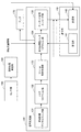
図1は、本開示の実施形態に係る集音システムの概要を説明するための説明図である。図1に示したように、集音システムは、聴診装置1、被検体4に飲み込まれる等して体内に導入されるカプセル型医療装置2(以下、カプセル2とも称す)、および外部装置3を含む。なお、集音システムは、複数のカプセル2(2A、2B、2C)を含んでもよい。また、カプセル2は、通信機能を有し、体外の聴診装置1とデータの送受信を行うことが可能である。そして、聴診装置1も同様に通信機能を有し、外部装置3とデータの送受信を行うことが可能である。
また、図1に示したように、聴診装置1は、本体部11、集音部12、ケーブル13、イヤー部14、および耳管部15を含む。集音部12は、体表面に接触することで、体腔外において体内音を集音する。そして、ケーブル13は、集音部12が集音した体内音を本体部11に伝達する。一方で、カプセル2は、体腔内において体内音を集音する。そして、カプセル2は、体腔内において集音した体内音を、カプセル2との通信機能を有する本体部11に送信する。
As shown in FIG. 1, the
本体部11は、カプセル2が体腔内において集音した体内音と、集音部12が体腔外において集音した体内音とを組み合わせて、観測対象である所定部位(目的部位)の音(目的音)を生成する。耳管部15L、15Rは、本体部11が生成した目的音をイヤー部14L、14Rに伝達する。そして、イヤー部14L、14Rは、耳管部15L、15Rにより伝達された目的音を出力する。
The
なお、本明細書において、体内音とは、体内で発生する音であって、例えば心音、呼吸音、脈拍、および腸音等を示す。また、目的部位とは、例えば心臓、肺、腸管等の内臓を示す。 In the present specification, the internal body sound is a sound generated in the body and indicates, for example, a heart sound, a respiratory sound, a pulse, an intestinal sound, and the like. In addition, the target site indicates internal organs such as the heart, lungs, and intestinal tract.
また、本体部11は、生成した目的音を外部装置3に送信し、外部装置3に目的音を記録させてもよい。また、聴診装置1は、外部装置3に蓄積されている過去の目的音を受信して再生することもできる。
The
以下、このような本開示による集音システムについて複数の実施形態を挙げて詳細に説明する。なお、以下に説明する各実施形態において、本開示による第1の検出部(集音部12)を有する信号処理装置の一例として、電子聴診装置を用いる。また、本開示による第2の検出部の一例としてカプセル型医療装置を用いるが、本開示はかかる例に限定されない。例えば、第2の検出部は、内視鏡型医療装置であってもよい。また、図1に示したように、本開示による外部装置3の一例としてPC(Personal Computer)を示したが、本開示はかかる例に限定されない。例えば、外部装置3は、サーバ、スマートフォン、PDA(Personal Digital Assistants)、ノートPC、携帯電話、携帯用音楽再生装置、携帯用映像処理装置または携帯用ゲーム機器等であってもよい。
Hereinafter, such a sound collection system according to the present disclosure will be described in detail with reference to a plurality of embodiments. In each embodiment described below, an electronic auscultation apparatus is used as an example of a signal processing apparatus having the first detection unit (sound collection unit 12) according to the present disclosure. Moreover, although a capsule medical device is used as an example of the second detection unit according to the present disclosure, the present disclosure is not limited to such an example. For example, the second detection unit may be an endoscope medical device. Further, as illustrated in FIG. 1, a PC (Personal Computer) is illustrated as an example of the
<<2.各実施形態>>
<2−1.第1の実施形態>
本実施形態によれば、カプセル2が体腔内において集音した体内音と、聴診装置1が体腔外において集音した体内音とを組み合わせることで、体腔内の目的部位が発した目的音をより鮮明に生成することが可能である。以下、図2〜5を参照し本実施形態による集音システムに含まれるカプセル2および聴診装置1の構成を順次説明する。
<< 2. Each embodiment >>
<2-1. First Embodiment>
According to the present embodiment, by combining the internal sound collected by the
[2−1−1.カプセル2の構成]
カプセル2は、上述したように、被検体4の体腔内において、体内音を集音し、聴診装置1に送信する。このとき、カプセル2は、集音した体内音に対して所定の信号処理を行った上で送信してもよい。例えば、体内音の観測対象として所定部位や臓器などの目的部位が特定されている場合、他の部位や臓器から発せられる音は不要なノイズとなる。そこで、不要なノイズを低減してS/N比(signal/noise:信号雑音比)を向上させるために、カプセル2は、集音した体内音に対する信号処理として、帯域制限等を行ってもよい。このような帯域制限等の信号処理を行うカプセル2の構成について、図2を参照して説明する。
[2-1-1. Configuration of capsule 2]
As described above, the
図2は、第1の実施形態に係るカプセル2の構成を示した説明図である。図2に示したように、カプセル2は、集音部20、アンプ21、ADC(Analog Digital Converter)22、信号処理部23、および通信部24を有する。
FIG. 2 is an explanatory diagram showing the configuration of the
(集音部)
集音部20は、マイクロフォンとしての機能を有する。集音部20は、体腔内において、体内音を集音(検出)し、オーディオ信号として出力する検出部である。また、集音部20は、指向性を有し、目的部位方向からの音声のみを集音してもよい。なお、以下では、集音部20が検出したオーディオ信号を、体腔内信号と称する。
(Sound collector)
The
(アンプ)
アンプ21は、オーディオ信号を増幅する機能を有する。アンプ21は、集音部20から出力された体腔内信号を増幅して出力する。
(Amplifier)
The
(ADC)
ADC22は、アナログ電気信号をデジタル電気信号に変換する電子回路である。ADC22は、アンプ21から出力された体腔内信号を、アナログ信号からデジタル信号に変換して出力する。
(ADC)
The
(信号処理部)
信号処理部23は、オーディオ信号に対して所定の信号処理を行う機能を有する。信号処理部23は、ADC22から出力された体腔内信号に対して所定の信号処理を行い、出力する。信号処理部23は、例えばDSP(Digital Signal Processor)、またはMPU(Micro−Processing Unit)等の演算装置により実現されてもよい。ここで、図3を参照し、信号処理部23の具体的な構成について詳細に説明する。
(Signal processing part)
The
図3は、第1の実施形態に係る信号処理部23の内部および周辺の構成を示した説明図である。図3に示したように、信号処理部23は、帯域制限デジタルフィルタ部231、ノイズリダクション部232、D−range制御処理部233、およびオーディオ信号エンコーダ部235を含む。また、カプセル2は、さらにセンサ群25および現在位置推定部26を含む。
FIG. 3 is an explanatory diagram showing the internal and peripheral configurations of the
(センサ群)
センサ群25は、例えば圧力センサ、触覚センサ、撮像センサ、加速度センサ、またはpHセンサ等により構成され、カプセル2の周辺の体腔内部の状態を検知する。
(Sensor group)
The
(現在位置推定部)
現在位置推定部26は、センサ群25により検知された各センサ値(pH値等)に基づいて、カプセル2が現在どの部位、どの内臓内にいるのかを推定し、推定結果を現在位置情報として出力する。なお、本明細書において、位置は絶対位置を指すものとして説明するが、被検体4の所定部位または所定の装置等からの相対位置としてもよい。
(Current position estimation unit)
The current
(通信部)
通信部24は、データを無線で送受信する機能を有する。例えば、通信部24は、信号処理部23から出力された体腔内信号、現在位置推定部26から出力された現在位置情報、およびセンサ群25が出力したセンサ値等を無線送信する。また、通信部24は、集音部20から集音され、アンプ21およびADC22を介した体腔内信号、現在位置情報およびセンサ値等を無線送信してもよい。なお、通信部24の通信方式は特に限定せず、例えばWiFi、Bluetooth(登録商標)、ZigBee等であってもよい。
(Communication Department)
The
(帯域制限デジタルフィルタ部)
帯域制限デジタルフィルタ部231(Digital Filter:以下、帯域制限DF部とも称する)は、所定の周波数帯域のオーディオ信号を低減または通過させる機能を有する。帯域制限DF部231は、ADC22から出力された体腔内信号のうち、所定の周波数帯域を通過させることで、S/N比を向上させることができる。また、帯域制限DF部231は、BPF(Band−Pass Filter)、LPF(Low−Pass Filter)、およびHPF(High−Pass Filter)等がデジタル化されたものであって、急峻なフィルタや、直線位相フィルタ等の高精度な制御が可能となる。
(Band-limited digital filter part)
The band limited digital filter unit 231 (Digital Filter: hereinafter also referred to as a band limited DF unit) has a function of reducing or passing an audio signal in a predetermined frequency band. The band limiting
(ノイズリダクション部)
ノイズリダクション部232(Noise Reduction:以下、NR部232とも称す)は、所定のノイズ成分をカットする機能を有する。NR部232は、帯域制限DF部231から出力された体腔内信号から所定のノイズ成分をカットする。本実施形態においては、例えば心音に着目したい観測時において、検出された体腔内信号内に血流音等の連続定常的な音が入っている場合、NR部232は、この血流音をノイズとして扱い、血流音をカットすることが可能である。具体的には、NR部232は、一定期間の集音記録および周波数解析の結果に基づいて、ノイズ(ここでは血流音)を推測し、これを観測期間内のオーディオ信号から周波数軸上で減算するSS(Spectrum Subtraction)等の手法を用いてもよい。
(Noise reduction part)
The noise reduction unit 232 (Noise Reduction: hereinafter also referred to as the NR unit 232) has a function of cutting a predetermined noise component. The
(D−range制御処理部)
D−range制御処理部233は、オーディオ信号の音量の幅を制御する機能を有する。D−range制御処理部233は、NR部232から出力された体腔内信号の音量の幅を制御することで、後述のエンコーダ部235の処理リソースの負担や、通信部24による伝送容量を低減する。その結果、カプセル2の回路規模や消費電力が低減するので、カプセル2はより小型化され、カプセル2を飲み込む被検体4の負担をも低減される。
(D-range control processing unit)
The D-range
(オーディオ信号エンコーダ部)
オーディオ信号エンコーダ部235(以下、エンコーダ部235とも称す)は、オーディオ信号を符号化する機能を有する。エンコーダ部235は、D−range制御処理部233から出力された体腔内信号を符号化して出力する。符号方式は特に限定せず、例えばMP3(MPEG Audio Layer−3)、またはAAC(Advanced Audio Coding)等であってもよい。また、エンコーダ部235の符号方式は、通信部24の通信方式に応じた適切な符号方式であってもよい。
(Audio signal encoder)
The audio signal encoder unit 235 (hereinafter also referred to as an encoder unit 235) has a function of encoding an audio signal. The
なお、カプセル2は、上記説明したように、観測対象とする目的部位を特定する情報、目的部位の位置情報、信号処理部23による信号処理を設定する設定情報等の情報(パラメータ)に基づいて、集音および信号処理を行う。このようなパラメータは、例えば、カプセル2が被検体4の体内に導入される前に設定されていてもよい。他にも、カプセル2が被検体4の体内に導入された後に、外部から無線通信を介してパラメータが設定されてもよい。
Note that, as described above, the
[2−1−2.聴診装置1の構成]
以上、カプセル2の構成について説明した。次に、図4〜5を参照して、聴診装置1の構成について説明する。
[2-1-2. Configuration of auscultation device 1]
The configuration of the
図4は、第1の実施形態に係る聴診装置1の構成を示した説明図である。図4に示したように、聴診装置1の本体部11は、アンプ110、ADC120、信号処理部130、通信部140、およびアンプ170を有する。
FIG. 4 is an explanatory diagram showing the configuration of the
(アンプ、ADC)
アンプ110およびADC120は、アンプ21およびADC22と同様の機能を有し、集音部12から出力されたオーディオ信号(以下、体腔外信号とも称す)の増幅およびデジタル信号への変換を行い、出力する。アンプ170は、アンプ21と同様の機能を有し、後述の信号処理部130から出力される体腔外信号や目的信号を増幅して出力する。
(Amplifier, ADC)
The
(信号処理部)
信号処理部130は、カプセル2が検出した体腔内信号(体腔内において集音した体内音の信号)、および集音部12が検出した体腔外信号(体腔外において集音した体内音の信号)を組み合わせて、目的信号(目的音の信号)を生成する。信号処理部130は、信号処理部23と同様に、例えばDSP(Digital Signal Processor)、またはMPU(Micro−Processing Unit)等の演算装置により実現されてもよい。ここで、図5を参照し、信号処理部130の具体的な構成について詳細に説明する。
(Signal processing part)
The
図5は、第1の実施形態に係る信号処理部130の内部および周辺の構成を示した説明図である。図5に示したように、信号処理部130は、帯域制限デジタルフィルタ部131、ノイズリダクション部132、D−range制御処理部133、双方参照型ノイズリダクション部134、およびエンコーダ部135を含む。また、本体部11は、センサ群150および現在位置推定部160をさらに含む。
FIG. 5 is an explanatory diagram showing the internal and peripheral configurations of the
(センサ群)
センサ群150は、例えば集音部12に設けられる触覚センサ、加速度センサ、ジャイロセンサ等により構成され、集音部12の周辺の状態を検知する。また、センサ群150は、本体部11に設けられるカメラ、赤外線センサ、深度センサ等により構成され、集音部12の周辺の状態を俯瞰的に検知してもよい。
(Sensor group)
The
(現在位置推定部)
現在位置推定部160は、センサ群150により検知された各センサ値(赤外線センサおよび触覚センサによる検知結果等)に基づいて、集音部12が現在体表面のどの位置に接触しているのかを推定し、推定結果を現在位置情報として出力する。
(Current position estimation unit)
The current
(通信部)
通信部140は、通信部24と同様の機能を有する。より詳しくは、通信部140は、データを受信する受信部141としての機能およびデータを送信する送信部142としての機能を有する。
(Communication Department)
The
(受信部)
受信部141は、カプセル2から受信した体腔内信号およびカプセル2の現在位置情報を、双方参照型ノイズリダクション部134に出力する。また、受信部141は、外部装置3から受信した過去の体腔外信号、体腔内信号、および目的信号を、双方参照型NR部134に出力してもよい。なお、本実施形態では、一例として受信部141が送信部142と共に本体部11に配設される例を示したが、本開示はかかる例に限定されない。例えば、受信部141は送信部142と分離した状態で、集音部12に配設されてもよい。この場合、受信部141は、よりカプセル2に近い位置でカプセル2からデータを受信することができる。
(Receiver)
The receiving
(送信部)
送信部142は、後述のエンコーダ部135から出力された目的信号、および現在位置推定部160から出力された集音部12の現在位置情報を外部装置3に無線送信する。また、送信部142は、後述のD−range制御処理部133が出力した体腔外信号と、受信部141から出力された体腔内信号およびカプセル2の現在位置情報とを、外部装置3に無線送信してもよい。また、送信部142は、集音部12から集音され、アンプ110およびADC120を介した体腔外信号および集音部12の現在位置情報を外部装置3に送信してもよい。さらに、送信部142は、上述のカプセル2における集音および信号処理に用いるパラメータを、カプセル2に送信してもよい。なお、本実施形態では、通信部140が外部装置3と無線通信する例を説明するが、有線通信であってもよい。
(Transmitter)
The
(帯域制限デジタルフィルタ部)
帯域制限デジタルフィルタ部131(以下、帯域制限DF部131とも称す)は、帯域制限DF部231と同様の機能を有する。ノイズリダクション部132(以下、NR部132とも称す)は、NR部232と同様の機能を有する。D−range制御処理部133は、D−range制御処理部233と同様の機能を有する。そして、帯域制限DF部131、NR部132およびD−range制御処理部133は、集音部12が出力した体腔外信号に対して、帯域制限DF部231、NR部232およびD−range制御処理部233と同様の信号処理を行う。
(Band-limited digital filter part)
The band-limited digital filter unit 131 (hereinafter also referred to as a band-limited DF unit 131) has the same function as the band-limited
(双方参照型ノイズリダクション部)
双方参照型ノイズリダクション部134(以下、双方参照型NR部134とも称す)は、複数のオーディオ信号を用いて所定の音源からのオーディオ信号のS/N比を向上させて抽出する機能を有する。本実施形態においては、双方参照型NR部134は、受信部141により受信した体腔内信号と、帯域制限DF部131から出力された体腔外信号とを組み合わせて、目的信号を生成して出力する。なお、双方参照型NR部134は、体腔内信号と体腔外信号とを組み合わせる際に、現在位置推定部160から出力された集音部12の現在位置情報および受信部141から出力されたカプセル2の現在位置情報を用いる。
(Both reference type noise reduction part)
The bi-reference noise reduction unit 134 (hereinafter also referred to as bi-reference type NR unit 134) has a function of improving and extracting the S / N ratio of an audio signal from a predetermined sound source using a plurality of audio signals. In the present embodiment, the
(オーディオ信号エンコーダ部)
オーディオ信号エンコーダ部135(以下、エンコーダ部135とも称す)は、エンコーダ部235と同様の機能を有し、双方参照型NR部134から出力されたオーディオ信号を符号化して出力する。
(Audio signal encoder)
The audio signal encoder unit 135 (hereinafter also referred to as the encoder unit 135) has the same function as the
以上、聴診装置1の本体部11の各構成について詳細に説明した。なお、本体部11は、上記説明した以外に、体腔外信号、体腔内信号、または目的信号の少なくともいずれかを記憶する記憶部、各種設定を行う操作入力部、および聴診装置1の動作電力を蓄電するバッテリー等を含んでもよい。
In the above, each structure of the main-
また、聴診装置1は、カプセル2と同様に、観測対象とする目的部位を特定する情報、目的部位の位置情報等の情報(パラメータ)に基づいて、集音および信号処理を行う。このような聴診装置1およびカプセル2で用いるパラメータは、操作入力部により設定されてもよい。他にも、目的部位は、集音部12の位置に最も距離が近い、又は正面に位置する内臓であるして、集音部12の位置に応じて自動的に聴診装置1が設定してもよい。
Similarly to the
また、聴診装置1は、体腔外信号、体腔内信号または目的信号を取得した際に記憶部に記憶させて、後の任意のタイミングでこれらの信号を外部装置3に送信してもよい。
The
また、記憶部は、例えば半導体メモリ、磁気ディスク、または光ディスクなどによって構成され、聴診装置1が機能するために必要な各種のデータを格納してもよい。そして、聴診装置1は、記憶部に格納されたプログラムを読み出して実行することによって動作してもよい。
Further, the storage unit is configured by, for example, a semiconductor memory, a magnetic disk, or an optical disk, and may store various data necessary for the
[2−1−3.動作]
以上、本実施形態に係る集音システムの構成を説明した。続いて、図6〜9を参照し、本実施形態に係る集音システムの動作を説明する。
[2-1-3. Operation]
The configuration of the sound collection system according to this embodiment has been described above. Subsequently, the operation of the sound collection system according to the present embodiment will be described with reference to FIGS.
図6は、第1の実施形態に係る集音システムの動作処理を示すシーケンス図である。図6に示したように、聴診装置1は、ひとつ以上のカプセル2が集音した体内音を用いて、目的音を再生し得る。
FIG. 6 is a sequence diagram showing an operation process of the sound collection system according to the first embodiment. As shown in FIG. 6, the
まず、ステップS104で、送信部142は、体腔内に導入されたカプセル2に対してオーディオ信号の送信指示およびパラメータを送信し、通信部24により受信される。ここでのパラメータとは、上述のカプセル2における集音および信号処理に用いるパラメータである。
First, in step S <b> 104, the
なお、送信部142は、体腔内に導入されたひとつ以上のカプセル2のうち、体外に位置する集音部12に最も近い位置に存在するカプセル2に、送信指示を送信してもよい。他にも、送信部142は、集音部12の位置から所定距離の範囲に存在するカプセル2に、送信指示を送信してもよい。以下では、送信部142が、カプセル2Aおよび2Bに送信指示を送信した例を説明する。
Note that the
続いて、ステップS108で、集音部12は、体腔外から体内音を集音する。そして、ステップS112で、信号処理部130は、集音部12が集音した体内音に対して信号処理を行う。具体的には、信号処理部130は、集音部12が出力した体腔外信号に対して、帯域制限DF部131による帯域制限、NR部132によるノイズ成分のカット、D−range制御処理部133による音量の幅の制御を行う。
Subsequently, in step S108, the
そして、聴診装置1から送信指示を受信したカプセル2Aは、送信指示に付加されているパラメータが示す目的部位を対象として、体内音の集音および信号処理を行う。より詳しくは、ステップS108Aで、集音部20は、体腔内において体内音を集音する。そして、ステップS112Aで、信号処理部23は、集音部20が集音した体内音に対して信号処理を行う。具体的には、信号処理部23は、集音部20が出力した体腔内信号に対して、帯域制限DF部231による帯域制限、NR部232によるノイズ成分のカット、D−range制御処理部233による音量の幅の制御を行う。
Then, the
カプセル2BによるステップS108BおよびS112Bにおける動作は、カプセル2Aについて上記説明したステップS108AおよびS112Aと同様であるので、ここでの説明は省略する。
Since the operation in steps S108B and S112B by the
その後、ステップS116で、カプセル2Aおよび2Bは、聴診装置1に対して体腔内信号およびパラメータを送信し、受信部141により受信される。ここでのパラメータとは、カプセル2の現在位置情報、カプセル2の周辺の状態を示すセンサ値、集音部20が集音した時刻である。
Thereafter, in step S116, the
続いて、ステップS120で、聴診装置1は、S112でD−range制御処理部133が出力した体腔外信号と、ステップS116で受信部141が受信した体腔内信号およびパラメータとを、外部装置3に対して送信する。ここでのパラメータとは、集音部12およびカプセル2の現在位置情報、ならびに集音部12および集音部20が集音した時刻である。
Subsequently, in step S120, the
そして、ステップS124で、聴診装置1は、信号生成処理を行う。詳しくは、双方参照型NR部134が、時間差補正処理と目的音生成処理とを行う。時間差補正処理とは、双方参照型NR部134は、S112でD−range制御処理部133が出力した体腔外信号と、ステップS116で受信部141が受信した体腔内信号との時間差を補正して同期させる処理である。また、目的音生成処理とは、時間差補正処理により同期した体腔外信号と体腔内信号から、目的信号を分離する処理である。なお、時間差補正処理および目的音生成処理については、後に詳細に説明する。
In step S124, the
その後、ステップS128で、聴診装置1は、双方参照型NR部134が生成した目的信号に基づいて目的音を再生する。より詳しくは、アンプ170が双方参照型NR部134から出力された目的信号を増幅し、イヤー部14Rおよび14Lがアンプ170により増幅された目的信号を目的音として再生する。
Thereafter, in step S128, the
次に、ステップS132で、聴診装置1は、外部装置3に対して目的信号およびパラメータを送信する。より詳しくは、エンコーダ部135が双方参照型NR部134から出力された目的信号を符号化し、送信部142がエンコーダ部135により符号化された目的信号を外部装置3に対して送信する。ここでのパラメータとは、集音部12およびカプセル2の現在位置情報、ならびに集音部12および集音部20が集音した時刻である。なお、ステップS132は、ステップS128より前に実行されてもよい。
Next, in step S <b> 132, the
最後に、ステップS136で、外部装置3は、ステップS120およびS132において聴診装置1より受信した目的信号およびパラメータを記憶する。
Finally, in step S136, the
(時間差補正処理)
以下では、ステップS124における双方参照型NR部134による時間差補正処理について、詳細に説明する。まず、図7を参照して、集音部12が集音した体内音とカプセル2が集音した体内音との間に時間差が生じる要因について説明する。
(Time difference correction processing)
Hereinafter, the time difference correction process by the
図7は、第1の実施形態に係るカプセル2、集音部12、および目的部位の位置関係を説明するための説明図である。図7に示したように、集音部12、カプセル2Aおよび2Bは、目的部位40までの距離がそれぞれ異なり得る。また、目的部位40と聴診装置1、カプセル2Aおよび2Bとの間には、筋肉、体液、内臓、骨、皮膚等が異なった構成で存在し得る。
FIG. 7 is an explanatory diagram for explaining the positional relationship among the
一般的に、音声は、音源まで距離や音源との間に存在する物質の材質等に応じて伝導性が変化する。従って、集音部12が集音した体内音と、カプセル2Aが集音した体内音、カプセル2Bが集音した体内音には、目的部位40までの距離や材質等に応じた時間差が発生する。そこで、双方参照型NR部134は、目的部位40までの距離や材質等に応じて音声の時間差を補正して同期させる。ここで、双方参照型NR部134は、目的部位(40)までの距離を絶対位置情報によって、材質をカプセル2の周辺の状態を示すセンサ値によって推定する。
Generally, the conductivity of sound changes depending on the distance to the sound source and the material of the substance existing between the sound source and the like. Therefore, a time difference corresponding to the distance to the
このような時間差補正処理の具体例について、以下図8を参照して説明する。 A specific example of such time difference correction processing will be described below with reference to FIG.
図8は、第1の実施形態に係る双方参照型NR部134による時間差補正処理の一例を説明するための説明図である。図8に示したように、双方参照型NR部134は、時間差算出部136としての機能と、時間差補正部137としての機能と、目的音抽出部138としての機能を有する。
FIG. 8 is an explanatory diagram for explaining an example of a time difference correction process by the
時間差算出部136は、現在位置推定部160が出力した集音部12の現在位置情報と、カプセル2Aおよび2Bから受信したカプセル2Aおよび2B現在位置情報と、目的部位の位置情報とに基づいて、各オーディオストリーム間の時間差を算出する。時間差補正部137は、まず、集音部12、カプセル2Aおよび2Bが集音した体内音のオーディオストリームをバッファリングする。そして、時間差補正部137は、時間差算出部136が算出した時間差に応じたストリーム位置から各オーディオストリームを読み出し目的音抽出部138に出力する。
The time
なお、上記では、時間差算出部136は、オーディオストリームをバッファリングした後に、時間差に応じたストリーム位置から各オーディオストリームを読み出すとしたが、本開示はかかる例に限定されない。例えば、時間差算出部136は、バッファリングの際に、時間差に応じたストリーム位置に各オーディオストリームを書き込んでもよい。
In the above description, the time
このようにして、時間差算出部136および時間差補正部137は、体腔外信号と体腔内信号との時間差を補正して同期させる。続いて、目的音抽出部138が目的音を抽出および生成する。
In this way, the time
(目的音生成処理)
以下では、ステップS124における双方参照型NR部134による目的音生成処理について、具体例を用いて詳細に説明する。
(Target sound generation processing)
Hereinafter, the target sound generation processing by the
例えば、聴診装置1による体腔外信号T、カプセル2Aによる体腔内信号C1およびカプセル2Bによる体腔内信号C2を、心音X、呼吸音Yおよびどちらにも分類できないノイズNが混在する信号として、以下のように表す。
For example, the body cavity outside the signal T by
聴診装置1による体腔外信号 T = A0・X+B0・Y+N0 …(数式1)
カプセル2Aによる体腔内信号 C1 = A1・X+B1・Y+N1 …(数式2)
カプセル2Bによる体腔内信号 C2 = A2・X+B2・Y+N2 …(数式3)
Extracorporeal signal by auscultation device 1 T = A 0 · X + B 0 · Y + N 0 (Formula 1)
Signal in body cavity by
Signal in body cavity by
ここで、A(A0、A1、A2)およびB(B0、B1、B2)を係数とする。 Here, A (A 0 , A 1 , A 2 ) and B (B 0 , B 1 , B 2 ) are used as coefficients.
なお、係数AおよびBは、音源から各集音部への伝達関数として捉えてもよい。係数Aについてより詳しく説明すると、係数A0、A1、A2を、心臓位置から、それぞれ集音部12、カプセル2Aおよび2B、の位置へ向けた伝達関数として捉えてもよい。係数A0、A1 、A2は心臓位置から各集音部の位置までの音の伝導性を周波数特性で示すものであり、各集音部の位置および伝達経路の材質によって定まるものである。
The coefficients A and B may be taken as transfer functions from the sound source to each sound collection unit. The coefficient A will be described in more detail. The coefficients A 0 , A 1 , and A 2 may be regarded as transfer functions from the heart position to the positions of the
具体的に、係数A0、A1、A2は、経験則、またはシミュレーションによって、心臓から各位置への音の伝導特性を推定される。他にも、センサ群25により検知されたセンサ値によって推定されてもよい。また、被検体4が手術のために開腹した場合に、心臓や肺などの目的部位となりえる部位と、胃管や腸管などのカプセル2が通過し得る部位との間の伝達関数を測定し、後に係数Aとして用いてもよい。
Specifically, the coefficients A 0 , A 1 , and A 2 are estimated from sound conduction characteristics from the heart to each position by an empirical rule or simulation. In addition, it may be estimated by a sensor value detected by the
また、より簡易には、係数A0、A1 、A2は、伝達経路の音の伝導性が未知であっても、心臓位置から各集音部の位置までの距離、音の減衰度合および距離による時間遅延により定まる。 More simply, the coefficients A 0 , A 1 , A 2 are the distance from the heart position to the position of each sound collection unit, the sound attenuation level, and the sound conductivity even if the sound conductivity of the transmission path is unknown. Determined by time delay due to distance.
係数Bは、係数Aについて説明した上記と同様であるので、ここでの説明は省略する。 The coefficient B is the same as that described above for the coefficient A, and thus description thereof is omitted here.
また、N0、N1、N2は、例えばノイズ発生源となる部位を特定した上で、過去にカプセル2がノイズ発生源付近を通過した時に集音した体内音をとしてもよい。
N 0 , N 1 , and N 2 may be body sounds collected when the
上述のように、A、BおよびNが既知である、または別手段により算出することができる場合は、目的音抽出部138は、上記数式1−3の逆行列を求める、または連立方程式を解く等により、XおよびYを算出することができる。 As described above, when A, B, and N are known or can be calculated by another means, the target sound extraction unit 138 obtains an inverse matrix of the above Equation 1-3 or solves simultaneous equations. Thus, X and Y can be calculated.
一方で、双方参照型NR部134は、A、BおよびNを未知としたままで、ブラインド音源分離、ブラインド信号源分離、主成分分析、独立成分分析等の多様な音源分離の手法、またはこれらの組み合わせによって、XおよびYを算出することもできる。
On the other hand, the bi-reference
(より簡易な目的音生成処理)
また、目的音抽出部138は、上述の目的音生成処理と比較して、より簡易に目的音を抽出できる場合がある。まず、説明の簡略化のため、聴診装置1による体腔外信号T、カプセル2による体腔内信号C1を、心音XおよびノイズNが混在する信号として、以下のように表す。
(Simpler target sound generation process)
In addition, the target sound extraction unit 138 may be able to extract the target sound more easily than the above-described target sound generation process. First, for simplicity of explanation, the body cavity outside the signal T by
聴診装置1による体腔外信号 T = A0・X+N0 …(数式4)
カプセル2Aによる体腔内信号 C1 = A1・X+N1 …(数式5)
Extracorporeal signal by auscultation device 1 T = A 0 · X + N 0 (Formula 4)
Body cavity signal from
このとき、ノイズNの周波数分布特性が心音Xと明らかに異なる場合には、目的音抽出部138は、(T−αC1)としたときに、体腔外信号TからノイズNの周波数分布特性が相殺されるようなαを求めることで、S/N比よく心音Xを抽出することができる。このようなαは、{(A0−αA1)X+(N0−αN1)}について、(N0−αN1)を最小化し得る。 At this time, if the frequency distribution characteristic of the noise N is clearly different from the heart sound X, the target sound extraction unit 138 determines that the frequency distribution characteristic of the noise N from the extracorporeal signal T is (T−αC 1 ). The heart sound X can be extracted with a high S / N ratio by obtaining α that is canceled out. Such α can minimize (N 0 −αN 1 ) for {(A 0 −αA 1 ) X + (N 0 −αN 1 )}.
なお、心音Xが低域のみである場合には、伝達関数における時間遅延要素は無視できるため、A0、A1をそれぞれの音量を示すゲイン値として、(A0−αA1)をスカラー値として捉えることができる。ここで、診断に用いる体内音としては、波形形状および時間推移等が重視されるため、目的音抽出部138は(A0−αA1)を算出しなくてもよい。 When the heart sound X is only in the low frequency range, the time delay element in the transfer function can be ignored. Therefore, A 0 and A 1 are gain values indicating the respective volumes, and (A 0 −αA 1 ) is a scalar value. Can be understood as Here, as the body sound used for diagnosis, since the waveform shape, time transition, and the like are emphasized, the target sound extraction unit 138 does not have to calculate (A 0 −αA 1 ).
このようなαを求める具体例について、以下図9を参照して説明する。 A specific example of obtaining such α will be described below with reference to FIG.
図9は、第1の実施形態に係る目的音抽出部138による目的音生成処理の一例を説明するための説明図である。図9に示したように、まず、所定のαを用いて(T−αC1)を算出する。そして、αを逐次変更させながら、S/N比よく心音Xを抽出することができる最適なαを探索する。 FIG. 9 is an explanatory diagram for explaining an example of target sound generation processing by the target sound extraction unit 138 according to the first embodiment. As shown in FIG. 9, first, (T−αC 1 ) is calculated using a predetermined α. Then, an optimum α that can extract the heart sound X with a high S / N ratio is searched while sequentially changing α.
目的音抽出部138は、心音Xの周波数分布特性が既知である場合、心音Xの中心となる帯域を通過するようなBPF(Band−Pass Filter)によって目的音期待成分を算出する。一方で、目的音抽出部138は、心音Xの中心となる帯域を遮断するBEF(Band Elimination Filter)によって、ノイズ音期待成分を算出する。 When the frequency distribution characteristic of the heart sound X is known, the target sound extraction unit 138 calculates the target sound expectation component by a BPF (Band-Pass Filter) that passes through the band that is the center of the heart sound X. On the other hand, the target sound extraction unit 138 calculates an expected noise sound component by BEF (Band Elimination Filter) that cuts off the center band of the heart sound X.
そして、目的音抽出部138は、BPFおよびBEFからの出力信号を、それぞれ平均化して信号QおよびRを算出する。その後、目的音抽出部138は、信号QおよびRを評価して最適なαを探索する。具体的には、目的音抽出部138は、αを逐次変更させるシーケンス制御を行いながら、信号Qを最大化し信号Rを最小化するような最適なαを算出する。 Then, the target sound extraction unit 138 calculates the signals Q and R by averaging the output signals from the BPF and BEF, respectively. Thereafter, the target sound extraction unit 138 evaluates the signals Q and R and searches for the optimum α. Specifically, the target sound extraction unit 138 calculates an optimal α that maximizes the signal Q and minimizes the signal R while performing sequence control that sequentially changes α.
なお、信号Qを最大化するαと信号Rを最小化するαとが一致しない場合がある。この場合は、例えば、双方に重み付けを行い最適なαを算出する。また、最適なαは時間経過によって変化する可能性があるため、目的音抽出部138は、最適なαを算出後所定の時間経過後に、再度最適なαを算出してもよい。 Note that α that maximizes the signal Q may not match α that minimizes the signal R. In this case, for example, the optimum α is calculated by weighting both. In addition, since the optimal α may change with time, the target sound extraction unit 138 may calculate the optimal α again after a predetermined time has elapsed after calculating the optimal α.
また、以上説明した例では、聴診装置1による体腔外信号およびカプセル2Aによる体腔内信号の引き算を時間軸上で行うとしたが、本開示はかかる例に限定されない。例えば、当該引き算を、周波数軸上でSS(Spectrum Subtraction)として実行してもよい。具体的には、目的音抽出部138は、心音Xが支配的な信号(体腔内信号または体腔外信号)とノイズNが支配的な信号との周波数軸上の差分により、心音Xを抽出してもよい。
Moreover, in the example demonstrated above, although the subtraction of the extracorporeal signal by the
(補足)
なお、上記説明した例では、双方参照型NR部134は、カプセル2において信号処理が行われた体腔内信号を、同様に信号処理を行った体腔外信号に組み合わせるとしたが、本開示はかかる例に限定されない。例えば、カプセル2は、信号処理を行っていない、または帯域制限等の最小限の信号処理のみを行った体腔内信号を聴診装置1に送信してもよい。そして、聴診装置1は、カプセル2から受信した体腔内信号に対して、NR部132およびD−range制御処理部133等を介して信号処理を行った上で、双方参照型NR部134により体腔外信号と組み合わせてもよい。
(Supplement)
In the example described above, the bi-reference
[2−1−4.効果]
以上説明したように、本実施形態に係る集音システムは、体腔内において集音した体内音と、体腔外から集音した体内音とを組み合わせることで、体腔内の目的部位が発した目的音をより鮮明に取得することが可能である。また、体腔外における集音部12と体腔内における集音部20とは、目的部位までの距離、周辺の状態、集音方向等が異なるため、双方参照型NR部134は、独立性の高い音声の組み合わせによって、目的音をS/N比よく抽出することができる。
[2-1-4. effect]
As described above, the sound collection system according to the present embodiment combines the body sound collected in the body cavity with the body sound collected from outside the body cavity, so that the target sound emitted from the target site in the body cavity is obtained. Can be obtained more clearly. In addition, since the
また、カプセル2は、体腔内において体内音を集音するので、体表面に集音部をあてて体腔外から体内音を集音する一般的な聴診器よりも、より鮮明に体内音を取得することができる。従って、本実施形態に係る集音システムは、体腔外から集音した複数の体内音を組み合わせて目的音を抽出する比較例と比較して、より鮮明に目的音を抽出することができる。
このように、本実施形態によれば、不整脈、心雑音、喘鳴、腸雑音等の異常音等の、診断に用いられる体内音をより鮮明に取得することで、心臓、肺、腸管の異常部位の早期発見等が可能となり、医療技術が革新的に進歩する。 Thus, according to the present embodiment, abnormal parts of the heart, lungs, and intestinal tract can be obtained more clearly by acquiring body sounds used for diagnosis, such as abnormal sounds such as arrhythmia, heart noise, wheezing, and intestinal noise. The medical technology will be innovatively advanced.
また、聴診装置1は、体内音の観測者(医者)が従来使い慣れた一般的な聴診器と同様の形状である。従って、観測者は、直観的に聴診装置1を使用することが可能である。
Further, the
<2−2.第2の実施形態>
本実施形態によれば、外部装置3が過去に記録した音声を、聴診装置1が再生することが可能である。本実施形態の構成は、[2−1−1.カプセル2の構成][2−1−2.聴診装置1の構成]において説明した通りであるので、ここでの説明は省略する。以下では、図10を参照し、本実施形態の動作を説明する。
<2-2. Second Embodiment>
According to the present embodiment, the
[2−2−1.動作]
図10は、第2の実施形態に係る集音システムの動作処理を示すシーケンス図である。
[2-2-1. Operation]
FIG. 10 is a sequence diagram illustrating an operation process of the sound collection system according to the second embodiment.
まず、ステップS204で、送信部142は、外部装置3に対してオーディオ信号の送信指示およびパラメータを送信する。ここでのパラメータとは、目的部位を特定する情報、目的部位の位置情報、再生対象となる過去の時刻等の情報である。
First, in step S <b> 204, the
続いて、ステップS208で、外部装置3は、聴診装置1に対してオーディオ信号およびパラメータを送信する。ここでのオーディオ信号とは、過去に聴診装置1より受信した目的信号、体腔外信号または体腔内信号またはこれらの組み合わせである。また、パラメータとは過去に聴診装置1が当該オーディオ信号を送信した時点における、聴診装置1およびカプセル2の位置、時刻等の情報である。
Subsequently, in step S208, the
最後に、ステップS212で、聴診装置1は、外部装置3より受信したオーディオ信号を再生する。このとき、受信したオーディオ信号に何ら信号処理を行わずに再生してもよい。他にも、聴診装置1は、双方参照型NR部134により、受信したパラメータに基づいて、受信した体腔外信号および体腔内信号に対して上述の信号処理を行った上で、目的音として再生してもよい。
Finally, in step S212, the
[2−2−2.効果]
上記説明したように、本実施形態によれば、聴診装置1は外部装置3が過去に記録した音声を再生することができる。このため、観測者は、体内音を繰り返し聴いて、より良好な診断を行うことができる。また、体内音の観測者は、過去の体内音と現在の体内音とを比較して診断を行うことができる。
[2-2-2. effect]
As described above, according to the present embodiment, the
また、聴診装置1は、目的信号だけでなく、双方参照型NR部134による信号処理が行われていない体腔内信号および体腔内信号を、受信して再生することができる。従って、信号処理が行われていない体内音が、後から病理の原因究明に必要になった場合であっても、聴診装置1およびカプセル2は再度の集音を行う必要が無い。
In addition, the
<<3.まとめ>>
以上、添付図面を参照しながら本開示の好適な実施形態について詳細に説明したが、本開示の技術的範囲はかかる例に限定されない。本開示の技術分野における通常の知識を有する者であれば、特許請求の範囲に記載された技術的思想の範疇内において、各種の変更例または修正例に想到し得ることは明らかであり、これらについても、当然に本開示の技術的範囲に属するものと了解される。
<< 3. Summary >>
The preferred embodiments of the present disclosure have been described in detail above with reference to the accompanying drawings, but the technical scope of the present disclosure is not limited to such examples. It is obvious that a person having ordinary knowledge in the technical field of the present disclosure can come up with various changes or modifications within the scope of the technical idea described in the claims. Of course, it is understood that it belongs to the technical scope of the present disclosure.
例えば、上記実施形態では、心臓、肺、腸管等の内臓を目的部位とし、血流音をノイズとしたが、本技術はかかる例に限定されない。例えば、聴診装置1およびカプセル2は、血管を目的部位とし、心臓、肺、腸管等の内臓が発する音をノイズとして、血流音を抽出および生成してもよい。
For example, in the above-described embodiment, the internal organs such as the heart, the lungs, and the intestinal tract are used as the target site, and the blood flow sound is used as noise. However, the present technology is not limited to such an example. For example, the
なお、以下のような構成も本開示の技術的範囲に属する。
(1)
体腔外において、体腔内の所定部位の第1のオーディオ信号を検出する第1の検出部と、
体腔内において、当該体腔内の所定部位の第2のオーディオ信号を検出する第2の検出部と、
前記第1のオーディオ信号および前記第2のオーディオ信号に基づいて、第3のオーディオ信号を生成する生成部と、
を備える、信号処理システム。
(2)
前記第2の検出部は、体腔内に導入されるカプセル型医療装置である、前記(1)に記載の信号処理システム。
(3)
前記第2の検出部は、体腔内に導入される内視鏡型医療装置である、前記(1)に記載の信号処理システム。
(4)
前記信号処理システムは、
複数の前記第2の検出部を備える、前記(1)〜(3)のいずれか一項に記載の信号処理システム。
(5)
前記生成部は、前記第1の検出部と前記所定部位との間の距離と、前記第2の検出部と前記所定部位との間の距離とに基づいて、前記第1のオーディオ信号と前記第2のオーディオ信号との時間差を補正した上で、前記第3のオーディオ信号を生成する、前記(1)〜(4)のいずれか一項に記載の信号処理システム。
(6)
前記生成部は、時間差を補正した前記第1のオーディオ信号および前記第2のオーディオ信号から、前記所定部位が発するオーディオ信号を分離することで、前記第3のオーディオ信号を生成する、前記(5)に記載の信号処理システム。
(7)
前記信号処理システムは、
前記第3のオーディオ信号を符号化する符号化部と、
前記符号化部により符号化された第3のオーディオ信号を外部装置に送信する送信部と、
をさらに備える、前記(1)〜(6)のいずれか一項に記載の信号処理システム。
(8)
前記信号処理システムは、前記第1の検出部の位置に応じて、過去に前記外部装置が受信し蓄積した第3のオーディオ信号を前記外部装置から受信する受信部をさらに備える、前記(7)に記載の信号処理システム。
(9)
前記信号処理システムは、前記生成部により生成した第3のオーディオ信号または前記受信部により受信した第3のオーディオ信号を再生する再生部をさらに備える、前記(8)に記載の信号処理システム。
(10)
体腔外において、体腔内の所定部位の第1のオーディオ信号を検出する第1の検出部と、
前記第1のオーディオ信号と、体腔内において、当該体腔内の所定部位の第2のオーディオ信号を検出する第2の検出部により検出された第2のオーディオ信号とに基づいて、第3のオーディオ信号を生成する生成部と、
を備える、信号処理装置。
(11)
前記信号処理装置は、電子聴診装置であって、
前記第2の検出部は、体腔内に導入されるカプセル型医療装置である、前記(10)に記載の信号処理装置。
(12)
前記信号処理装置は、電子聴診装置であって、
前記第2の検出部は、体腔内に導入される内視鏡型医療装置である、前記(10)に記載の信号処理装置。
(13)
前記生成部は、前記第1のオーディオ信号と、複数の前記第2の検出部により検出された複数の前記第2のオーディオ信号とに基づいて、前記第3のオーディオ信号を生成する、前記(10)〜(12)のいずれか一項に記載の信号処理装置。
(14)
前記生成部は、前記第1の検出部と前記所定部位との間の距離と、前記第2の検出部と前記所定部位との間の距離とに基づいて、前記第1のオーディオ信号と前記第2のオーディオ信号との時間差を補正した上で、前記第3のオーディオ信号を生成する、前記(10)〜(13)のいずれか一項に記載の信号処理装置。
(15)
コンピュータに、
体腔外において、当該体腔内の所定部位の第1のオーディオ信号を検出するステップと、
体腔内において、当該体腔内の所定部位の第2のオーディオ信号を検出するステップと、
前記第1のオーディオ信号および前記第2のオーディオ信号より、第3のオーディオ信号を生成するステップと、
を実行させるためのプログラム。
(16)
コンピュータに、
体腔外において、当該体腔内の所定部位の第1のオーディオ信号を検出するステップと、
前記第1のオーディオ信号と、体腔内において検出された、当該体腔内の所定部位の第2のオーディオ信号とにより、第3のオーディオ信号を生成するステップと、
を実行させるためのプログラム。
The following configurations also belong to the technical scope of the present disclosure.
(1)
A first detection unit for detecting a first audio signal of a predetermined part in the body cavity outside the body cavity;
A second detection unit for detecting a second audio signal of a predetermined part in the body cavity in the body cavity;
A generating unit that generates a third audio signal based on the first audio signal and the second audio signal;
A signal processing system comprising:
(2)
The signal processing system according to (1), wherein the second detection unit is a capsule medical device introduced into a body cavity.
(3)
The signal processing system according to (1), wherein the second detection unit is an endoscope medical device introduced into a body cavity.
(4)
The signal processing system includes:
The signal processing system according to any one of (1) to (3), including a plurality of the second detection units.
(5)
The generator generates the first audio signal and the first audio signal based on a distance between the first detector and the predetermined portion and a distance between the second detector and the predetermined portion. The signal processing system according to any one of (1) to (4), wherein the third audio signal is generated after correcting a time difference with the second audio signal.
(6)
The generation unit generates the third audio signal by separating an audio signal emitted from the predetermined portion from the first audio signal and the second audio signal with the time difference corrected, (5 ) Signal processing system.
(7)
The signal processing system includes:
An encoding unit for encoding the third audio signal;
A transmission unit that transmits the third audio signal encoded by the encoding unit to an external device;
The signal processing system according to any one of (1) to (6), further including:
(8)
The signal processing system further includes a receiving unit that receives, from the external device, a third audio signal that has been received and accumulated in the past by the external device according to the position of the first detection unit. The signal processing system described in 1.
(9)
The signal processing system according to (8), further including a reproducing unit that reproduces the third audio signal generated by the generating unit or the third audio signal received by the receiving unit.
(10)
A first detection unit for detecting a first audio signal of a predetermined part in the body cavity outside the body cavity;
Based on the first audio signal and the second audio signal detected by the second detection unit that detects the second audio signal of the predetermined part in the body cavity in the body cavity, the third audio A generator for generating a signal;
A signal processing apparatus comprising:
(11)
The signal processing device is an electronic auscultation device,
The signal processing device according to (10), wherein the second detection unit is a capsule medical device introduced into a body cavity.
(12)
The signal processing device is an electronic auscultation device,
The signal processing device according to (10), wherein the second detection unit is an endoscope medical device introduced into a body cavity.
(13)
The generation unit generates the third audio signal based on the first audio signal and the plurality of second audio signals detected by the plurality of second detection units. The signal processing device according to any one of 10) to (12).
(14)
The generator generates the first audio signal and the first audio signal based on a distance between the first detector and the predetermined portion and a distance between the second detector and the predetermined portion. The signal processing device according to any one of (10) to (13), wherein the third audio signal is generated after correcting a time difference with the second audio signal.
(15)
On the computer,
Detecting a first audio signal of a predetermined site in the body cavity outside the body cavity;
Detecting a second audio signal of a predetermined part in the body cavity in the body cavity;
Generating a third audio signal from the first audio signal and the second audio signal;
A program for running
(16)
On the computer,
Detecting a first audio signal of a predetermined site in the body cavity outside the body cavity;
Generating a third audio signal from the first audio signal and the second audio signal at a predetermined site in the body cavity detected in the body cavity;
A program for running
1 聴診装置
11 本体部
12 集音部
13 ケーブル
14 イヤー部
15 耳管部
110 アンプ
130 信号処理部
131 帯域制限デジタルフィルタ部(帯域制限DF部)
132 ノイズリダクション部(NR部)
133 D−range制御処理部
134 双方参照型ノイズリダクション部(双方参照型NR部)
135 オーディオ信号エンコーダ部(エンコーダ部)
136 時間差算出部
137 時間差補正部
138 目的音抽出部
140 通信部
141 受信部
142 送信部
150 センサ群
160 現在位置推定部
170 アンプ
2 カプセル(カプセル型医療装置)
20 集音部
21 アンプ
22 ADC
23 信号処理部
24 通信部
25 センサ群
26 現在位置推定部
231 帯域制限デジタルフィルタ部(帯域制限DF部)
232 ノイズリダクション部(NR部)
233 D−range制御処理部
235 オーディオ信号エンコーダ部(エンコーダ部)
3 外部装置
4 被検体
40 目的部位
DESCRIPTION OF
132 Noise reduction part (NR part)
133 D-range
135 Audio signal encoder section (encoder section)
136 Time
20
23
232 Noise reduction part (NR part)
233 D-range
3
Claims (16)
体腔内において、当該体腔内の所定部位の第2のオーディオ信号を検出する第2の検出部と、
前記第1のオーディオ信号および前記第2のオーディオ信号に基づいて、第3のオーディオ信号を生成する生成部と、
を備える、信号処理システム。 A first detection unit for detecting a first audio signal of a predetermined part in the body cavity outside the body cavity;
A second detection unit for detecting a second audio signal of a predetermined part in the body cavity in the body cavity;
A generating unit that generates a third audio signal based on the first audio signal and the second audio signal;
A signal processing system comprising:
複数の前記第2の検出部を備える、請求項1に記載の信号処理システム。 The signal processing system includes:
The signal processing system according to claim 1, comprising a plurality of the second detection units.
前記第3のオーディオ信号を符号化する符号化部と、
前記符号化部により符号化された第3のオーディオ信号を外部装置に送信する送信部と、
をさらに備える、請求項1に記載の信号処理システム。 The signal processing system includes:
An encoding unit for encoding the third audio signal;
A transmission unit that transmits the third audio signal encoded by the encoding unit to an external device;
The signal processing system according to claim 1, further comprising:
前記第1のオーディオ信号と、体腔内において、当該体腔内の所定部位の第2のオーディオ信号を検出する第2の検出部により検出された第2のオーディオ信号とに基づいて、第3のオーディオ信号を生成する生成部と、
を備える、信号処理装置。 A first detection unit for detecting a first audio signal of a predetermined part in the body cavity outside the body cavity;
Based on the first audio signal and the second audio signal detected by the second detection unit that detects the second audio signal of the predetermined part in the body cavity in the body cavity, the third audio A generator for generating a signal;
A signal processing apparatus comprising:
前記第2の検出部は、体腔内に導入されるカプセル型医療装置である、請求項10に記載の信号処理装置。 The signal processing device is an electronic auscultation device,
The signal processing device according to claim 10, wherein the second detection unit is a capsule medical device introduced into a body cavity.
前記第2の検出部は、体腔内に導入される内視鏡型医療装置である、請求項10に記載の信号処理装置。 The signal processing device is an electronic auscultation device,
The signal processing device according to claim 10, wherein the second detection unit is an endoscope medical device introduced into a body cavity.
体腔外において、体腔内の所定部位の第1のオーディオ信号を検出するステップと、
体腔内において、当該体腔内の所定部位の第2のオーディオ信号を検出するステップと、
前記第1のオーディオ信号および前記第2のオーディオ信号より、第3のオーディオ信号を生成するステップと、
を実行させるためのプログラム。 On the computer,
Detecting a first audio signal of a predetermined site in the body cavity outside the body cavity;
Detecting a second audio signal of a predetermined part in the body cavity in the body cavity;
Generating a third audio signal from the first audio signal and the second audio signal;
A program for running
体腔外において、体腔内の所定部位の第1のオーディオ信号を検出するステップと、
前記第1のオーディオ信号と、体腔内において検出された、当該体腔内の所定部位の第2のオーディオ信号とにより、第3のオーディオ信号を生成するステップと、
を実行させるためのプログラム。
On the computer,
Detecting a first audio signal of a predetermined site in the body cavity outside the body cavity;
Generating a third audio signal from the first audio signal and the second audio signal at a predetermined site in the body cavity detected in the body cavity;
A program for running
Priority Applications (3)
| Application Number | Priority Date | Filing Date | Title |
|---|---|---|---|
| JP2012188800A JP2014045793A (en) | 2012-08-29 | 2012-08-29 | Signal processing system, signal processing apparatus, and program |
| US13/968,717 US20140066808A1 (en) | 2012-08-29 | 2013-08-16 | Signal processing system, signal processing apparatus, and storage medium |
| CN201310365309.6A CN103654840A (en) | 2012-08-29 | 2013-08-21 | Signal processing system, signal processing apparatus, and storage medium |
Applications Claiming Priority (1)
| Application Number | Priority Date | Filing Date | Title |
|---|---|---|---|
| JP2012188800A JP2014045793A (en) | 2012-08-29 | 2012-08-29 | Signal processing system, signal processing apparatus, and program |
Publications (1)
| Publication Number | Publication Date |
|---|---|
| JP2014045793A true JP2014045793A (en) | 2014-03-17 |
Family
ID=50188461
Family Applications (1)
| Application Number | Title | Priority Date | Filing Date |
|---|---|---|---|
| JP2012188800A Pending JP2014045793A (en) | 2012-08-29 | 2012-08-29 | Signal processing system, signal processing apparatus, and program |
Country Status (3)
| Country | Link |
|---|---|
| US (1) | US20140066808A1 (en) |
| JP (1) | JP2014045793A (en) |
| CN (1) | CN103654840A (en) |
Families Citing this family (3)
| Publication number | Priority date | Publication date | Assignee | Title |
|---|---|---|---|---|
| CN103873830B (en) * | 2014-03-20 | 2017-12-08 | 郑州赛福特电子设备有限公司 | Fujinon electronic video endoscope image system and fujinon electronic video endoscope image processing method |
| CN109413543B (en) * | 2017-08-15 | 2021-01-19 | 音科有限公司 | Source signal extraction method, system and storage medium |
| US11298101B2 (en) * | 2018-08-31 | 2022-04-12 | The Trustees Of Dartmouth College | Device embedded in, or attached to, a pillow configured for in-bed monitoring of respiration |
Family Cites Families (13)
| Publication number | Priority date | Publication date | Assignee | Title |
|---|---|---|---|---|
| JPS60119929A (en) * | 1983-12-05 | 1985-06-27 | アロカ株式会社 | Ultrasonic diagnostic apparatus |
| US5228449A (en) * | 1991-01-22 | 1993-07-20 | Athanasios G. Christ | System and method for detecting out-of-hospital cardiac emergencies and summoning emergency assistance |
| US5526394A (en) * | 1993-11-26 | 1996-06-11 | Fischer Imaging Corporation | Digital scan mammography apparatus |
| US5954649A (en) * | 1997-10-20 | 1999-09-21 | Irvine Biomedical, Inc. | Catheter system having ultrasound locating capabilities |
| US6171244B1 (en) * | 1997-12-31 | 2001-01-09 | Acuson Corporation | Ultrasonic system and method for storing data |
| JP2001212144A (en) * | 2000-01-31 | 2001-08-07 | Toshiba Corp | Ultrasonic diagnostic apparatus and ultrasonic imaging method |
| GB0020845D0 (en) * | 2000-08-23 | 2000-10-11 | Edwards Lee D | Monitoring systems |
| TWI294280B (en) * | 2004-10-13 | 2008-03-11 | Ind Tech Res Inst | Portable monitoring system for recognizing wheeze of lung sounds |
| US20090201172A1 (en) * | 2005-05-16 | 2009-08-13 | Innersea Technology, Inc. | Miniature Physiological Telemeter |
| WO2007023477A2 (en) * | 2005-08-22 | 2007-03-01 | University Of Limerick | A tracking system |
| DE112007001214T5 (en) * | 2006-05-16 | 2009-04-02 | Surgiceye Gmbh | Method and apparatus for 3D acquisition, 3D visualization and computer-guided operation with nuclear probes |
| US7515954B2 (en) * | 2006-06-13 | 2009-04-07 | Rhythmia Medical, Inc. | Non-contact cardiac mapping, including moving catheter and multi-beat integration |
| WO2011071989A2 (en) * | 2009-12-08 | 2011-06-16 | Aum Cardiovascular, Llc | Systems and methods for detecting cardiovascular disease |
-
2012
- 2012-08-29 JP JP2012188800A patent/JP2014045793A/en active Pending
-
2013
- 2013-08-16 US US13/968,717 patent/US20140066808A1/en not_active Abandoned
- 2013-08-21 CN CN201310365309.6A patent/CN103654840A/en active Pending
Also Published As
| Publication number | Publication date |
|---|---|
| CN103654840A (en) | 2014-03-26 |
| US20140066808A1 (en) | 2014-03-06 |
Similar Documents
| Publication | Publication Date | Title |
|---|---|---|
| TWI752355B (en) | Electronic stethoscope systems, input unit and method for monitoring a biometric characteristic | |
| CN103119415B (en) | Body-worn device, biological gas measuring device and method | |
| CN106344064B (en) | Audio signal acquisition device and acquisition method | |
| CN102048587A (en) | Portable wireless electrocardiogram, cardiac sound and breath sound acquisition, display and storage device | |
| CN106419953A (en) | Wireless auscultation system based on double-frequency collection and vibration reduction | |
| CN102283672B (en) | Wireless stethoscope | |
| JP2014045793A (en) | Signal processing system, signal processing apparatus, and program | |
| US20090290719A1 (en) | Stethoscopic assembly with record/playback feature | |
| Joshi et al. | Bluetooth-based wireless digital stethoscope | |
| CN212592179U (en) | Smart stethoscope for vital signs monitoring | |
| CN209499762U (en) | A kind of stethophone | |
| KR100918575B1 (en) | Multi-Bio Signal Wireless Monitoring System | |
| US20140012095A1 (en) | Storage control apparatus, storage control system, and storage medium | |
| CN109717897A (en) | A kind of radio electron echometer based on Zigbee | |
| TW202308568A (en) | Electronic auscultation instrument and audio transmission method thereof for precisely hearing heart sound or lung sound by canceling noise and enhancing quality of audio output | |
| CN206414285U (en) | A kind of wireless auscultation system for being gathered based on double frequency and vibrating reduction | |
| CN206414284U (en) | A kind of audio signal sample device | |
| CN220988806U (en) | Auscultation microphone connector | |
| Monisha et al. | A Review on Wireless Stethoscope | |
| Im et al. | Electronic stethoscope using PVDF sensor for wireless transmission of heart and lung sounds | |
| CN119055269A (en) | Wireless Stethoscope System | |
| CN202776360U (en) | Acoustics stethoscope for heart rate detection | |
| TWI651076B (en) | An electrical stethoscope and system of the same | |
| KR20070016333A (en) | Electronic Stethoscope System Using Multiple Sensors | |
| WO2019014965A1 (en) | Medical electronic stethoscope with multiple collection points |