EP0729882B1 - Mooring and flowline system - Google Patents
Mooring and flowline system Download PDFInfo
- Publication number
- EP0729882B1 EP0729882B1 EP19960301381 EP96301381A EP0729882B1 EP 0729882 B1 EP0729882 B1 EP 0729882B1 EP 19960301381 EP19960301381 EP 19960301381 EP 96301381 A EP96301381 A EP 96301381A EP 0729882 B1 EP0729882 B1 EP 0729882B1
- Authority
- EP
- European Patent Office
- Prior art keywords
- mooring
- flowline
- vessel
- tanker
- riser
- Prior art date
- Legal status (The legal status is an assumption and is not a legal conclusion. Google has not performed a legal analysis and makes no representation as to the accuracy of the status listed.)
- Expired - Lifetime
Links
Images


Classifications
-
- B—PERFORMING OPERATIONS; TRANSPORTING
- B63—SHIPS OR OTHER WATERBORNE VESSELS; RELATED EQUIPMENT
- B63B—SHIPS OR OTHER WATERBORNE VESSELS; EQUIPMENT FOR SHIPPING
- B63B22/00—Buoys
- B63B22/02—Buoys specially adapted for mooring a vessel
- B63B22/021—Buoys specially adapted for mooring a vessel and for transferring fluids, e.g. liquids
Definitions
- This invention relates to a mooring and flowline system for use in floating facilities for handling petroleum and petroleum products.
- the system is particularly, but not exclusively, applicable to the mooring and loading of floating export storage in production wells or wells undergoing extended well testing.
- Tanker conversions used hitherto have required extensive conversion.
- a turret mooring which includes a rotary oil flowline joint, and this requires major structural work on the tanker in addition to the complex mooring turret.
- a flexible riser to the tanker has been used but has required large quick connect-disconnect (QCDC) valves with a physical size and weight requiring installation outboard of the tanker bow on a specially installed and relatively large structure.
- QCDC quick connect-disconnect
- An object of the present invention is to provide an improved mooring and flowline system which is simple and economical to install. It is also an object of the invention to provide a system which enables conventional tankers to be used as floating storage with a minimum of structural alteration.
- the present invention provides a mooring and flowline system comprising:
- the flowline riser is suitably held clear of the anchor risers and node member by providing a portion of the flowline riser with flotation and by tethering the same portion to restrict sideways movement.
- the node member may be a plain ring, shackle or plate.
- the mooring pendant may comprise two parallel chains, one passing over each bow of the vessel.
- the vessel is a tanker.
- the parallel chains are brought inboard of the tanker to standard chain stoppers or to remotely controlled release stoppers, the flexible riser flowline is brought inboard of the tanker over a chute to have its inboard end lying along the tanker deck, and quick connect/disconnect valve means are located on the tanker deck between said flowline riser inboard end and a tank manifold of the tanker.
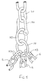
- a floating storage tanker 10 is anchored to the sea bed 12 by means of a three-leg anchor system comprising anchors 14a, 14b, 14c connected by risers 16a, 16b, 16c to a node 18, from which a mooring pendant 20 is secured to the tanker 10.
- the mooring is in the vicinity of a floating production platform (FPF) (not seen in the drawings) from which oil is transferred via a flowline.
- FPF floating production platform
- the flowline comprises a seabed portion 22 and a flexible riser 24.
- the riser 24 has a mid portion which is provided with flotation collars 26 and is restrained by a tether 28 secured to a clump weight 30.
- the mooring is set such that a 120° angle may be presented towards the FPF with the flowline approaching along the bisector of this angle. This geometry, together with the flotation of the collars 26 and the restraint by the tether 28 maintains the riser 24 clear of conflict with the mooring node 18.
- the upper part of the riser 24 is secured along the mooring pendant 20 by spaced double collars 32 and then taken aboard the tanker 10 via a chute assembly indicated at 34.
- Fig. 4 shows in more detail one suitable arrangement of the double collars 32.
- Each of the double collars 32 comprises a pair of pipe sections 321 joined by a rigid web 322 and having flared entry and exit sections 323, and may suitably be cast or fabricated in steel.
- the collars 32 can be spaced along the mooring pendant 20 and riser 24 by being hung on spacer chains 324.
- the anchors 14 may be any suitable form of conventional mooring anchor.
- Each of the anchor risers 16 has at least its on-bottom length constituted by chain. For water depths up to about 75 metres, the chain can be continuous to the node 18.
- wire In greater water depths up to about 150 metres, it is preferred to have the on-bottom section of chain but the catenary section of wire.
- the use of wire has several advantages. Principally, it reduces the weight which has to be lifted when the tanker is connecting to the system, as is discussed more fully below. It also makes the departure angle of the riser 16 from the node 18 nearer the horizontal, which increases the horizontal stability of the system, and simplifies stowage on the vessel used to deploy the system. Where wire is used for the catenary section, it is desirable to have the final 30 metres or so nearest the node 18 of chain, to reduce the risk of kinking of the wire.
- the wire may be replaced by synthetic fibre rope, for the same reasons.
- the node 18 may take any suitable form which connects together the three risers 16 and the pendant 20 with adequate mechanical strength.
- a suitably sized master ring may be used, or a triangular plate arrangement, together with conventional shackles. No swivel is incorporated in the node 18.
- node is shown in Fig. 5 in the form of a double ring 181, 182.
- the three risers 16 are connected by shackles 183 to the ring 181, and the pendant 20 is connected by a shackle 184 to the ring 182.
- buoyancy may be incorporated in the node 18 or in the anchor risers 16 adjacent the node 18.
- the tanker 10 is a segregated ballast tanker of 600,000 to 700,000 bbl capacity and the mooring is designed to hold the node 18 at a depth of 20 to 30 metres, and thus up to about 15 metres beneath the tanker hull.
- the mooring pendant 22 will require to be of the order of 40 to 50 metres in length.
- the preferred form for the mooring pendant 22 comprises a single large-size chain 36 extending from the node 18 and connected to a pair of chafe chains 38.
- the chains 38 For the same order of size of the tanker 10, it is suitable to have the chains 38 of 76 mm size, which will fit the standard OCIMF recommended tongue-type bow stoppers fitted to most tankers of this size. This arrangement simplifies the node design and minimises modification to the tanker.
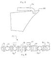
- FIGs. 6 and 7 there is shown a suitable tanker bow installation which requires a minimum of modification from standard shipping practice.
- Each of the chains 38 is held by a tongue-type bow stopper 40 raised above the foc'sle deck 42 on a seating 44.
- the incoming chain 38 passes through a fairlead 46 in the bow bulwark 48 aligned with the bow stopper 44, and the inboard end of the chain is passed to a winch windlass via a pedestal fairlead 50.
- the chute 34 is simple structure providing an arcuate guide on two axes for the flexible riser 24. It is not necessary to have any guidance for the riser 24 below bulwark level, since the riser will be spaced away from the remainder of the vessel's hull by the considerable flare of the foc'sle bulwarks in relation to the lower part of the hull.
- Fig. 7 also indicates the position on the foc'sle deck of valve gear generally designated at 52.
- the valve gear 52 is shown in more detail in Fig. 9, in which it will be seen that the flexible riser 25 is connected to a deck line 54 via a spool piece 56, a manually operated ball valve 58, a breakaway coupling 60, first and second hydraulically operated ball valves 62 and 64 between which is located a hydraulically operated emergency release collar 66, and an emergency shutdown valve 68.
- the breakaway coupling 60 is suitably a Gall-Thomson coupling which has bolts which shear at a predetermined axial load, the chute 34 ensuring that the load on the coupling is always axial.
- the Gall-Thomson coupling also includes a double-acting disc valve which seals both sides of the coupling as the unit breaks apart.
- the manually operated ball valve 58 would be used to close the connection in normal disconnection routines.
- the hydraulically activated release system comprising the components 62, 64, 66 can be operated remotely, for example, from the bridge of the vessel, where it is decided to make an emergency disconnection of the tanker.
- the emergency shutdown valve 68 is included to provide shutdown of flow without disconnection and would normally be part of the tanker's equipment even if not located close to the release system.
- the deck line 54 is most conveniently connected with the vessel tankage via the normal midships tank manifold, and thus the deck line 54 must extend from the bow area to the midships of the vessel.
- the line 54 can be provided in the form of steel tubing fixed to the conventional tube racking, or as a further length of hose of the same nature as the riser 24.
- the riser 24 must be a flexible hose with sufficient dynamic properties to accept movement of the ship's bow and movement of the touchdown point at the bottom of the catenary.
- a suitable hose is a fully bonded rubber hose, preferably "Manuli” hose of 6" or 8" size by Manuli Rubber Industries of Ascoli Piceno, Italy.
- the mooring arrangement of the present invention does not include a fluid swivel. There will therefore be a restriction on the number of turns the vessel can make, since turning full circle will effectively twist the fluid riser and the chafe chains round each other. Contrary to previous practice, the present inventors believe that this is not a real restriction in a floating production situation. It is believed that the weather patterns actually found in practice may make a vessel do complete turns, but there would be more than sufficient lighter weather periods when the vessel could be pulled back around to take a turn out.
- the embodiment described, using "Manuli" hose is capable of at least one and one-half turns, and up to three turns, without adversely affecting mechanical integrity and safety.
- the mooring system of the present invention allows a large tug to be dispensed with as the standby vessel, since the mooring system provides a redundant system in the event of a blackout, and the other roles could be filled by a much smaller vessel such as an AHTS (Anchor Handling/Tug/Supply) vessel.
- AHTS Anchor Handling/Tug/Supply
- each anchor would be laid using DGPS to a 10 metre tolerance. This has been achieved in depths in excess of 500 metres so is not anticipated a problem in any depth of less than 150 metres, even without European DGPS accuracy.
- each anchor is laid in turn, the cables run back to a common point; each cable as it is laid is buoyed off on a pendant wire. Insurance tensioning of the system can be done using the bollard pull of the tug.
- the anchor handler recovers all three cables over the stern roller. This requires a fairly large anchor handler with a winch of at least 250 tonne pull, and a bollard pull of about 150 tonnes. These are readily available in most areas of the world on the spot market.
- the node point is assembled and deployed over the side, lowering the node point to the seabed using the chafe chains, then their pendant wires, and finally polyprop rope. The main polyprop would then be buoyed off, a messenger attached and a marker buoy at the end of that.
- the support vessel When the tanker is coming on to location, the support vessel recovers the messenger, and passes it across to the tanker using a compressed air rocket gun. The tanker pulls in on the messengers, then the polyprop ropes, then the pendant wires, and starts to heave in the chafe chains, securing them in the bow stoppers.
- the windlasses to be used for this will require to be in good condition, and both to be operating at once. But the typical 40 tonne pull of ships' windlasses should be more than sufficient for this application, as the node point is only being brought to about 25 or 30 metres below the surface, and hence 10 to 15 metres below the ship's hull.
- Recovery of the system would be by chasing each of the anchor legs back to the anchor and lifting from that point; or alternatively to disconnect at the node point and heave in on the AHTS, working back to the anchor and lifting it up on deck.
- the present invention provides a mooring and flowline system which is of a surprisingly simplified nature in comparison with conventional systems for similar purposes and which uses simple, conventional, and readily available components in the novel manner.
- the application is equally applicable to other situations involving a mooring and a flowline, for example for mooring a floating production vessel and exporting its production via the flowline to some other facility.
- the system may also be used in supplying fuel products, for example to position a product tanker to supply fuel by flowline to a location ashore.
Description
- This invention relates to a mooring and flowline system for use in floating facilities for handling petroleum and petroleum products. The system is particularly, but not exclusively, applicable to the mooring and loading of floating export storage in production wells or wells undergoing extended well testing.
- Production from offshore wells was originally exported ashore by subsea pipeline, which requires a very large capital expenditure. More recently there has been a move to exploiting more marginal fields by the use of a floating production platform in conjunction with a floating storage facility from which oil is exported periodically by tanker. Commonly, the floating storage facility has been provided by conversion of an existing tanker. Such arrangements have worked well, but there is a continuing need for a substantial reduction in installation costs in order to improve the economics of marginal field production, and in order to make extended well testing more economically feasible.
- Tanker conversions used hitherto have required extensive conversion. In some cases a turret mooring is used which includes a rotary oil flowline joint, and this requires major structural work on the tanker in addition to the complex mooring turret. In other cases, a flexible riser to the tanker has been used but has required large quick connect-disconnect (QCDC) valves with a physical size and weight requiring installation outboard of the tanker bow on a specially installed and relatively large structure.
- An object of the present invention is to provide an improved mooring and flowline system which is simple and economical to install. It is also an object of the invention to provide a system which enables conventional tankers to be used as floating storage with a minimum of structural alteration.
- Accordingly, the present invention provides a mooring and flowline system comprising:
- means for mooring a floating storage and/or production vessel to the seabed, and a flowline for connection to a producing well or facility;
- the mooring means comprising at least two anchors in the sea bed, a respective anchor riser extending from each of the anchors, each of the anchor risers having one end secured to its anchor and the other end secured to a common mooring node member, and mooring pendant means extending from the node member for connection, in use, to the vessel;
- the flowline comprising a seabed flowline extending from the direction of the well or facility into the vicinity of the mooring means, and a flexible riser flowline extending from the seabed flowline to the vessel;
- and in which the flexible riser flowline is a continuous conduit without rotational couplings and has part of its length secured alongside at least part of the mooring pendant means.
-
- Preferably, there are at least three anchors in an angular array, three anchors at mutual 120° spacings being particularly preferred.
- The flowline riser is suitably held clear of the anchor risers and node member by providing a portion of the flowline riser with flotation and by tethering the same portion to restrict sideways movement.
- Preferably also, there is no swivel between the anchors and the vessel; the node member may be a plain ring, shackle or plate.
- The mooring pendant may comprise two parallel chains, one passing over each bow of the vessel.
- Preferably, the vessel is a tanker.
- In a particularly preferred form the invention, which allows a conventional tanker to be utilised as the storage vessel with a minimal amount of conversion, the parallel chains are brought inboard of the tanker to standard chain stoppers or to remotely controlled release stoppers, the flexible riser flowline is brought inboard of the tanker over a chute to have its inboard end lying along the tanker deck, and quick connect/disconnect valve means are located on the tanker deck between said flowline riser inboard end and a tank manifold of the tanker.
- An embodiment of the invention will now be described, by way of example, with reference to the drawings, in which:
- Fig. 1 is a schematic side view of one embodiment of the invention in use with a storage tanker;
- Fig. 2 is a plan view corresponding to Fig. 1;
- Fig. 3 is a view similar to Fig. 1 but showing the system out of use with the storage tanker removed;
- Fig. 4 shows a detail of the system of Figs. 1 to 3;
- Fig. 5 shows one form of node used in the system;
- Fig. 6 is a schematic side view of a tanker bow illustrating a suitable arrangement for use in present invention;
- Fig. 7 is a plan view corresponding to Fig. 6;
- Fig. 8 is a side view of a chute seen in Fig. 7; and
- Fig. 9 illustrates in more detail part of the oil line seen in Fig. 7.
-
- Referring particularly to Figs. 1 and 2, a
floating storage tanker 10 is anchored to thesea bed 12 by means of a three-leg anchorsystem comprising anchors risers 16a, 16b, 16c to anode 18, from which amooring pendant 20 is secured to thetanker 10. The mooring is in the vicinity of a floating production platform (FPF) (not seen in the drawings) from which oil is transferred via a flowline. - The flowline comprises a
seabed portion 22 and aflexible riser 24. Theriser 24 has a mid portion which is provided withflotation collars 26 and is restrained by atether 28 secured to aclump weight 30. As seen in Fig. 2, the mooring is set such that a 120° angle may be presented towards the FPF with the flowline approaching along the bisector of this angle. This geometry, together with the flotation of thecollars 26 and the restraint by thetether 28 maintains theriser 24 clear of conflict with themooring node 18. - The upper part of the
riser 24 is secured along themooring pendant 20 by spaceddouble collars 32 and then taken aboard thetanker 10 via a chute assembly indicated at 34. - Fig. 4 shows in more detail one suitable arrangement of the
double collars 32. Each of thedouble collars 32 comprises a pair ofpipe sections 321 joined by arigid web 322 and having flared entry andexit sections 323, and may suitably be cast or fabricated in steel. Thecollars 32 can be spaced along themooring pendant 20 andriser 24 by being hung onspacer chains 324. - The
anchors 14 may be any suitable form of conventional mooring anchor. Each of theanchor risers 16 has at least its on-bottom length constituted by chain. For water depths up to about 75 metres, the chain can be continuous to thenode 18. - In greater water depths up to about 150 metres, it is preferred to have the on-bottom section of chain but the catenary section of wire. The use of wire has several advantages. Principally, it reduces the weight which has to be lifted when the tanker is connecting to the system, as is discussed more fully below. It also makes the departure angle of the
riser 16 from thenode 18 nearer the horizontal, which increases the horizontal stability of the system, and simplifies stowage on the vessel used to deploy the system. Where wire is used for the catenary section, it is desirable to have the final 30 metres or so nearest thenode 18 of chain, to reduce the risk of kinking of the wire. - In water depths greater than about 150 metres, the wire may be replaced by synthetic fibre rope, for the same reasons.
- The
node 18 may take any suitable form which connects together the threerisers 16 and thependant 20 with adequate mechanical strength. A suitably sized master ring may be used, or a triangular plate arrangement, together with conventional shackles. No swivel is incorporated in thenode 18. - One example of node is shown in Fig. 5 in the form of a
double ring risers 16 are connected byshackles 183 to thering 181, and thependant 20 is connected by ashackle 184 to thering 182. - In some circumstances there may be an advantage in reducing the weight of the node and the catenary sections, and to this end buoyancy (not shown) may be incorporated in the
node 18 or in theanchor risers 16 adjacent thenode 18. - In a typical installation, the
tanker 10 is a segregated ballast tanker of 600,000 to 700,000 bbl capacity and the mooring is designed to hold thenode 18 at a depth of 20 to 30 metres, and thus up to about 15 metres beneath the tanker hull. In these circumstances, themooring pendant 22 will require to be of the order of 40 to 50 metres in length. - The preferred form for the
mooring pendant 22 comprises a single large-size chain 36 extending from thenode 18 and connected to a pair ofchafe chains 38. For the same order of size of thetanker 10, it is suitable to have thechains 38 of 76 mm size, which will fit the standard OCIMF recommended tongue-type bow stoppers fitted to most tankers of this size. This arrangement simplifies the node design and minimises modification to the tanker. - Referring to Figs. 6 and 7, there is shown a suitable tanker bow installation which requires a minimum of modification from standard shipping practice. Each of the
chains 38 is held by a tongue-type bow stopper 40 raised above thefoc'sle deck 42 on aseating 44. Theincoming chain 38 passes through a fairlead 46 in thebow bulwark 48 aligned with thebow stopper 44, and the inboard end of the chain is passed to a winch windlass via apedestal fairlead 50. - As will be seen from Figs 7 and 8 the
chute 34 is simple structure providing an arcuate guide on two axes for theflexible riser 24. It is not necessary to have any guidance for theriser 24 below bulwark level, since the riser will be spaced away from the remainder of the vessel's hull by the considerable flare of the foc'sle bulwarks in relation to the lower part of the hull. - Fig. 7 also indicates the position on the foc'sle deck of valve gear generally designated at 52. The
valve gear 52 is shown in more detail in Fig. 9, in which it will be seen that theflexible riser 25 is connected to adeck line 54 via aspool piece 56, a manually operatedball valve 58, abreakaway coupling 60, first and second hydraulically operatedball valves 62 and 64 between which is located a hydraulically operated emergency release collar 66, and anemergency shutdown valve 68. Thebreakaway coupling 60 is suitably a Gall-Thomson coupling which has bolts which shear at a predetermined axial load, thechute 34 ensuring that the load on the coupling is always axial. The Gall-Thomson coupling also includes a double-acting disc valve which seals both sides of the coupling as the unit breaks apart. The manually operatedball valve 58 would be used to close the connection in normal disconnection routines. The hydraulically activated release system comprising thecomponents 62, 64, 66 can be operated remotely, for example, from the bridge of the vessel, where it is decided to make an emergency disconnection of the tanker. Theemergency shutdown valve 68 is included to provide shutdown of flow without disconnection and would normally be part of the tanker's equipment even if not located close to the release system. - The
deck line 54 is most conveniently connected with the vessel tankage via the normal midships tank manifold, and thus thedeck line 54 must extend from the bow area to the midships of the vessel. Theline 54 can be provided in the form of steel tubing fixed to the conventional tube racking, or as a further length of hose of the same nature as theriser 24. - The
riser 24 must be a flexible hose with sufficient dynamic properties to accept movement of the ship's bow and movement of the touchdown point at the bottom of the catenary. A suitable hose is a fully bonded rubber hose, preferably "Manuli" hose of 6" or 8" size by Manuli Rubber Industries of Ascoli Piceno, Italy. - It will be appreciated from the foregoing description that the mooring arrangement of the present invention does not include a fluid swivel. There will therefore be a restriction on the number of turns the vessel can make, since turning full circle will effectively twist the fluid riser and the chafe chains round each other. Contrary to previous practice, the present inventors believe that this is not a real restriction in a floating production situation. It is believed that the weather patterns actually found in practice may make a vessel do complete turns, but there would be more than sufficient lighter weather periods when the vessel could be pulled back around to take a turn out. The embodiment described, using "Manuli" hose, is capable of at least one and one-half turns, and up to three turns, without adversely affecting mechanical integrity and safety.
- It is currently accepted practice to have a tug on permanent standby in these situations. This is for three main reasons: emergency towing if the tanker suffers a power blackout, support for the tanker when connecting and disconnecting, and as a guard vessel to stop passing fishing and other craft from going between the rig and the tanker.
- The mooring system of the present invention allows a large tug to be dispensed with as the standby vessel, since the mooring system provides a redundant system in the event of a blackout, and the other roles could be filled by a much smaller vessel such as an AHTS (Anchor Handling/Tug/Supply) vessel.
- Because it uses standard anchors and anchor cable, a normal anchor handling tug vessel can install the system. Initially each anchor would be laid using DGPS to a 10 metre tolerance. This has been achieved in depths in excess of 500 metres so is not anticipated a problem in any depth of less than 150 metres, even without European DGPS accuracy.
- Each anchor is laid in turn, the cables run back to a common point; each cable as it is laid is buoyed off on a pendant wire. Insurance tensioning of the system can be done using the bollard pull of the tug. When all three have been laid the anchor handler recovers all three cables over the stern roller. This requires a fairly large anchor handler with a winch of at least 250 tonne pull, and a bollard pull of about 150 tonnes. These are readily available in most areas of the world on the spot market. The node point is assembled and deployed over the side, lowering the node point to the seabed using the chafe chains, then their pendant wires, and finally polyprop rope. The main polyprop would then be buoyed off, a messenger attached and a marker buoy at the end of that.
- When the tanker is coming on to location, the support vessel recovers the messenger, and passes it across to the tanker using a compressed air rocket gun. The tanker pulls in on the messengers, then the polyprop ropes, then the pendant wires, and starts to heave in the chafe chains, securing them in the bow stoppers. The windlasses to be used for this will require to be in good condition, and both to be operating at once. But the typical 40 tonne pull of ships' windlasses should be more than sufficient for this application, as the node point is only being brought to about 25 or 30 metres below the surface, and hence 10 to 15 metres below the ship's hull.
- In the event of disconnection, it is no different from a tanker disconnecting from a buoy: release the chafe chains from the bow stoppers, and lower them over the bow as the vessel moves away. The assistance of a support tug on site would make this operation feasible even in bad weather, by providing control of the bow and using the ship's main engines to keep slack on the chafe chains for releasing from the tongues.
- Recovery of the system would be by chasing each of the anchor legs back to the anchor and lifting from that point; or alternatively to disconnect at the node point and heave in on the AHTS, working back to the anchor and lifting it up on deck.
- It will be seen that the present invention provides a mooring and flowline system which is of a surprisingly simplified nature in comparison with conventional systems for similar purposes and which uses simple, conventional, and readily available components in the novel manner.
- Although described with particular reference to the transfer of oil from a producing well to a storage vessel, the application is equally applicable to other situations involving a mooring and a flowline, for example for mooring a floating production vessel and exporting its production via the flowline to some other facility. The system may also be used in supplying fuel products, for example to position a product tanker to supply fuel by flowline to a location ashore.
Claims (14)
- A mooring and flowline system comprising:means (16a,16b)for mooring a floating (10)storage and/or production vessel to the seabed (12), and a flowline (24)for connection to a producing well or facility;the mooring means (16a,16b)comprising at least two anchors (14a,14b) in the sea bed, a respective anchor riser extending from each of the anchors, each of the anchor risers having one end secured to its anchor (14a,14b)and the other end secured to a common mooring node member(18), and mooring pendant means (20)extending from the node member for connection, in use, to the vessel(10);the flowline (24) comprising a seabed flowline (22)extending from the direction of the well or facility into the vicinity of the mooring means, and a flexible riser flowline (24)extending from the seabed flowline (22)to the vessel;and in which the flexible riser flowline (24)is a continuous conduit without rotational couplings and has part of its length secured alongside at least part of the mooring pendant means.
- A system according to claim 1, in which there are at least three anchors in an angular array.
- A system according to claim 2, in which there are three anchors at mutual 120° spacings.
- A system according to any preceding claim, in which the riser flowline is of fully bonded reinforced rubber construction.
- A system according to any preceding claim, in which a portion of the flowline riser is provided with flotation means, and in which a tether connects said portion to the seabed.
- A system according to any preceding claim, in which there is no swivel between the anchors and the vessel.
- A system according to claim 6, in which the node member comprises a plate or one or more plain rings or shackles.
- A system according to any preceding claim, in which the mooring pendant comprises two parallel chains, one passing over each bow of the vessel.
- A system according to claim 8, in which the vessel is a tanker.
- A system according to claim 9, in which the parallel chains are brought inboard of the tanker to standard chain stoppers or to remotely controlled release stoppers.
- A system according to claim 10, in which the flexible riser flowline is brought inboard of the tanker over a chute to have its inboard end lying along the tanker deck, and quick connect/disconnect valve means are located on the tanker deck between said flowline riser inboard end and a tank manifold of the tanker.
- A system according to claim 11, in which said valve means includes a self-sealing breakaway coupling.
- A vessel (10)for use in the system of claim 1, the vessel including stopper means (40)for releasably securing a mooring pendant(38), fairlead means (46)for receiving the mooring pendant (38)from outboard and guiding it to said stopper means(40), a petroleum conduit terminating in quick connect/disconnect valve means(52), and a chute (34)for receiving and guiding a flexible riser hose (24)disposed, in use, between said valve means (52)and a mooring pendant (38) outboard of said fairlead means(46).
- A vessel according to claim 13, said vessel being a tanker ship with said chute and valve means positioned on the foc'sle of the ship, and in which the fairlead means comprises port and starboard fairleads for a twin chain pendant and said stopper means comprises a pair of tongue-type stoppers.
Applications Claiming Priority (2)
| Application Number | Priority Date | Filing Date | Title |
|---|---|---|---|
| GB9504276A GB2296904B (en) | 1995-03-03 | 1995-03-03 | Mooring and Flowline System |
| GB9504276 | 1995-03-03 |
Publications (2)
| Publication Number | Publication Date |
|---|---|
| EP0729882A1 EP0729882A1 (en) | 1996-09-04 |
| EP0729882B1 true EP0729882B1 (en) | 1999-12-22 |
Family
ID=10770576
Family Applications (1)
| Application Number | Title | Priority Date | Filing Date |
|---|---|---|---|
| EP19960301381 Expired - Lifetime EP0729882B1 (en) | 1995-03-03 | 1996-03-01 | Mooring and flowline system |
Country Status (6)
| Country | Link |
|---|---|
| EP (1) | EP0729882B1 (en) |
| DE (1) | DE69605696D1 (en) |
| DK (1) | DK0729882T3 (en) |
| GB (1) | GB2296904B (en) |
| GR (1) | GR3033043T3 (en) |
| NO (1) | NO313453B1 (en) |
Families Citing this family (12)
| Publication number | Priority date | Publication date | Assignee | Title |
|---|---|---|---|---|
| NO303741B1 (en) * | 1996-03-28 | 1998-08-24 | Alcatel Kabel Norge As | Apparatus and method for anchoring a riser or the like |
| GB2330157B (en) * | 1997-10-07 | 2001-11-07 | Bluewater Terminal Systems Nv | Riser system for connecting a seabed installation with a floating vessel |
| GB2336143B (en) * | 1998-03-04 | 2002-03-13 | Victoria Oilfield Dev | Mooring system |
| US6200180B1 (en) | 1998-09-01 | 2001-03-13 | Nortrans Offshore (S) Pte Ltd | Mooring system for tanker vessels |
| GB0002703D0 (en) * | 2000-02-08 | 2000-03-29 | Victoria Oilfield Dev Limited | Mooring and flowline system |
| GB2387188B (en) * | 2002-04-04 | 2005-06-01 | Bluewater Terminal Systems Nv | Apparatus for attaching a fluid conduit to a structure |
| GB0421795D0 (en) | 2004-10-01 | 2004-11-03 | Baross John S | Full weathervaning bow mooring and riser inboarding assembly |
| US7793723B2 (en) | 2006-01-19 | 2010-09-14 | Single Buoy Moorings, Inc. | Submerged loading system |
| GB201114291D0 (en) | 2011-08-19 | 2011-10-05 | Axis ltd | Mooring system |
| CN103738477B (en) * | 2014-01-26 | 2017-02-08 | 中国海洋石油总公司 | Method for replacing upper anchor cable of mooring anchor legs |
| NO341536B1 (en) | 2016-02-23 | 2017-12-04 | Can Systems As | A marine riser and method for installation |
| CN106089108B (en) * | 2016-06-30 | 2018-01-09 | 西南石油大学 | A kind of vortex-induced vibration suppression device and method for draining injection destruction around laminar boundary layer |
Family Cites Families (8)
| Publication number | Priority date | Publication date | Assignee | Title |
|---|---|---|---|---|
| US3466680A (en) * | 1967-07-14 | 1969-09-16 | Air Logistics Corp | Apparatus for loading and unloading offshore vessels |
| GB1404775A (en) * | 1971-10-06 | 1975-09-03 | Exxon Production Research Co | Articulated riser |
| NL7206986A (en) * | 1972-05-24 | 1973-11-27 | ||
| FR2219053B3 (en) * | 1973-02-23 | 1976-02-20 | Cg Doris Fr | |
| US3863590A (en) * | 1974-01-14 | 1975-02-04 | Imodco | Automatic mooring system |
| FR2534545A1 (en) * | 1982-10-18 | 1984-04-20 | Loire Rene | SIMPLIFIED SIMPLIFYING DEVICE FOR MOORING AND LOADING OR UNLOADING TANK VESSELS FROM AN UNDERWATER SUPPLY OR FLUID EXHAUST DUCT AND METHOD FOR ESTABLISHING UNDERWATER DRIVING AND UNDERWATER DRIVING SIMPLIFIED MOORING DEVICE |
| US4645467A (en) * | 1984-04-24 | 1987-02-24 | Amtel, Inc. | Detachable mooring and cargo transfer system |
| EP0407662B2 (en) * | 1989-07-14 | 1999-06-23 | Single Buoy Moorings Inc. | Device for positioning of a buoy body |
-
1995
- 1995-03-03 GB GB9504276A patent/GB2296904B/en not_active Expired - Fee Related
-
1996
- 1996-03-01 DK DK96301381T patent/DK0729882T3/en active
- 1996-03-01 NO NO19960847A patent/NO313453B1/en not_active IP Right Cessation
- 1996-03-01 DE DE69605696T patent/DE69605696D1/en not_active Expired - Lifetime
- 1996-03-01 EP EP19960301381 patent/EP0729882B1/en not_active Expired - Lifetime
-
2000
- 2000-03-23 GR GR20000400729T patent/GR3033043T3/en not_active IP Right Cessation
Also Published As
| Publication number | Publication date |
|---|---|
| GB2296904A (en) | 1996-07-17 |
| NO313453B1 (en) | 2002-10-07 |
| GB2296904A8 (en) | 1996-07-21 |
| DE69605696D1 (en) | 2000-01-27 |
| GR3033043T3 (en) | 2000-08-31 |
| EP0729882A1 (en) | 1996-09-04 |
| GB2296904B (en) | 1996-12-18 |
| GB9504276D0 (en) | 1995-04-19 |
| DK0729882T3 (en) | 2000-06-13 |
| NO960847L (en) | 1996-09-04 |
| NO960847D0 (en) | 1996-03-01 |
| GB2296904A9 (en) | 1996-07-21 |
Similar Documents
| Publication | Publication Date | Title |
|---|---|---|
| US5944448A (en) | Oil field installation with mooring and flowline system | |
| US6435124B1 (en) | Mooring and flowline system | |
| EP1796958B1 (en) | Offshore vessel mooring and riser inboarding system | |
| JP5362819B2 (en) | Separable turret mooring system with rotatable turntable | |
| US6415828B1 (en) | Dual buoy single point mooring and fluid transfer system | |
| EP2744703B1 (en) | Mooring system and connector assembly | |
| CN109415106B (en) | Emergency stop system and method | |
| EP0729882B1 (en) | Mooring and flowline system | |
| AU686328B2 (en) | A vessel for production and/or loading/unloading and transport of hydrocarbons from offshore fields, and/or for carrying out well operations | |
| AU2010252013B2 (en) | Offshore structure and mooring arrangement | |
| Rutkowski | A comparison between conventional buoy mooring CBM, single point mooring SPM and single anchor loading sal systems considering the hydro-meteorological condition limits for safe ship’s operation offshore | |
| EP2398695B1 (en) | Deep water and ultra deep water mooring system | |
| CN117622381A (en) | Oilfield development facility with mooring and streamline system | |
| Prischi et al. | SS-offshore offloading systems and operations bonded flexible oil offloading lines, a cost effective alternative to traditional oil offloading lines | |
| GB2123775A (en) | Mooring ships | |
| Li et al. | Horizontal Installation of TLP Tendons | |
| Bensimon et al. | Deepwater Installation of a Large Capacity FPSO with Large Number of Risers in the Marlim Field | |
| GB1564755A (en) | Marine riser mooring apparatus | |
| GB2273694A (en) | Offshore loading system. | |
| AU2005203655A1 (en) | System for managing offshore drilled products | |
| IE44501B1 (en) | Marine riser mooring apparatus |
Legal Events
| Date | Code | Title | Description |
|---|---|---|---|
| PUAI | Public reference made under article 153(3) epc to a published international application that has entered the european phase |
Free format text: ORIGINAL CODE: 0009012 |
|
| AK | Designated contracting states |
Kind code of ref document: A1 Designated state(s): DE DK ES FI FR GB GR IE IT NL PT SE |
|
| AX | Request for extension of the european patent |
Free format text: LT;LV PAYMENT 960319 |
|
| RAX | Requested extension states of the european patent have changed |
Free format text: LT;LV PAYMENT 960319 |
|
| 17P | Request for examination filed |
Effective date: 19970304 |
|
| GRAG | Despatch of communication of intention to grant |
Free format text: ORIGINAL CODE: EPIDOS AGRA |
|
| 17Q | First examination report despatched |
Effective date: 19981117 |
|
| GRAG | Despatch of communication of intention to grant |
Free format text: ORIGINAL CODE: EPIDOS AGRA |
|
| GRAH | Despatch of communication of intention to grant a patent |
Free format text: ORIGINAL CODE: EPIDOS IGRA |
|
| GRAH | Despatch of communication of intention to grant a patent |
Free format text: ORIGINAL CODE: EPIDOS IGRA |
|
| GRAA | (expected) grant |
Free format text: ORIGINAL CODE: 0009210 |
|
| RAP1 | Party data changed (applicant data changed or rights of an application transferred) |
Owner name: VICTORIA OILFIELD DEVELOPMENT LIMITED |
|
| AK | Designated contracting states |
Kind code of ref document: B1 Designated state(s): DE DK ES FI FR GB GR IE IT NL PT SE |
|
| AX | Request for extension of the european patent |
Free format text: LV PAYMENT 19960319 |
|
| PG25 | Lapsed in a contracting state [announced via postgrant information from national office to epo] |
Ref country code: SE Free format text: THE PATENT HAS BEEN ANNULLED BY A DECISION OF A NATIONAL AUTHORITY Effective date: 19991222 Ref country code: FI Free format text: LAPSE BECAUSE OF FAILURE TO SUBMIT A TRANSLATION OF THE DESCRIPTION OR TO PAY THE FEE WITHIN THE PRESCRIBED TIME-LIMIT Effective date: 19991222 Ref country code: ES Free format text: THE PATENT HAS BEEN ANNULLED BY A DECISION OF A NATIONAL AUTHORITY Effective date: 19991222 |
|
| REF | Corresponds to: |
Ref document number: 69605696 Country of ref document: DE Date of ref document: 20000127 |
|
| PG25 | Lapsed in a contracting state [announced via postgrant information from national office to epo] |
Ref country code: IE Free format text: LAPSE BECAUSE OF NON-PAYMENT OF DUE FEES Effective date: 20000301 |
|
| REG | Reference to a national code |
Ref country code: IE Ref legal event code: FG4D |
|
| ITF | It: translation for a ep patent filed |
Owner name: UFFICIO BREVETTI RAPISARDI S.R.L. |
|
| PG25 | Lapsed in a contracting state [announced via postgrant information from national office to epo] |
Ref country code: PT Free format text: LAPSE BECAUSE OF FAILURE TO SUBMIT A TRANSLATION OF THE DESCRIPTION OR TO PAY THE FEE WITHIN THE PRESCRIBED TIME-LIMIT Effective date: 20000322 Ref country code: GB Free format text: LAPSE BECAUSE OF NON-PAYMENT OF DUE FEES Effective date: 20000322 |
|
| PG25 | Lapsed in a contracting state [announced via postgrant information from national office to epo] |
Ref country code: DE Free format text: LAPSE BECAUSE OF FAILURE TO SUBMIT A TRANSLATION OF THE DESCRIPTION OR TO PAY THE FEE WITHIN THE PRESCRIBED TIME-LIMIT Effective date: 20000323 |
|
| ET | Fr: translation filed | ||
| REG | Reference to a national code |
Ref country code: DK Ref legal event code: T3 |
|
| PLBE | No opposition filed within time limit |
Free format text: ORIGINAL CODE: 0009261 |
|
| STAA | Information on the status of an ep patent application or granted ep patent |
Free format text: STATUS: NO OPPOSITION FILED WITHIN TIME LIMIT |
|
| GBPC | Gb: european patent ceased through non-payment of renewal fee |
Effective date: 20000322 |
|
| 26N | No opposition filed | ||
| REG | Reference to a national code |
Ref country code: IE Ref legal event code: MM4A |
|
| NLS | Nl: assignments of ep-patents |
Owner name: BROVIG RDS LIMITED;BROVIG PRODUCTION SERVICES LIMI |
|
| REG | Reference to a national code |
Ref country code: FR Ref legal event code: TP Ref country code: FR Ref legal event code: CL |
|
| REG | Reference to a national code |
Ref country code: FR Ref legal event code: TP |
|
| NLT1 | Nl: modifications of names registered in virtue of documents presented to the patent office pursuant to art. 16 a, paragraph 1 |
Owner name: CRYSTAL PRODUCTION UK LIMITED Owner name: BROVIG UK LIMITED |
|
| NLUE | Nl: licence registered with regard to european patents |
Effective date: 20030728 |
|
| REG | Reference to a national code |
Ref country code: FR Ref legal event code: TP Ref country code: FR Ref legal event code: RL Ref country code: FR Ref legal event code: CL Ref country code: FR Ref legal event code: CD Ref country code: FR Ref legal event code: AU |
|
| REG | Reference to a national code |
Ref country code: FR Ref legal event code: TP Ref country code: FR Ref legal event code: CD |
|
| NLS | Nl: assignments of ep-patents |
Owner name: FIRST TECH LIMITED Effective date: 20050928 |
|
| NLT1 | Nl: modifications of names registered in virtue of documents presented to the patent office pursuant to art. 16 a, paragraph 1 |
Owner name: MOORING SYSTEMS LIMITED |
|
| NLUE | Nl: licence registered with regard to european patents |
Effective date: 20050928 |
|
| PGFP | Annual fee paid to national office [announced via postgrant information from national office to epo] |
Ref country code: DK Payment date: 20080221 Year of fee payment: 13 |
|
| PGFP | Annual fee paid to national office [announced via postgrant information from national office to epo] |
Ref country code: NL Payment date: 20080225 Year of fee payment: 13 |
|
| PGFP | Annual fee paid to national office [announced via postgrant information from national office to epo] |
Ref country code: FR Payment date: 20080219 Year of fee payment: 13 |
|
| PGFP | Annual fee paid to national office [announced via postgrant information from national office to epo] |
Ref country code: GR Payment date: 20080228 Year of fee payment: 13 |
|
| REG | Reference to a national code |
Ref country code: DK Ref legal event code: EBP |
|
| NLV4 | Nl: lapsed or anulled due to non-payment of the annual fee |
Effective date: 20091001 |
|
| REG | Reference to a national code |
Ref country code: FR Ref legal event code: ST Effective date: 20091130 |
|
| PG25 | Lapsed in a contracting state [announced via postgrant information from national office to epo] |
Ref country code: NL Free format text: LAPSE BECAUSE OF NON-PAYMENT OF DUE FEES Effective date: 20091001 |
|
| PG25 | Lapsed in a contracting state [announced via postgrant information from national office to epo] |
Ref country code: FR Free format text: LAPSE BECAUSE OF NON-PAYMENT OF DUE FEES Effective date: 20091123 Ref country code: DK Free format text: LAPSE BECAUSE OF NON-PAYMENT OF DUE FEES Effective date: 20090331 |
|
| PG25 | Lapsed in a contracting state [announced via postgrant information from national office to epo] |
Ref country code: GR Free format text: LAPSE BECAUSE OF NON-PAYMENT OF DUE FEES Effective date: 20091002 |
|
| PG25 | Lapsed in a contracting state [announced via postgrant information from national office to epo] |
Ref country code: IT Free format text: LAPSE BECAUSE OF NON-PAYMENT OF DUE FEES Effective date: 20100301 |
|
| PGRI | Patent reinstated in contracting state [announced from national office to epo] |
Ref country code: IT Effective date: 20110616 |
|
| PGFP | Annual fee paid to national office [announced via postgrant information from national office to epo] |
Ref country code: IT Payment date: 20120327 Year of fee payment: 17 |
|
| PG25 | Lapsed in a contracting state [announced via postgrant information from national office to epo] |
Ref country code: IT Free format text: LAPSE BECAUSE OF NON-PAYMENT OF DUE FEES Effective date: 20140301 |