EP0729827A1 - Thin mesh, manufacturing method thereof and manufacturing device therefor - Google Patents
Thin mesh, manufacturing method thereof and manufacturing device therefor Download PDFInfo
- Publication number
- EP0729827A1 EP0729827A1 EP94913775A EP94913775A EP0729827A1 EP 0729827 A1 EP0729827 A1 EP 0729827A1 EP 94913775 A EP94913775 A EP 94913775A EP 94913775 A EP94913775 A EP 94913775A EP 0729827 A1 EP0729827 A1 EP 0729827A1
- Authority
- EP
- European Patent Office
- Prior art keywords
- holes
- aforesaid
- thin
- mesh
- produce
- Prior art date
- Legal status (The legal status is an assumption and is not a legal conclusion. Google has not performed a legal analysis and makes no representation as to the accuracy of the status listed.)
- Granted
Links
Images


Classifications
-
- B—PERFORMING OPERATIONS; TRANSPORTING
- B23—MACHINE TOOLS; METAL-WORKING NOT OTHERWISE PROVIDED FOR
- B23K—SOLDERING OR UNSOLDERING; WELDING; CLADDING OR PLATING BY SOLDERING OR WELDING; CUTTING BY APPLYING HEAT LOCALLY, e.g. FLAME CUTTING; WORKING BY LASER BEAM
- B23K26/00—Working by laser beam, e.g. welding, cutting or boring
- B23K26/02—Positioning or observing the workpiece, e.g. with respect to the point of impact; Aligning, aiming or focusing the laser beam
- B23K26/06—Shaping the laser beam, e.g. by masks or multi-focusing
- B23K26/064—Shaping the laser beam, e.g. by masks or multi-focusing by means of optical elements, e.g. lenses, mirrors or prisms
- B23K26/066—Shaping the laser beam, e.g. by masks or multi-focusing by means of optical elements, e.g. lenses, mirrors or prisms by using masks
-
- B—PERFORMING OPERATIONS; TRANSPORTING
- B23—MACHINE TOOLS; METAL-WORKING NOT OTHERWISE PROVIDED FOR
- B23K—SOLDERING OR UNSOLDERING; WELDING; CLADDING OR PLATING BY SOLDERING OR WELDING; CUTTING BY APPLYING HEAT LOCALLY, e.g. FLAME CUTTING; WORKING BY LASER BEAM
- B23K26/00—Working by laser beam, e.g. welding, cutting or boring
- B23K26/08—Devices involving relative movement between laser beam and workpiece
- B23K26/0823—Devices involving rotation of the workpiece
-
- B—PERFORMING OPERATIONS; TRANSPORTING
- B23—MACHINE TOOLS; METAL-WORKING NOT OTHERWISE PROVIDED FOR
- B23K—SOLDERING OR UNSOLDERING; WELDING; CLADDING OR PLATING BY SOLDERING OR WELDING; CUTTING BY APPLYING HEAT LOCALLY, e.g. FLAME CUTTING; WORKING BY LASER BEAM
- B23K26/00—Working by laser beam, e.g. welding, cutting or boring
- B23K26/36—Removing material
- B23K26/38—Removing material by boring or cutting
- B23K26/382—Removing material by boring or cutting by boring
- B23K26/384—Removing material by boring or cutting by boring of specially shaped holes
-
- B—PERFORMING OPERATIONS; TRANSPORTING
- B23—MACHINE TOOLS; METAL-WORKING NOT OTHERWISE PROVIDED FOR
- B23K—SOLDERING OR UNSOLDERING; WELDING; CLADDING OR PLATING BY SOLDERING OR WELDING; CUTTING BY APPLYING HEAT LOCALLY, e.g. FLAME CUTTING; WORKING BY LASER BEAM
- B23K26/00—Working by laser beam, e.g. welding, cutting or boring
- B23K26/36—Removing material
- B23K26/38—Removing material by boring or cutting
- B23K26/382—Removing material by boring or cutting by boring
- B23K26/389—Removing material by boring or cutting by boring of fluid openings, e.g. nozzles, jets
-
- B—PERFORMING OPERATIONS; TRANSPORTING
- B23—MACHINE TOOLS; METAL-WORKING NOT OTHERWISE PROVIDED FOR
- B23K—SOLDERING OR UNSOLDERING; WELDING; CLADDING OR PLATING BY SOLDERING OR WELDING; CUTTING BY APPLYING HEAT LOCALLY, e.g. FLAME CUTTING; WORKING BY LASER BEAM
- B23K2103/00—Materials to be soldered, welded or cut
- B23K2103/30—Organic material
- B23K2103/42—Plastics
-
- B—PERFORMING OPERATIONS; TRANSPORTING
- B23—MACHINE TOOLS; METAL-WORKING NOT OTHERWISE PROVIDED FOR
- B23K—SOLDERING OR UNSOLDERING; WELDING; CLADDING OR PLATING BY SOLDERING OR WELDING; CUTTING BY APPLYING HEAT LOCALLY, e.g. FLAME CUTTING; WORKING BY LASER BEAM
- B23K2103/00—Materials to be soldered, welded or cut
- B23K2103/50—Inorganic material, e.g. metals, not provided for in B23K2103/02 – B23K2103/26
Definitions
- This invention concerns a thin mesh and a method and device for producing that mesh. More specifically, it concerns a thin mesh produced by a high-density microscopic mesh process, a method for producing such a thin mesh using an ultraviolet beam, and a device for producing such a thin mesh.
- FIG 26 is a simplified cross section of a common design for an inhaler (atomizer) 101, which creates a spray by means of ultrasonic vibration.
- inhaler 101 Fixed to the upper portion of casing 104, inhaler 101 has a mesh 102 containing numerous microscopic holes 103, as pictured in Figure 27.
- the upper surface of the mushroom-shaped vibrator 105 is pressed against the lower surface of mesh 102, and the bottom of vibrator 105 is immersed in liquid medicine 107, which is kept in reservoir 106.
- suction tube 108 In the center of vibrator 105 and traversing its length.
- the mesh 102 which is used in the inhaler 101 described above, requires that medicine 107 be atomized (i.e., vaporized), the numerous holes 103 which constitute the mesh must be sufficiently minute, as shown in Figure 27. For this reason, the material used for the mesh must be exceedingly tough and resistant to corrosion. In addition, because of the use to which it will be put, a medical device such as inhaler 101 must use a material which is resistant to chemicals and safe for humans.
- Methods to produce a mesh 102 with microscopic holes 103 using a single process include electroforming, etching and the electron discharge method.
- mesh 102 is to be produced by electroforming, only certain specific metals such as nickel can be used, resulting in poor anti-corrosive properties. (Gold and some other metals could also be used, however these are expensive.) Since heavy metals pose a safety risk for humans, a mesh 102 made from nickel could not be used in medical equipment, and its uses are limited. A mesh which is safe for human beings can he achieved by plating the surface of nickel mesh 102 with another metal. However, since it is impossible to completely eliminate the formation of pinholes in the metal plating, it is not possible to completely prevent leaching of the nickel.
- the effective delivery of the drug to the affected part varies with the diameter of the particles of spray. This diameter is profoundly influenced by the shape and the cross-sectional contour of the holes 103 in the mesh. Because the mesh 102 in an inhaler 100 as described above must resonate with vibrator 105, the thickness of the mesh is constrained by the frequency of vibrator 105.
- both the arrangement of holes 103 and their shape must be regular, as shown in Figure 27; an irregular arrangement of holes 103 is not a possible design.
- This invention is developed in view of the shortcomings of the examples of the prior art discussed above. Its objective is to provide a mesh and a production technology for that mesh which would not be limited as to materials, provided the materials are thin enough This mesh would be able to use a material with superior anti-corrosive properties and chemical resistance, yet which would be safe for human beings. The shape of the holes in this mesh and their cross-sectional contour could be selected as needed.
- the thin mesh of this invention is distinguished by the fact that it has numerous microscopic through holes of high aspect ratio which are formed in a thin material by projecting a beam of ultraviolet light onto it.
- Materials which can be used for the mesh include polymers, ceramics and metal films.
- the method for producing a thin mesh according to this invention is distinguished by the fact that it entails creating numerous microscopic through holes in a thin material by projecting a beam of ultraviolet light onto it.
- the device for producing a thin mesh according to this invention is distinguished by the fact that it has a device for producing beams of ultraviolet light, which are sufficiently small, to produce through holes of the desired shape, and a device to move the thin material which is being processed and the aforesaid ultraviolet beams with respect to each other.
- the device for producing a thin mesh described above may be equipped with: a device to project beams of ultraviolet light, which are sufficiently small, to produce through holes of the desired shape; a device to store the shape into which the aforesaid through holes are to be formed; a device to move the thin material which is being processed and the aforesaid ultraviolet beams relative to each other; a device on the aforesaid moving device to detect the locations to be processed; a device to compare the signal from the aforesaid device to detect the locations to be processed with the shape into which the mesh is to be formed which is stored in the aforesaid storage device; and a device which, based on the comparison made by the above comparing device, controls the aforesaid moving device according to the shape to be formed and outputs to the aforesaid emitting device a signal causing it to oscillate the ultraviolet beams and a signal to control the intensity of those beams.
- Another method to produce a thin mesh according to this invention is distinguished by the fact that a series of masks are used, each of which provides a pattern of holes which differ from those of the next pattern in shape or diameter. These patterns are applied sequentially to the same region of the thin material and each is irradiated with an ultraviolet beam in order to create in the thin material through holes with the desired cross-sectional shape.
- Yet another device to produce a thin mesh according to this invention is distinguished by the fact that it is equipped with: a series of masks, each of which has a pattern of holes with the same pitch but which differ from those of the next mask in shape or diameter; a device to emit and focus simultaneously on the thin material the ultraviolet beams which pass through the pattern of holes in each of the aforesaid masks; and a device to move the thin material at a fixed pitch each time.
- This device to produce a thin mesh may also have a device to cut the aforesaid thin material in which holes have been formed.
- Yet another method to produce a thin mesh according to this invention is distinguished by the fact that it entails using beams of ultraviolet light to project onto a thin material the image of the pattern of holes in a mask and then varying the position of the thin material with respect to the plane on which the aforesaid image is focused, along a path which is parallel to the optical axis or the ultraviolet beams. In this way holes can be created in the thin material whose diameter varies with their depth.
- Yet another device to produce a thin mesh according to this invention is distinguished by the fact that it contains a device to generate beams of ultraviolet light; masks with patterns of holes in them; an optical system which can project onto the thin material, which is to be processed, the image of each of the aforesaid patterns of holes and which is capable of varying its magnification; and a translating device to move the aforesaid thin material on a path which is parallel to the optical axis of the ultraviolet beams.
- Yet another method to produce a thin mesh according to this invention is distinguished by the fact that it entails overlaying at least two submasks containing openings, matching up the aforesaid openings to create a pattern of holes, and varying slightly the overlap of the aforesaid holes so as to vary the dimensions of the holes in the aforesaid pattern.
- beams of ultraviolet light are passed through the aforesaid pattern of holes, through holes are created in the thin material.
- Yet another device to produce a thin mesh is distinguished by the fact that it has a device to generate beams of ultraviolet light; a mask consisting of at least two overlaid submasks containing openings whose dimensions can be varied by varying slightly the way in which the aforesaid submasks overlap; a device to vary the amount of overlap of the aforesaid submasks; and an optical system to project onto the thin material, which is to be processed, beams of ultraviolet light which have passed through the aforesaid pattern of holes.
- the material used to produce the thin mesh of this invention is a thin material.
- Thin polymer materials, thin ceramics or anti-corrosive and chemically resistant thin metal films can be used, resulting in a flexible mesh with superior resistance to corrosion and chemicals.
- a material composed of various substances can also be used. The most appropriate material can be selected for each application.
- the mesh is to be used in medical equipment, for example, it can be made from a material such as polysulfone or polyester which is safe to humans and offers superior resistance to corrosion and chemicals.
- the mesh can be made from a material such as polyamide.
- the method for producing a thin mesh In the method for producing a thin mesh according to this invention, beams of ultraviolet light are projected onto a thin material to create microscopic through holes.
- This method allows a microscopic mesh to be produced from whatever material one selects.
- holes are created by projecting beams of ultraviolet light of sufficiently small diameter with respect to the shape the holes are to attain, and the beans and the thin material are moved relative to each other, through holes of the desired shape can be created merely by scanning the beams, without having to rely on masks to shape the beams. This method eliminates the time required to change the mask. If a number of ultraviolet beams are used, a number of through holes can be formed at once, resulting in yet shorter processing time.
- a signal representing a detected location which is output by the device for that purpose in the moving device which moves the thin material can be compared with the projected appearance which is recorded in the device where the shape of the through holes are stored, and the moving device which moves the thin material can be controlled in response to this.
- a signal to oscillate the beams and a signal to adjust their intensity according to the shape of hole being produced in the material can be output to the device which projects the ultraviolet light. If this method is employed, the manufacture of a thin mesh having the desired type of holes can be automated.
- the focal plane of the ultraviolet beam and the thin material are varied with respect to each other along a path parallel to the optical axis of the beam, the degree to which the beam is defocused can be varied, and the area of the thin material onto which the beam is projected can be varied. If the distance from the focal plane to the thin material is varied continuously over time, the diameter of the holes can be varied continuously and smoothly along their depth. Tapered through holes whose inner surfaces vary smoothly can easily be produced. Use of this method will also result in a shorter processing time.
- a mask can be formed by overlaying at least two sub-masks with a number of openings in them, and a pattern of holes can be created by overlapping the openings. Then by varying the amount of overlap of the aforesaid openings, we can change the dimensions of the holes in the pattern. When we change the amount of overlap of the submasks, we can change the size of the holes. With this method, then, we can vary the size of the holes in the pattern using only a single mask and without changing the mask or adjusting the optical system. In this way we can produce through holes of various dimensions. If we vary the size of the holes in the pattern while the through holes are being created, we cause the diameter of the through holes to vary. This method allows us to create, in a short time, through holes with the desired cross-sectional contour whose diameters vary along their depth either continuously or non-continuously.
- Figure 1 uses an preferred embodiment of this invention to illustrate the basic principle which underlies this method to produce a mesh.
- Figures 2 (a) and (b) are perspective drawings showing a method to produce a thin mesh which is another preferred embodiment of this invention.
- Figure 3 is a rough drawing showing the configuration of a device to produce a thin mesh which is another preferred embodiment of this invention.
- Figure 4 is a perspective drawing illustrating the method to produce a thin mesh using the same device.
- Figure 5 is a plan view of a mesh produced by the same device.
- Figure 6 is a plan view of another mesh produced by the same device.
- Figure 7 illustrates a method to produce mesh holes using the same device.
- (a) shows a cross section of the desired hole;
- (b) shows a cross section of a similar mesh hole created by stepping the sides;
- (c) illustrates how the machining is done.
- Figure 8 shows another method for producing a mesh which is an preferred embodiment of this invention.
- Figure 9 shows the configuration of a device to produce a thin mesh which is another preferred embodiment of this invention.
- Figures 10 (a) and (b) are plan views of masks used in the same device to produce a thin mesh.
- Figure 11 is a rough perspective drawing of an excimer laser beam from the same device projected onto a piece of thin material.
- Figures 12 (a), (b) and (c) are cross sections illustrating the production method used in the same embodiment.
- (d) is a cross section of a finished mesh hole.
- Figure 13 shows the configuration of a device to produce a mesh which is another preferred embodiment of this invention.
- Figure 14 shows an example of a projection optics system which could be used in the same device.
- Figures 15 (a) and (b) show the relationship between the position (the degree of defocus) of the image and its dimensions in the same device to produce a mesh.
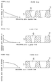
- Figure 16 (a) shows one way in which the degree of defocus can be varied over time; (b) is a cross section of holes produced by varying the defocus as shown in (a).
- Figure 17 (a) shows another way in which the degree of defocus can be varied over time; (b) is a cross section of holes produced by varying the defocus as shown in (a).
- Figure 18 (a) shows yet another way in which the degree of defocus can be varied over time; (b) is a cross section of holes produced by varying the defocus as shown in (a).
- Figure 19 shows the configuration of a device to produce a mesh which is another preferred embodiment of this invention.
- Figure 20 shows a front view of the submasks comprising the mask in the same device.
- Figures 21 (a), (b) and (c) show how the openings in that same mask vary.
- Figure 22 is a front view of the device to drive the mask which is used in the same device to produce a mesh.
- Figures 23 (a), (b), (c) and (d) are cross sections to illustrate the order in which the holes are machined by the same device to produce a mesh.
- Figures 24 (a), (b), (c) and (d) are cross sections illustrating a different order in which the holes may be machined by the same device to produce a mesh.
- Figure 25 is a front view of another device to drive a mask which may be used in the device to produce a mesh shown in Figure 19.
- Figure 26 is a cross section of an inhaler.
- Figure 27 is an enlarged plan view of a portion of the mesh used in the aforesaid inhaler.
- Figure 28 is a cross section of holes produced by electroforming.
- Figure 29 is a cross section of holes produced by etching or by the electron discharge method.
- Figure 1 uses an preferred embodiment of this invention to illustrate the basic principle which underlies this method to produce a mesh consisting of a thin material.
- Excimer laser beams L which are emitted by an excimer laser oscillator, pass through microscopic openings 2 in mask 1 and are thereby forced to assume a specified shape.
- the beams are then focused by objective lens 3 and projected onto thin material (i.e., mesh material) 5, consisting of, for example, a polymer such as polysulfone, polyester, or polyamide, which is immobilized on work stage 4, an XY table or the like.
- the reduced image of the pattern of holes 2 in mask 1 is caused to appear on thin material 5.
- holes 6, which are identical to those of pattern 2 in mask 1, at any desired magnification M.
- a mask 1 with numerous holes comprising a pattern 2, as shown in Figure 1, will create numerous holes 6 at a single time.
- Figures 2 (a) and (b) are partial elevation views illustrating another method for producing a thin mesh which is an preferred embodiment of this invention.
- metal foil 8 is affixed to the top of work stage 4.
- Master mask 10 has a single opening 9, which is created by etching or some similar process.
- Mask 10 shapes excimer laser beam L.
- Work stage 4 moves metal foil 8 while a pattern of holes 2 arranged in identical fashion to holes 6 in the previous mask 1 is created in metal foil 8 using excimer laser beam L.
- the mask 1 produced in this way is set on a mask stage, as shown in Figure 2 (b), and a piece of thin material 5, which may be polyamide or some similar substance, is affixed to work stage 4.
- This method allows us to manufacture a thin mesh 7 containing numerous holes 6 starting with master mask 1, which has only one relatively rough opening.
- FIG. 3 illustrates the configuration of device 11, which produces a mesh according to this invention.
- 12 is an excimer laser oscillator
- 13 is a mask stage which supports mask 1 and adjusts its position
- 14 is a projection optics system
- 15 is a totally reflective mirror
- 16 is an objective which creates an image of pattern 2 on the surface of material 5.
- 17 is a work stage such as an X-Y or R- ⁇ stage to move material 5, which is loaded upon it, in two dimensions with respect to excimer laser beams L
- 18 is a drive circuit which uses numerical values to control the speed, position, and so forth of work stage 17.
- Work stage 17 has an encoder or other device (not pictured) to detect the position of the work 19 is a device (a computer) to control the driving of the work stage.
- the computer has a storage device 20, which may be a floppy or hard disk drive to store the desired appearance of the holes 6 one wishes to create.
- the computer compares the signal representing the detected position of the work which is output by the device for that purpose with the desired appearance stored in device 20 and evaluates how well they match. Based on this evaluation, it outputs to drive circuit 18 a signal representing the target position for work stage 17. It also outputs to laser oscillator 12 a signal to adjust the intensity of the laser beam and a signal to begin oscillation. 21 is a display.
- the excimer laser beam L emitted by laser oscillator 12 is shaped into the desired beam pattern by mask 1 and passes through projection optics system 14.
- the beams are reflected by totally reflective mirror 15 and pass through objective 16 to strike material 5 on work stage 17.
- mask stage 13 has adjusted the position of mask 1, and the focal length of optical system 14 has been adjusted.
- the size of holes 2 in mask 1 is adjusted by imaging them on the surface of material 5 at different magnifications M.
- control device 19 causes drive circuit 18 to move work stage 17 over a path which is previously programmed. At the same time, it synchronously controls the oscillation of laser oscillator 12 to produce the desired holes in material 5.
- This type of device 11 can produce, for example, a mesh 7 like that shown in Figure 4.
- a mask 1 fashioned with the help of a master mask 10 is placed in mask stage 13, and material 5 is placed on work stage 17.
- Control device 19 causes work stage 17 to be moved continuously in a circular pattern according to the shape for holes 6 which is stored in device 20, and a number of holes 6 arranged in a desired pattern are produced at one time by excimer laser beams L, which are smaller in diameter than the holes they are creating.
- mask 1 need not be changed each time the shape of holes 6 needs to be modified.
- a pattern of holes 6 of any desired shape can be created simply by recording in device 20 the shape the holes are to be given and the path over which work stage 17 is to be moved.
- This method is not limited to the creation of round holes in a regular formation, as shown in Figure 26. It can also produce an irregular arrangement of holes 6 like that shown in Figure 5. To achieve this, one could either create a mask 1 with an irregular array of holes, or create holes 6 one at a time in an irregular pattern. Using a mask 1 with an irregular pattern 2 would allow us to produce a mesh 7 with holes of different sizes, as shown in Figure 5. Oddly shaped holes 6 such as those pictured in Figure 6 could also be created, either by producing a mask 1 with a pattern 2 of holes shaped like holes 6 in Figure 6, or by scanning an excimer laser beam L along the edge of each hole 6 in Figure 6.
- Figures 7 (a), (b) and (c) are cross sections of holes which illustrate other examples of methods for producing holes 6 using the device 11 pictured in Figure 3.
- Figure 7 (a) is a cross section of preferred hole 22, the desired outcome. Hole 22 is rotationally symmetric with respect to axis P. Its edge is a smoothly curved surface. This type of symmetric hole 22 can be created by projecting an excimer laser beam L onto material 5 while moving work stage 17 along a path comprising a series of concentric circles. If the machining depth is changed at every radius r, a hole 6 of any desired cross section can be produced.
- Figure 7 (c) illustrates this machining process.
- Excimer laser beam L is moved while it is tracing concentric circles within a single stationary hole 6 to create a circular hole in material 5.
- the depth of machining is determined by N, the number of revolutions of work stage 17 while excimer laser beam L is emitted. (If v is the linear velocity in the circumferential direction, the period during which laser beam L is emitted is proportional to N/v.
- control device 19 can at once create a number of holes 6 of the appearance shown in Figure 7 (b).
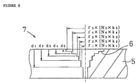
- Figure 8 shows another method to produce a mesh which is an preferred embodiment of this invention.
- excimer laser beam L is scanned over a circular path relative to material 5
- the beams L overlap differently on the inner and outer scanning paths.
- the effective energy intensity of beam L on the inner paths is greater than that on the outer paths. Since the way the beams overlap varies with the machining radius r, the average effective energy intensity of beam L will vary with machining radius r from the innermost to the outermost path even though the intensity of the beam L projected by laser oscillator 12 does not vary.
- d A (N ⁇ k) where A is a proportional constant.
- control device 19 can at once create a number of holes 6 of the appearance shown in Figure 8.
- beam intensity coefficient k we can accurately control machining depth d to produce holes 6 with precision contours.
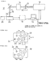
- Figure 9 shows the configuration of device 31, another preferred embodiment of a device to produce a mesh according to this invention.
- device 31, 12 is an excimer laser oscillator
- 13 is a mask stage to support and adjust the position of mask 32
- 14 is a projection optics system
- 15 is a totally reflective mirror
- 16 is an objective. All of these components have the same configuration and capability as those in device 11 pictured in Figure 3.
- Mask 32 which is placed in the aforesaid mask stage 13, has a number of holes 2a, 2b, and so forth, all having the same pitch.
- the mask 32 shown in Figure 10 (a) for example, has holes 2a, 2b and 2c arrayed in a single line. Each has a different diameter, but the pitch PM from center to center is constant.
- two sets of holes 2a, 2b and 2c are provided which are offset from each other by amounts X off and Y off in directions X and Y. It would also be acceptable to use a single set of holes or three or more sets offset from each other by a certain amount.
- Another alternative would be to have a pattern of holes 2a, 2b and 2c of different shapes, such as a circle, a square and a triangle, as shown in Figure 10 (b), formed successively in a single row at a single pitch PM.
- 34 is a feeding device to move a rolled or long piece of material 33 repeatedly at a fixed pitch
- 35 is a cutting device such as a laser cutter to cut material 33 into fixed lengths or shapes once holes 6 have been formed in it.
- 18 is a drive circuit to control the rate or the timing at which material 33 is fed.
- 19 is a control circuit to coordinate drive circuit 18 and laser oscillator 12 so that laser beam L is emitted synchronously with the timing at which material 33 is fed.
- Excimer laser beam L which is emitted by laser oscillator 12, passes through holes 2a, 2b and 2c, of various dimensions and shapes, in mask 32, which is fixed in mask stage 13.
- Laser beam L assumes shapes which are informed by the shapes of the holes in the mask, and these shaped beams strike optical system 14.
- Shaped beams L travel through optical system 14, are reflected by mirror 15, and pass through objective 16, which reduces them to a given magnification M.
- a reduced image of the mask pattern is projected onto the rolled piece of material 33 which is seated on feeder device 34, and material 33 is machined. Let us assume that we are using a mask 32 with three holes, 2a, 2b and 2c, of different sizes, as shown in the rough sketch in Figure 11.
- device 31 would repeatedly execute the process of machining at least a third of the depth of material 33 with a single laser beam and the process of feeding material 33 in increments of pitch p by means of feeder device 34.
- a single hole 6 is produced as follows. First, the laser beam L corresponding to the largest hole in the mask, 2a, creates the largest hole segment in the material, 36a, machining the hole to one third of its eventual depth ( Figure 12 (a)).
- Material 33 is then fed over a distance equal to p, and the laser beam corresponding to the intermediate hole in the mask, 2b, machines the interior of the largest segment, 36a, excavating the hole to approximately two thirds of its eventual depth to create intermediate segment 36b ( Figure 12 (b)).
- Material 33 is again fed over a distance equal to p, and the laser beam L corresponding to the smallest hole in the mask, 2c, produces the smallest segment of the hole, 36c, by machining the bottom of intermediate segment 36b all the way through the material ( Figure 12 (c)).
- this process is performed repeatedly, numerous holes 6 are created in material 33 at a constant pitch p, as shown in Figure 12 (d).
- material 33 is transported to cutting device 35, where it is cut to a previously determined shape (e.g., the shape that will allow it to fit in an inhaler) or length, thus completing the manufacture of mesh 7.
- a previously determined shape e.g., the shape that will allow it to fit in an inhaler
- meshes 7 are loaded onto a stacker or some similar device.
- uncut lengths of material 33 can be wound onto a drum or other receptacle by a winch.
- the material is machined starting with the largest hole segment, 36a. It would also be possible to feed material 33 in the opposite direction and machine the hole starting with the smallest segment, 36c.
- FIG. 13 shows the configuration of device 41, another preferred embodiment of a device to produce a thin mesh according to this invention.
- 12 is an excimer laser oscillator
- 15 is a totally reflective mirror
- 1 is a mask containing a number of holes 2
- 42 is a projection optics system
- 43 is a work stage such as a Z-stage.
- the excimer laser beam L emitted by laser oscillator 12 passes through holes 2 in mask 1, which shape it into beams having the same form as those holes.
- the path of these laser beams is changed by totally reflective mirror 15, and they are made to strike projection optics system 42.
- the projected image of the mask pattern, reduced as desired by optical system 42, is projected on material 5, which is seated on work stage 43, and the material is machined to produce holes 6.
- the aforesaid projection optics system 42 can vertically project the image of pattern 2 onto the surface of material 5, and is capable of changing the magnification of the image.
- a telecentric optical system could be used for this purpose.
- Figure 14 shows how a projection optics system 42 like the one we have been discussing might be designed.
- Convex lens 44 is placed in the optical path of laser beam L directly behind mask 1.
- Imaging lens 45 is placed on the optical axis of the beam between lens 44 and work stage 43. This constitutes what is known as a telecentric optical system.
- One characteristic of this optical system is that when it is defocused the center of the image and the periphery both undergo the same degree of distortion. For this reason the entire work surface can be defocused homogeneously.
- mirror 15 is placed above mask 1. However, it would be equally acceptable to place lens 44 of optical system 42 and mask 1 on a horizontal optical path and position mirror 15 between lenses 44 and 45.
- the excimer laser beam L pictured in Figure 13 is projected vertically toward work stage 43.
- Stage 43 can go up and down, which means that it moves parallel to the optical path of laser beam L.
- the stage is controlled by device 19 and drive circuit 18.
- Control device 19 contains device 20, which stores the drive path for the work stage. It raises and lowers stage 43 according to a previously recorded program to control the degree to which the projected image is defocused, and it synchronously controls the oscillation of laser oscillator 12.
- FIG. 19 illustrates the configuration of device 51, yet another preferred embodiment of a device to produce a thin mesh according to this invention.
- 12 is an excimer laser oscillator
- 52 is a drive device which supports mask 53, adjusts its position, and drives it
- 14 is a projection optics system
- 15 is a totally reflective mirror
- 16 is an objective to produce the image of pattern 58 on the surface of thin material 5
- 17 is a work stage to move material 5, which is seated upon it, relative to excimer laser beam L
- 18 is a drive circuit to control the position of stage 17 and, through drive device 52, the amount of drive applied to mask 53
- 19 is a device to control the drive.
- Control device 19 contains device 20, which controls stage 17 and drive device 52 according to a previously programmed pattern and, at the same time, synchronously controls the oscillation of laser oscillator 12.
- Figure 20 shows plan views of the aforesaid mask 53.
- Mask 53 consists of two submasks, 54 and 55, which are put together one on top of the other. Both of the submasks have numerous holes 56 and 57 of the same shape and in the same arrangement.
- Mask holes 58 consist of the region which remains open when holes 56 in submask 54 and holes 57 in submask 55 are made to overlap. If submasks 54 and 55 are stacked so that their holes coincide perfectly, the resulting holes 58 will be 100% open. If submasks 54 and 55 are realigned so that the holes are offset with respect to each other, various sizes of holes will result. If, holes 56 and 57 are completely covered, as shown in Figure 21 (a), holes 58 will be 0% open.
- holes 56 and 57 overlap slightly, as shown in Figure 21 (b), holes 58 will be slightly open. If holes 56 and 57 are made to overlap more, as shown in Figure 21 (c), holes 58 will be relatively larger. In this way the size of holes 58 can be adjusted as desired.
- holes 56 and 57 are square or diamond-shaped; however, this shape is not an essential requirement. Holes which are triangular, hexagonal, or of any other shape may also be used. With the square or diamond-shaped holes shown in the drawings, holes 58 remain the same shape when their dimensions change.
- Figure 22 shows a front elevation view of drive device 52, the device which drives the aforesaid mask 53 to change the aperture of holes 58.
- Submasks 54 and 55 are retained by holders 59 and 60 to the left and right.
- Holders 59 and 60 are supported by mechanism 61, consisting of linear bearings or the like, in such a way that they can move smoothly parallel to each other.
- Holders 59 and 60 have precision feed screws 64, which engage in screw holes 62 and 63. Screws 64 are connected to pulse stepping motors 66 through couplings 65.
- stepping motors 66 are controlled to the same phase, so that submasks 54 and 55 are moved over the same distance in opposite directions. Consequently, since holes 56 and 57 in submasks 54 and 55 move symmetrically relative to each other, the centers of holes 58 do not move.
- the optical axis of each excimer laser beam L which passes through a hole 58 remains fixed.
- the aperture of holes 58 is set at 100% so that a large area of material 5 is machined to an appropriate depth, as shown in Figure 23 (a).
- the aperture of the holes in mask 53 is then constricted slightly by driving device 52, and a slightly smaller area of material 5 is machined to an appropriate depth, as shown in Figure 23 (b).
- the aperture is again constricted in the same way, and an even smaller area is removed, as shown in Figure 23 (c).
- the aperture is further constricted, and a hole of even smaller diameter is bored completely through material 5, as shown in Figure 23 (d). In this way numerous through holes 6 can be formed.
- the size of hole 53 is increased in four steps; however, the size of the holes comprising pattern 58 in mask 53 might, for example, be increased with every shot of excimer laser beam L. In this case, the machining could be controlled more precisely, and the resulting holes 6 would have smooth sides. It is not essential that mask 53 be driven discontinuously over time. Driving it continuously will create a hole 6 with a smooth cross section. It would also be possible to adjust mask 53 manually without using drive device 52.
- FIG 25 is a front elevation view of drive device 71, another device which can be used to drive the mask in device 51.
- Drive device 71 has two holders, 72 and 73, one of which is atop the other on the same side of the mask. To each of these holders is affixed one side of one of submasks 54 and 55. Holders 72 and 73 are supported by mechanism 74, consisting of linear bearings or the like, in such a way that they can move horizontally. On the lower surface of upper holder 72 and the upper surface of lower holder 73 are racks 75 and 76, both with the same pitch. These racks oppose each other vertically.
- Drive gear 77 which is driven to rotate by a motor (not pictured), engages simultaneously with both racks.
- the mesh produced according to this invention is made from a material which is safe for human beings, such as polysulfone or polyester, it can be used in medical equipment like the inhaler pictured in Figure 26.
- the distance which the drug must be transported to reach the affected area differs, so the effectiveness varies with the diameter of the spray particles. This diameter is highly dependent on the shape of the holes in the mesh.
- This invention allows us to achieve holes with an preferred cross section for spraying.
- the shape of the holes in the mesh can be changed as needed for different affected areas while the frequency of the oscillator remains constant. If we change the mesh, then, we can use the same inhaler to deliver a drug to a number of affected areas.
- a mesh produced from a material such as polyamide can be used in equipment for a physics or chemistry lab.
- an excimer laser oscillator is used as the light source. It would also be possible to use the fourth high frequency of a YAG laser, a parametric oscillator, or an ultraviolet (UV) beam.
- the device described above is not limited to the machining of thin materials composed of polymers. It could also be used to produce a mesh from a foil of some metal other than nickel, such as titanium or stainless steel, which are not harmful to humans. The resulting product could also be used as a thin mesh. A mesh could also be produced from a ceramic material, and the resulting product could be used as a thin mesh.
- This invention allows us to choose the material to be used to produce a thin mesh. Having a choice of materials allows us to achieve a flexible mesh of a material with superior resistance to corrosion and chemicals, such as a polymer or ceramic.
- the preferred material can be selected for the intended application of the mesh.
- a thin mesh produced from a material such as polysulfone or polyester, which are safe for humans and highly resistant to corrosion, is preferred for use in medical devices such as inhalers or in food production equipment.
- a mesh made of polyamide would be suitable for use in equipment designed for physics and chemistry labs. Many other applications will doubtless be found for such meshes.
- microscopic through holes are created by an ultraviolet beam. This allows a microscopic machining process to be performed on the material of one's choice. Through holes can be machined to any desired shape and cross-sectional contour, using either step-by-step or smooth tapering.
- a method to produce through holes which entails moving an ultraviolet beam and a piece of thin material relative to each other allows us to produce holes of the desired shape irrespective of the shape of the mask. This eliminates the time required to change the mask in prior art methods. If a number of ultraviolet beams are used, a number of through holes can be created at the same time, resulting in a shorter processing time. This also facilitates automation of the mesh production process.
- Another method employs a mask with a pattern containing a number of holes of different shapes and diameters.
- the shape of the through holes is changed at different depths of machining.
- This method allows us to create in the thin material microscopic mesh holes consisting of many steps whose machining can be precisely controlled, and it can produce through holes with whatever cross section we might desire.
- the pattern in the mask consists of numerous holes of different shapes or diameters but at a fixed pitch, we can create a number of holes at the same time. This reduces the processing time and improves efficiency. If a rolled or other long piece of material is cut into pieces after the mesh is created, efficiency is further enhanced.
- a method by which the focal plane of an ultraviolet beam and a piece of thin material move relative to each other parallel to the optical axis of the beam allows us to vary the distance between the focal plane and the material continuously over time. In this way we can vary the diameter of the hole continuously and smoothly by varying the depth of machining. We can easily produce through holes with a smoothly tapering inner surface.
Abstract
Description
- This invention concerns a thin mesh and a method and device for producing that mesh. More specifically, it concerns a thin mesh produced by a high-density microscopic mesh process, a method for producing such a thin mesh using an ultraviolet beam, and a device for producing such a thin mesh.
- Figure 26 is a simplified cross section of a common design for an inhaler (atomizer) 101, which creates a spray by means of ultrasonic vibration. Fixed to the upper portion of
casing 104,inhaler 101 has amesh 102 containing numerousmicroscopic holes 103, as pictured in Figure 27. The upper surface of the mushroom-shaped vibrator 105 is pressed against the lower surface ofmesh 102, and the bottom ofvibrator 105 is immersed inliquid medicine 107, which is kept inreservoir 106. In the center ofvibrator 105 and traversing its length issuction tube 108. - When
vibrator 105 is made to vibrate up and down,mesh 102, pressed with an appropriate force byvibrator 105, resonates with the same microscopic vibration. When mesh 102 resonates, negative pressure is generated between the mesh andvibrator 105. This causes theliquid medicine 107 intank 106 to be sucked throughtube 108 to the upper surface ofvibrator 105. Themedicine 107 which is sucked to the region betweenmesh 102 andvibrator 105 passes throughmicroscopic holes 103 when mesh 102 vibrates, and vaporizedmedicine 107 is sprayed into the air. - Because the
mesh 102, which is used in theinhaler 101 described above, requires thatmedicine 107 be atomized (i.e., vaporized), thenumerous holes 103 which constitute the mesh must be sufficiently minute, as shown in Figure 27. For this reason, the material used for the mesh must be exceedingly tough and resistant to corrosion. In addition, because of the use to which it will be put, a medical device such asinhaler 101 must use a material which is resistant to chemicals and safe for humans. - Methods to produce a
mesh 102 withmicroscopic holes 103 using a single process include electroforming, etching and the electron discharge method. However, ifmesh 102 is to be produced by electroforming, only certain specific metals such as nickel can be used, resulting in poor anti-corrosive properties. (Gold and some other metals could also be used, however these are expensive.) Since heavy metals pose a safety risk for humans, amesh 102 made from nickel could not be used in medical equipment, and its uses are limited. A mesh which is safe for human beings can he achieved by plating the surface ofnickel mesh 102 with another metal. However, since it is impossible to completely eliminate the formation of pinholes in the metal plating, it is not possible to completely prevent leaching of the nickel. - When an
inhaler 101 as described above is used, the effective delivery of the drug to the affected part varies with the diameter of the particles of spray. This diameter is profoundly influenced by the shape and the cross-sectional contour of theholes 103 in the mesh. Because themesh 102 in an inhaler 100 as described above must resonate withvibrator 105, the thickness of the mesh is constrained by the frequency ofvibrator 105. - When the mesh is produced by electroforming, there is a correlation between the thickness of the mesh material and the cross-sectional shape of
holes 103. The shape of the holes is limited by the thickness of the mesh, and in fact the only possible form forholes 103 is the hemispheric cross sections shown in Figure 28. Because it is difficult to processholes 103 along their depth to achieve a desired result, it is not possible to achieve the most desirable cross-sectional contour forholes 103. - With the electroforming method, both the arrangement of
holes 103 and their shape must be regular, as shown in Figure 27; an irregular arrangement ofholes 103 is not a possible design. - When the mesh is formed by etching or by the electron discharge method, it is extremely difficult to vary the diameter of
holes 103 along their depth. The holes produced by these methods are completely straight, as shown in Figure 29. It is not possible to form holes inmesh 102 of any other desired cross-sectional shape.Holes 103 could not, for example, be made to taper significantly. - This invention is developed in view of the shortcomings of the examples of the prior art discussed above. Its objective is to provide a mesh and a production technology for that mesh which would not be limited as to materials, provided the materials are thin enough This mesh would be able to use a material with superior anti-corrosive properties and chemical resistance, yet which would be safe for human beings. The shape of the holes in this mesh and their cross-sectional contour could be selected as needed.
- The thin mesh of this invention is distinguished by the fact that it has numerous microscopic through holes of high aspect ratio which are formed in a thin material by projecting a beam of ultraviolet light onto it. Materials which can be used for the mesh include polymers, ceramics and metal films.
- The method for producing a thin mesh according to this invention is distinguished by the fact that it entails creating numerous microscopic through holes in a thin material by projecting a beam of ultraviolet light onto it.
- In the production method described above, a number of ultraviolet beams, which are sufficiently small to produce holes of the desired shape, are projected simultaneously while the material being processed and the aforesaid beams are moved with respect to each other. In this way numerous through holes of the desired cross-sectional contour can be formed simultaneously.
- The device for producing a thin mesh according to this invention is distinguished by the fact that it has a device for producing beams of ultraviolet light, which are sufficiently small, to produce through holes of the desired shape, and a device to move the thin material which is being processed and the aforesaid ultraviolet beams with respect to each other.
- The device for producing a thin mesh described above may be equipped with: a device to project beams of ultraviolet light,
which are sufficiently small, to produce through holes of the desired shape; a device to store the shape into which the aforesaid through holes are to be formed; a device to move the thin material which is being processed and the aforesaid ultraviolet beams relative to each other; a device on the aforesaid moving device to detect the locations to be processed; a device to compare the signal from the aforesaid device to detect the locations to be processed with the shape into which the mesh is to be formed which is stored in the aforesaid storage device; and a device which, based on the comparison made by the above comparing device, controls the aforesaid moving device according to the shape to be formed and outputs to the aforesaid emitting device a signal causing it to oscillate the ultraviolet beams and a signal to control the intensity of those beams. - Another method to produce a thin mesh according to this invention is distinguished by the fact that a series of masks are used, each of which provides a pattern of holes which differ from those of the next pattern in shape or diameter. These patterns are applied sequentially to the same region of the thin material and each is irradiated with an ultraviolet beam in order to create in the thin material through holes with the desired cross-sectional shape.
- Yet another device to produce a thin mesh according to this invention is distinguished by the fact that it is equipped with: a series of masks, each of which has a pattern of holes with the same pitch but which differ from those of the next mask in shape or diameter; a device to emit and focus simultaneously on the thin material the ultraviolet beams which pass through the pattern of holes in each of the aforesaid masks; and a device to move the thin material at a fixed pitch each time.
- This device to produce a thin mesh may also have a device to cut the aforesaid thin material in which holes have been formed.
- Yet another method to produce a thin mesh according to this invention is distinguished by the fact that it entails using beams of ultraviolet light to project onto a thin material the image of the pattern of holes in a mask and then varying the position of the thin material with respect to the plane on which the aforesaid image is focused, along a path which is parallel to the optical axis or the ultraviolet beams. In this way holes can be created in the thin material whose diameter varies with their depth.
- Yet another device to produce a thin mesh according to this invention is distinguished by the fact that it contains a device to generate beams of ultraviolet light; masks with patterns of holes in them; an optical system which can project onto the thin material, which is to be processed, the image of each of the aforesaid patterns of holes and which is capable of varying its magnification; and a translating device to move the aforesaid thin material on a path which is parallel to the optical axis of the ultraviolet beams.
- Yet another method to produce a thin mesh according to this invention is distinguished by the fact that it entails overlaying at least two submasks containing openings, matching up the aforesaid openings to create a pattern of holes, and varying slightly the overlap of the aforesaid holes so as to vary the dimensions of the holes in the aforesaid pattern. When beams of ultraviolet light are passed through the aforesaid pattern of holes, through holes are created in the thin material.
- Yet another device to produce a thin mesh according to this invention is distinguished by the fact that it has a device to generate beams of ultraviolet light; a mask consisting of at least two overlaid submasks containing openings whose dimensions can be varied by varying slightly the way in which the aforesaid submasks overlap; a device to vary the amount of overlap of the aforesaid submasks; and an optical system to project onto the thin material, which is to be processed, beams of ultraviolet light which have passed through the aforesaid pattern of holes.
- No specific limitation is placed on the material used to produce the thin mesh of this invention, provided that it is a thin material. Thin polymer materials, thin ceramics or anti-corrosive and chemically resistant thin metal films can be used, resulting in a flexible mesh with superior resistance to corrosion and chemicals. A material composed of various substances can also be used. The most appropriate material can be selected for each application. If the mesh is to be used in medical equipment, for example, it can be made from a material such as polysulfone or polyester which is safe to humans and offers superior resistance to corrosion and chemicals. For equipment to be used for physics or chemistry, the mesh can be made from a material such as polyamide.
- In the method for producing a thin mesh according to this invention, beams of ultraviolet light are projected onto a thin material to create microscopic through holes. This method allows a microscopic mesh to be produced from whatever material one selects. By controlling either the path over which the material is translated or the pattern over which the ultraviolet beams are scanned, we can create through holes of any desired shape and cross-sectional contour. In particular, the holes can be tapered either stepwise or smoothly.
- If the holes are created by projecting beams of ultraviolet light of sufficiently small diameter with respect to the shape the holes are to attain, and the beans and the thin material are moved relative to each other, through holes of the desired shape can be created merely by scanning the beams, without having to rely on masks to shape the beams. This method eliminates the time required to change the mask. If a number of ultraviolet beams are used, a number of through holes can be formed at once, resulting in yet shorter processing time.
- A signal representing a detected location which is output by the device for that purpose in the moving device which moves the thin material can be compared with the projected appearance which is recorded in the device where the shape of the through holes are stored, and the moving device which moves the thin material can be controlled in response to this. A signal to oscillate the beams and a signal to adjust their intensity according to the shape of hole being produced in the material can be output to the device which projects the ultraviolet light. If this method is employed, the manufacture of a thin mesh having the desired type of holes can be automated.
- If various masks are used, each of which has a pattern of holes differing from those of other masks in shape or diameter, beams of ultraviolet light which are shaped by the different pattern of holes in each mask can be projected onto the thin material sequentially. In this way the shapes of the through holes can be varied along their depth. This method allows us to execute on the thin material a precisely controlled multi-stage microscopic mesh process which produces through holes of any desired cross-sectional contour. In particular, if a number of patterns of holes of different shapes or diameters are provided as a mask, each having the same pitch, a number of through holes can be processed simultaneously. This shortens the processing time and improves the ease with which the mesh can be produced. If a hoop or another long piece of material is used and the material is cut after the mesh process is completed, mass production of the mesh will be further enhanced.
- If the focal plane of the ultraviolet beam and the thin material are varied with respect to each other along a path parallel to the optical axis of the beam, the degree to which the beam is defocused can be varied, and the area of the thin material onto which the beam is projected can be varied. If the distance from the focal plane to the thin material is varied continuously over time, the diameter of the holes can be varied continuously and smoothly along their depth. Tapered through holes whose inner surfaces vary smoothly can easily be produced. Use of this method will also result in a shorter processing time.
- A mask can be formed by overlaying at least two sub-masks with a number of openings in them, and a pattern of holes can be created by overlapping the openings. Then by varying the amount of overlap of the aforesaid openings, we can change the dimensions of the holes in the pattern. When we change the amount of overlap of the submasks, we can change the size of the holes. With this method, then, we can vary the size of the holes in the pattern using only a single mask and without changing the mask or adjusting the optical system. In this way we can produce through holes of various dimensions. If we vary the size of the holes in the pattern while the through holes are being created, we cause the diameter of the through holes to vary. This method allows us to create, in a short time, through holes with the desired cross-sectional contour whose diameters vary along their depth either continuously or non-continuously.
- Figure 1 uses an preferred embodiment of this invention to illustrate the basic principle which underlies this method to produce a mesh.
- Figures 2 (a) and (b) are perspective drawings showing a method to produce a thin mesh which is another preferred embodiment of this invention.
- Figure 3 is a rough drawing showing the configuration of a device to produce a thin mesh which is another preferred embodiment of this invention.
- Figure 4 is a perspective drawing illustrating the method to produce a thin mesh using the same device.
- Figure 5 is a plan view of a mesh produced by the same device.
- Figure 6 is a plan view of another mesh produced by the same device.
- Figure 7 illustrates a method to produce mesh holes using the same device. (a) shows a cross section of the desired hole; (b) shows a cross section of a similar mesh hole created by stepping the sides; (c) illustrates how the machining is done.
- Figure 8 shows another method for producing a mesh which is an preferred embodiment of this invention.
- Figure 9 shows the configuration of a device to produce a thin mesh which is another preferred embodiment of this invention.
- Figures 10 (a) and (b) are plan views of masks used in the same device to produce a thin mesh.
- Figure 11 is a rough perspective drawing of an excimer laser beam from the same device projected onto a piece of thin material.
- Figures 12 (a), (b) and (c) are cross sections illustrating the production method used in the same embodiment. (d) is a cross section of a finished mesh hole.
- Figure 13 shows the configuration of a device to produce a mesh which is another preferred embodiment of this invention.
- Figure 14 shows an example of a projection optics system which could be used in the same device.
- Figures 15 (a) and (b) show the relationship between the position (the degree of defocus) of the image and its dimensions in the same device to produce a mesh.
- Figure 16 (a) shows one way in which the degree of defocus can be varied over time; (b) is a cross section of holes produced by varying the defocus as shown in (a).
- Figure 17 (a) shows another way in which the degree of defocus can be varied over time; (b) is a cross section of holes produced by varying the defocus as shown in (a).
- Figure 18 (a) shows yet another way in which the degree of defocus can be varied over time; (b) is a cross section of holes produced by varying the defocus as shown in (a).
- Figure 19 shows the configuration of a device to produce a mesh which is another preferred embodiment of this invention.
- Figure 20 shows a front view of the submasks comprising the mask in the same device.
- Figures 21 (a), (b) and (c) show how the openings in that same mask vary.
- Figure 22 is a front view of the device to drive the mask which is used in the same device to produce a mesh.
- Figures 23 (a), (b), (c) and (d) are cross sections to illustrate the order in which the holes are machined by the same device to produce a mesh.
- Figures 24 (a), (b), (c) and (d) are cross sections illustrating a different order in which the holes may be machined by the same device to produce a mesh.
- Figure 25 is a front view of another device to drive a mask which may be used in the device to produce a mesh shown in Figure 19.
- Figure 26 is a cross section of an inhaler.
- Figure 27 is an enlarged plan view of a portion of the mesh used in the aforesaid inhaler.
- Figure 28 is a cross section of holes produced by electroforming.
- Figure 29 is a cross section of holes produced by etching or by the electron discharge method.
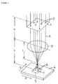
- Figure 1 uses an preferred embodiment of this invention to illustrate the basic principle which underlies this method to produce a mesh consisting of a thin material. Excimer laser beams L, which are emitted by an excimer laser oscillator, pass through
microscopic openings 2 inmask 1 and are thereby forced to assume a specified shape. The beams are then focused byobjective lens 3 and projected onto thin material (i.e., mesh material) 5, consisting of, for example, a polymer such as polysulfone, polyester, or polyamide, which is immobilized onwork stage 4, an XY table or the like. The reduced image of the pattern ofholes 2 inmask 1 is caused to appear onthin material 5. When the mesh process is carried out onmaterial 5 to produceholes 6, whose arrangement is identical to that ofpattern 2,mesh 7 is obtained. If f is the focal length ofobject lens 3, u is the distance fromobject lens 3 tomask 1, and v is the distance fromobject lens 3 tothin material 5 onwork stage 4, then according to a well-known formula, the relationship of u, f and v must satisfy
mask 1 to be produced onmaterial 5. If M is the magnification (= 1/magnification) of the image ofpattern 2 which is produced onmaterial 5, then M can be expressed in terms of the aforesaid u, v and f as
mask 1 and objectlens 3 are determined by the focal length f ofobject lens 3. Thus it is possible to createholes 6, which are identical to those ofpattern 2 inmask 1, at any desired magnification M. - A
mask 1 with numerous holes comprising apattern 2, as shown in Figure 1, will createnumerous holes 6 at a single time. However, it would also be possible to use amask 1 with asingle hole 2 and movethin material 5 by means ofwork stage 4. In this waysingle holes 6 could be created one by one to produce amesh 7 containing numerous holes. - Figures 2 (a) and (b) are partial elevation views illustrating another method for producing a thin mesh which is an preferred embodiment of this invention. In this embodiment, as shown in Figure 2 (a),
metal foil 8 is affixed to the top ofwork stage 4.Master mask 10 has asingle opening 9, which is created by etching or some similar process.Mask 10 shapes excimer laser beamL. Work stage 4 movesmetal foil 8 while a pattern ofholes 2 arranged in identical fashion toholes 6 in theprevious mask 1 is created inmetal foil 8 using excimer laser beam L. This produces amask 1 consisting of ametal foil 8 with a pattern ofholes 2, each of which is a reduced version of theaforesaid opening 9. Next, themask 1 produced in this way is set on a mask stage, as shown in Figure 2 (b), and a piece ofthin material 5, which may be polyamide or some similar substance, is affixed to workstage 4. A number of excimer laser beams L, which have passed through and been shaped bymask 1, at once create the same number ofholes 6 inmaterial 5, producing the desiredmesh 7. This method, then, allows us to manufacture athin mesh 7 containingnumerous holes 6 starting withmaster mask 1, which has only one relatively rough opening. - Figure 3 illustrates the configuration of
device 11, which produces a mesh according to this invention. In this figure, 12 is an excimer laser oscillator; 13 is a mask stage which supportsmask 1 and adjusts its position; 14 is a projection optics system; 15 is a totally reflective mirror; and 16 is an objective which creates an image ofpattern 2 on the surface ofmaterial 5. 17 is a work stage such as an X-Y or R-Θ stage to movematerial 5, which is loaded upon it, in two dimensions with respect to excimer laser beams L; 18 is a drive circuit which uses numerical values to control the speed, position, and so forth ofwork stage 17.Work stage 17 has an encoder or other device (not pictured) to detect the position of thework 19 is a device (a computer) to control the driving of the work stage. It has astorage device 20, which may be a floppy or hard disk drive to store the desired appearance of theholes 6 one wishes to create. The computer compares the signal representing the detected position of the work which is output by the device for that purpose with the desired appearance stored indevice 20 and evaluates how well they match. Based on this evaluation, it outputs to drive circuit 18 a signal representing the target position forwork stage 17. It also outputs to laser oscillator 12 a signal to adjust the intensity of the laser beam and a signal to begin oscillation. 21 is a display. - The excimer laser beam L emitted by
laser oscillator 12 is shaped into the desired beam pattern bymask 1 and passes throughprojection optics system 14. The beams are reflected by totallyreflective mirror 15 and pass through objective 16 to strikematerial 5 onwork stage 17. Before any of this takes place,mask stage 13 has adjusted the position ofmask 1, and the focal length ofoptical system 14 has been adjusted. The size ofholes 2 inmask 1 is adjusted by imaging them on the surface ofmaterial 5 at different magnifications M. Based on the desired appearance ofholes 6 which is stored indevice 20,control device 19 causes drivecircuit 18 to movework stage 17 over a path which is previously programmed. At the same time, it synchronously controls the oscillation oflaser oscillator 12 to produce the desired holes inmaterial 5. - This type of
device 11 can produce, for example, amesh 7 like that shown in Figure 4. In this method, just as in Figure 2 (a), amask 1 fashioned with the help of amaster mask 10 is placed inmask stage 13, andmaterial 5 is placed onwork stage 17. When excimer laser beam L passes throughmask 1, it is shaped into beams whose diameter is smaller than that ofholes 6.Control device 19 causes workstage 17 to be moved continuously in a circular pattern according to the shape forholes 6 which is stored indevice 20, and a number ofholes 6 arranged in a desired pattern are produced at one time by excimer laser beams L, which are smaller in diameter than the holes they are creating. When this method is used,mask 1 need not be changed each time the shape ofholes 6 needs to be modified. A pattern ofholes 6 of any desired shape can be created simply by recording indevice 20 the shape the holes are to be given and the path over which workstage 17 is to be moved. - This method is not limited to the creation of round holes in a regular formation, as shown in Figure 26. It can also produce an irregular arrangement of
holes 6 like that shown in Figure 5. To achieve this, one could either create amask 1 with an irregular array of holes, or createholes 6 one at a time in an irregular pattern. Using amask 1 with anirregular pattern 2 would allow us to produce amesh 7 with holes of different sizes, as shown in Figure 5. Oddly shapedholes 6 such as those pictured in Figure 6 could also be created, either by producing amask 1 with apattern 2 of holes shaped likeholes 6 in Figure 6, or by scanning an excimer laser beam L along the edge of eachhole 6 in Figure 6. - Figures 7 (a), (b) and (c) are cross sections of holes which illustrate other examples of methods for producing
holes 6 using thedevice 11 pictured in Figure 3. Figure 7 (a) is a cross section ofpreferred hole 22, the desired outcome.Hole 22 is rotationally symmetric with respect to axis P. Its edge is a smoothly curved surface. This type ofsymmetric hole 22 can be created by projecting an excimer laser beam L ontomaterial 5 while movingwork stage 17 along a path comprising a series of concentric circles. If the machining depth is changed at every radius r, ahole 6 of any desired cross section can be produced. Figure 7 (c) illustrates this machining process. Excimer laser beam L is moved while it is tracing concentric circles within a singlestationary hole 6 to create a circular hole inmaterial 5. By varying the depth to which the material is machined at different radii with respect to axis P, we can obtain a cross section with whatever number of steps we desire. The depth of machining is determined by N, the number of revolutions ofwork stage 17 while excimer laser beam L is emitted. (If v is the linear velocity in the circumferential direction, the period during which laser beam L is emitted is proportional to N/v. If the work is moved by means of an X-Y stage likestage 17, the linear velocity v in the circumferential direction is fixed irrespective of radius of machining r, so the number of revolutions N corresponds to the period during which laser beam L is emitted.) If instead of the cross section ofhole 22 shown in Figure 7 (a) we wish to produce a hole with a stepping-type cross section as in Figure 7 (b), the conditions for machining each step are determined by r, the radius with respect to axis P, and N, the number of revolutions ofstage 17. We can program the location where the beam will be projected on the topmost step as r5 and the number of revolutions on that step as N5, the location of the second step from the top as r4 and its number of revolutions as N4, the location of the third step from the top as r3 and its number of revolutions as N3 and so on. (r5, r4 and so on are made to differ by varying the diameter of laser beam L.) In thisway control device 19 can at once create a number ofholes 6 of the appearance shown in Figure 7 (b). By increasing the number of steps in Figure 7 (b) and gradually varying radius r, we can make the difference between the steps in the contour ofhole 6 very small and produce a hole with an adequately smooth interior surface, so this method could also be used to create thehole 22 pictured in Figure 7 (a). The number of times laser beam L is emitted will depend on the intensity of the beam. It may be set according to the total dose. When laser beam L is used to perform an ablation process (i.e., a process which relies on an analysis of photoexcitation), the speed of machining (i.e., how deeply the material will be machined with each pulse) can be varied to a certain degree by varying the energy density of the beam. Whenmesh 7 is turned upside down from the orientation pictured in Figure 7 (b) so that the narrow ends ofholes 6 face outward, it can be used in the type ofinhaler 101 pictured in Figure 26. - Figure 8 shows another method to produce a mesh which is an preferred embodiment of this invention. When excimer laser beam L is scanned over a circular path relative to
material 5, the beams L overlap differently on the inner and outer scanning paths. As a result, the effective energy intensity of beam L on the inner paths is greater than that on the outer paths. Since the way the beams overlap varies with the machining radius r, the average effective energy intensity of beam L will vary with machining radius r from the innermost to the outermost path even though the intensity of the beam L projected bylaser oscillator 12 does not vary. For this embodiment, if k is the fractional coefficient of beam intensity which is determined by machining radius r (average effective energy intensity/maximal energy intensity of emitted beam), the relationship of machining radius r, number of revolutions N and machining depth d can be expressed as
work stage 17 are programmed such that at beam location r1 in the center of the hole, number ofrevolutions 


way control device 19 can at once create a number ofholes 6 of the appearance shown in Figure 8. By using beam intensity coefficient k as described, we can accurately control machining depth d to produceholes 6 with precision contours. - Figure 9 shows the configuration of
device 31, another preferred embodiment of a device to produce a mesh according to this invention. Indevice mask device 11 pictured in Figure 3.Mask 32, which is placed in theaforesaid mask stage 13, has a number ofholes mask 32 shown in Figure 10 (a), for example, hasholes holes holes material 33 repeatedly at a fixed pitch, and 35 is a cutting device such as a laser cutter to cutmaterial 33 into fixed lengths or shapes onceholes 6 have been formed in it. 18 is a drive circuit to control the rate or the timing at whichmaterial 33 is fed. 19 is a control circuit to coordinatedrive circuit 18 andlaser oscillator 12 so that laser beam L is emitted synchronously with the timing at whichmaterial 33 is fed. - Excimer laser beam L, which is emitted by
laser oscillator 12, passes throughholes mask 32, which is fixed inmask stage 13. Laser beam L assumes shapes which are informed by the shapes of the holes in the mask, and these shaped beams strikeoptical system 14. Shaped beams L travel throughoptical system 14, are reflected bymirror 15, and pass through objective 16, which reduces them to a given magnification M. A reduced image of the mask pattern is projected onto the rolled piece ofmaterial 33 which is seated onfeeder device 34, andmaterial 33 is machined. Let us assume that we are using amask 32 with three holes, 2a, 2b and 2c, of different sizes, as shown in the rough sketch in Figure 11. If p is the pitch between every two images onmaterial 33, thendevice 31 would repeatedly execute the process of machining at least a third of the depth ofmaterial 33 with a single laser beam and the process of feedingmaterial 33 in increments of pitch p by means offeeder device 34. To give an example, let us assume thatmaterial 33 is being fed in the direction indicated by arrows in Figures 11 and 12. Asingle hole 6 is produced as follows. First, the laser beam L corresponding to the largest hole in the mask, 2a, creates the largest hole segment in the material, 36a, machining the hole to one third of its eventual depth (Figure 12 (a)).Material 33 is then fed over a distance equal to p, and the laser beam corresponding to the intermediate hole in the mask, 2b, machines the interior of the largest segment, 36a, excavating the hole to approximately two thirds of its eventual depth to createintermediate segment 36b (Figure 12 (b)).Material 33 is again fed over a distance equal to p, and the laser beam L corresponding to the smallest hole in the mask, 2c, produces the smallest segment of the hole, 36c, by machining the bottom ofintermediate segment 36b all the way through the material (Figure 12 (c)). When this process is performed repeatedly,numerous holes 6 are created inmaterial 33 at a constant pitch p, as shown in Figure 12 (d). Once processed,material 33 is transported to cuttingdevice 35, where it is cut to a previously determined shape (e.g., the shape that will allow it to fit in an inhaler) or length, thus completing the manufacture ofmesh 7. Once cut, meshes 7 are loaded onto a stacker or some similar device. Alternatively, uncut lengths ofmaterial 33 can be wound onto a drum or other receptacle by a winch. In the example we have been discussing, the material is machined starting with the largest hole segment, 36a. It would also be possible to feedmaterial 33 in the opposite direction and machine the hole starting with the smallest segment, 36c. - Figure 13 shows the configuration of
device 41, another preferred embodiment of a device to produce a thin mesh according to this invention. In this figure, 12 is an excimer laser oscillator; 15 is a totally reflective mirror; 1 is a mask containing a number ofholes 2; 42 is a projection optics system; and 43 is a work stage such as a Z-stage. The excimer laser beam L emitted bylaser oscillator 12 passes throughholes 2 inmask 1, which shape it into beams having the same form as those holes. The path of these laser beams is changed by totallyreflective mirror 15, and they are made to strikeprojection optics system 42. The projected image of the mask pattern, reduced as desired byoptical system 42, is projected onmaterial 5, which is seated onwork stage 43, and the material is machined to produceholes 6. - The aforesaid
projection optics system 42 can vertically project the image ofpattern 2 onto the surface ofmaterial 5, and is capable of changing the magnification of the image. A telecentric optical system could be used for this purpose. Figure 14 shows how aprojection optics system 42 like the one we have been discussing might be designed.Convex lens 44 is placed in the optical path of laser beam L directly behindmask 1.Imaging lens 45 is placed on the optical axis of the beam betweenlens 44 andwork stage 43. This constitutes what is known as a telecentric optical system. One characteristic of this optical system is that when it is defocused the center of the image and the periphery both undergo the same degree of distortion. For this reason the entire work surface can be defocused homogeneously. In thedevice 41 pictured in Figure 13,mirror 15 is placed abovemask 1. However, it would be equally acceptable to placelens 44 ofoptical system 42 andmask 1 on a horizontal optical path andposition mirror 15 betweenlenses - The excimer laser beam L pictured in Figure 13 is projected vertically toward
work stage 43.Stage 43 can go up and down, which means that it moves parallel to the optical path of laser beam L. The stage is controlled bydevice 19 and drivecircuit 18.Control device 19 containsdevice 20, which stores the drive path for the work stage. It raises and lowersstage 43 according to a previously recorded program to control the degree to which the projected image is defocused, and it synchronously controls the oscillation oflaser oscillator 12. - With this type of
device 41, then, the diameter ofhole 6 is set to d on the imaging plane (where the degree of defocus is 0). Whenwork stage 43 is driven the position ofmaterial 5 , as shown in Figure 15(a), is changed. When the processing is done on a plane which is a distance of ± z1 from the focal plane, the image will be enlarged and the dimensions of the holes will be increased. At a distance of ± z2 (where z2 > z1), the image will be even larger and the dimensions even further increased. By carefully investigating this correspondence in a quantitative fashion, we can discover what dimensions will be produced at each degree of defocus, and we can obtain the relationship between the position of the work (or the degree of defocus and the dimensions of the pattern (or the degree of distortion). An example of such a relationship is given in Figure 15 (b). - With a
device 41 configured as described above, we can controlwork stage 43 so that the degree to which the image is defocused varies over time, as shown in Figure 16 (a). This would produce a smoothly taperedhole 6 as shown in Figure 16 (b). Ifstage 43 is controlled so that the degree of defocus varies as shown in Figure 17 (a), the resultinghole 6 will be shaped like a top, as shown in Figure 17 (b). And ifstage 43 is controlled so that the degree of defocus varies as shown in Figure 18 (a), the barrel-shapedhole 6 shown in Figure 18 (b) will be produced. - Figure 19 illustrates the configuration of
device 51, yet another preferred embodiment of a device to produce a thin mesh according to this invention. In this figure, 12 is an excimer laser oscillator; 52 is a drive device which supportsmask 53, adjusts its position, and drives it; 14 is a projection optics system; 15 is a totally reflective mirror; 16 is an objective to produce the image ofpattern 58 on the surface ofthin material 5; 17 is a work stage to movematerial 5, which is seated upon it, relative to excimer laser beam L; 18 is a drive circuit to control the position ofstage 17 and, throughdrive device 52, the amount of drive applied to mask 53; and 19 is a device to control the drive.Control device 19 containsdevice 20, which controlsstage 17 and drivedevice 52 according to a previously programmed pattern and, at the same time, synchronously controls the oscillation oflaser oscillator 12. - Figure 20 shows plan views of the
aforesaid mask 53.Mask 53 consists of two submasks, 54 and 55, which are put together one on top of the other. Both of the submasks havenumerous holes submask 54 and holes 57 insubmask 55 are made to overlap. Ifsubmasks holes 58 will be 100% open. Ifsubmasks holes holes holes 58 can be adjusted as desired. In Figures 20 and 21, holes 56 and 57 are square or diamond-shaped; however, this shape is not an essential requirement. Holes which are triangular, hexagonal, or of any other shape may also be used. With the square or diamond-shaped holes shown in the drawings, holes 58 remain the same shape when their dimensions change. - Figure 22 shows a front elevation view of
drive device 52, the device which drives theaforesaid mask 53 to change the aperture ofholes 58. Submasks 54 and 55 are retained byholders Holders mechanism 61, consisting of linear bearings or the like, in such a way that they can move smoothly parallel to each other.Holders Screws 64 are connected topulse stepping motors 66 throughcouplings 65. Indrive device 52, steppingmotors 66 are controlled to the same phase, so thatsubmasks holes submasks holes 58 do not move. Thus the optical axis of each excimer laser beam L which passes through ahole 58 remains fixed. - With a
device 51 like that described above, we can machine meshholes 6 whose diameter varies with their depth, as shown in Figure 23. First, the aperture ofholes 58 is set at 100% so that a large area ofmaterial 5 is machined to an appropriate depth, as shown in Figure 23 (a). The aperture of the holes inmask 53 is then constricted slightly by drivingdevice 52, and a slightly smaller area ofmaterial 5 is machined to an appropriate depth, as shown in Figure 23 (b). The aperture is again constricted in the same way, and an even smaller area is removed, as shown in Figure 23 (c). Finally, the aperture is further constricted, and a hole of even smaller diameter is bored completely throughmaterial 5, as shown in Figure 23 (d). In this way numerous throughholes 6 can be formed. - The order of the machining processes used to create
hole 6 in Figure 23 could also be reversed. In this case, the size of the segments to be removed by machining would be systematically increased. The diameter ofhole 6 would be increased methodically as shown in Figures 24 (a), (b), (c) and (d) (Note: Figures (b) and (c) have been exchanged in the drawing.) to produce ahole 6 of the intended shape. If the first narrow segment which is machined are made to taper automatically, the result would be a smooth, gradual change of diameter, as can be surmised from Figure 24. In Figures 23 and 24, the size ofhole 53 is increased in four steps; however, the size of theholes comprising pattern 58 inmask 53 might, for example, be increased with every shot of excimer laser beam L. In this case, the machining could be controlled more precisely, and the resultingholes 6 would have smooth sides. It is not essential thatmask 53 be driven discontinuously over time. Driving it continuously will create ahole 6 with a smooth cross section. It would also be possible to adjustmask 53 manually without usingdrive device 52. - Figure 25 is a front elevation view of
drive device 71, another device which can be used to drive the mask indevice 51.Drive device 71 has two holders, 72 and 73, one of which is atop the other on the same side of the mask. To each of these holders is affixed one side of one ofsubmasks Holders mechanism 74, consisting of linear bearings or the like, in such a way that they can move horizontally. On the lower surface ofupper holder 72 and the upper surface oflower holder 73 areracks Drive gear 77, which is driven to rotate by a motor (not pictured), engages simultaneously with both racks. Whengear 77 is rotated,submasks holes 56 insubmask 54 withholes 57 insubmask 55, grow bigger or smaller. - When the mesh produced according to this invention is made from a material which is safe for human beings, such as polysulfone or polyester, it can be used in medical equipment like the inhaler pictured in Figure 26. With an inhaler, the distance which the drug must be transported to reach the affected area differs, so the effectiveness varies with the diameter of the spray particles. This diameter is highly dependent on the shape of the holes in the mesh. This invention allows us to achieve holes with an preferred cross section for spraying. Furthermore, the shape of the holes in the mesh can be changed as needed for different affected areas while the frequency of the oscillator remains constant. If we change the mesh, then, we can use the same inhaler to deliver a drug to a number of affected areas. A mesh produced from a material such as polyamide can be used in equipment for a physics or chemistry lab.
- In the embodiments discussed above, an excimer laser oscillator is used as the light source. It would also be possible to use the fourth high frequency of a YAG laser, a parametric oscillator, or an ultraviolet (UV) beam.
- The device described above is not limited to the machining of thin materials composed of polymers. It could also be used to produce a mesh from a foil of some metal other than nickel, such as titanium or stainless steel, which are not harmful to humans. The resulting product could also be used as a thin mesh. A mesh could also be produced from a ceramic material, and the resulting product could be used as a thin mesh.
- This invention allows us to choose the material to be used to produce a thin mesh. Having a choice of materials allows us to achieve a flexible mesh of a material with superior resistance to corrosion and chemicals, such as a polymer or ceramic. The preferred material can be selected for the intended application of the mesh. A thin mesh produced from a material such as polysulfone or polyester, which are safe for humans and highly resistant to corrosion, is preferred for use in medical devices such as inhalers or in food production equipment. A mesh made of polyamide would be suitable for use in equipment designed for physics and chemistry labs. Many other applications will doubtless be found for such meshes.
- With this invention, microscopic through holes are created by an ultraviolet beam. This allows a microscopic machining process to be performed on the material of one's choice. Through holes can be machined to any desired shape and cross-sectional contour, using either step-by-step or smooth tapering.
- A method to produce through holes which entails moving an ultraviolet beam and a piece of thin material relative to each other allows us to produce holes of the desired shape irrespective of the shape of the mask. This eliminates the time required to change the mask in prior art methods. If a number of ultraviolet beams are used, a number of through holes can be created at the same time, resulting in a shorter processing time. This also facilitates automation of the mesh production process.
- Another method employs a mask with a pattern containing a number of holes of different shapes and diameters. The shape of the through holes is changed at different depths of machining. This method allows us to create in the thin material microscopic mesh holes consisting of many steps whose machining can be precisely controlled, and it can produce through holes with whatever cross section we might desire. In particular, if the pattern in the mask consists of numerous holes of different shapes or diameters but at a fixed pitch, we can create a number of holes at the same time. This reduces the processing time and improves efficiency. If a rolled or other long piece of material is cut into pieces after the mesh is created, efficiency is further enhanced.
- A method by which the focal plane of an ultraviolet beam and a piece of thin material move relative to each other parallel to the optical axis of the beam allows us to vary the distance between the focal plane and the material continuously over time. In this way we can vary the diameter of the hole continuously and smoothly by varying the depth of machining. We can easily produce through holes with a smoothly tapering inner surface.
- If we change the dimensions of the holes in the mask by driving the two halves of it, we can achieve holes of various sizes in the same mask and create through holes of various dimensions without changing the mask or adjusting the optical system. By varying the dimensions of the mask holes while the through holes are being machined, we can cause the diameter of each hole to vary. This produces through holes whose diameter varies with their depth, either continuously or discontinuously, and whose cross sections have a desired shape.
Claims (15)
- A thin mesh which is distinguished by the fact that it contains numerous microscopic through holes with a high aspect ratio which are formed by irradiating a thin material with ultraviolet beams.
- The thin mesh described in Claim 1 of this application, which is further distinguished by the fact that the aforesaid thin material is a polymer.
- The thin mesh described in Claim 1 of this application, which is further distinguished by the fact that the aforesaid thin material is a ceramic.
- The thin mesh described in Claim 1 of this application, which is further distinguished by the fact that the aforesaid thin material is a metal film.
- A method for producing a thin mesh which is distinguished by the fact that it consists of creating numerous microscopic through holes in a thin material by irradiating it with ultraviolet beams.
- A method for producing a thin mesh which is distinguished by the fact that it consists of simultaneously irradiating a material with a number of ultraviolet beams of sufficiently small diameters to produce through holes of the desired shape, and by moving the thin material which is being processed and the aforesaid ultraviolet beams relative to each other, simultaneously creating a number of through holes of the desired cross-sectional appearance.
- A device to produce a thin mesh which is distinguished by the fact that it is equipped with: a device to emit ultraviolet beams of sufficiently small diameters to produce through holes of the desired shape; and a device to move the thin material which is being processed and the aforesaid ultraviolet beams relative to each other.
- A device to produce a thin mesh which is distinguished by the fact that it is equipped with: a device to emit ultraviolet beams of sufficiently small diameters to produce through holes of the desired shape; a device to store the shape into which the aforesaid through holes are to be formed; a device to move the thin material which is being processed and the aforesaid ultraviolet beams relative to each other; a device on the aforesaid translator to detect the locations to be processed; a device to compare the signal from the aforesaid device to detect the locations to be processed with the shapes to be formed which are stored in the aforesaid storage device; and a device which, based on the comparison made by the above comparing device, controls the aforesaid translator according to the shape to be formed and outputs to the aforesaid emitting device a signal causing it to oscillate the ultraviolet beams and a signal to control the intensity of those beams.
- A method to produce a thin mesh which is distinguished by the fact that a mask is used, which provides a pattern of holes of different shapes or diameters. Different holes are aligned sequentially over the same region of the thin material and each is irradiated with an ultraviolet beam in order to create in the thin material through holes with the desired cross-sectional shape.
- A device to produce a thin mesh which is distinguished by the fact that it is equipped with: a mask, which has a pattern of holes which are at the same pitch but which differ from each other in shape or diameter; a device to emit and focus simultaneously on the thin material the ultraviolet beams which pass through the pattern of holes in the aforesaid mask; and a device to move the thin material at increments equal to the pitch.
- The device to produce a thin mesh which is described in Claim 10 of this application, which is further distinguished by the fact that it is equipped with a device to cut the aforesaid thin material in which holes have been formed.
- A method to produce a thin mesh which is distinguished by the fact that it entails using an ultraviolet beam to project onto the thin material the image of the pattern of holes in the mask and then varying the position of the thin material with respect to the plane on which the aforesaid image is focused, along a path which is parallel to the optical axis of the ultraviolet beam. In this way holes can be created in the thin material whose diameter varies with their depth.
- A device to produce a thin mesh which is distinguished by the fact that it is equipped with: a device to generate an ultraviolet beam; a mask with a pattern of holes in it; an optical system which can project onto the thin material which is to be processed the image of the aforesaid pattern of holes and which is capable of varying its magnification; and a device to move the aforesaid thin material on a path which is parallel to the optical axis of the ultraviolet beam.
- A method to produce a thin mesh which is distinguished by the fact that it entails overlaying at least two submasks containing openings, matching up the aforesaid openings to create a pattern of holes, and varying slightly the overlap of the aforesaid holes so as to vary the dimensions of the holes in the aforesaid pattern. When an ultraviolet beam is passed through the aforesaid pattern of holes, through holes are created in the thin material.
- A device to produce a thin mesh which is distinguished by the fact that it is equipped with: a device to generate an ultraviolet beam; a mask consisting of at least two overlaid submasks containing openings whose dimensions can be varied by varying slightly the way in which the aforesaid submasks overlap; a device to vary the amount of overlap of the aforesaid submasks; and an optical system to project onto the thin material which is to be processed an ultraviolet beam which has passed through the aforesaid pattern of holes.
Applications Claiming Priority (7)
| Application Number | Priority Date | Filing Date | Title |
|---|---|---|---|
| JP120932/93 | 1993-04-22 | ||
| JP12093293 | 1993-04-22 | ||
| JP12093293 | 1993-04-22 | ||
| JP309726/93 | 1993-11-15 | ||
| JP30972693 | 1993-11-15 | ||
| JP30972693A JP3211525B2 (en) | 1993-04-22 | 1993-11-15 | Thin material mesh, its manufacturing method and its manufacturing apparatus |
| PCT/IB1994/000078 WO1994025259A1 (en) | 1993-04-22 | 1994-04-22 | Thin mesh, manufacturing method thereof and manufacturing device therefor |
Publications (3)
| Publication Number | Publication Date |
|---|---|
| EP0729827A4 EP0729827A4 (en) | 1996-04-09 |
| EP0729827A1 true EP0729827A1 (en) | 1996-09-04 |
| EP0729827B1 EP0729827B1 (en) | 2000-07-05 |
Family
ID=26458419
Family Applications (1)
| Application Number | Title | Priority Date | Filing Date |
|---|---|---|---|
| EP94913775A Expired - Lifetime EP0729827B1 (en) | 1993-04-22 | 1994-04-22 | Device and method for producing a thin mesh on a thin material |
Country Status (6)
| Country | Link |
|---|---|
| US (1) | US6008468A (en) |
| EP (1) | EP0729827B1 (en) |
| JP (1) | JP3211525B2 (en) |
| CA (1) | CA2161223C (en) |
| DE (1) | DE69425155T2 (en) |
| WO (1) | WO1994025259A1 (en) |
Cited By (5)
| Publication number | Priority date | Publication date | Assignee | Title |
|---|---|---|---|---|
| EP0976487A1 (en) * | 1998-07-30 | 2000-02-02 | Societe Nationale D'etude Et De Construction De Moteurs D'aviation "Snecma" | Process for excimer laser machining of holes or forms with variable shapes |
| US6123068A (en) * | 1993-05-21 | 2000-09-26 | Aradigm Corporation | Systems for the intrapulmonary delivery of aerosolized aqueous formulations |
| EP1295647A1 (en) * | 2001-09-24 | 2003-03-26 | The Technology Partnership Public Limited Company | Nozzles in perforate membranes and their manufacture |
| US7380550B2 (en) | 2004-01-30 | 2008-06-03 | Hewlett-Packard Development Company, L.P. | Systems and methods for particle detection |
| CN101823180A (en) * | 2009-03-06 | 2010-09-08 | 索尼公司 | Light processing method and mask |
Families Citing this family (51)
| Publication number | Priority date | Publication date | Assignee | Title |
|---|---|---|---|---|
| KR19990007929A (en) | 1995-04-26 | 1999-01-25 | 데이빗로스클리블랜드 | Multi-faced repeated exposure method and apparatus |
| US6215269B1 (en) * | 1996-05-21 | 2001-04-10 | Kent Gregg | Method of exposing a path on a curved, or otherwise irregularly shaped, surface |
| JP3689490B2 (en) * | 1996-06-07 | 2005-08-31 | キヤノン株式会社 | Nozzle member manufacturing method and processing apparatus using the same |
| DE19739720C1 (en) * | 1997-09-10 | 1998-10-22 | Roman Eissfeller Gmbh | Automatic welding unit for high precision welding |
| US6354516B1 (en) * | 1999-11-02 | 2002-03-12 | Aradigm Corporation | Pore structures for reduced pressure aerosolization |
| US6313435B1 (en) * | 1998-11-20 | 2001-11-06 | 3M Innovative Properties Company | Mask orbiting for laser ablated feature formation |
| DE19915000C2 (en) * | 1999-04-01 | 2002-05-08 | Microlas Lasersystem Gmbh | Device and method for controlling the intensity distribution of a laser beam |
| DE60038400T2 (en) * | 1999-04-02 | 2009-04-23 | Murata Mfg. Co., Ltd., Nagaokakyo-shi | Laser process for machining holes only in a ceramic green sheet with a carrier film |
| US6888096B1 (en) | 1999-09-28 | 2005-05-03 | Sumitomo Heavy Industries, Ltd. | Laser drilling method and laser drilling device |
| FI108682B (en) | 2000-06-30 | 2002-02-28 | Nokia Corp | Method for manufacturing the keyboard of an electronic device |
| US7147338B2 (en) | 2001-04-09 | 2006-12-12 | Kent Gregg | Circuit on a curved, or otherwise irregularly shaped, surface, such as on a helmet to be worn on the head, including a fiber optic conductive path |
| US6623103B2 (en) | 2001-04-10 | 2003-09-23 | Lexmark International, Inc. | Laser ablation method for uniform nozzle structure |
| US7118227B2 (en) | 2001-04-25 | 2006-10-10 | Matsushita Electric Industrial Co., Ltd. | Projection display device |
| US6881203B2 (en) | 2001-09-05 | 2005-04-19 | 3M Innovative Properties Company | Microneedle arrays and methods of manufacturing the same |
| US6627844B2 (en) | 2001-11-30 | 2003-09-30 | Matsushita Electric Industrial Co., Ltd. | Method of laser milling |
| US6908453B2 (en) | 2002-01-15 | 2005-06-21 | 3M Innovative Properties Company | Microneedle devices and methods of manufacture |
| MXPA05000597A (en) | 2002-07-19 | 2005-04-28 | 3M Innovative Properties Co | Microneedle devices and microneedle delivery apparatus. |
| US8012136B2 (en) | 2003-05-20 | 2011-09-06 | Optimyst Systems, Inc. | Ophthalmic fluid delivery device and method of operation |
| WO2004103478A1 (en) | 2003-05-20 | 2004-12-02 | Collins James F | Ophthalmic drug delivery system |
| US7021560B2 (en) | 2003-09-25 | 2006-04-04 | Deka Products Limited Partnership | System and method for aerosol delivery |
| US7342660B2 (en) * | 2003-09-25 | 2008-03-11 | Deka Products Limited Partnership | Detection system and method for aerosol delivery |
| US7728256B2 (en) * | 2003-12-24 | 2010-06-01 | Lg Display Co., Ltd. | Silicon crystallization apparatus and silicon crystallization method thereof |
| MX2008001323A (en) * | 2005-07-27 | 2008-09-19 | Power Med Interventions Inc | System and method for forming staple pockets of a surgical stapler. |
| JP2007130816A (en) * | 2005-11-08 | 2007-05-31 | Ricoh Co Ltd | Liquid drop discharge head, its manufacturing process and ink jet recorder |
| WO2007092637A2 (en) | 2006-02-09 | 2007-08-16 | Deka Products Limited Partnership | Patch-sized fluid delivery systems and methods |
| JP2008016687A (en) * | 2006-07-07 | 2008-01-24 | Nippon Chemicon Corp | Manufacturing method of electrolytic capacitor |
| FR2909297B1 (en) * | 2006-11-30 | 2010-03-05 | Snecma | METHOD FOR LASER DRILLING OF A PIECE OF COMPOSITE MATERIAL WITH CERAMIC MATRIX, HOLE OBTAINED BY THIS PROCESS, PIECE OF COMPOSITE MATERIAL WITH CERAMIC MATRIX COMPRISING IT, TURBOREACTOR COMPRISING SUCH A PIECE |
| JP2008221334A (en) * | 2007-02-17 | 2008-09-25 | Sii Printek Inc | Laser beam machine, laser beam machining method, nozzle plate, ink-jet head and ink-jet recorder |
| JP5092446B2 (en) * | 2007-02-26 | 2012-12-05 | パナソニック株式会社 | Mask for laser processing |
| JP5157195B2 (en) * | 2007-02-28 | 2013-03-06 | パナソニック株式会社 | Laser processing method and microlens array type manufacturing method using the same |
| JP5073468B2 (en) * | 2007-12-13 | 2012-11-14 | 三菱電機株式会社 | Method for manufacturing photovoltaic device |
| KR100902150B1 (en) * | 2008-09-23 | 2009-06-10 | (주)큐엠씨 | Apparatus and method for manufacturing led |
| US20100129617A1 (en) * | 2008-11-21 | 2010-05-27 | Corrigan Thomas R | Laser ablation tooling via sparse patterned masks |
| EA201390121A8 (en) | 2010-07-15 | 2014-02-28 | Коринтиан Офтэлмик, Инк. | METHOD AND SYSTEM FOR PERFORMING REMOTE TREATMENT AND CONTROL |
| JP5964826B2 (en) | 2010-07-15 | 2016-08-03 | アイノビア,インコーポレイティド | Drop generation device |
| US10154923B2 (en) | 2010-07-15 | 2018-12-18 | Eyenovia, Inc. | Drop generating device |
| CA2805425C (en) | 2010-07-15 | 2019-07-23 | Corinthian Ophthalmic, Inc. | Ophthalmic drug delivery |
| US9125992B2 (en) * | 2011-09-16 | 2015-09-08 | Melvin A. Finke | Fluid delivery device with filtration |
| WO2013090468A1 (en) | 2011-12-12 | 2013-06-20 | Corinthian Ophthalmic, Inc. | High modulus polymeric ejector mechanism, ejector device, and methods of use |
| JP5777798B2 (en) * | 2012-03-12 | 2015-09-09 | 三菱電機株式会社 | Method for manufacturing solar battery cell |
| JP2013202409A (en) * | 2012-10-25 | 2013-10-07 | Tanaka Kikinzoku Kogyo Kk | Method for manufacturing mesh for nebulizer |
| JP5157000B1 (en) * | 2012-03-28 | 2013-03-06 | 田中貴金属工業株式会社 | Nebulizer mesh |
| EP2644282B1 (en) | 2012-03-28 | 2015-10-21 | Tanaka Kikinzoku Kogyo K.K. | Mesh for nebulizer and production method thereof |
| JP2014004209A (en) * | 2012-06-26 | 2014-01-16 | Omron Healthcare Co Ltd | Liquid spray apparatus |
| JP2014004210A (en) * | 2012-06-26 | 2014-01-16 | Omron Healthcare Co Ltd | Liquid spray apparatus |
| EP2778784B8 (en) * | 2013-03-11 | 2022-02-23 | Esko-Graphics Imaging GmbH | Apparatus and method for multi-beam direct engraving of elastomeric printing plates and sleeves |
| KR102134363B1 (en) * | 2013-09-10 | 2020-07-16 | 삼성디스플레이 주식회사 | Method for manufacturing metal mask and metal mask using the same |
| US10137616B2 (en) * | 2013-09-30 | 2018-11-27 | Disney Enterprises, Inc. | Fabricating lightweight skin systems for large scale robotic characters |
| US10384306B1 (en) * | 2015-06-10 | 2019-08-20 | Seagate Technology Llc | Laser cutting array with multiple laser source arrangement |
| KR20240034855A (en) | 2017-06-10 | 2024-03-14 | 아이노비아 인코포레이티드 | Methods and devices for handling a fluid and delivering the fluid to the eye |
| US20190151996A1 (en) * | 2017-11-22 | 2019-05-23 | Roche Diabetes Care, Inc. | Multiple laser processing for biosensor test strips |
Citations (4)
| Publication number | Priority date | Publication date | Assignee | Title |
|---|---|---|---|---|
| US4621912A (en) * | 1985-02-14 | 1986-11-11 | Meyer Donald R | Foraminated optical contact lens |
| EP0365195A2 (en) * | 1988-10-12 | 1990-04-25 | ROLLS-ROYCE plc | Laser machining method |
| EP0432992A1 (en) * | 1989-12-12 | 1991-06-19 | Bespak plc | Dispensing apparatus |
| DE4106423A1 (en) * | 1990-04-28 | 1991-10-31 | Mitsubishi Electric Corp | OPTICAL MACHINING DEVICE |
Family Cites Families (20)
| Publication number | Priority date | Publication date | Assignee | Title |
|---|---|---|---|---|
| US4622058A (en) * | 1984-06-22 | 1986-11-11 | International Business Machines Corporation | Formation of a multi-layer glass-metallized structure formed on and interconnected to multi-layered-metallized ceramic substrate |
| JPH07108468B2 (en) * | 1986-07-30 | 1995-11-22 | 株式会社ニコン | Laser processing equipment |
| JPH01266983A (en) * | 1988-04-20 | 1989-10-24 | Hitachi Seiko Ltd | Piercing machine for printed board |
| US4879451A (en) * | 1988-07-14 | 1989-11-07 | Sun-Flex Company, Inc. | Laser cut video display terminal filter screen |
| US4894115A (en) * | 1989-02-14 | 1990-01-16 | General Electric Company | Laser beam scanning method for forming via holes in polymer materials |
| JPH03180413A (en) * | 1989-12-08 | 1991-08-06 | Nkk Corp | Apparatus for controlling inclination angle of charged material in vertical type furnace |
| US5066357A (en) * | 1990-01-11 | 1991-11-19 | Hewlett-Packard Company | Method for making flexible circuit card with laser-contoured vias and machined capacitors |
| US5213876A (en) * | 1990-01-11 | 1993-05-25 | Hewlett-Packard Company | Flexible circuit card with laser-contoured VIAs and machined capacitors |
| JPH03226392A (en) * | 1990-01-31 | 1991-10-07 | Hitachi Ltd | Laser beam machining method |
| FR2659971B1 (en) * | 1990-03-20 | 1992-07-10 | Dassault Avions | PROCESS FOR PRODUCING THREE-DIMENSIONAL OBJECTS BY PHOTO-TRANSFORMATION AND APPARATUS FOR CARRYING OUT SUCH A PROCESS. |
| JP2706350B2 (en) * | 1990-04-27 | 1998-01-28 | キヤノン株式会社 | Laser drilling machine |
| JPH04100689A (en) * | 1990-08-14 | 1992-04-02 | Tsubakimoto Chain Co | Quintaxial table for laser beam machine |
| JPH04187392A (en) * | 1990-11-22 | 1992-07-06 | Canon Inc | Laser beam drilling machine |
| US5389954A (en) * | 1990-11-21 | 1995-02-14 | Canon Kabushiki Kaisha | Laser process apparatus for forming holes in a workpiece |
| JP2701183B2 (en) * | 1991-08-09 | 1998-01-21 | 株式会社小松製作所 | Liquid crystal mask laser marker |
| JPH05228669A (en) * | 1991-12-27 | 1993-09-07 | Polymer Processing Res Inst | Method and device for manufacturing perforated web with light beam |
| GB9202434D0 (en) * | 1992-02-05 | 1992-03-18 | Xaar Ltd | Method of and apparatus for forming nozzles |
| US5367143A (en) * | 1992-12-30 | 1994-11-22 | International Business Machines Corporation | Apparatus and method for multi-beam drilling |
| US5378137A (en) * | 1993-05-10 | 1995-01-03 | Hewlett-Packard Company | Mask design for forming tapered inkjet nozzles |
| US5539175A (en) * | 1994-03-21 | 1996-07-23 | Litel Instruments | Apparatus and process for optically ablated openings having designed profile |
-
1993
- 1993-11-15 JP JP30972693A patent/JP3211525B2/en not_active Expired - Fee Related
-
1994
- 1994-04-22 WO PCT/IB1994/000078 patent/WO1994025259A1/en active IP Right Grant
- 1994-04-22 CA CA002161223A patent/CA2161223C/en not_active Expired - Fee Related
- 1994-04-22 DE DE69425155T patent/DE69425155T2/en not_active Expired - Lifetime
- 1994-04-22 EP EP94913775A patent/EP0729827B1/en not_active Expired - Lifetime
-
1997
- 1997-10-17 US US08/953,419 patent/US6008468A/en not_active Expired - Lifetime
Patent Citations (4)
| Publication number | Priority date | Publication date | Assignee | Title |
|---|---|---|---|---|
| US4621912A (en) * | 1985-02-14 | 1986-11-11 | Meyer Donald R | Foraminated optical contact lens |
| EP0365195A2 (en) * | 1988-10-12 | 1990-04-25 | ROLLS-ROYCE plc | Laser machining method |
| EP0432992A1 (en) * | 1989-12-12 | 1991-06-19 | Bespak plc | Dispensing apparatus |
| DE4106423A1 (en) * | 1990-04-28 | 1991-10-31 | Mitsubishi Electric Corp | OPTICAL MACHINING DEVICE |
Non-Patent Citations (1)
| Title |
|---|
| See also references of WO9425259A1 * |
Cited By (6)
| Publication number | Priority date | Publication date | Assignee | Title |
|---|---|---|---|---|
| US6123068A (en) * | 1993-05-21 | 2000-09-26 | Aradigm Corporation | Systems for the intrapulmonary delivery of aerosolized aqueous formulations |
| EP0976487A1 (en) * | 1998-07-30 | 2000-02-02 | Societe Nationale D'etude Et De Construction De Moteurs D'aviation "Snecma" | Process for excimer laser machining of holes or forms with variable shapes |
| FR2781707A1 (en) * | 1998-07-30 | 2000-02-04 | Snecma | EXCIMERATED LASER MACHINING PROCESS OF HOLES OR SHAPES WITH VARIABLE PROFILE |
| EP1295647A1 (en) * | 2001-09-24 | 2003-03-26 | The Technology Partnership Public Limited Company | Nozzles in perforate membranes and their manufacture |
| US7380550B2 (en) | 2004-01-30 | 2008-06-03 | Hewlett-Packard Development Company, L.P. | Systems and methods for particle detection |
| CN101823180A (en) * | 2009-03-06 | 2010-09-08 | 索尼公司 | Light processing method and mask |
Also Published As
| Publication number | Publication date |
|---|---|
| DE69425155T2 (en) | 2001-03-22 |
| EP0729827A4 (en) | 1996-04-09 |
| US6008468A (en) | 1999-12-28 |
| EP0729827B1 (en) | 2000-07-05 |
| JPH071172A (en) | 1995-01-06 |
| DE69425155D1 (en) | 2000-08-10 |
| JP3211525B2 (en) | 2001-09-25 |
| CA2161223C (en) | 2000-05-16 |
| WO1994025259A1 (en) | 1994-11-10 |
| CA2161223A1 (en) | 1994-11-10 |
Similar Documents
| Publication | Publication Date | Title |
|---|---|---|
| EP0729827B1 (en) | Device and method for producing a thin mesh on a thin material | |
| EP0822881B1 (en) | Laser imaging ablation method | |
| JP2800937B2 (en) | Equipment for manufacturing parts by selective sintering | |
| JP2797684B2 (en) | Nozzle manufacturing method and manufacturing apparatus | |
| JPH03193311A (en) | Laser machining method for mold having microtexture surface | |
| US7994452B2 (en) | Laser beam machining apparatus | |
| US20040012124A1 (en) | Apparatus and method of fabricating small-scale devices | |
| JP5803316B2 (en) | Manufacturing method of structure | |
| EP0525902A1 (en) | Laser profiling of lens edge | |
| JPWO2018181344A1 (en) | Processing method and processing system | |
| JP2012240216A (en) | Three-dimensional modeling apparatus, modeled object, and method for manufacturing modeled object | |
| US20060037949A1 (en) | Laser modification of complex objects | |
| JP4455884B2 (en) | Laser ablation method using a constant laser scanning path algorithm. | |
| JP4527567B2 (en) | Laser processing apparatus and laser processing method | |
| US6501045B1 (en) | Method and apparatus for controlling the taper angle of the walls of laser machined features | |
| JP3800795B2 (en) | Laser processing condition automatic setting method and laser processing condition automatic setting device | |
| JP3518351B2 (en) | Method of forming composite shape on workpiece surface by energy beam and article obtained by this method | |
| JP2558355B2 (en) | Three-dimensional shape forming method | |
| KR102189459B1 (en) | Method for drilling hole and the drilling apparatus | |
| JPH05124115A (en) | Optical formation apparatus and formation method | |
| JP2628189B2 (en) | Drilling method by laser beam | |
| CN117182358B (en) | Fine metal mask laser processing device and processing method thereof | |
| JPH03193289A (en) | Laser beam machine | |
| WO2024080034A1 (en) | Laser machining apparatus, laser machining method, machining program creation method, and machining program configuration method | |
| JP2020537049A (en) | Equipment and methods for making 3D workpieces |
Legal Events
| Date | Code | Title | Description |
|---|---|---|---|
| A4 | Supplementary search report drawn up and despatched | ||
| AK | Designated contracting states |
Kind code of ref document: A4 Designated state(s): DE FR GB IT |
|
| PUAI | Public reference made under article 153(3) epc to a published international application that has entered the european phase |
Free format text: ORIGINAL CODE: 0009012 |
|
| 17P | Request for examination filed |
Effective date: 19951120 |
|
| AK | Designated contracting states |
Kind code of ref document: A1 Designated state(s): DE FR GB IT |
|
| 17Q | First examination report despatched |
Effective date: 19981013 |
|
| RTI1 | Title (correction) |
Free format text: DEVICE AND METHOD FOR PRODUCING A THIN MESH ON A THIN MATERIAL |
|
| RTI1 | Title (correction) |
Free format text: DEVICE AND METHOD FOR PRODUCING A THIN MESH ON A THIN MATERIAL |
|
| GRAG | Despatch of communication of intention to grant |
Free format text: ORIGINAL CODE: EPIDOS AGRA |
|
| GRAG | Despatch of communication of intention to grant |
Free format text: ORIGINAL CODE: EPIDOS AGRA |
|
| GRAH | Despatch of communication of intention to grant a patent |
Free format text: ORIGINAL CODE: EPIDOS IGRA |
|
| GRAH | Despatch of communication of intention to grant a patent |
Free format text: ORIGINAL CODE: EPIDOS IGRA |
|
| GRAA | (expected) grant |
Free format text: ORIGINAL CODE: 0009210 |
|
| AK | Designated contracting states |
Kind code of ref document: B1 Designated state(s): DE FR GB IT |
|
| PG25 | Lapsed in a contracting state [announced via postgrant information from national office to epo] |
Ref country code: FR Free format text: THE PATENT HAS BEEN ANNULLED BY A DECISION OF A NATIONAL AUTHORITY Effective date: 20000705 |
|
| REF | Corresponds to: |
Ref document number: 69425155 Country of ref document: DE Date of ref document: 20000810 |
|
| ET | Fr: translation filed | ||
| ITF | It: translation for a ep patent filed |
Owner name: ING. C. GREGORJ S.P.A. |
|
| PLBE | No opposition filed within time limit |
Free format text: ORIGINAL CODE: 0009261 |
|
| STAA | Information on the status of an ep patent application or granted ep patent |
Free format text: STATUS: NO OPPOSITION FILED WITHIN TIME LIMIT |
|
| 26N | No opposition filed | ||
| REG | Reference to a national code |
Ref country code: GB Ref legal event code: IF02 |
|
| REG | Reference to a national code |
Ref country code: FR Ref legal event code: ST |
|
| PGFP | Annual fee paid to national office [announced via postgrant information from national office to epo] |
Ref country code: DE Payment date: 20110420 Year of fee payment: 18 |
|
| PGFP | Annual fee paid to national office [announced via postgrant information from national office to epo] |
Ref country code: GB Payment date: 20110420 Year of fee payment: 18 |
|
| PGFP | Annual fee paid to national office [announced via postgrant information from national office to epo] |
Ref country code: IT Payment date: 20110421 Year of fee payment: 18 |
|
| GBPC | Gb: european patent ceased through non-payment of renewal fee |
Effective date: 20120422 |
|
| PG25 | Lapsed in a contracting state [announced via postgrant information from national office to epo] |
Ref country code: GB Free format text: LAPSE BECAUSE OF NON-PAYMENT OF DUE FEES Effective date: 20120422 |
|
| REG | Reference to a national code |
Ref country code: DE Ref legal event code: R119 Ref document number: 69425155 Country of ref document: DE Effective date: 20121101 |
|
| PG25 | Lapsed in a contracting state [announced via postgrant information from national office to epo] |
Ref country code: IT Free format text: LAPSE BECAUSE OF NON-PAYMENT OF DUE FEES Effective date: 20120422 |
|
| PG25 | Lapsed in a contracting state [announced via postgrant information from national office to epo] |
Ref country code: DE Free format text: LAPSE BECAUSE OF NON-PAYMENT OF DUE FEES Effective date: 20121101 |