EP0729596B1 - Projektionssystem mit flüssigkristall-lichtventil und kompensationseinrichtung sowie zusammensetzung des gegenelektrodensubstrat - Google Patents
Projektionssystem mit flüssigkristall-lichtventil und kompensationseinrichtung sowie zusammensetzung des gegenelektrodensubstrat Download PDFInfo
- Publication number
- EP0729596B1 EP0729596B1 EP94932055A EP94932055A EP0729596B1 EP 0729596 B1 EP0729596 B1 EP 0729596B1 EP 94932055 A EP94932055 A EP 94932055A EP 94932055 A EP94932055 A EP 94932055A EP 0729596 B1 EP0729596 B1 EP 0729596B1
- Authority
- EP
- European Patent Office
- Prior art keywords
- polarization
- liquid crystal
- light
- light valve
- projection system
- Prior art date
- Legal status (The legal status is an assumption and is not a legal conclusion. Google has not performed a legal analysis and makes no representation as to the accuracy of the status listed.)
- Expired - Lifetime
Links
- 239000000758 substrate Substances 0.000 title claims description 62
- 239000004973 liquid crystal related substance Substances 0.000 title claims description 52
- 230000010287 polarization Effects 0.000 claims description 82
- 238000005286 illumination Methods 0.000 claims description 18
- 239000011521 glass Substances 0.000 claims description 11
- 238000010438 heat treatment Methods 0.000 claims description 7
- 239000000428 dust Substances 0.000 claims description 6
- 230000010363 phase shift Effects 0.000 claims description 4
- VYPSYNLAJGMNEJ-UHFFFAOYSA-N silicon dioxide Inorganic materials O=[Si]=O VYPSYNLAJGMNEJ-UHFFFAOYSA-N 0.000 description 10
- 239000000463 material Substances 0.000 description 9
- 230000008859 change Effects 0.000 description 8
- 230000000694 effects Effects 0.000 description 7
- 239000000377 silicon dioxide Substances 0.000 description 5
- 238000010586 diagram Methods 0.000 description 4
- 230000003287 optical effect Effects 0.000 description 4
- 239000013598 vector Substances 0.000 description 3
- 238000010521 absorption reaction Methods 0.000 description 2
- 230000008901 benefit Effects 0.000 description 2
- 230000005540 biological transmission Effects 0.000 description 2
- 229910052681 coesite Inorganic materials 0.000 description 2
- 238000010276 construction Methods 0.000 description 2
- 239000006059 cover glass Substances 0.000 description 2
- 229910052906 cristobalite Inorganic materials 0.000 description 2
- 230000001419 dependent effect Effects 0.000 description 2
- 239000007772 electrode material Substances 0.000 description 2
- 238000000034 method Methods 0.000 description 2
- 230000004048 modification Effects 0.000 description 2
- 238000012986 modification Methods 0.000 description 2
- 229910052682 stishovite Inorganic materials 0.000 description 2
- 229910052905 tridymite Inorganic materials 0.000 description 2
- JHWIEAWILPSRMU-UHFFFAOYSA-N 2-methyl-3-pyrimidin-4-ylpropanoic acid Chemical compound OC(=O)C(C)CC1=CC=NC=N1 JHWIEAWILPSRMU-UHFFFAOYSA-N 0.000 description 1
- MARUHZGHZWCEQU-UHFFFAOYSA-N 5-phenyl-2h-tetrazole Chemical compound C1=CC=CC=C1C1=NNN=N1 MARUHZGHZWCEQU-UHFFFAOYSA-N 0.000 description 1
- 239000002253 acid Substances 0.000 description 1
- XAGFODPZIPBFFR-UHFFFAOYSA-N aluminium Chemical compound [Al] XAGFODPZIPBFFR-UHFFFAOYSA-N 0.000 description 1
- 229910052782 aluminium Inorganic materials 0.000 description 1
- 229910021417 amorphous silicon Inorganic materials 0.000 description 1
- 238000007743 anodising Methods 0.000 description 1
- 238000000149 argon plasma sintering Methods 0.000 description 1
- 238000009835 boiling Methods 0.000 description 1
- 230000015556 catabolic process Effects 0.000 description 1
- 238000004140 cleaning Methods 0.000 description 1
- 230000005574 cross-species transmission Effects 0.000 description 1
- 238000006731 degradation reaction Methods 0.000 description 1
- 230000008030 elimination Effects 0.000 description 1
- 238000003379 elimination reaction Methods 0.000 description 1
- 239000005350 fused silica glass Substances 0.000 description 1
- 238000004519 manufacturing process Methods 0.000 description 1
- 230000013011 mating Effects 0.000 description 1
- 230000008569 process Effects 0.000 description 1
- 230000009467 reduction Effects 0.000 description 1
- 235000012239 silicon dioxide Nutrition 0.000 description 1
- 238000001228 spectrum Methods 0.000 description 1
- 238000006467 substitution reaction Methods 0.000 description 1
- XLYOFNOQVPJJNP-UHFFFAOYSA-N water Substances O XLYOFNOQVPJJNP-UHFFFAOYSA-N 0.000 description 1
Images


Classifications
-
- G—PHYSICS
- G02—OPTICS
- G02F—OPTICAL DEVICES OR ARRANGEMENTS FOR THE CONTROL OF LIGHT BY MODIFICATION OF THE OPTICAL PROPERTIES OF THE MEDIA OF THE ELEMENTS INVOLVED THEREIN; NON-LINEAR OPTICS; FREQUENCY-CHANGING OF LIGHT; OPTICAL LOGIC ELEMENTS; OPTICAL ANALOGUE/DIGITAL CONVERTERS
- G02F1/00—Devices or arrangements for the control of the intensity, colour, phase, polarisation or direction of light arriving from an independent light source, e.g. switching, gating or modulating; Non-linear optics
- G02F1/01—Devices or arrangements for the control of the intensity, colour, phase, polarisation or direction of light arriving from an independent light source, e.g. switching, gating or modulating; Non-linear optics for the control of the intensity, phase, polarisation or colour
- G02F1/13—Devices or arrangements for the control of the intensity, colour, phase, polarisation or direction of light arriving from an independent light source, e.g. switching, gating or modulating; Non-linear optics for the control of the intensity, phase, polarisation or colour based on liquid crystals, e.g. single liquid crystal display cells
- G02F1/133—Constructional arrangements; Operation of liquid crystal cells; Circuit arrangements
- G02F1/1333—Constructional arrangements; Manufacturing methods
- G02F1/133382—Heating or cooling of liquid crystal cells other than for activation, e.g. circuits or arrangements for temperature control, stabilisation or uniform distribution over the cell
- G02F1/133385—Heating or cooling of liquid crystal cells other than for activation, e.g. circuits or arrangements for temperature control, stabilisation or uniform distribution over the cell with cooling means, e.g. fans
-
- G—PHYSICS
- G02—OPTICS
- G02F—OPTICAL DEVICES OR ARRANGEMENTS FOR THE CONTROL OF LIGHT BY MODIFICATION OF THE OPTICAL PROPERTIES OF THE MEDIA OF THE ELEMENTS INVOLVED THEREIN; NON-LINEAR OPTICS; FREQUENCY-CHANGING OF LIGHT; OPTICAL LOGIC ELEMENTS; OPTICAL ANALOGUE/DIGITAL CONVERTERS
- G02F1/00—Devices or arrangements for the control of the intensity, colour, phase, polarisation or direction of light arriving from an independent light source, e.g. switching, gating or modulating; Non-linear optics
- G02F1/01—Devices or arrangements for the control of the intensity, colour, phase, polarisation or direction of light arriving from an independent light source, e.g. switching, gating or modulating; Non-linear optics for the control of the intensity, phase, polarisation or colour
- G02F1/13—Devices or arrangements for the control of the intensity, colour, phase, polarisation or direction of light arriving from an independent light source, e.g. switching, gating or modulating; Non-linear optics for the control of the intensity, phase, polarisation or colour based on liquid crystals, e.g. single liquid crystal display cells
- G02F1/133—Constructional arrangements; Operation of liquid crystal cells; Circuit arrangements
- G02F1/1333—Constructional arrangements; Manufacturing methods
- G02F1/1335—Structural association of cells with optical devices, e.g. polarisers or reflectors
- G02F1/133528—Polarisers
-
- G—PHYSICS
- G02—OPTICS
- G02F—OPTICAL DEVICES OR ARRANGEMENTS FOR THE CONTROL OF LIGHT BY MODIFICATION OF THE OPTICAL PROPERTIES OF THE MEDIA OF THE ELEMENTS INVOLVED THEREIN; NON-LINEAR OPTICS; FREQUENCY-CHANGING OF LIGHT; OPTICAL LOGIC ELEMENTS; OPTICAL ANALOGUE/DIGITAL CONVERTERS
- G02F1/00—Devices or arrangements for the control of the intensity, colour, phase, polarisation or direction of light arriving from an independent light source, e.g. switching, gating or modulating; Non-linear optics
- G02F1/01—Devices or arrangements for the control of the intensity, colour, phase, polarisation or direction of light arriving from an independent light source, e.g. switching, gating or modulating; Non-linear optics for the control of the intensity, phase, polarisation or colour
- G02F1/13—Devices or arrangements for the control of the intensity, colour, phase, polarisation or direction of light arriving from an independent light source, e.g. switching, gating or modulating; Non-linear optics for the control of the intensity, phase, polarisation or colour based on liquid crystals, e.g. single liquid crystal display cells
- G02F1/133—Constructional arrangements; Operation of liquid crystal cells; Circuit arrangements
- G02F1/135—Liquid crystal cells structurally associated with a photoconducting or a ferro-electric layer, the properties of which can be optically or electrically varied
-
- G—PHYSICS
- G02—OPTICS
- G02F—OPTICAL DEVICES OR ARRANGEMENTS FOR THE CONTROL OF LIGHT BY MODIFICATION OF THE OPTICAL PROPERTIES OF THE MEDIA OF THE ELEMENTS INVOLVED THEREIN; NON-LINEAR OPTICS; FREQUENCY-CHANGING OF LIGHT; OPTICAL LOGIC ELEMENTS; OPTICAL ANALOGUE/DIGITAL CONVERTERS
- G02F1/00—Devices or arrangements for the control of the intensity, colour, phase, polarisation or direction of light arriving from an independent light source, e.g. switching, gating or modulating; Non-linear optics
- G02F1/01—Devices or arrangements for the control of the intensity, colour, phase, polarisation or direction of light arriving from an independent light source, e.g. switching, gating or modulating; Non-linear optics for the control of the intensity, phase, polarisation or colour
- G02F1/13—Devices or arrangements for the control of the intensity, colour, phase, polarisation or direction of light arriving from an independent light source, e.g. switching, gating or modulating; Non-linear optics for the control of the intensity, phase, polarisation or colour based on liquid crystals, e.g. single liquid crystal display cells
- G02F1/133—Constructional arrangements; Operation of liquid crystal cells; Circuit arrangements
- G02F1/1333—Constructional arrangements; Manufacturing methods
- G02F1/1335—Structural association of cells with optical devices, e.g. polarisers or reflectors
- G02F1/13363—Birefringent elements, e.g. for optical compensation
- G02F1/133638—Waveplates, i.e. plates with a retardation value of lambda/n
Definitions
- the light rays with polarizations that have been slightly rotated away from the ideal are reflected by the dielectric mirror in the LCLV and return to the polarizer with their polarization axis still slightly rotated. This causes a slight percentage of these rays to plunge into the polarizer instead of being reflected by the polarizer. This small percentage of light is then projected onto the projection screen.
- a small percentage of the light reflected off the LCLV will not be completely polarized in the S direction with respect to the polarizing surface. This causes unwanted light to pass through the polarizer and slightly illuminate the screen causing the "dark" state to be slightly illuminated which reduces the contrast ratio of the projection system.
- Patent No. 4,466,702 by Weiner-Avnear, et al. describes placing a retarder in a similar system to correct for differences in retardation across the color bandwidth of individual channels in a color projector.
- This patent requires tuning the birefringence plate to each individual spatial light modulator. This is not an effect that the present invention corrects for.
- a liquid crystal light valve projector In a liquid crystal light valve projector, it is desirable to have an off or black level that is as black as possible, with black being defined as the absence of projected light. As the black level darkens, the contrast ratio improves which in turn produces a higher quality projected image.
- the present invention improves the contrast ratio by improving the dark level of the liquid crystal light valve.
- the invention produces a liquid crystal light valve projector that has a superior black level.
- light is passed to the projection screen based on its polarization. Light of all polarizations is transmitted from a light source to a polarizer that theoretically only reflects S-polarized light with respect to the LCLV.
- the polarizer also reflects polarized light that is mainly S-polarization but also has a slight P-polarization with respect to the LCLV because of the incident angle of the light reflected from the polarizer.
- the P component has a tendency to leak through the polarizer and finds its way onto the projection screen which raises the black level during the off state.
- a quarter-wave retardation plate is inserted between the polarizer and the LCLV. Light reflected off the polarizer travels through a quarter-wave plate which shifts the phase of the P-polarization by 90°.
- any light that was initially reflected from the polarizer that had small rotations of its polarization axis has its P component shifted 180° so that when it strikes the polarizer the phase shift of the P component will correspond to the reverse incident angle of the light that initially struck the polarizer. Because of the shift in the rotation of the polarized light, the light will strike the polarizer in a flat or S manner with respect to the polarizer and will be reflected by the polarizer instead of being transmitted to the screen. This improves the contrast ratio by moving the black level closer to being completely black.
- a polarization based projection system according to the invention is identified by Claim 1.
- the thermal gradients across the counter electrode substrate are reduced which in turn reduces the birefringence of the substrate. Reducing the birefringence increases the contrast ratio by making the off state dark or thereby improving the projected image.
- the glass substrate was a BK-7 substrate produced by Schott.
- a further aspect of the invention is the substitution of a SF-57 counter electrode substrate for the BK-7 substrate. It was found that the SF-57 substrate has a low stress optical coefficient. The SF-57 also has low intrinsic birefringence and good transmission of visible light. Because of its low stress optical coefficient, the SF-57 substrate will have less birefringence when exposed to temperature variations. A temperature variation can also cause a problem if the primary and counter electrode materials do not have similar thermal coefficients of expansion. The primary and counter electrodes will try to warp each other and everything in between as the temperature changes causing seal leaks and possibly non-uniform liquid crystal thickness.
- the SF-57 has a low birefringence when exposed to temperature variations and has a thermal coefficient of expansion that is a good match for the BK-7 material used as the primary electrode substrate.
- the primary electrode substrate is approximately %" thick and the SF-57 counter electrode substrate is approximately .060" thick.
- Using the SF-57 counter electrode substrate improves the light valve off state and enhances the use of a quarter. wave compensator plate.
- the matched thermal coefficients of expansion of the primary and counter electrode contributes to improved performance of the liquid crystal light valve over a wide temperature range rather than a darker off state. Therefore, it is an object of the present invention to provide a polarization based LCLV projector with an improved contrast ratio by making the dark state darker.
- Another aspect of the present invention is use of a thermal heat shield to eliminate the transfer of heat from stray light to the LCLV package thereby eliminating thermally induced birefringence across the counter electrode substrate. This improves the dark state of the liquid crystal light valve projector.
- the purpose of the present invention is to improve the contrast ratio of a LCLV projector by making the dark state as dark as possible.
- Light is projected onto the screen of a LCLV projector depending on the polarization of light.
- Light with all polarizations is projected onto a polarizer which theoretically only projects S-polarized light to the liquid crystal light valve. If the liquid crystal light valve is in its off state, then the mirror behind the liquid crystal segment reflects the S-polarized light back to the polarizing surface which in turn reflects the S-polarized light back in the direction of the light source. If the liquid crystal light valve is on, then it converts the S-polarized light to P-polarized light which is reflected to the polarizer. The polarizer then passes this light to the projection screen.
- the contrast ratio is partially determined by how black the off state is.
- a certain amount of light leaks through the polarizer when the liquid crystal element is supposed to be in its completely off state. This leakage is caused partially by geometrical problems with the polarizer and partly by birefringence in the counter electrode substrate. These imperfections cause the S-polarized light reflected from the LCLV to have a P component with respect to the polarizer which leaks through the polarizer onto the projection screen when this projection screen is supposed to be dark.
- the present invention shows three ways to reduce these imperfections and improve the contrast ratio for an LCLV projector.
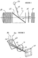
- Figure 1 is a diagrammatic side view of a portion of a LCLV projector.
- Light is transmitted from the illumination source 24 to the surface of polarizing surface 22.
- the illumination source is set at an angle of incidence that is 54.6° away from the normal angle 36.
- S-polarized light is reflected by the polarizing surface 22 through the quarter-wave plate 26 to the liquid crystal light valve 28. If the liquid crystal light valve is in the off state, it reflects the S-polarized light back through the quarter-wave plate to the polarizer which reflects the S-polarized light back in the direction of the illumination source 24.
- the LCLV 28 converts the S-polarized light to P-polarized light which is transferred through the quarter-wave plate 26 and through the polarizing surface 22 to the projection lens 20 which transfers the light to the projection screen (not shown).
- One aspect of the invention is the placement of a quarter-wave plate 26 between the polarizing surface and the LCLV.
- the quarter-wave plate 26 is tuned to the center wavelength of the spectrum of the Incident light so that the small chromatic errors of the quarter-wave plate are spectrally balanced.
- the quarter-wave plate 26 does not correct any local birefringence errors in the LCLV nor does it bias the starting point of the LCLV gamma curve.
- the quarter-wave plate corrects for small rotations of the polarization state of the S-polarized light (with respect to the LCLV) reflected from the polarizing surface 22.
- the quarter-wave plate cleans up geometrically induced factors in the polarizer as opposed to correcting problems with the LCLV. The details of this correction will be discussed further below.
- Figure 2 shows a perspective view of the polarizing surface 22, the quarter-wave plate 26 and the LCLV 28.
- the quarter-wave plate 26 is oriented so that its fast axis 32 is perpendicular to the axis of polarization of the polarizing surface 22. It should be noted at this point that the fast axis of the quarter-wave plate 26 can be either perpendicular or parallel to the axis of polarization of the polarizing surface because any P-polarized light will still have its phase shifted by 180°.
- any point on the active surface of the LCLV will see the same cone of light as partially represented by light rays 30a, 30b and 30c.
- Light ray 30b is in the center of the cone and is 100% S-polarized with respect to the planes of the quarter-wave plate 26 and the LCLV 28 as it is reflected from the polarizing surface 22.
- ray 30a has a small rotation in polarization direction due to the angle of incidence of the light on the polarizing surface 22.
- a higher degree of twist in the polarization axis occurs for a ray with a higher angle of incidence.
- the direction of rotation is dependent on the angle of incidence.
- a ray incident at 5° might rotate the polarization axis by 2° while a ray incident at -5° would rotate the polarization axis by -2°.
- ray 30a Since ray 30a is travelling to the polarization plate 22 from the illumination source 24 at a slight angle, it has a slight degree of P-polarization with respect to the polarization plate 22.
- the P-polarized light of ray 30a is passed through the polarizing surface 22 and the S-polarized component of ray 30a is reflected toward the quarter-wave plate with a slightly rotated plane of polarization with respect to the quarter-wave plate 26.
- Figure 3A is a diagram showing the effect of the quarter-wave plate on light having a large S component and a small P component.
- the quarter-wave plate has its fast axis perpendicular to the axis of polarization of the polarizing surface.
- Line 38 shows the phase of the light polarized in the S direction with respect to the axis of the quarter-wave plate.
- Line 40 shows the light polarized in the P direction with respect to the quarter-wave plate.
- Line 38 represents light polarized along the fast axis and line 40 represents light polarized along the slow axis.
- the phase of the P polarized light has been shifted by 90° after it has passed through the quarter-wave plate 26 shown in Figure 2.
- Figure 4A and Figure 5 represent light rays that are reflected without the use of the quarter-wave plate and Figures 4B and Figure 6 represent light that is reflected through a quarter-wave plate.
- incident ray 44 represents the ray on the edge of the light cone referred to previously.
- Arrow 46 represents the orientation of the polarization of ray 44 as it is reflected off of the polarizer 22.
- Arrows 48 and 50 represent respectively the S and P components of ray 44.
- the S and P components of exiting ray 52 are shown by arrows 54 and 56 respectively.
- Arrow 58 represents the combination of the S and P components 54 and 56.
- ray 52 After ray 52 is reflected from the LCLV 28, it strikes the polarizing surface 22 shown in Figure 5.
- the P component 56 of ray 52 has the same phase as P component 50 of ray 44. However, ray 52 is striking the polarizing surface at the reverse incident angle which means that a portion of ray 52 will be P-polarized with respect to the angle at which it strikes the polarizing surface 22. The P portion of ray 52 will then pass through the polarizer and raise the dark level of the projection screen.
- Figure 5 shows the same rays 44 and 52 as shown in Figure 4A from the prospective of the LCLV.
- ray 66 is shown as it is reflected off of the polarizer 22.
- Ray 66 has a polarization axis represented by arrow 68 and further represented arrows 70 and 72 which respectively represent the S-polarization and P-polarization components of ray 66.
- the arrow 72 is pointing up to indicate the phase orientation of the P component of ray 66.
- the phase of the P-polarized light is shifted by 90° as indicated by ellipse 76 which indicates that the phase arrow 74 is pointing counterclockwise.
- ray 66 is reflected off of LCLV 28, it is represented as ray 86.
- Figure 7 is a side view showing the layers of the liquid crystal light valve.
- the counter electrode 104 is supported by the counter electrode substrate 102.
- the counter electrode substrate 102 was constructed from Schott BK-7 Glass.
- the other layers of the light valve comprise counter electrode layer 104, alignment layer 106, liquid crystal layer 108, alignment layer 110, dieelectric layer 112, bonding layer 114, cadmium telluride layer 116, bonding layer 118, a-Si:H layer 120, SiO 2 layer 122, primary electrode layer 124, SiO 2 126 and primary electrode substrate layer 128.
- the counter electrode substrate layer 102 was normally constructed of Schott BK-7 Glass.
- a change in temperature does not directly change the refractive index of the material.
- the change causes dimensional change in the part through its thermal expansion coefficient. If the temperature is nonuniform or if the part is constrained the part will experience stress. This stress, in turn, causes a change in the refractive indices (parallel and perpendicular to the stress) through the photoelastic affect and the stress-optical coefficients.
- the difference in the refractive indices determines the birefringence which in turn determines the darkness of the dark state.
- the birefringence can be minimized by minimizing the thermal expansion coefficient or by finding stress-optical coefficients such that the difference in refractive indices is minimized.
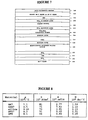
- Figure 8 is a calculation of a figure of merit that has been used to determine the suitability of materials for use as a counter electrode substrate in an environment of thermal heating and where a BK-7 primary substrate is being used.
- P is the thermal expansion coefficient
- E is the modulus of elasticity
- K is the stress-optical coefficient
- M index-difference temperature change.
- M pEK.
- SF-57 does have drawbacks in that it contains more bubbles than BK-7, ZKN7 or silica. However, it can be selected for very low bubble content for the size that will be useful in the present invention. Also SF-57 has poor acid resistance and must be coated on the exterior side. Therefore, by selecting SF-57 as the counter electrode substrate 102, the birefringence will be reduced over the thermal range of the LCLV. This is true because it reduces the amount of thermally induced stress birefringence. Therefore, by substituting SF-57 Glass for BK-7 Glass, the amount of birefringence thermally induced into the counter electrode substrate is reduced thereby increasing the contrast ratio and improving the quality of the projected images.
- a final aspect of the invention relates to adding a heat shield in front of the LCLV package to prevent heat from being absorbed into the counter electrode substrate 102 ( Figure 7) and the LCLV package in general.
- Figure 9 is a side view of the LCLV package showing the location of the heat shield.
- Figure 9 shows the front of the prism 130 which acts as the primary polarizer previously referred to above.
- the heat shield 132 also shown in Figure 10 as a top view, is anodized per MIL-A-8625 type II CL 2 black boiling water and not using sodium dichromate.
- the heat shield 132 has a rectangular area 162 in its approximate center allowing light rays 154, 158 and 160 to pass through to the counter electrode substrate 138.
- the counter electrode substrate 138 corresponds to the counter electrode substrate 102 in Figure 7.
- Stray light rays 152 pass out of the main polarizer 130 and strike the black anodized surface of the heat shield 132. The absorption of this light causes the temperature of the heat shield to rise.
- the heat shield is cooled by a fan (not shown) that blows air through air gaps 148 and 150 which are approximately .030" wide. This passing air causes heat to be removed from the heat shield 132.
- Heat shield 132 is attached to the dust cover 146 and the aperture 136. The aperture and dust cover are anodized in the same manner as the heat shield.
- the heat shield 132 With the heat shield 132 in place, stray light 152 is blocked, absorbed and removed and illumination light from the polarizer is allowed to pass through opening 162 ( Figure 10) and impinge upon the counter electrode 138.
- the rectangular open space 162 of the heat shield 132 is slightly larger than the rectangular opening of the aperture plate 136 in order to improve the quality of the image transferred by the edges of the liquid crystal light valve.
- the opening 162 of the heat shield 132 is calculated by using the cone angle of the optical system which gives the angle of approximately 5° as shown by angle 156 with ray 164 being normal to the surface plane of the counter electrode substrate 138.
- the absorption of the stray light 152 by the heat shield 132 also prevents heating of the aperture mask 136 which in turn avoids heat of the counter electrode 138.
- the heat shield 132 was designed to eliminate heating of the aperture 136 by stray light. To further enhance heat transfer from the aperture mask 136 to the cover glass frame 146, the aperture mask 136 to cover glass frame contact is not anodized.
Landscapes
- Physics & Mathematics (AREA)
- Nonlinear Science (AREA)
- Mathematical Physics (AREA)
- Chemical & Material Sciences (AREA)
- Crystallography & Structural Chemistry (AREA)
- General Physics & Mathematics (AREA)
- Optics & Photonics (AREA)
- Liquid Crystal (AREA)
- Projection Apparatus (AREA)
Claims (19)
- Projektionssystem auf Polarisationsbasis, das aufweist:eine Lichtquelle (24) zum Erzeugen von Beleuchtungslicht,eine Polarisationseinrichtung (22), die angrenzend an die Beleuchtungseinrichtung angeordnet ist, um von der Lichtquelle ausgehendes polarisiertes Licht zu lenken,eine angrenzend an die Polarisationseinrichtung angeordnete Flüssigkristall-Lichtventileinrichtung (28) zum Empfang von polarisiertem Licht, das von der Polarisationseinrichtung reflektiert wird, wobei das Flüssigkristall-Lichtventil imstande ist, den Polarisationszustand des von der Polarisationseinrichtung reflektierten polarisierten Beleuchtungslichts zu ändern,eine Projektionslinse (20) zur Projektion von Licht, das von der Flüssigkristall-Lichtventileinrichtung durch die Polarisationseinrichtung zur Projektionslinse übertragen wird, um ein Bild auf einen Bildschirm zu projizieren,eine zwischen der Polarisationseinrichtung und der Flüssigkristall-Lichtventileinrichtung angeordnete Kompensatoreinrichtung (26) zur Veränderung des Phasenwinkels des polarisierten Lichts, das von der Polarisationseinrichtung durch die Kompensatoreinrichtung zur Flüssigkristall-Lichtventileinrichtung und zurück durch die Kompensatoreinrichtung zur Polarisationseinrichtung reflektiert wird, wobei die Kompensatoreinrichtung die Polarisation des reflektierten Lichts so verschoben hat, daß das reflektierte Licht in seiner Polarisation eine Phasenverschiebung von annähernd 180° aufweist, dadurch gekennzeichnet, daßdie Kompensatoreinrichtung (26) einen Gesamtgangunterschied von mehr als 0,25 aufweist, wobei der zusätzliche Gangunterschied über 0,25 die Doppelbrechung in der Flüssigkristall-Lichtventileinrichtung kompensiert.
- Projektionssystem auf Polarisationsbasis nach Anspruch 1, wobei die Kompensatoreinrichtung (26) ein Wellenplättchen ist.
- Projektionssystem auf Polarisationsbasis nach Anspruch 2, wobei das Wellenplättchen einen Gesamtgangunterschied von 0,27 aufweist, wobei der zusätzliche Gangunterschied von 0,02 dazu bestimmt ist, die Doppelbrechung in der Flüssigkristall-Lichtventileinrichtung zu kompensieren.
- Projektionssystem auf Polarisationsbasis nach Anspruch 1, wobei die schnelle Achse der Kompensatoreinrichtung senkrecht oder parallel zur Polarisationsachse der Polarisationseinrichtung liegt.
- Projektionssystem auf Polarisationsbasis nach Anspruch 1, wobei die Flüssigkristall-Lichtventileinrichtung ein Elektrodensubstrat mit geringer thermisch induzierter Spannungsdoppelbrechung und niedrigem spannungsoptischem Koeffizienten aufweist.
- Projektionssystem auf Polarisationsbasis nach Anspruch 5, wobei das Elektrodensubstrat aus SF-57-Glas besteht.
- Projektionssystem auf Polarisationsbasis nach Anspruch 5, wobei die Kompensatoreinrichtung ein Wellenplättchen ist.
- Projektionssystem auf Polarisationsbasis nach Anspruch 7, wobei das Wellenplättchen einen Gesamtgangunterschied von 0,27 aufweist, wobei der zusätzliche Gangunterschied von 0,02 dazu bestimmt ist, die Doppelbrechung in der Flüssigkristall-Lichtventileinrichtung zu kompensieren.
- Projektionssystem auf Polarisationsbasis, das aufweist:eine Lichtquelle (24) zum Erzeugen von Beleuchtungslicht,eine Polarisationseinrichtung (22), die angrenzend an die Beleuchtungseinrichtung angeordnet ist, um von der Lichtquelle ausgehendes polarisiertes Licht zu lenken,eine angrenzend an die Polarisationseinrichtung angeordnete Flüssigkristall-Lichtventileinrichtung (28) zum Empfang von polarisiertem Licht, das von der Polarisationseinrichtung reflektiert wird, wobei das Flüssigkristall-Lichtventil imstande ist, den Polarisationszustand des von der Polarisationseinrichtung reflektierten polarisierten Beleuchtungslichts zu ändern,eine Projektionslinse (20) zur Projektion von Licht, das von der Flüssigkristall-Lichtventileinrichtung durch die Polarisationseinrichtung zur Projektionslinse übertragen wird, um ein Bild auf einen Bildschirm zu projizieren, gekennzeichnet durcheine zwischen der Polarisationseinrichtung und der Flüssigkristall-Lichtventileinrichtung angeordnete Wärmeabschirmungseinrichtung (132) zur Absorption von Streulicht (152) und zur Verminderung der auf die Flüssigkristall-Lichtventilpackung übertragenen Temperatur, wodurch die Doppelbrechung des Flüssigkristall-Lichtventils vermindert wird.
- Projektionssystem auf Polarisationsbasis nach Anspruch 9, die eine zwischen der Polarisationseinrichtung und der Flüssigkristall-Lichtventileinrichtung angeordnete Kompensatoreinrichtung (26) aufweist, um den Phasenwinkel des polarisierten Lichts zu ändern, das von der Polarisationseinrichtung durch die Kompensatoreinrichtung zu der Flüssigkristall-Lichtventileinrichtung und zurück durch die Kompensatoreinrichtung zur Polarisationseinrichtung reflektiert wird, wobei die Kompensatoreinrichtung die P-Polarisation des reflektierten Lichts so verschoben hat, daß das reflektierte Licht in seiner P-Polarisation eine Phasenverschiebung von annähernd 180° aufweist.
- Projektionssystem auf Polarisationsbasis nach Anspruch 10, wobei die Flüssigkristall-Lichtventileinrichtung ein Elektrodensubstrat mit geringer thermisch induzierter Spannungsdoppelbrechung und niedrigem spannungsoptischem Koeffizienten aufweist.
- Projektionssystem auf Polarisationsbasis nach Anspruch 11, wobei das Substrat aus SF-57-Glas besteht.
- Projektionssystem auf Polarisationsbasis nach Anspruch 12, wobei die Kompensatoreinrichtung ein Wellenplättchen ist.
- Projektionssystem auf Polarisationsbasis nach Anspruch 10, wobei die Kompensatoreinrichtung einen Gesamtgangunterschied von mehr als 0,25 aufweist,
wobei der zusätzliche Gangunterschied über 0,25 die Doppelbrechung in der Flüssigkristall-Lichtventileinrichtung kompensiert. - Projektionssystem auf Polarisationsbasis, das aufweist:eine Beleuchtungslichtquelle (24),eine Polarisationseinrichtung (22) zum Empfang des Lichts, um daraus polarisiertes Licht zu erzeugen;ein angrenzend an die Polarisationseinrichtung angeordnetes Flüssigkristall-Lichtventil zum Modulieren des polarisierten Lichts; gekennzeichnet durcheine zwischen dem Lichtventil und der Polarisationseinrichtung angeordnete Wärmeabschirmung (132), die einen äußeren Abschnitt aufweist, der eine erste Öffnung (162) definiert, wobei die erste Öffnung zur Übertragung von einfallendem Licht zu dem Lichtventil dient und der äußere Abschnitt zur Absorption von Streulicht dient, um die Temperatur und die Doppelbrechung des Lichtventils zu verringern.
- Projektionssystem auf Polarisationsbasis nach Anspruch 15, das ferner aufweist:wobei die erste Öffnung größer als die zweite Öffnung ist und die Wärmeabschirmung die Erwärmung der Aperturblende vermindert.eine Aperturblende (136), die eine zweite Öffnung definiert und zwischen dem Lichtventil und der Wärmeabschirmung angebracht ist,
- Projektionssystem auf Polarisationsbasis nach Anspruch 15, wobei der Größenunterschied zwischen der ersten und der zweiten Öffnung in Beziehung zu einem Öffnungswinkel des durch die Lichtquelle erzeugten Lichtkegels steht.
- Projektionssystem auf Polarisationsbasis nach Anspruch 15, wobei der äußere Abschnitt der Wärmeabschirmung eloxiert ist.
- Projektionssystem auf Polarisationsbasis nach Anspruch 15, das ferner eine Staubschutzhaube aufweist, wobei die Wärmeabschirmung und die Aperturblende mit der Staubschutzhaube verbunden sind.
Applications Claiming Priority (3)
| Application Number | Priority Date | Filing Date | Title |
|---|---|---|---|
| US08/152,996 US5576854A (en) | 1993-11-12 | 1993-11-12 | Liquid crystal light valve projector with improved contrast ratio and with 0.27 wavelength compensation for birefringence in the liquid crystal light valve |
| US152996 | 1993-11-12 | ||
| PCT/US1994/012289 WO1995013561A1 (en) | 1993-11-12 | 1994-10-26 | Liquid crystal light valve projection system with compensator means and counter electrode substrate composition |
Publications (3)
| Publication Number | Publication Date |
|---|---|
| EP0729596A1 EP0729596A1 (de) | 1996-09-04 |
| EP0729596A4 EP0729596A4 (de) | 1997-05-02 |
| EP0729596B1 true EP0729596B1 (de) | 2002-02-27 |
Family
ID=22545354
Family Applications (1)
| Application Number | Title | Priority Date | Filing Date |
|---|---|---|---|
| EP94932055A Expired - Lifetime EP0729596B1 (de) | 1993-11-12 | 1994-10-26 | Projektionssystem mit flüssigkristall-lichtventil und kompensationseinrichtung sowie zusammensetzung des gegenelektrodensubstrat |
Country Status (5)
| Country | Link |
|---|---|
| US (1) | US5576854A (de) |
| EP (1) | EP0729596B1 (de) |
| JP (1) | JP3326614B2 (de) |
| DE (1) | DE69430000T2 (de) |
| WO (1) | WO1995013561A1 (de) |
Families Citing this family (97)
| Publication number | Priority date | Publication date | Assignee | Title |
|---|---|---|---|---|
| US5910854A (en) | 1993-02-26 | 1999-06-08 | Donnelly Corporation | Electrochromic polymeric solid films, manufacturing electrochromic devices using such solid films, and processes for making such solid films and devices |
| USRE38488E1 (en) * | 1994-01-28 | 2004-04-06 | Matsushita Electric Industrial Co., Ltd. | Optical system including a reflecting polarizer for a rear projection picture display apparatus |
| US5668663A (en) | 1994-05-05 | 1997-09-16 | Donnelly Corporation | Electrochromic mirrors and devices |
| US6227670B1 (en) | 1995-03-06 | 2001-05-08 | Nikon Corporation | Projection type display apparatus |
| US6062694A (en) * | 1995-03-06 | 2000-05-16 | Nikon Corporation | Projection type display apparatus |
| US5808795A (en) * | 1995-03-06 | 1998-09-15 | Nikon Corporation | Projection type display apparatus |
| US6005644A (en) * | 1995-03-08 | 1999-12-21 | Seiko Epson Corporation | Projection display employing circular polarized light for reflection reduction |
| US6891563B2 (en) | 1996-05-22 | 2005-05-10 | Donnelly Corporation | Vehicular vision system |
| EP0880279B1 (de) | 1997-05-20 | 2001-08-01 | Barco N.V. | Kontrastverbesserung bei Bildprojektoren mit Flüssigkristalllichtventil |
| US5973760A (en) * | 1997-08-06 | 1999-10-26 | Rockwell Science Center, Inc. | Display apparatus having quarter-wave plate positioned to eliminate conflicts with polarized sunglasses |
| US6124886A (en) | 1997-08-25 | 2000-09-26 | Donnelly Corporation | Modular rearview mirror assembly |
| US8294975B2 (en) | 1997-08-25 | 2012-10-23 | Donnelly Corporation | Automotive rearview mirror assembly |
| US6326613B1 (en) | 1998-01-07 | 2001-12-04 | Donnelly Corporation | Vehicle interior mirror assembly adapted for containing a rain sensor |
| US6172613B1 (en) | 1998-02-18 | 2001-01-09 | Donnelly Corporation | Rearview mirror assembly incorporating vehicle information display |
| US5973833A (en) * | 1997-08-29 | 1999-10-26 | Lightware, Inc. | High efficiency polarizing converter |
| US6445287B1 (en) | 2000-02-28 | 2002-09-03 | Donnelly Corporation | Tire inflation assistance monitoring system |
| US8288711B2 (en) | 1998-01-07 | 2012-10-16 | Donnelly Corporation | Interior rearview mirror system with forwardly-viewing camera and a control |
| US6329925B1 (en) | 1999-11-24 | 2001-12-11 | Donnelly Corporation | Rearview mirror assembly with added feature modular display |
| US6477464B2 (en) | 2000-03-09 | 2002-11-05 | Donnelly Corporation | Complete mirror-based global-positioning system (GPS) navigation solution |
| US6693517B2 (en) | 2000-04-21 | 2004-02-17 | Donnelly Corporation | Vehicle mirror assembly communicating wirelessly with vehicle accessories and occupants |
| US5986815A (en) * | 1998-05-15 | 1999-11-16 | Optical Coating Laboratory, Inc. | Systems, methods and apparatus for improving the contrast ratio in reflective imaging systems utilizing color splitters |
| US6233084B1 (en) * | 1999-07-28 | 2001-05-15 | Hewlett-Packard Company | Optical display system including an achromatized ferroelectric light valve |
| US7306338B2 (en) | 1999-07-28 | 2007-12-11 | Moxtek, Inc | Image projection system with a polarizing beam splitter |
| US6398364B1 (en) | 1999-10-06 | 2002-06-04 | Optical Coating Laboratory, Inc. | Off-axis image projection display system |
| US6722768B1 (en) * | 1999-10-06 | 2004-04-20 | Seiko Epson Corporation | Projector |
| IL132928A0 (en) * | 1999-11-14 | 2001-03-19 | Unic View Ltd | Thermally stable birefringent prism assembly |
| US6781640B1 (en) | 1999-11-15 | 2004-08-24 | Sharp Laboratories Of America, Inc. | Projection display having polarization compensator |
| US7370983B2 (en) | 2000-03-02 | 2008-05-13 | Donnelly Corporation | Interior mirror assembly with display |
| US7167796B2 (en) | 2000-03-09 | 2007-01-23 | Donnelly Corporation | Vehicle navigation system for use with a telematics system |
| AU2001243285A1 (en) | 2000-03-02 | 2001-09-12 | Donnelly Corporation | Video mirror systems incorporating an accessory module |
| US6340230B1 (en) | 2000-03-10 | 2002-01-22 | Optical Coating Laboratory, Inc. | Method of using a retarder plate to improve contrast in a reflective imaging system |
| US6563551B1 (en) | 2000-06-28 | 2003-05-13 | Koninklijke Philips Electronics N.V. | High contrast polarizing optics for a color electro-optic display device |
| US6833894B2 (en) * | 2001-01-11 | 2004-12-21 | Hana Microdisplay Technologies, Inc | Enhanced contrast ratio for twisted nematic liquid crystal devices |
| JP2002207213A (ja) | 2001-01-11 | 2002-07-26 | Hitachi Ltd | 液晶表示素子又はそれを用いた表示装置 |
| DE60239446D1 (de) * | 2001-01-15 | 2011-04-28 | Seiko Epson Corp | Projektor |
| US7255451B2 (en) | 2002-09-20 | 2007-08-14 | Donnelly Corporation | Electro-optic mirror cell |
| US7581859B2 (en) | 2005-09-14 | 2009-09-01 | Donnelly Corp. | Display device for exterior rearview mirror |
| WO2002062623A2 (en) | 2001-01-23 | 2002-08-15 | Donnelly Corporation | Improved vehicular lighting system for a mirror assembly |
| US7027224B2 (en) | 2001-01-31 | 2006-04-11 | Sharp Laboratories Of America, Inc. | Wave plate mounting |
| US6585378B2 (en) | 2001-03-20 | 2003-07-01 | Eastman Kodak Company | Digital cinema projector |
| US6626539B2 (en) * | 2001-04-30 | 2003-09-30 | Koninklijke Philips Electronics N.V. | Color video projection display system with low-retardance compensator film for improved contrast |
| US6785051B2 (en) * | 2001-07-18 | 2004-08-31 | Corning Incorporated | Intrinsic birefringence compensation for below 200 nanometer wavelength optical lithography components with cubic crystalline structures |
| US6909473B2 (en) * | 2002-01-07 | 2005-06-21 | Eastman Kodak Company | Display apparatus and method |
| US7061561B2 (en) * | 2002-01-07 | 2006-06-13 | Moxtek, Inc. | System for creating a patterned polarization compensator |
| JP2003222724A (ja) | 2002-01-31 | 2003-08-08 | Hitachi Ltd | 1/4波長板、光学ユニット、及びそれを用いた反射型液晶表示装置 |
| US6712472B2 (en) * | 2002-02-13 | 2004-03-30 | Sharp Laboratories Of America, Inc. | Color field sequential projector including polarized light beam splitter and electronically controllable birefringence quarter waveplate |
| MXPA04008145A (es) * | 2002-02-28 | 2004-11-26 | 3M Innovative Properties Co | Divisores compuestos de haces de polarizacion. |
| JP3970055B2 (ja) * | 2002-02-28 | 2007-09-05 | キヤノン株式会社 | 液晶表示装置 |
| TW554233B (en) | 2002-03-01 | 2003-09-21 | Victor Company Of Japan | Reflective liquid crystal projection apparatus |
| US7046320B2 (en) * | 2002-03-14 | 2006-05-16 | Nitto Denko Corporation | Optical element and surface light source device using the same, as well as liquid crystal display |
| US6918674B2 (en) | 2002-05-03 | 2005-07-19 | Donnelly Corporation | Vehicle rearview mirror system |
| US7131737B2 (en) * | 2002-06-05 | 2006-11-07 | Moxtek, Inc. | Housing for mounting a beamsplitter and a spatial light modulator with an output optical path |
| US6805445B2 (en) | 2002-06-05 | 2004-10-19 | Eastman Kodak Company | Projection display using a wire grid polarization beamsplitter with compensator |
| US7329013B2 (en) | 2002-06-06 | 2008-02-12 | Donnelly Corporation | Interior rearview mirror system with compass |
| AU2003237424A1 (en) | 2002-06-06 | 2003-12-22 | Donnelly Corporation | Interior rearview mirror system with compass |
| EP1543358A2 (de) | 2002-09-20 | 2005-06-22 | Donnelly Corporation | Spiegelreflexionselementbaugruppe |
| WO2004103772A2 (en) | 2003-05-19 | 2004-12-02 | Donnelly Corporation | Mirror assembly for vehicle |
| US7310177B2 (en) | 2002-09-20 | 2007-12-18 | Donnelly Corporation | Electro-optic reflective element assembly |
| KR20050067216A (ko) * | 2002-11-01 | 2005-06-30 | 코핀 코포레이션 | 다중-영역의 수직 정렬 액정 디스플레이 |
| JP4359105B2 (ja) * | 2003-08-25 | 2009-11-04 | 株式会社日立製作所 | 液晶パネル装置 |
| US7446924B2 (en) | 2003-10-02 | 2008-11-04 | Donnelly Corporation | Mirror reflective element assembly including electronic component |
| US7308341B2 (en) | 2003-10-14 | 2007-12-11 | Donnelly Corporation | Vehicle communication system |
| JP2005128216A (ja) * | 2003-10-23 | 2005-05-19 | Nitto Denko Corp | 旋光板、光学素子、集光バックライトシステムおよび液晶表示装置 |
| US7142340B2 (en) * | 2003-10-31 | 2006-11-28 | Hewlett-Packard Development Company, L.P. | Optical scanner apparatuses and optical scanning methods |
| WO2005045507A1 (en) * | 2003-11-06 | 2005-05-19 | Koninklijke Philips Electronics, N.V. | Projection system |
| WO2005057939A1 (en) * | 2003-12-12 | 2005-06-23 | Universiteit Gent | Method and system for guiding light in a multicolour projector |
| US6902277B1 (en) | 2004-01-06 | 2005-06-07 | Eastman Kodak Company | Housing for a spatial light modulator |
| US7165843B2 (en) * | 2004-02-03 | 2007-01-23 | Aurora Systems, Inc. | Optical system with angular compensator |
| US7564522B2 (en) * | 2004-05-21 | 2009-07-21 | Kopin Corporation | Full symmetrical wide-viewing angle display |
| US7961393B2 (en) | 2004-12-06 | 2011-06-14 | Moxtek, Inc. | Selectively absorptive wire-grid polarizer |
| US7570424B2 (en) | 2004-12-06 | 2009-08-04 | Moxtek, Inc. | Multilayer wire-grid polarizer |
| US7630133B2 (en) | 2004-12-06 | 2009-12-08 | Moxtek, Inc. | Inorganic, dielectric, grid polarizer and non-zero order diffraction grating |
| US7800823B2 (en) | 2004-12-06 | 2010-09-21 | Moxtek, Inc. | Polarization device to polarize and further control light |
| US7357511B2 (en) * | 2005-03-23 | 2008-04-15 | 3M Innovative Properties Company | Stress birefringence compensation in polarizing beamsplitters and systems using same |
| ATE517368T1 (de) | 2005-05-16 | 2011-08-15 | Donnelly Corp | Fahrzeugspiegelanordnung mit zeichen am reflektierenden teil |
| US20060274276A1 (en) * | 2005-06-01 | 2006-12-07 | Lightmaster Systems, Inc. | Method and apparatus for precisely compensating skew rays and residual retardation |
| EP1949666B1 (de) | 2005-11-01 | 2013-07-17 | Magna Mirrors of America, Inc. | Innen-rückspiegel mit display |
| US8755113B2 (en) | 2006-08-31 | 2014-06-17 | Moxtek, Inc. | Durable, inorganic, absorptive, ultra-violet, grid polarizer |
| US7789515B2 (en) | 2007-05-17 | 2010-09-07 | Moxtek, Inc. | Projection device with a folded optical path and wire-grid polarizer |
| US20090002579A1 (en) | 2007-06-29 | 2009-01-01 | Jds Uniphase Corporation | Near Halfwave Retarder For Contrast Compensation |
| US8154418B2 (en) | 2008-03-31 | 2012-04-10 | Magna Mirrors Of America, Inc. | Interior rearview mirror system |
| US9487144B2 (en) | 2008-10-16 | 2016-11-08 | Magna Mirrors Of America, Inc. | Interior mirror assembly with display |
| US8248696B2 (en) | 2009-06-25 | 2012-08-21 | Moxtek, Inc. | Nano fractal diffuser |
| US8305502B2 (en) | 2009-11-11 | 2012-11-06 | Eastman Kodak Company | Phase-compensated thin-film beam combiner |
| US8649094B2 (en) | 2010-05-21 | 2014-02-11 | Eastman Kodak Company | Low thermal stress birefringence imaging lens |
| US8287129B2 (en) | 2010-05-21 | 2012-10-16 | Eastman Kodak Company | Low thermal stress birefringence imaging system |
| US8504328B2 (en) | 2010-05-21 | 2013-08-06 | Eastman Kodak Company | Designing lenses using stress birefringence performance criterion |
| US8611007B2 (en) | 2010-09-21 | 2013-12-17 | Moxtek, Inc. | Fine pitch wire grid polarizer |
| US8913321B2 (en) | 2010-09-21 | 2014-12-16 | Moxtek, Inc. | Fine pitch grid polarizer |
| JP5170207B2 (ja) * | 2010-10-20 | 2013-03-27 | 株式会社Jvcケンウッド | 分布型補償器および投射型液晶表示装置 |
| US8913320B2 (en) | 2011-05-17 | 2014-12-16 | Moxtek, Inc. | Wire grid polarizer with bordered sections |
| US8873144B2 (en) | 2011-05-17 | 2014-10-28 | Moxtek, Inc. | Wire grid polarizer with multiple functionality sections |
| US8786943B2 (en) | 2011-10-27 | 2014-07-22 | Eastman Kodak Company | Low thermal stress catadioptric imaging system |
| US8830580B2 (en) | 2011-10-27 | 2014-09-09 | Eastman Kodak Company | Low thermal stress catadioptric imaging optics |
| US8922890B2 (en) | 2012-03-21 | 2014-12-30 | Moxtek, Inc. | Polarizer edge rib modification |
| US9354374B2 (en) | 2013-10-24 | 2016-05-31 | Moxtek, Inc. | Polarizer with wire pair over rib |
| TWI826607B (zh) * | 2018-12-07 | 2023-12-21 | 美商思娜公司 | 顯示系統、空間光調變器系統及顯示系統的形成方法 |
Family Cites Families (17)
| Publication number | Priority date | Publication date | Assignee | Title |
|---|---|---|---|---|
| DE7538264U (de) * | 1974-12-02 | 1977-09-22 | Revue Thommen Ag, Waldenburg (Schweiz) | Lichtschutzfilter |
| US4408839A (en) * | 1981-04-01 | 1983-10-11 | Hughes Aircraft Company | Twisted nematic liquid light valve with birefringence compensation |
| US4466702A (en) * | 1981-04-01 | 1984-08-21 | Hughes Aircraft Company | Liquid crystal light valve with birefringence compensation |
| US4464018A (en) * | 1981-12-28 | 1984-08-07 | Hughes Aircraft Company | Liquid crystal light valve image projection system with color selective prepolarization and blue mirror |
| US4687301A (en) * | 1985-07-12 | 1987-08-18 | Hughes Aircraft Company | Full-color projector system with a tricolor-separating prism |
| DE8805355U1 (de) * | 1988-04-22 | 1988-06-01 | Kodak Ag, 7000 Stuttgart | Überkopfprojektor |
| US5042921A (en) * | 1988-10-25 | 1991-08-27 | Casio Computer Co., Ltd. | Liquid crystal display apparatus |
| JPH0738050B2 (ja) * | 1989-03-23 | 1995-04-26 | 松下電器産業株式会社 | 偏光ビームスプリッタ装置とその装置を用いたライトバルブ光学装置 |
| US5327270A (en) * | 1989-03-23 | 1994-07-05 | Matsushita Electric Industrial Co., Ltd. | Polarizing beam splitter apparatus and light valve image projection system |
| US5121245A (en) * | 1989-04-06 | 1992-06-09 | Electro Scientific Industries, Inc. | Laser system incorporating an acousto-optic device having reduced susceptibility to stress-induced birefringence |
| JPH0384538A (ja) * | 1989-08-29 | 1991-04-10 | Canon Inc | 投射型表示装置 |
| EP0434041B1 (de) * | 1989-12-20 | 1996-09-11 | Canon Kabushiki Kaisha | Polarisierendes Beleuchtungsgerät |
| KR920010809B1 (ko) * | 1990-05-19 | 1992-12-17 | 주식회사 금성사 | Lcd 프로젝터의 광학 시스템 |
| FR2673006B1 (fr) * | 1991-02-19 | 1993-10-22 | Hughes Aircraft Cy | Systeme de projection a reflexion a valve de lumiere a cristal liquide. |
| DE69218830T2 (de) * | 1991-05-29 | 1997-07-17 | Matsushita Electric Ind Co Ltd | Bildprojektions-System |
| US5229872A (en) * | 1992-01-21 | 1993-07-20 | Hughes Aircraft Company | Exposure device including an electrically aligned electronic mask for micropatterning |
| JP3192251B2 (ja) * | 1992-12-02 | 2001-07-23 | パイオニア株式会社 | 反射型液晶表示装置 |
-
1993
- 1993-11-12 US US08/152,996 patent/US5576854A/en not_active Expired - Lifetime
-
1994
- 1994-10-26 WO PCT/US1994/012289 patent/WO1995013561A1/en not_active Ceased
- 1994-10-26 DE DE69430000T patent/DE69430000T2/de not_active Expired - Lifetime
- 1994-10-26 JP JP51385795A patent/JP3326614B2/ja not_active Expired - Lifetime
- 1994-10-26 EP EP94932055A patent/EP0729596B1/de not_active Expired - Lifetime
Also Published As
| Publication number | Publication date |
|---|---|
| JPH09508709A (ja) | 1997-09-02 |
| EP0729596A4 (de) | 1997-05-02 |
| DE69430000D1 (de) | 2002-04-04 |
| DE69430000T2 (de) | 2002-09-26 |
| EP0729596A1 (de) | 1996-09-04 |
| US5576854A (en) | 1996-11-19 |
| WO1995013561A1 (en) | 1995-05-18 |
| JP3326614B2 (ja) | 2002-09-24 |
Similar Documents
| Publication | Publication Date | Title |
|---|---|---|
| EP0729596B1 (de) | Projektionssystem mit flüssigkristall-lichtventil und kompensationseinrichtung sowie zusammensetzung des gegenelektrodensubstrat | |
| WO1995013561A9 (en) | Liquid crystal light valve projection system with compensator means and counter electrode substrate composition | |
| US7575325B2 (en) | Image displaying apparatus and color separating-combining optical system | |
| US5570215A (en) | Liquid crystal display apparatus and projection displaying apparatus having a rotatable phase difference plate and polarizer | |
| US6340230B1 (en) | Method of using a retarder plate to improve contrast in a reflective imaging system | |
| TWI409571B (zh) | 用以安裝光束分離器與空間光之調變器之殼體及用於一光學組件之殼體裝置 | |
| US6885422B2 (en) | Apparatus and method for displaying image | |
| EP0333333B1 (de) | Anzeigevorrichtung | |
| US7061561B2 (en) | System for creating a patterned polarization compensator | |
| US6795243B1 (en) | Polarizing light pipe | |
| US20050190445A1 (en) | Wire grid polarizer | |
| WO1993025922A1 (en) | Method and means for reflecting a predetermined range of wavelengths of a beam of light | |
| US5459593A (en) | Reflection type liquid crystal display apparatus which prevents rotation of the polarization plane | |
| EP1289312B1 (de) | Optischer Farbenteiler, optisches System zur Bildanzeige und Projektionsbildanzeigegerät | |
| CA2336553C (en) | Liquid crystal projector device | |
| JP2003255330A (ja) | 液晶表示装置 | |
| US5902031A (en) | Projection color image display apparatus | |
| JP2007304607A (ja) | 投写型表示装置 | |
| JP3437919B2 (ja) | 反射型プロジェクター | |
| JP3643658B2 (ja) | 光書込反射型空間光変調器 | |
| US11754882B2 (en) | Optical compensation device and liquid crystal display device | |
| CN1979331A (zh) | 投影显示设备 | |
| US5999246A (en) | Image recording apparatus with improved spatial light modulator | |
| JP3708921B2 (ja) | 液晶プロジェクタ | |
| JPH0973128A (ja) | 液晶プロジェクタ装置 |
Legal Events
| Date | Code | Title | Description |
|---|---|---|---|
| PUAI | Public reference made under article 153(3) epc to a published international application that has entered the european phase |
Free format text: ORIGINAL CODE: 0009012 |
|
| 17P | Request for examination filed |
Effective date: 19960426 |
|
| AK | Designated contracting states |
Kind code of ref document: A1 Designated state(s): DE FR GB |
|
| A4 | Supplementary search report drawn up and despatched |
Effective date: 19970310 |
|
| AK | Designated contracting states |
Kind code of ref document: A4 Designated state(s): DE FR GB |
|
| GRAG | Despatch of communication of intention to grant |
Free format text: ORIGINAL CODE: EPIDOS AGRA |
|
| RAP1 | Party data changed (applicant data changed or rights of an application transferred) |
Owner name: VICTOR COMPANY OF JAPAN, LIMITED |
|
| 17Q | First examination report despatched |
Effective date: 20010321 |
|
| GRAG | Despatch of communication of intention to grant |
Free format text: ORIGINAL CODE: EPIDOS AGRA |
|
| GRAG | Despatch of communication of intention to grant |
Free format text: ORIGINAL CODE: EPIDOS AGRA |
|
| GRAH | Despatch of communication of intention to grant a patent |
Free format text: ORIGINAL CODE: EPIDOS IGRA |
|
| GRAH | Despatch of communication of intention to grant a patent |
Free format text: ORIGINAL CODE: EPIDOS IGRA |
|
| REG | Reference to a national code |
Ref country code: GB Ref legal event code: IF02 |
|
| GRAA | (expected) grant |
Free format text: ORIGINAL CODE: 0009210 |
|
| AK | Designated contracting states |
Kind code of ref document: B1 Designated state(s): DE FR GB |
|
| REF | Corresponds to: |
Ref document number: 69430000 Country of ref document: DE Date of ref document: 20020404 |
|
| ET | Fr: translation filed | ||
| PLBE | No opposition filed within time limit |
Free format text: ORIGINAL CODE: 0009261 |
|
| STAA | Information on the status of an ep patent application or granted ep patent |
Free format text: STATUS: NO OPPOSITION FILED WITHIN TIME LIMIT |
|
| 26N | No opposition filed |
Effective date: 20021128 |
|
| REG | Reference to a national code |
Ref country code: DE Ref legal event code: R081 Ref document number: 69430000 Country of ref document: DE Owner name: JVC KENWOOD CORPORATION, YOKOHAMA-SHI, JP Free format text: FORMER OWNER: VICTOR COMPANY OF JAPAN, LTD., YOKOHAMA, KANAGAWA, JP Effective date: 20120430 |
|
| REG | Reference to a national code |
Ref country code: FR Ref legal event code: TP Owner name: JVC KENWOOD CORPORATION, JP Effective date: 20120705 |
|
| PGFP | Annual fee paid to national office [announced via postgrant information from national office to epo] |
Ref country code: FR Payment date: 20131009 Year of fee payment: 20 Ref country code: GB Payment date: 20131023 Year of fee payment: 20 Ref country code: DE Payment date: 20131023 Year of fee payment: 20 |
|
| REG | Reference to a national code |
Ref country code: DE Ref legal event code: R071 Ref document number: 69430000 Country of ref document: DE |
|
| REG | Reference to a national code |
Ref country code: GB Ref legal event code: PE20 Expiry date: 20141025 |
|
| PG25 | Lapsed in a contracting state [announced via postgrant information from national office to epo] |
Ref country code: GB Free format text: LAPSE BECAUSE OF EXPIRATION OF PROTECTION Effective date: 20141025 |