EP0729407B1 - Systeme et procede d'emballage - Google Patents
Systeme et procede d'emballage Download PDFInfo
- Publication number
- EP0729407B1 EP0729407B1 EP95902626A EP95902626A EP0729407B1 EP 0729407 B1 EP0729407 B1 EP 0729407B1 EP 95902626 A EP95902626 A EP 95902626A EP 95902626 A EP95902626 A EP 95902626A EP 0729407 B1 EP0729407 B1 EP 0729407B1
- Authority
- EP
- European Patent Office
- Prior art keywords
- cushioning
- assembly
- length
- pad
- machine
- Prior art date
- Legal status (The legal status is an assumption and is not a legal conclusion. Google has not performed a legal analysis and makes no representation as to the accuracy of the status listed.)
- Expired - Lifetime
Links
Images


Classifications
-
- B—PERFORMING OPERATIONS; TRANSPORTING
- B31—MAKING ARTICLES OF PAPER, CARDBOARD OR MATERIAL WORKED IN A MANNER ANALOGOUS TO PAPER; WORKING PAPER, CARDBOARD OR MATERIAL WORKED IN A MANNER ANALOGOUS TO PAPER
- B31D—MAKING ARTICLES OF PAPER, CARDBOARD OR MATERIAL WORKED IN A MANNER ANALOGOUS TO PAPER, NOT PROVIDED FOR IN SUBCLASSES B31B OR B31C
- B31D5/00—Multiple-step processes for making three-dimensional articles ; Making three-dimensional articles
- B31D5/0039—Multiple-step processes for making three-dimensional articles ; Making three-dimensional articles for making dunnage or cushion pads
- B31D5/0043—Multiple-step processes for making three-dimensional articles ; Making three-dimensional articles for making dunnage or cushion pads including crumpling flat material
- B31D5/0047—Multiple-step processes for making three-dimensional articles ; Making three-dimensional articles for making dunnage or cushion pads including crumpling flat material involving toothed wheels
-
- B—PERFORMING OPERATIONS; TRANSPORTING
- B26—HAND CUTTING TOOLS; CUTTING; SEVERING
- B26D—CUTTING; DETAILS COMMON TO MACHINES FOR PERFORATING, PUNCHING, CUTTING-OUT, STAMPING-OUT OR SEVERING
- B26D5/00—Arrangements for operating and controlling machines or devices for cutting, cutting-out, stamping-out, punching, perforating, or severing by means other than cutting
- B26D5/20—Arrangements for operating and controlling machines or devices for cutting, cutting-out, stamping-out, punching, perforating, or severing by means other than cutting with interrelated action between the cutting member and work feed
- B26D5/30—Arrangements for operating and controlling machines or devices for cutting, cutting-out, stamping-out, punching, perforating, or severing by means other than cutting with interrelated action between the cutting member and work feed having the cutting member controlled by scanning a record carrier
- B26D5/34—Arrangements for operating and controlling machines or devices for cutting, cutting-out, stamping-out, punching, perforating, or severing by means other than cutting with interrelated action between the cutting member and work feed having the cutting member controlled by scanning a record carrier scanning being effected by a photosensitive device
-
- B—PERFORMING OPERATIONS; TRANSPORTING
- B26—HAND CUTTING TOOLS; CUTTING; SEVERING
- B26D—CUTTING; DETAILS COMMON TO MACHINES FOR PERFORATING, PUNCHING, CUTTING-OUT, STAMPING-OUT OR SEVERING
- B26D7/00—Details of apparatus for cutting, cutting-out, stamping-out, punching, perforating, or severing by means other than cutting
- B26D7/27—Means for performing other operations combined with cutting
- B26D7/32—Means for performing other operations combined with cutting for conveying or stacking cut product
-
- B—PERFORMING OPERATIONS; TRANSPORTING
- B65—CONVEYING; PACKING; STORING; HANDLING THIN OR FILAMENTARY MATERIAL
- B65B—MACHINES, APPARATUS OR DEVICES FOR, OR METHODS OF, PACKAGING ARTICLES OR MATERIALS; UNPACKING
- B65B55/00—Preserving, protecting or purifying packages or package contents in association with packaging
- B65B55/20—Embedding contents in shock-absorbing media, e.g. plastic foam, granular material
-
- B—PERFORMING OPERATIONS; TRANSPORTING
- B26—HAND CUTTING TOOLS; CUTTING; SEVERING
- B26D—CUTTING; DETAILS COMMON TO MACHINES FOR PERFORATING, PUNCHING, CUTTING-OUT, STAMPING-OUT OR SEVERING
- B26D7/00—Details of apparatus for cutting, cutting-out, stamping-out, punching, perforating, or severing by means other than cutting
- B26D7/27—Means for performing other operations combined with cutting
- B26D7/32—Means for performing other operations combined with cutting for conveying or stacking cut product
- B26D2007/322—Means for performing other operations combined with cutting for conveying or stacking cut product the cut products being sheets, e.g. sheets of paper
-
- B—PERFORMING OPERATIONS; TRANSPORTING
- B31—MAKING ARTICLES OF PAPER, CARDBOARD OR MATERIAL WORKED IN A MANNER ANALOGOUS TO PAPER; WORKING PAPER, CARDBOARD OR MATERIAL WORKED IN A MANNER ANALOGOUS TO PAPER
- B31D—MAKING ARTICLES OF PAPER, CARDBOARD OR MATERIAL WORKED IN A MANNER ANALOGOUS TO PAPER, NOT PROVIDED FOR IN SUBCLASSES B31B OR B31C
- B31D2205/00—Multiple-step processes for making three-dimensional articles
- B31D2205/0005—Multiple-step processes for making three-dimensional articles for making dunnage or cushion pads
- B31D2205/0011—Multiple-step processes for making three-dimensional articles for making dunnage or cushion pads including particular additional operations
- B31D2205/0047—Feeding, guiding or shaping the material
-
- B—PERFORMING OPERATIONS; TRANSPORTING
- B31—MAKING ARTICLES OF PAPER, CARDBOARD OR MATERIAL WORKED IN A MANNER ANALOGOUS TO PAPER; WORKING PAPER, CARDBOARD OR MATERIAL WORKED IN A MANNER ANALOGOUS TO PAPER
- B31D—MAKING ARTICLES OF PAPER, CARDBOARD OR MATERIAL WORKED IN A MANNER ANALOGOUS TO PAPER, NOT PROVIDED FOR IN SUBCLASSES B31B OR B31C
- B31D2205/00—Multiple-step processes for making three-dimensional articles
- B31D2205/0005—Multiple-step processes for making three-dimensional articles for making dunnage or cushion pads
- B31D2205/0011—Multiple-step processes for making three-dimensional articles for making dunnage or cushion pads including particular additional operations
- B31D2205/0058—Cutting; Individualising the final products
-
- B—PERFORMING OPERATIONS; TRANSPORTING
- B31—MAKING ARTICLES OF PAPER, CARDBOARD OR MATERIAL WORKED IN A MANNER ANALOGOUS TO PAPER; WORKING PAPER, CARDBOARD OR MATERIAL WORKED IN A MANNER ANALOGOUS TO PAPER
- B31D—MAKING ARTICLES OF PAPER, CARDBOARD OR MATERIAL WORKED IN A MANNER ANALOGOUS TO PAPER, NOT PROVIDED FOR IN SUBCLASSES B31B OR B31C
- B31D2205/00—Multiple-step processes for making three-dimensional articles
- B31D2205/0005—Multiple-step processes for making three-dimensional articles for making dunnage or cushion pads
- B31D2205/0011—Multiple-step processes for making three-dimensional articles for making dunnage or cushion pads including particular additional operations
- B31D2205/007—Delivering
-
- B—PERFORMING OPERATIONS; TRANSPORTING
- B31—MAKING ARTICLES OF PAPER, CARDBOARD OR MATERIAL WORKED IN A MANNER ANALOGOUS TO PAPER; WORKING PAPER, CARDBOARD OR MATERIAL WORKED IN A MANNER ANALOGOUS TO PAPER
- B31D—MAKING ARTICLES OF PAPER, CARDBOARD OR MATERIAL WORKED IN A MANNER ANALOGOUS TO PAPER, NOT PROVIDED FOR IN SUBCLASSES B31B OR B31C
- B31D2205/00—Multiple-step processes for making three-dimensional articles
- B31D2205/0005—Multiple-step processes for making three-dimensional articles for making dunnage or cushion pads
- B31D2205/0076—Multiple-step processes for making three-dimensional articles for making dunnage or cushion pads involving particular machinery details
- B31D2205/0082—General layout of the machinery or relative arrangement of its subunits
-
- B—PERFORMING OPERATIONS; TRANSPORTING
- B31—MAKING ARTICLES OF PAPER, CARDBOARD OR MATERIAL WORKED IN A MANNER ANALOGOUS TO PAPER; WORKING PAPER, CARDBOARD OR MATERIAL WORKED IN A MANNER ANALOGOUS TO PAPER
- B31D—MAKING ARTICLES OF PAPER, CARDBOARD OR MATERIAL WORKED IN A MANNER ANALOGOUS TO PAPER, NOT PROVIDED FOR IN SUBCLASSES B31B OR B31C
- B31D2205/00—Multiple-step processes for making three-dimensional articles
- B31D2205/0005—Multiple-step processes for making three-dimensional articles for making dunnage or cushion pads
- B31D2205/0076—Multiple-step processes for making three-dimensional articles for making dunnage or cushion pads involving particular machinery details
- B31D2205/0088—Control means
Definitions
- This invention relates generally as indicated to a packaging system and method and, more particularly to a packaging system including a cushioning conversion machine with a length measuring device and a pad-transferring device for transferring a pad of a desired length produced by the cushioning conversion machine to a transitional slide.
- a protective packaging material is typically placed in the shipping container to fill any voids and/or to cushion the item during the shipping process.
- Some commonly used protective packaging materials are plastic foam peanuts and plastic bubble pack. While these conventional plastic materials seem to perform adequately as cushioning products, they are not without disadvantages. Perhaps the most serious drawback of plastic bubble wrap and/or plastic foam peanuts is their effect on our environment. Quite simply, these plastic packaging materials are not biodegradable and thus they cannot avoid further multiplying our planet's already critical waste disposal problems. The non-biodegradability of these packaging materials has become increasingly important in light of many industries adopting more progressive policies in terms of environmental responsibility.
- Paper protective packaging material a very popular alterative. Paper is biodegradable, recyclable and renewable; making it an environmentally responsible choice for conscientious companies.
- a cushioning conversion machine may include a stock supply assembly, a forming assembly, a gear assembly, and a cutting assembly, all of which are mounted on the machine's frame.
- the stock supply assembly supplies the stock material to the forming assembly.
- the forming assembly causes inward rolling of the lateral edges of the sheet-like stock material to form a continuous strip having lateral pillow-like portions and a thin central band.
- the gear assembly pulls the stock material through the machine and also coins the central band of the continuous strip to form a coined strip.
- the coined strip travels downstream to the cutting assembly which cuts the coined strip into pads of a desired length.
- the cushioning products are discharged in a predetermined discharge direction through an exit in the machine's frame.
- the cushioning products are discharged to a transitional zone and then, at the appropriate time, inserted into a container for cushioning purposes.
- horizontal packaging surfaces i . e ., tables
- the horizontal surface is positioned so that the cushioning products are deposited thereon.
- the packaging person picks up the cushioning product from the transitional surface and then, if the transitional surface also functions as a workstation, immediately inserts the cushioning product in the container.
- this slide had been used as a transitional zone for a cushion-creating machine.
- this slide consisted of a semi-cylindrical conduit having a width just slightly greater than the width of the cushioning products.
- the slide was positioned adjacent to the machine so that its top portion was proximate to the machine's exit whereby the discharged cushioning products would be deposited thereon.
- the slide was oriented relative to the machine so that it was longitudinally aligned with the product direction discharge. (In other words, the slide direction was a continuation of the machine's discharge direction.) In this manner, the discharged cushioning products stacked end-to-end in the conduit and, at the appropriate time, the bottom pad would be removed and used for cushioning purposes.
- transitional zones have all performed quite successfully in a variety of packaging systems and applicant expects they will continue to do so in the future.
- a certain packaging situation has recently arisen which has some special transitional needs.
- this packaging situation requires a transitional zone which can accommodate pads of substantial lengths ( i . e ., up to four feet), which presents the pads in an orderly sequential fashion, which occupies a minimal amount of space, and which maximizes packaging efficiency.
- transitional zones None of the above-discussed transitional zones appears to be capable of satisfying all four of these transitional requirements. Specifically, a temporary receptacle ( i . e ., a bin) will not present the pads in an orderly fashion because they are simply accumulated in a pile. Moreover, most "space-conserving" forms of receptacles require a packaging person to bend over to retrieve a cushioning product. While a transitional horizontal surface ( i . e ., a table) may be designed to eliminate the need for a packaging person to bend over, the pads will still be accumulated in a pile and may even fall off the surface in a high volume situation.
- the transitional "slide” described above it would appear to present the pads in an orderly, sequential fashion. However, it would have to be at least eight feet long to accommodate two four feet pads, and at least sixteen feet long to accommodate four of such pads. Consequently, such a slide would occupy a significant amount of space at the packaging site, especially if the outlet of the slide was positioned at a convenient height ( i . e ., waist level). Moreover, the cushion-creating machine would have to be substantially elevated so that its exit was positioned adjacent the top portion of the slide.
- the transitional zone has been positioned beneath the cutting assembly whereby gravity caused the pad to fall towards the transitional zone, or, in other words, away from the cutting assembly. Additionally or alternatively, the approaching coined strip would urge the cut pad in this direction.
- the gear assembly includes loosely meshed gears between which the unconnected strip travels.
- the drive gear is fixedly mounted to a rotating shaft which is coupled to a motor.
- the gear motor rotates the shaft (and thus the drive gear) in an appropriate direction whereby the central band of the strip is grabbed by the gear teeth and pulled downstream through the nips of the gears.
- the gear assembly is a rotating conversion assembly which determines the production rate of the coined strip and, therefore, the cushioning products, or pads. (This "grabbing" simultaneously coins the layers of the central band together to form the coined strip.)
- a cushioning conversion machine can create pads of a variety of lengths. This feature is important because it allows a single machine to satisfy a wide range of cushioning needs. For example, relatively short pad lengths can be employed in connection with small and/or unbreakable articles, while longer pad lengths can employed in connection with larger and/or fragile articles. Moreover, a set of pads (either of the same or different lengths) can be employed in connection with uniquely shaped and/or delicate articles, such as electronic equipment.
- a variety of length-controlling systems are used to control pad length.
- a manual system is available in which a packaging person manually activates the gear assembly ( i . e ., steps on a foot pedal) for a time period sufficient to produce a coined strip of the desired length. He/she then manually deactivates the gear assembly ( i . e ., releases the foot pedal) and activates the cutting assembly ( i . e ., pushes an appropriate button on the machine's control panel) to cut the coined strip. In this manner, a pad of the desired length is created.
- the system is designed so that a manual deactivation of the gear assembly ( i . e ., release of the foot pedal) automatically activates the cutting assembly.
- a time-repeat system Another technique used to control pad length is a time-repeat system.
- a timer is electrically connected to the gear assembly.
- the timer is set for a period ( i . e ., seconds) which, based on an estimated gear velocity, corresponds to the desired length of the pad.
- the time-repeat system is designed to automatically activate the gear assembly for the selected period and thereby, assuming the estimated gear velocity is correct and constant, produce a coined strip of the desired length.
- the system then deactivates the gear assembly and activates the cutting assembly to cut the coined strip into a first pad of the desired length. Thereafter, the system automatically re-activates the gear assembly to repeat the cycle so that, if the timer has not been reset, a multitude of pads of substantially the same length are continuously created.
- a further available length-controlling system is a removal-triggered system.
- This system is similar to the time-repeat system in that it deactivates the gear assembly based on the setting of a timer.
- the removal-triggered system the gear assembly is not automatically reactivated. Instead, it is only reactivated when the cut pad is removed, either manually by the packaging person or mechanically by a conveyor. Upon reactivation, another pad of the same length is produced unless the timer is reset.
- Yet another length-controlling system includes a length-selection system which allows a packaging person to select certain predetermined pad lengths.
- a selection panel e . g ., a key pad
- a plurality of length options e . g ., buttons
- the gear assembly is automatically activated for a period of time (based on estimated gear velocity) corresponding to the selected pad length.
- the gear assembly is deactivated, and the cutter assembly is activated. The process is then repeated and, unless another length option is manually selected, a subsequent pad of the same length is produced.
- the production of a single pad length is sufficient to satisfy cushioning requirements and the above-discussed automatic controlling systems are usually compatible with these situations.
- the packaging person manually sets the timer at a period corresponding to the desired length and a plurality of pads of this length are produced.
- the packaging person manually selects the desired length option and a plurality of pads of the selected length are produced.
- a series of identical packaging jobs may each require a set of pads of different lengths.
- a series of widely varying packaging jobs may each require a single pad, but each job may need a different sized pad.
- a series of non-identical packaging jobs may each require a different set of pads of varying lengths.
- the non-manual length controlling systems sometimes do not adequately accommodate these latter packaging situations. Specifically, in order to sequentially produce pads of different lengths, the timer on a time-repeat system and/or a removal-triggered system must be manually reset after each pad. Likewise, if a length-selection system is used, the packaging person must continuously manually change the length option. Thus, a high degree of interaction with the cushioning conversion machine is necessary. Therefore, in order for a packaging person to properly interact with the machine, at least minimal training is necessary. Additionally, while the packaging person is interacting with the machine, he/she is not packaging hindering the overall efficiency of the packaging program.
- the manual length-controlling system it can certainly be used to sequentially produce pads of different lengths. However, again, a high degree of interaction is necessary thereby requiring trained personnel and/or thereby hindering efficiency. Moreover, in both the manual and non-manual length-controlling systems, the packaging person must determine (either by experience or experiment) the appropriate pad length. For this additional reason, the use of untrained workers in sophisticated packaging situations is often impractical.
- US Patent Specification No. 5123889 describes a packaging system with cushion conversion assemblies to convert stock material into a cushioning product
- the present invention provides a packaging system as defined in Claim 1 hereinafter.
- the system may include the features of any of dependent Claims 2 to 7.
- the present invention also provides a method of packaging as defined in Claim 8 hereinafter.
- the method may include the features of any of dependent Claims 9 to 14.
- a more sophisticated packaging program was necessary to accommodate a full range of packaging situations, especially if untrained workers were to be used as packaging personnel.
- a suitable program would automatically determine the cushioning needs of a certain box and would then automatically control the cushioning conversion machine to produce one or more pads of the appropriate length. With such a program, interaction (and thus training) would be minimal even with a series of non-identical packaging jobs which each require a different set of pads of varying lengths.
- the pads for a particular box could be produced while the packaging person is packing the previous box thereby maximizing efficiency.
- the length measuring device includes electric circuitry for relaying length information to a process controller to create a sophisticated packaging program. Specifically, the process controller could automatically determine the cushioning needs of a certain box and then, based on length measurements supplied by the length measuring device, automatically control the cushioning conversion machine to produce a cushioning product of the appropriate length.
- the present invention provides a cushioning conversion machine comprising conversion assemblies which convert a stock material into a cushioning product and a length measuring device which measures the length of the cushioning product as it is being produced.
- the conversion assemblies preferably include a rotating conversion assembly and the angular movement of this assembly directly corresponds to the length of the cushioning product.
- the gear assembly is the rotating conversion assembly.
- the length measuring device is positioned to monitor the angular movement of the rotating conversion assembly and thus the length of the cushioning products.
- the length measuring device includes a rotating member and a monitor.
- the rotating member is attached to, and rotates with, the rotating conversion assembly and may comprise a disk with a series of openings arranged in equal circumferential increments.
- the monitor is positioned to monitor the angular motion of the rotating member (and thus the rotating conversion assembly) and it includes a photo-optic transmitter/receiver and a reflector.
- the transmitter/receiver is situated so that, as the rotating member turns, transmitted light beams will travel through its openings.
- the reflector is positioned to receive transmitted light beams which travel through the openings and to reflect these transmitted light beams back through the openings.
- applicant's length measuring device is specifically designed to accommodate a sophisticated packaging program.
- applicant's invention provides certain advantages over time-dependent systems, regardless of the sophistication of a packaging program. Specifically, in time-dependent systems, determinations are based on an estimated gear velocity. However, gear velocity has been known to deviate over the course of pad production, due to motor start-up lags, variations in stock material, the different strip profiles, and other factors. With applicant's length measuring device, these factors are irrelevant because determinations are based on the actual angular movement of the gear assembly.
- Applicant also developed a pad-transferring assembly to ensure that each and every pad is properly transferred to the transitional zone.
- applicant's invention provides a positive, mechanical means for transferring pads to the transitional zone.
- embodiments of the present invention provide a cushioning conversion machine comprising conversion assemblies, a cutting assembly, and a pad-transferring assembly.
- the conversion assemblies are mounted to the machine's frame and convert the sheet-like stock material into a continuous strip of cushioning product.
- the cutting assembly is mounted to the frame downstream of the conversion assemblies and cuts a leading portion of the strip into a cut pad of a desired length.
- the pad-transferring assembly is mounted to the frame downstream of the cutting assembly and transfers the cut pad (formed when the strip is cut) away from the cutting assembly.
- the pad-transferring assembly is a conveyor which frictionally engages the leading portion of the strip prior to it being cut and which frictionally transfers the cut pad away from the cutting assembly. More preferably, the conveyor engages the upper surface of the strip and the upper surface of the cut pad.
- the applicant devised a packaging program comprising a cushion-creating machine and a slide positioned adjacent to the machine.
- the cushion-creating machine includes a frame and cushion-creating assemblies which are mounted to the frame and which create cushioning products.
- the machine's frame includes an exit through which the cushioning products are discharged in a predetermined discharge direction.
- the slide includes a smooth sloped surface with a top portion positioned proximate to the machine's exit so that the discharged cushioning products will be deposited thereon.
- the smooth sloped surface has a pitch angle which is sufficient to insure that cushioning products placed on the top portion of the surface will slide in a predetermined slide direction.
- the smooth sloped surface is oriented relative to the machine in such a manner that the slide direction is substantially perpendicular to the discharge direction. This geometric relationship allows the cushioning products to stack in a consecutive side-by-side arrangement and thereby present the pads in an orderly sequential fashion.
- the packaging system 10 includes a cushioning conversion machine 12 for creating low density cushioning pads 14, a transitional slide 16 for temporary storage of the pads prior to being placed into a box 18 as a packaging material, and a process controller 20 for controlling the cushioning conversion machine.
- the cushioning conversion machine includes a length measuring device 22 designed to determine length measurements of the pad 14 based on the actual angular movement of a rotating gear assembly, described below, and a pad-transferring assembly 24 for transferring pads from the cushioning conversion machine 12 to the slide 16.
- the process controller 20 automatically determines the packaging needs of a certain box 18, i . e ., by a bar code scanner 25, and then automatically controls the cushioning conversion machine 12 through the aid of the length measuring device 22 to produce the desired number of pads 14 of the appropriate length.
- the machine 12 is shown loaded with a roll of sheet-like stock material 26.
- the stock material 26 may consist of three superimposed webs of biodegradable, recyclable and reusable thirty-pound Kraft paper rolled onto a hollow cylindrical tube.
- the machine 12 converts this stock material into a continuous unconnected strip having lateral pillow-like portions separated by a thin central band. This strip is coined along its central band to form a coined strip which is cut into pads 14 of a desired length.
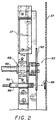
- the machine 12 has a frame 36 which includes a self-standing portion 37 having an upstream end 38 and a downstream end 40, with conversion assemblies mounted therebetween.
- the terms “upstream” and “downstream” in this context are characteristic of the direction of flow of the stock material 26 through the machine 12.
- the frame portion 37 includes four legs 41 (only two of which are visible in the illustrated orientation). Additionally, in the illustrated embodiment, "stilts" 42 are provided so that the height of the machine 12 is appropriate for the transitional zone or slide 16.
- the frame 36 further comprises an extension 43 attached to the downstream end 40 of the self-standing frame portion 37.
- the extension 43 includes a horizontal shelf 44, and a casing 46 which, together with the shelf 44, forms a rectangular tunnel 47.
- the conversion assemblies include a stock supply assembly 50, a forming assembly 52, a gear assembly 54, and a cutting assembly 56, all of which are mounted to the frame 36, and the pad-transferring assembly 24 mounted to the frame extension 43.
- the stock supply assembly 50 is mounted to the upstream end 38 of the self-standing frame portion 37 of the frame 36;
- the forming assembly 52 is mounted on the frame portion 37 downstream of the stock supply assembly 50;
- the gear assembly 54 is mounted on the frame portion 37 downstream of the forming assembly 52.
- the cutting assembly 56 is mounted on both the self-standing frame portion 37 and the frame extension 43, with its “cutting element" ( i . e , its blade 57 which may be seen by referring briefly to Figure 9) being positioned within the tunnel 47.
- the pad-transferring assembly 24 is mounted to the frame extension 43 with a portion of the pad-transferring assembly positioned within the tunnel 47, just downstream of the cutting assembly 56 in order to engage the pad 14.
- the stock supply assembly 50 supplies the stock material 26 to the forming assembly 52.
- the forming assembly 52 causes inward rolling of the lateral edges of the sheet-like stock material to form the lateral pillow-like portions of the continuous strip 29.
- the gear assembly 54 pulls the stock material downstream through the machine and also coins the central band of the continuous strip to form the coined strip 30.
- the cutting assembly 56 cuts the strip into pads 14 of a desired length.
- the pad-transferring assembly 24 frictionally engages the leading portion of the coined strip prior to it being cut and then frictionally transfers the pad 14 (formed when the coined strip 30 is cut) to the slide 16.
- gear assembly 54 it includes a drive gear 60 and a loosely meshed idler gear 62.
- the drive gear 60 is fixedly mounted to a shaft 66 which is rotatably mounted to the frame 36 by bearing structures 68.
- bearing structures 68 See Figures 2 and 3.
- a sprocket at one end of the shaft 66 accommodates a chain which connects the shaft to a motor 70.
- the gear motor 70 rotates the drive shaft 66 (and thus the drive gear 60) in an appropriate direction whereby the central band of the strip is grabbed by the gear teeth and pulled downstream through the nips of the gears 60 and 62. (This "grabbing" simultaneously coins the layers of the central band together to form the coined strip 30.)
- the gear assembly 54 is a rotating conversion assembly and its angular movement directly corresponds to the length of the coined strip 30 and therefore the cushioning products, or pads, 14.
- one revolution of the drive gear 60 produces a coined strip which is approximately twelve inches, or one foot long. In other words, every 30° increment of angular movement by the drive gear 60 corresponds to one inch of the coined strip, or pad.
- the length measuring device 22 is positioned to monitor the angular movement of the gear assembly 54.
- angular motion data is sent to the process controller 20 to produce pads of appropriate lengths.
- the bar code on the box 18 may indicate to the scanner 25 that the box requires three pads: a three foot pad, a one foot pad, and a six inch pad.
- the process controller 20 would activate the gear assembly 54 ( i . e ., send an activation signal to the motor 70), and monitor the angular motion of the drive gear 60. Since the length measuring device 24 determines length measurements based on the actual angular movement of the drive gear 60, gear velocity (and the inaccuracies associated therewith) become irrelevant in length determinations.
- the process controller 20 When the angular motion of the gear assembly 54 corresponded to three feet of cushioning product (three revolutions in the preferred embodiment), the process controller 20 would deactivate the gear assembly 54 ( i . e ., send a deactivation signal to the motor 70) and the cutter assembly 56 would be activated to cut the coined strip. This process would be repeated for the next two pads, except that the process controller 20 would deactivate the gear assembly 54 when its angular movement corresponded to a one foot pad length and a half-a-foot pad length, respectively (a full revolution and a half a revolution, respectively, in the preferred embodiment).
- the length measuring device 22 includes a rotating member 80 which is attached to the gear shaft 66 and a monitor 82 which monitors the angular motion of the member 80, and thus the gear shaft 66.
- the rotating member 80 is a disk with a series of openings 84 arranged in equal circumferential increments. More preferably, the rotating member 80 is a black, nonreflective, aluminum disk with twelve openings. In this manner, each opening 84 will correspond to a 30° angular movement and, in the preferred embodiment, one inch of pad length.
- the monitor 82 comprises a photo-optic transmitter/ receiver 86 which transmits and receives light beams and a reflector 88 which reflects the transmitted light beams.
- the transmitter/receiver 86 is mounted on the machine frame portion 37 and is positioned so that, as the rotating member 80 turns, transmitted light beams will travel through the openings 84.
- a suitable photo-optic transmitter/receiver 86 is manufactured by Banner under the catalog number SM2A312LV. It may be noted for future reference that the photo-optic transmitter/receiver 86 includes electrical circuitry capable of relaying interruptions in the receipt of light beams.
- the reflector 88 is likewise mounted on the frame portion 37, but is positioned to receive transmitted light beams which travel through the openings 84.
- a suitable reflector is manufactured by Opcon under catalog number 6202AXXXX.
- the transmitter/receiver 86 relays the occurrence of an interruption to the process controller 11 in the form of a pulse.
- the process controller 20 uses this information to control the gear assembly 56 ( i . e ., to send activation/deactivation signals to the motor 70) and thus uses this information to control pad lengths. For example, if the bar code on the box 18 indicated that a three foot pad was necessary, the process controller 20 would deactivate the preferred gear assembly 54 after thirty-six pulses were relayed. Likewise if a six inch pad was necessary, the process controller 20 would deactivate the preferred gear assembly 54 after six pulses were relayed.
- the pad-transferring assembly 24 which transfers the pads after being formed in the appropriate lengths, is best shown in schematic illustrations 4A-4C.
- the pad-transferring assembly is designed to frictionally engage (or “grab") the leading end of the coined strip 30 prior to it being cut.
- the pad-transferring assembly 24 continues to frictionally engage the leading edge of the coined strip 30.
- the pad-transferring assembly 24 immediately transfers the cut pad 14 towards the transitional zone or slide 16, or, in other words, away from the cutting assembly 56.
- it is the upper surface of the strip 30 and the upper surface of the cut pad 14 which are frictionally engaged during the transferring process.
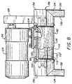
- the pad-transferring assembly 24 is illustrated isolated from the other assemblies of the machine 12. As shown, the pad-transferring assembly 24 comprises a support structure 90, a conveyor 92, a drive unit 94, a guide chute 96, and a series of coupling elements 98 a - 98 l .
- the support structure 90 includes a top plate 100, two side plates 102, two guard plates 104, a motor-mounting plate 106, and a back-up plate 108.
- the top plate 100 is sized/shaped to cover the upper surface of the conveyor 92.
- the side plates 102 which are attached to the lateral edges of the top plate 100 by capscrews 98a, are sized/shaped to cover the lateral surfaces of the conveyor 92. It may be noted for future reference that each side plate 102 includes an open elongated slot 109. (See Figure 6.)
- the guard plates 104 are attached to the upstream/downstream edges of the top plate 100 by capscrews 98 b and they are sized/shaped to shield the space between the top plate 100 and the conveyor 92.
- the motor-mounting plate 106 is attached to the upper surface of the top plate 100 by capscrews 98 c and, as the name implies, it is sized/shaped to mount a motor.
- the back-up plate 108 is attached to the lower edges of the side plates 102 by capscrews 98 d . (See Figures 6 and 7.) For ease in explanation, the description of the size, shape and purpose of the back-up plate 108 is presented below in connection with the conveyor 92.
- the conveyor 92 includes a drive roller 110 non-rotatably mounted on a drive shaft 111 by setscrews 98 e , an idler roller 112 rotatably mounted on an idler shaft 113 by bearings 98 f , a take-up roller 114 rotatably mounted on a take-up shaft 115 by bearings 98 g , and an endless belt 116 wrapped around the rollers 110, 112, and 114.
- the drive shaft 111 is rotatably mounted to the side plates 102 by bearings 98 h and the idler shaft 113 is non-rotatably mounted to the side plates 102 by setscrews 98 i .
- both ends of the take-up shaft 115 extend outwardly from the side plates 102 through the elongated slots 109 and the shaft 115 non-rotatably held this position, as is explained in more detail below. It may be noted for future reference that one end of the drive shaft 111 extends outwardly from a side plate 102. (See Figure 5.)
- the back-up support plate 108 it is positioned between the drive roller 110 and the idler roller 112, and just above the belt 116. (See Figure 6.) Accordingly, it is sized/shaped for this positioning.
- the back-up plate 108 provides an upper support surface for the endless belt 116.
- the conveyor 92 may additionally comprise an adjustment mechanism 118 for selectively adjusting the tension and/or the longitudinal orientation of the belt 116.
- the mechanism 110 along with the belt 116, function to nonrotatably mount the take-up shaft 115 to the side plates 102.
- the adjusting elements of the mechanism 118 are a pair of threaded rods 120 which interact with the flattened ends of the take-up shaft 115 to adjust their point of insertion through the slots 109.
- the rods 120 extend through threaded bores in blocks 122 which are coupled to the side plates 102 by capscrews 98 j .
- the threaded arrangement between the rods 120 and the blocks 122 allows controlled and concise adjustments by "screwing/unscrewing" the rods 120. (See Figures 5 and 6.)
- the drive unit 94 includes a motor 124, which is mounted to the motor mounting plate 106 by capscrews 98 k and thus is mounted to the top support plate 100.
- the drive unit 94 also includes components for transferring the rotational power of the motor 124 to the conveyor 92. More specifically, these components transfer rotational motion to the drive roller 110 which in turn rotates the conveyor belt 116, and thus, the idler roller 112 and the take-up roller in the appropriate direction.
- the illustrated transfer components comprise a pulley 126 which is attached to the motor shaft, a pulley 127 which is attached to one end of the drive shaft 111 (i.e, the end which extends through the side plate 102), and a belt 128 wrapped around the pulleys 126 and 127.
- the drive unit 94 may additionally include a belt guard 129 to shield the motor belt 128 from external interferences.
- the guide chute 96 comprises two tracks 130 (See Figures 5, 7 and 8) symmetrically positioned to form a bottomless channel below the conveyor 92 for the cut pads 14 to travel through during the transferring process.
- the tracks 130 each include a downstream section 132 and an upstream section 134, both sections having an "upside-down L" cross sectional geometry.
- Each track's downstream section 132 has uniform cross section geometry and each track's upstream section 134 is flared (both outwardly and upwardly) towards its upstream edge. (See Figures 7 and 8.) In this manner, the bottomless channel has a relatively wide entrance for the initial insertion of the leading edge of the coined strip 30 and/or the cut pad 14.
- the guide chute 96 further comprises two vertical flanges 136, one for each track 130, which project from the top upstream edge of the track 130.
- the inner edges of the flanges 136 are coupled to the upstream edges of the side plates 102 by capscrews 98 l to thereby couple the guide chute 96 to the support structure 90. (See Figures 5 and 8.)
- the pad-transferring assembly 24 is shown mounted to the machine frame 36 or, more particularly, the tunnel-forming components 44 and 46 of the frame extension 37.
- This mounting is accomplished by a mounting plate 140, a top mounting bracket 142, a pair of bottom mounting brackets 144, and a series of coupling elements 146 a -146 h .
- the mounting plate 140 is coupled to the machine frame 36
- the top and bottom brackets 142 and 144 are coupled to mounting plate 140
- the top bracket 142 is coupled to the pad-transferring assembly 24.
- the top and bottom brackets 142 and 144 are also coupled to each other and are arranged so that the bottom brackets 144 can function as a braces for the top bracket 142.
- the one-piece mounting plate 140 includes a horizontal mounting surface 150, a top vertical flange 152, and a pair of bottom vertical flanges 154. As is best seen in Figure 11, the mounting surface 150 is located on an inside surface of the end wall of the casing 46. The geometry of the mounting surface 150 is chosen to accommodate the coupling of the brackets 142 and 144 thereto and also to reinforce the casing 46, particularly its end wall. To this end, the mounting surface 150 includes a laterally-extending section 156 and two vertically-extending sections 158.
- the laterally-extending section 156 extends downward from the top vertical flange 152.
- the two vertically-extending sections 158 extend between intermediate regions of the laterally-extending section 156 and the bottom vertical flanges 154. Specifically, the vertically-extending sections 158 are positioned adjacent the lateral edges of the casing's outlet opening. (See Figure 11.) As is best seen in Figure 10, the sections 156 and 158 may be coupled to the casing 46 by capscrews 146 a and 146 b , respectively.
- the top vertical flange 152 is attached to the upper wall of the casing 46 by capscrews 146 c .
- the bottom vertical flanges 154 project outwardly from the tunnel 47 and are attached to the upper surface of the shelf 44 by capscrews 146 d . (See Figure .)
- capscrews 146 a - 146 d couple the mounting plate 140 to the machine frame 36.
- the top mounting bracket 142 has a "backwards L" sectional geometry and each of the bottom brackets 144 has an "upside-down L" sectional geometry.
- the top mounting bracket 142 which spans the distance between the two vertically-extending sections 158, is coupled to the laterally-extending section 156 (and also the casing 46) by capscrews 146e extending through the vertical leg of the bracket 142.
- the bottom brackets 144 are of substantially the same width as the vertically-extending sections 158 and they are coupled thereto (and also the casing 46) by capscrews 146 f extending through the bracket's horizontal legs. In this manner, the top and bottom brackets 142 and 144 are coupled to the mounting plate 140, and, consequently, to the machine frame 36.
- vertically elongated slots are used in conjunction with the capscrews 146 e and 146 f for selective up/down adjustments of the brackets 142 and 144 (and thus the pad-transferring assembly 24) relative to the mounting plate 140 (and thus the tunnel 47 or the machine frame 36).
- the top mounting bracket 142 is coupled to the top support plate 100 by capscrews 146 e which extend through the bracket's horizontal leg. (Thus, the pad-transferring assembly 24 is hung in a cantilever fashion from the frame extension 43.) In this manner, the pad-transferring assembly 24 is coupled to the top mounting bracket 142 whereby it is coupled to the mounting plate 140 and therefore the machine frame 36.
- top and bottom brackets 142 and 144 are coupled to each other and are arranged so that the bottom mounting brackets 144 can function as a braces for the top mounting bracket 142.
- the brackets 142 and 144 are coupled to each other by capscrews 146 f extending through their horizontal legs. (See Figure 10.) As is best seen in Figure 9, this arrangement allows the bottom brackets 144 to share the load of the cantilevered pad-transferring assembly 24.
- the cushioning conversion machine 12 may further include a transitional ledge 160.
- the transition ledge 160 has an "upside-down L" cross sectional geometry, with its vertical leg being attached to the downstream edge of the shelf 44 by a capscrew 162. This attachment is accomplished so that the ledge's horizontal leg is flush with the upper surface of the shelf 44 and projects outwardly therefrom. In this manner, the transitional ledge 160 forms a smooth transition surface between the shelf 44 and the pad-transfer assembly 24. (See Figure 9.)
- the slide 16 provides a transitional zone which can accommodate pads 14 of substantial lengths, which presents the pads in an orderly sequential fashion, which occupies a minimal amount of space, and which maximizes packaging efficiency.
- the slide 16 includes a smooth sloped surface 170 positioned proximate to the exit of the machine 12 so that the discharged cushioning pads 14 will be deposited thereon. (See Figures 1 and 12.)
- the sloped surface 170 has a pitch angle ⁇ (see Figure 13) which is sufficient to ensure that cushioning pads 14 deposited on its top portion will slide in a predetermined slide direction S (see Figure 1).
- the pitch angle ⁇ is preferably between 25° and 35°, and, more preferably approximately 30°.
- the smooth sloped surface 170 is oriented relative to the machine 12 in such a manner that the slide direction S is substantially perpendicular to the discharge direction D . (See Figure 1.) Additionally, the plane of the smooth sloped surface 170 is substantially parallel to the discharge direction D . This geometric relationship allows the cushioning products 14 to stack in a consecutive side-by-side arrangement and thereby present the pads in an orderly sequential fashion.
- the slide 16 includes a tray 174, which incorporates the smooth sloped surface 170, and a support structure 176, which supports the tray 174 (and thus the smooth sloped surface 170) in the proper orientation.
- the tray 174 includes a bottom wall 178 and a set of side walls 180 which surround the bottom wall 178 and which extend perpendicularly upward therefrom. The upper surface of the bottom wall 178 forms the smooth sloped surface 170.
- the tray 174 is preferably of a one-piece fabrication and is preferably made of stainless steel. More preferably, the tray 174 is made of #2B finish stainless steel which is annealed, pickled, and bright cold rolled. This material selection is based on the desire to optimize the "smoothness" of the sloped surface 174 so that the pads 14 will slide frictionlessly down it.
- the tray 174 is preferably left unpainted to further this objective.
- the bottom wall 178 (and thus the transitional surface 170) has a length L of approximately four feet and a width W of approximately three feet.
- the transitional zone can accommodate pads of substantial lengths ( i . e ., approximately four feet).
- the side walls 180 form a two to three inch border around the bottom wall 178 (and thus the transitional surface 170) so that the stacked pads 14 will be retained therein.
- the upper edges of the side walls 180 are rolled, and their comers seams are welded, so that tray 174 will be free of any burs or projections which could cause interference during the packaging process.
- the support structure 176 supports the tray 174, and therefore the smooth sloped surface 170, in the proper orientation.
- the height H B of the bottom edge of the tray 174 is approximately thirty-six inches and the height H U of the tray's upper edge is approximately fifty-four inches. This positions the bottom (or front) edge of the tray 174 at the waist level of most packaging personnel. In this manner, a packaging person can easily retrieve the cushioning products 14 from the transitional zone ( i . e ., he/she does not have to bend over) thereby maximizing packaging efficiency.
- the support structure 176 comprises a pair of front leg members 190, a pair of back leg members 192, a back brace member 194, and four side brace members 196.
- the particular design of the support structure 176 allows the slide 16 to occupy a minimal amount of space at the packaging site. Specifically, the slide 16 will occupy approximately 101 ⁇ 2 square feet of floor space.
- the support members 190, 192, 194, and 196 are all preferably made of steel and, more preferably, are all made of 11 gauge, 11 ⁇ 2 inch square, tubular steel and painted to prevent rust.
- the front leg members 190 are attached ( e . g ., bolted) to the front corners of the tray 174 and the back leg members 192 are attached ( e . g ., bolted) to the back comers of the tray 174.
- the front leg members 190 are approximately 361 ⁇ 2 inches long and the back leg members are approximately 521 ⁇ 2 inches long.
- the preferred leg members 190/192 include bottom mounting plates 198 which may be used for permanent installation of the slide 16 at the packaging site.
- the back brace member 194 is "criss-cross" component which extends between the back leg members 192. (See Figure 12.)
- a mounting plate 200 is attached ( e . g ., welded) to each of the four distal ends of the back brace member 194.
- the mounting plates 200 are attached ( e . g ., bolted) to the back leg members 192.
- the side brace members 196 are linear components which extend between aligned front/back leg members 190/192. Specifically, in the preferred embodiment, two brace members 196 are horizontally arranged on each lateral set of front/back members 190/192. (See Figure 13.) The ends of the side brace members 196 are preferably directly attached ( e . g ., welded) to the leg members 190/192.
- the slide 16 disassembles into four substantially planar pieces: the tray 174, the back brace member 194, and the two sides of the support structure ( i . e ., a front leg member 190, a back leg member 192, and two side brace members 196 coupling them together).
- the present invention provides a length measuring device, a pad-traruferring assembly and a transitional slide which may be used individually or together in conjunction with a sophisticated packaging program controlled by a process controller.
Abstract
Claims (14)
- Système d'emballage (10) comportant une machine (12) de conversion pour rembourrage ayant un châssis (36) et des ensembles de conversion qui sont montés sur le châssis et qui convertissent une matière de stock (26) en un produit de rembourrage, le système étant caractérisé en ce qu'il comporte
un dispositif (20) de commande de processus destiné à déterminer automatiquement une longueur souhaitée d'un produit de rembourrage pour une caisse (18) puis à commander automatiquement la machine de conversion pour rembourrage afin de produire ledit produit de rembourrage de la longueur appropriée ;
un dispositif (22) de mesure de longueur qui mesure la longueur du produit de rembourrage en même temps qu'il est produit, le dispositif de mesure de longueur comprenant un circuit électrique destiné à relayer une information de longueur au dispositif de commande de processus pour commander la machine afin de produire le produit de rembourrage ; et
un capteur (25) destiné à capter les exigences de rembourrage d'une caisse, le capteur étant relié au dispositif de commande de processus pour fournir une information d'exigences de rembourrage au dispositif de commande de processus. - Système d'emballage selon la revendication 1, caractérisé en ce que les ensembles de conversion comprennent un ensemble de conversion tournant ; et en ce que le dispositif (22) de mesure de longueur comprend :un élément rotatif (80) qui est relié à l'ensemble rotatif de conversion et qui tourne avec lui ; etun élément de contrôle (82) qui contrôle le mouvement angulaire de l'élément rotatif et, par conséquent, de l'ensemble rotatif de conversion.
- Système d'emballage selon la revendication 2, caractérisé en ce que l'élément rotatif (80) comporte un disque présentant une série d'ouvertures (84) agencées à des pas circonférentiels égaux.
- Système d'emballage selon la revendication 2 ou 3, caractérisé en ce que l'élément de contrôle comporte un émetteur/récepteur photo-optique (86) qui émet et reçoit des faisceaux lumineux et un réflecteur (88) qui réfléchit les faisceaux lumineux ;
l'émetteur/récepteur photo-optique étant positionné de manière que, lorsque l'élément rotatif tourne, des faisceaux lumineux émis passent à travers ses ouvertures (84) ;
le réflecteur étant positionné de façon à recevoir les faisceaux lumineux émis qui passent à travers les ouvertures et à renvoyer par réflexion, à travers les ouvertures, ces faisceaux lumineux émis. - Système d'emballage selon l'une quelconque des revendications 2 à 4, caractérisé en ce que les ensembles de conversion comprennent :un ensemble de formage (52) qui roule, vers l'intérieur, les bords latéraux de la matière de stock (26) analogue à une feuille pour former un ruban continu ayant des parties latérales analogues à des coussins et une bande centrale mince ;un ensemble (50) d'alimentation en matière de stock qui fournit la matière de stock analogue à une feuille à l'ensemble de formage ;un ensemble à engrenage (54) qui tire la matière de stock à travers l'ensemble de formage et qui estampe la bande centrale du ruban continu pour former une bande estampée, l'ensemble à engrenage étant l'ensemble rotatif de conversion ; etun ensemble de coupe (56) qui coupe le ruban estampé en matelas (14) d'une longueur souhaitée.
- Système d'emballage selon l'une quelconque des revendication précédentes, caractérisé par un ensemble de coupe (56) monté sur le châssis en aval des ensembles de conversion, qui coupe le produit de rembourrage en un matelas (14) d'une longueur souhaitée ; et
un ensemble (24) de transfert de matelas monté sur le châssis (36) en aval de l'ensemble de coupe, qui transfère le matelas coupé à l'écart de l'ensemble de coupe. - Système d'emballage selon l'une quelconque des revendications précédentes, caractérisé en ce que le châssis (36) de la machine comprend une sortie à travers laquelle les produits de rembourrage sont déchargés dans une direction prédéterminée de déchargement ; et comprenant un coulisseau (16) ayant une surface en pente douce avec une partie supérieure positionnée à proximité de la sortie de la machine afin que le produit de rembourrage déchargé soit déposé sur elle ; la surface en pente douce ayant un angle d'inclinaison qui est suffisant pour assurer que les produits de rembourrage placés sur la partie supérieure de la surface glissent dans une direction prédéterminée de glissement ; et la surface en pente douce étant orientée par rapport à la machine d'une manière telle que la direction de glissement est sensiblement perpendiculaire à la direction de déchargement.
- Procédé d'emballage, comprenant la mise en oeuvre d'une machine (12) de conversion pour rembourrage ayant un châssis (36), et des ensembles de conversion qui sont montés sur le châssis et qui convertissent une matière de stock (26) en un produit de rembourrage, caractérisé en ce que le procédé comprend :la mise en oeuvre d'un dispositif de commande de processus relié fonctionnellement à la machine de conversion pour rembourrage, pour déterminer automatiquement une longueur souhaitée du produit de rembourrage pour une caisse (18) ;la commande automatique de la machine de conversion pour rembourrage afin de produire le produit de rembourrage de la longueur appropriée ;l'utilisation d'un dispositif de mesure de longueur pour mesurer la longueur du produit de rembourrage en même temps qu'il est produit, l'étape de mesure de la longueur comprenant la sous-étape consistant à relayer par un circuit électrique une information de longueur au dispositif de commande de processus, afin de commander la machine pour produire le produit de rembourrage ; etl'utilisation d'un capteur (25) destiné à capter les exigences de rembourrage d'une caisse, le capteur étant relié au dispositif de commande de processus pour fournir une information portant sur les exigences de rembourrage au dispositif de commande de processus.
- Procédé selon la revendication 8, caractérisé par le contrôle du mouvement angulaire d'un élément rotatif (80) qui est relié à un ensemble rotatif de conversion faisant partie des ensembles de conversion et qui tourne avec lui.
- Procédé selon la revendication 8 ou la revendication 9, caractérisé en ce que l'étape de contrôle comprend le contrôle d'un élément rotatif (80) comportant un disque présentant une série d'ouvertures (84) agencées à des pas circonférentiels égaux.
- Procédé suivant l'une quelconque des revendication 8 à 10, caractérisé en ce que l'étape de contrôle comprend la transmission de faisceaux lumineux depuis un émetteur/récepteur photo-optique (86), lesquels faisceaux passent à travers des ouvertures (84) dans l'élément rotatif (80) pendant qu'il tourne, et sont renvoyés par réflexion, à travers les ouvertures, du réflecteur (88) à l'émetteur/récepteur photo-optique.
- Procédé selon l'une quelconque des revendications 8 à 11, caractérisé par la coupe du produit de rembourrage en un matelas (14) d'une longueur souhaitée et le transfert du matelas coupé à l'écart de l'ensemble de coupe (56).
- Procédé selon l'une quelconque des revendications 8 à 12, caractérisé par le déchargement de produit à travers une sortie dans le châssis, dans une direction prédéterminée de déchargement, pour déposer les produits de rembourrage déchargés.
- Procédé selon l'une quelconque des revendications 8 à 13, caractérisé par l'utilisation d'une matière de stock (26) analogue à une feuille.
Applications Claiming Priority (7)
| Application Number | Priority Date | Filing Date | Title |
|---|---|---|---|
| US155115 | 1993-11-19 | ||
| US08/155,115 US5542232A (en) | 1993-11-19 | 1993-11-19 | Transitional slide for use with a cushion-creating machine |
| US08/154,911 US6168559B1 (en) | 1993-11-19 | 1993-11-19 | Cushioning conversion machine including a pad-transferring assembly |
| US154911 | 1993-11-19 | ||
| US155116 | 1993-11-19 | ||
| US08/155,116 US5571067A (en) | 1993-11-19 | 1993-11-19 | Cushioning conversion machine including a length measuring device |
| PCT/US1994/013380 WO1995013914A1 (fr) | 1993-11-19 | 1994-11-18 | Programme d'emballage |
Publications (3)
| Publication Number | Publication Date |
|---|---|
| EP0729407A1 EP0729407A1 (fr) | 1996-09-04 |
| EP0729407A4 EP0729407A4 (fr) | 1998-08-12 |
| EP0729407B1 true EP0729407B1 (fr) | 2004-07-07 |
Family
ID=27387654
Family Applications (1)
| Application Number | Title | Priority Date | Filing Date |
|---|---|---|---|
| EP95902626A Expired - Lifetime EP0729407B1 (fr) | 1993-11-19 | 1994-11-18 | Systeme et procede d'emballage |
Country Status (5)
| Country | Link |
|---|---|
| EP (1) | EP0729407B1 (fr) |
| JP (1) | JPH09510420A (fr) |
| AU (1) | AU1182895A (fr) |
| DE (1) | DE69433887T2 (fr) |
| WO (1) | WO1995013914A1 (fr) |
Families Citing this family (30)
| Publication number | Priority date | Publication date | Assignee | Title |
|---|---|---|---|---|
| US6524230B1 (en) | 1994-07-22 | 2003-02-25 | Ranpak Corp. | Packing material product and method and apparatus for making, monitoring and controlling the same |
| CA2195660C (fr) * | 1994-07-22 | 2008-03-11 | Joseph J. Harding | Machine de production de produits de calage pour emballages commandee par ordinateur |
| US5897478A (en) | 1994-07-22 | 1999-04-27 | Ranpak Corp. | Cushioning conversion machine and method using encoded stock material |
| US6217501B1 (en) | 1996-06-28 | 2001-04-17 | Ranpak Corp. | Cushioning conversion machine |
| WO1997002183A1 (fr) | 1995-07-05 | 1997-01-23 | Ranpak Corp. | Systeme d'emballage comprenant une machine de transformation de garniture d'emballage |
| EP0886573B1 (fr) * | 1995-06-26 | 2003-02-19 | Ranpak Corp. | Machine et procede de transformation d'un materiau de bourrage et son utilisation |
| US5749821A (en) * | 1995-07-21 | 1998-05-12 | Ranpak Corp. | Cushioning conversion system for converting paper stock into cushioning material with a staging area and a pick and place assembly |
| FR2746701B1 (fr) * | 1996-03-27 | 1998-06-12 | Naturembal Sa | Machine de fabrication de matelas de rembourrage a systeme de detection de rotation incorrecte du moteur de coupe et de mesure de longueur de matelas produit. |
| FR2743748B1 (fr) * | 1996-01-22 | 1998-03-27 | Naturembal Sa | Dispositif de mesure de longueur de bandes matelassees de rembourrage |
| AU1448897A (en) * | 1996-01-22 | 1997-08-20 | Naturembal (Societe Anonyme) | Cushioning pad production machine with a system for measuring the length of the resulting pad |
| AU1982597A (en) * | 1996-02-28 | 1997-09-16 | Ranpak Corp. | Cushioning conversion machine |
| WO1998000288A1 (fr) * | 1996-06-28 | 1998-01-08 | Ranpak Corp. | Machine a transformer des materiaux de rembourrage |
| AU3964897A (en) * | 1996-07-26 | 1998-02-20 | Ranpak Corp. | Cushioning conversion system |
| US5829231A (en) * | 1996-11-14 | 1998-11-03 | Ranpak Corporation | Automated cushioning producing and filling system |
| US5778631A (en) * | 1997-02-07 | 1998-07-14 | Ranpak Corp. | Automated cushioning producing and dispening system |
| EP1007344A1 (fr) * | 1997-02-14 | 2000-06-14 | Ranpak Corp. | Machine de transformation de papier en produit de calage comportant un dispositif de mesure de longueur |
| CA2293647A1 (fr) * | 1997-06-11 | 1998-12-17 | Ranpak Corp. | Systeme et procede de transformation pour materiau de rembourrage |
| ATE283165T1 (de) | 1997-09-18 | 2004-12-15 | Ranpak Corp | System und verfahren zum herstellen und ausgeben von polsterelementen |
| EP1019245B1 (fr) * | 1997-10-02 | 2004-12-15 | Ranpak Corp. | Systeme et procede de controle de machines pour la production de materiau d'emballage |
| FR2786124B1 (fr) * | 1998-11-20 | 2000-12-29 | Naturembal Sa | Machine a cycles de production de matelas de longueurs differentes |
| DE60111078T2 (de) | 2000-10-20 | 2006-05-11 | Ranpak Corp., Concord Township | Polsterumwandlungsmaschine mit polstermaterialtransfermechanismus |
| ATE330851T1 (de) | 2002-11-01 | 2006-07-15 | Ranpak Corp | Verpackungssystem mit messen vom polster- füllmaterial |
| US7186208B2 (en) | 2003-07-07 | 2007-03-06 | Ranpak Corp. | Cutterless dunnage converter and method |
| DE102014016874A1 (de) * | 2014-11-14 | 2016-05-19 | Sprick Gmbh Bielefelder Papier- Und Wellpappenwerke & Co. | Vorrichtung zum maschinellen Fertigen eines Füllmaterialerzeugnisses |
| DE102017109375A1 (de) | 2017-05-02 | 2018-11-08 | Storopack Hans Reichenecker Gmbh | Verfahren zum Polstern von Gegenständen in einem Behälter, sowie Vorrichtung zum Polstern von Gegenständen in einem Behälter |
| DE102017109829A1 (de) | 2017-05-08 | 2018-11-08 | Sprick Gmbh Bielefelder Papier- Und Wellpappenwerke & Co. | Vorrichtung zum Bereitstellen von Verpackungsmaterial |
| DE102017109851A1 (de) | 2017-05-08 | 2018-11-08 | Sprick Gmbh Bielefelder Papier- Und Wellpappenwerke & Co. | Vorrichtung zum Fertigen eines Polsterproduktes |
| DE102017109842A1 (de) * | 2017-05-08 | 2018-11-08 | Sprick Gmbh Bielefelder Papier- Und Wellpappenwerke & Co. | Vorrichtung und Verfahren zum Fertigen eines Polsterkissens aus einer ein- oder mehrlagigen kontinuierlichen Papierbahn |
| DE102017109867A1 (de) | 2017-05-08 | 2018-11-08 | Sprick Gmbh Bielefelder Papier- Und Wellpappenwerke & Co. | Vorrichtung zum Fertigen eines dreidimensionalen Verpackungserzeugnisses, wie eines Polsterproduktes, aus einer ein- oder mehrlagigen Papierbahn |
| DE102022114014A1 (de) | 2022-06-02 | 2023-12-07 | Storopack Hans Reichenecker Gmbh | Vorrichtung zum Umwandeln eines Ausgangsmaterials in ein Polstermaterial zum Füllen des Leervolumens in einem Behälter, sowie Verfahren zum Betreiben einer solchen Vorrichtung |
Family Cites Families (6)
| Publication number | Priority date | Publication date | Assignee | Title |
|---|---|---|---|---|
| FR1442386A (fr) * | 1965-04-27 | 1966-06-17 | Heliot Maurice Ets | Dispositif de groupage de sachets dans un container |
| US3509797A (en) * | 1967-05-22 | 1970-05-05 | Arpax Co | Mechanism for producing cushioning dunnage |
| DE2258546C2 (de) * | 1972-11-29 | 1982-10-21 | Siemens AG, 1000 Berlin und 8000 München | Einrichtung zur Papiervorschubüberwachung bei Druckern |
| US4557716A (en) * | 1983-07-05 | 1985-12-10 | Ranpak Corp. | Mechanism for producing pad-like cushioning dunnage from sheet material |
| DD274188A1 (de) * | 1988-07-25 | 1989-12-13 | Bauelemente Faserbaustoffe Veb | Vorrichtung zum ablaengen von bandfoermigen material |
| US5123889A (en) * | 1990-10-05 | 1992-06-23 | Ranpak Corporation | Downsized cushioning dunnage conversion machine and cutting assemblies for use on such a machine |
-
1994
- 1994-11-18 DE DE69433887T patent/DE69433887T2/de not_active Expired - Lifetime
- 1994-11-18 AU AU11828/95A patent/AU1182895A/en not_active Abandoned
- 1994-11-18 EP EP95902626A patent/EP0729407B1/fr not_active Expired - Lifetime
- 1994-11-18 JP JP7514642A patent/JPH09510420A/ja active Pending
- 1994-11-18 WO PCT/US1994/013380 patent/WO1995013914A1/fr active IP Right Grant
Also Published As
| Publication number | Publication date |
|---|---|
| DE69433887D1 (de) | 2004-08-12 |
| WO1995013914A1 (fr) | 1995-05-26 |
| DE69433887T2 (de) | 2005-07-14 |
| AU1182895A (en) | 1995-06-06 |
| JPH09510420A (ja) | 1997-10-21 |
| EP0729407A1 (fr) | 1996-09-04 |
| EP0729407A4 (fr) | 1998-08-12 |
Similar Documents
| Publication | Publication Date | Title |
|---|---|---|
| EP0729407B1 (fr) | Systeme et procede d'emballage | |
| US5571067A (en) | Cushioning conversion machine including a length measuring device | |
| WO1997031773A9 (fr) | Machine de conversion de rembourrages | |
| EP0889779A2 (fr) | Machine de conversion de rembourrages | |
| EP1027214B1 (fr) | Systeme de conversion en materiau de rembourrage et procede de fabrication d'une bobine de materiau de rembourrage | |
| EP0885114B1 (fr) | Systeme de transformation pour la fabrication de produits de calage | |
| US5868657A (en) | Cushioning conversion system with accumulator conveyor | |
| US6217501B1 (en) | Cushioning conversion machine | |
| US6026632A (en) | Packaging system and method including cushioning conversion machine with sloped chute and auto-feed | |
| US6168560B1 (en) | Cushioning conversion machine and method with pad transferring device | |
| EP0921937B1 (fr) | Systeme pour transformer des materiaux de rembourrage | |
| US5542232A (en) | Transitional slide for use with a cushion-creating machine | |
| US5778631A (en) | Automated cushioning producing and dispening system | |
| WO1998004402A9 (fr) | Systeme pour transformer des materiaux de rembourrage | |
| CA2176730C (fr) | Systeme de production de materiau de rembourrage | |
| US6168559B1 (en) | Cushioning conversion machine including a pad-transferring assembly | |
| EP0910505B1 (fr) | Convertisseur pour matelassage et procede correspondant | |
| EP1323519A2 (fr) | Système de conversion en materiau de rembourrage et procédé de fabrication d'une bobine de materiau de rembourrage | |
| WO1998040204A1 (fr) | Convertisseur pour matelassage et procede correspondant | |
| WO1998035826A1 (fr) | Machine de transformation de papier en produit de calage comportant un dispositif de mesure de longueur | |
| EP1806220A2 (fr) | Système de conversion en matériau de rembourrage et procédé de fabrication d'une bobine de produit de rembourrage |
Legal Events
| Date | Code | Title | Description |
|---|---|---|---|
| PUAI | Public reference made under article 153(3) epc to a published international application that has entered the european phase |
Free format text: ORIGINAL CODE: 0009012 |
|
| 17P | Request for examination filed |
Effective date: 19960524 |
|
| AK | Designated contracting states |
Kind code of ref document: A1 Designated state(s): DE FR GB NL |
|
| RAP1 | Party data changed (applicant data changed or rights of an application transferred) |
Owner name: RANPAK CORP. |
|
| A4 | Supplementary search report drawn up and despatched | ||
| AK | Designated contracting states |
Kind code of ref document: A4 Designated state(s): DE FR GB NL |
|
| 17Q | First examination report despatched |
Effective date: 19981106 |
|
| GRAP | Despatch of communication of intention to grant a patent |
Free format text: ORIGINAL CODE: EPIDOSNIGR1 |
|
| RTI1 | Title (correction) |
Free format text: A PACKAGING SYSTEM AND A METHOD OF PACKAGING |
|
| GRAS | Grant fee paid |
Free format text: ORIGINAL CODE: EPIDOSNIGR3 |
|
| GRAA | (expected) grant |
Free format text: ORIGINAL CODE: 0009210 |
|
| AK | Designated contracting states |
Kind code of ref document: B1 Designated state(s): DE FR GB NL |
|
| REG | Reference to a national code |
Ref country code: GB Ref legal event code: FG4D |
|
| REF | Corresponds to: |
Ref document number: 69433887 Country of ref document: DE Date of ref document: 20040812 Kind code of ref document: P |
|
| ET | Fr: translation filed | ||
| PLBE | No opposition filed within time limit |
Free format text: ORIGINAL CODE: 0009261 |
|
| STAA | Information on the status of an ep patent application or granted ep patent |
Free format text: STATUS: NO OPPOSITION FILED WITHIN TIME LIMIT |
|
| 26N | No opposition filed |
Effective date: 20050408 |
|
| PGFP | Annual fee paid to national office [announced via postgrant information from national office to epo] |
Ref country code: NL Payment date: 20091112 Year of fee payment: 16 |
|
| REG | Reference to a national code |
Ref country code: NL Ref legal event code: V1 Effective date: 20110601 |
|
| PG25 | Lapsed in a contracting state [announced via postgrant information from national office to epo] |
Ref country code: NL Free format text: LAPSE BECAUSE OF NON-PAYMENT OF DUE FEES Effective date: 20110601 |
|
| PGFP | Annual fee paid to national office [announced via postgrant information from national office to epo] |
Ref country code: GB Payment date: 20131120 Year of fee payment: 20 Ref country code: DE Payment date: 20131121 Year of fee payment: 20 Ref country code: FR Payment date: 20131120 Year of fee payment: 20 |
|
| REG | Reference to a national code |
Ref country code: DE Ref legal event code: R071 Ref document number: 69433887 Country of ref document: DE |
|
| REG | Reference to a national code |
Ref country code: GB Ref legal event code: PE20 Expiry date: 20141117 |
|
| PG25 | Lapsed in a contracting state [announced via postgrant information from national office to epo] |
Ref country code: GB Free format text: LAPSE BECAUSE OF EXPIRATION OF PROTECTION Effective date: 20141117 |