EP0728958B1 - A clutch device - Google Patents
A clutch device Download PDFInfo
- Publication number
- EP0728958B1 EP0728958B1 EP96102487A EP96102487A EP0728958B1 EP 0728958 B1 EP0728958 B1 EP 0728958B1 EP 96102487 A EP96102487 A EP 96102487A EP 96102487 A EP96102487 A EP 96102487A EP 0728958 B1 EP0728958 B1 EP 0728958B1
- Authority
- EP
- European Patent Office
- Prior art keywords
- cam
- roller
- clutch
- clutch device
- elements
- Prior art date
- Legal status (The legal status is an assumption and is not a legal conclusion. Google has not performed a legal analysis and makes no representation as to the accuracy of the status listed.)
- Expired - Lifetime
Links
- 230000007246 mechanism Effects 0.000 claims description 18
- 230000005540 biological transmission Effects 0.000 description 7
- 230000009471 action Effects 0.000 description 2
- 238000005452 bending Methods 0.000 description 2
- 238000013459 approach Methods 0.000 description 1
- 230000008901 benefit Effects 0.000 description 1
- 239000000969 carrier Substances 0.000 description 1
- 230000008859 change Effects 0.000 description 1
- 230000009194 climbing Effects 0.000 description 1
- 238000006073 displacement reaction Methods 0.000 description 1
- 230000008030 elimination Effects 0.000 description 1
- 238000003379 elimination reaction Methods 0.000 description 1
- 230000000977 initiatory effect Effects 0.000 description 1
- 238000003754 machining Methods 0.000 description 1
- 238000004519 manufacturing process Methods 0.000 description 1
- 230000009467 reduction Effects 0.000 description 1
- 230000000717 retained effect Effects 0.000 description 1
Images


Classifications
-
- F—MECHANICAL ENGINEERING; LIGHTING; HEATING; WEAPONS; BLASTING
- F16—ENGINEERING ELEMENTS AND UNITS; GENERAL MEASURES FOR PRODUCING AND MAINTAINING EFFECTIVE FUNCTIONING OF MACHINES OR INSTALLATIONS; THERMAL INSULATION IN GENERAL
- F16D—COUPLINGS FOR TRANSMITTING ROTATION; CLUTCHES; BRAKES
- F16D13/00—Friction clutches
-
- F—MECHANICAL ENGINEERING; LIGHTING; HEATING; WEAPONS; BLASTING
- F16—ENGINEERING ELEMENTS AND UNITS; GENERAL MEASURES FOR PRODUCING AND MAINTAINING EFFECTIVE FUNCTIONING OF MACHINES OR INSTALLATIONS; THERMAL INSULATION IN GENERAL
- F16D—COUPLINGS FOR TRANSMITTING ROTATION; CLUTCHES; BRAKES
- F16D25/00—Fluid-actuated clutches
- F16D25/02—Fluid-actuated clutches with means for actuating or keeping engaged by a force derived at least partially from one of the shafts to be connected
Definitions
- the present invention relates to a clutch device according to the preamble of the patent claim 1.
- a cam mechanism is provided between two members rotating relatively to each other so that a force generated due to the relative rotation of the members and acting in the circumferential direction is converted to a thrust acting in the axial direction which is used as a clutch-engagement force.
- a cam roller is arranged between a pair of cam members, each having a cam surface opposing to each other, and generates an axial thrust by the enlargement of a distance between the cam surfaces caused by the climbing of the cam roller on the cam surfaces due to the relative rotation of the cam members.
- the clutch disk is pushed by this thrust.
- the respective cam surface is formed to have a slope suitable therefor, and one end of the cam surface is formed to be a limiter surface for limiting the displacement of the cam roller.
- a further state of the art according to reference US-A-2 057 742, which discloses the preamble of claim 1 is directed to a clutch structure especially to a clutch device having a pair of members disposed at a distance on a common axis and said members are relatively rotatable to each other on said common axis.
- a cam mechanism is arranged which comprises a pair of cam elements, each having a cam surface and a cam roller disposed between said cam surfaces.
- a limiter means is arranged for limiting said relative rotational movement of the cam elements when the relative rotation occurs between the members in the direction reverse to that in which the axial thrust is generated between said pair of members.
- Fig. 1 schematically illustrates an overall structure of an automatic transmission for the purpose of explaining where an embodiment of the present invention is used in the automatic transmission.
- AT generally represents an automatic transmission which basically comprises three sets of planetary gear units and plural frictional engagement devices for engaging and disengaging ring gears, sun gears, carriers composing the planetary gear units to and from each other, the details thereof being as follows:
- CG 1 and CG 2 represent a counter drive gear and a counter driven gear, respectively, which transmit the engine torque to a post-stage mechanism but have no relation to speed changing.
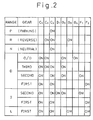
- the table shown in Fig. 2 shows a combination of the engagement and disengagement of frictional engagement elements to attain desired speeds at each range and gear speed.
- Fig. 3 illustrates a side sectional view of an automatic transmission to which a first embodiment of the present invention is built-in, wherein reference numeral 1 represents a piston; 2 represents a cam roller; and 3 represents a pressure plate.
- reference numeral 1 represents a piston
- 2 represents a cam roller
- 3 represents a pressure plate.
- cam grooves 1c and 3c are formed opposing to each other at several locations in the circumferential direction, so that a cam roller 2 is accommodated in the respective pair of opposed cam grooves.
- the cam roller 2 is rotatably retained by a roller cage 4.
- a clutch casing 100 consists of outer and inner halves welded to each other at part A to form an integral body, and coupled to the O/D planetary sun gear S 3 while being rotatable relative to a housing 200.
- the piston 1 is spline-coupled to the clutch casing 100 at part B and is movable to the right and left in the figure in an annular cylinder formed in the interior of the clutch casing 100.
- a hydraulic pressure is supplied into space C between a back surface 1b of the piston 1 and the clutch casing 100 via an oil path 101.
- Clutch disks 5 of the clutch C 3 which are spline-coupled to the O/D planetary carrier K 3 are selectively engaged frictionally with separator plates 6 of the clutch C 3 which are spline-coupled to the clutch casing 100 with the piston 1 through the pressure plate 3.
- a spring 7 is fixedly secured, at the right end thereof, to the clutch casing 100 to always bias the piston 1 to the left in the figure.
- Clutch disks 8 of the brake B 4 which are spline-coupled to the clutch casing 100 are selectively engaged frictionally with separator plates 9 of the brake B 4 which are spline-coupled to the housing 200 with a piston 10 of the brake B 4 .
- Figs. 4A to 4C are cross-sectional views of a cam section as seen parallel to the rotation axis.
- reference numerals 1, 2, 3, 4 and 5 represent the piston, cam roller, pressure plate, roller cage and clutch disk of the clutch C 3 shown in Fig. 3, respectively.
- cam groove 1c and a recess 1d which serves as the limiter according to the present invention are provided.
- a cam groove 3c and a projection 3d projected into the recess 1d of the piston 1 through an opening 4a formed in the roller cage 4 are provided.
- Fig. 4A illustrates a disengaging state wherein the pressure plate 3 and the C 3 clutch disk 5 are apart from each other.
- the C 3 clutch disk 5 splined-coupled to the O/D planetary carrier K 3 moves to the right in the figure, while the piston 1 and the pressure plate 3 are stationary.
- the C 3 clutch disk 5 is coupled to the O/D planetary carrier K 3 and the piston 1 is to the O/D planetary sun gear S 3 , the O/D planetary sun gear S 3 is integral with the O/D planetary carrier K 3 to be rotatable together according to this engagement.
- Fig. 4B illustrates, the piston 1 and the C 3 clutch disk 5 engaged to each other as described.
- the opening 4a of the roller cage 4 is formed to be sufficiently large, no interference occurs between the projection 3d of the pressure plate 3 and the roller cage 4 when the phase is switched from the state shown in Fig. 4A to that shown in Fig. 4B.
- Fig. 4B shows the driving state wherein the engine positively drives the wheels in all of the forward gear speeds except for the fourth gear speed.
- the second and first one-way clutches F 2 , F 1 are idling, respectively, to nullify the engine brake.
- the fourth brake B 4 is actuated to interrupt the rotation of the O/D planetary sun gear S 3 . Since the O/D planetary carrier K 3 is coupled to the O/D planetary ring gear R 3 , the rotational speed of the O/D planetary carrier K 3 temporarily becomes slower.
- the pressure plate 3 engaged with the C 3 clutch disk 5 escapes from the roller 2 in the lefthand direction in the figure, while maintaining the inner surface 1a of the piston 1 apart from the inner surface 3a of the pressure plate 3. Also the piston 1 escapes from the roller 2 in the righthand direction.
- a wall surface 1e of the recess 1d of the piston 1 approaches a wall surface 3e of the projection 3d of the pressure plate 3.
- the recess 1d of the piston 1 and the projection 3d of the pressure plate 3 are designed to abut each other before an edge 1f of the inner surface 1a of the piston 1 and an edge 3f of the cam groove 3c come into contact with the roller 2, respectively. Therefore, as shown in Fig. 4C, the roller 2 is prevented from riding on the edge 1f of the inner surface 1a of the piston 1 and the edge 3f of the cam groove 3c of the pressure plate 3 whereby the wall surface 1e of the recess 1d of the piston 1 and the wall surface 3e of the projection 3d of the pressure plate 3 abut onto each other to inhibit the further relative movement between the piston 1 and the pressure plate 3.
- a location defines a point of action on which a force is applied for limiting the relative movement between the piston 1 and the pressure plate 3.
- the shift from the fourth gear speed to the third gear speed corresponds to the change from the state shown in Fig. 4A to that shown in Fig. 4B. This is done by releasing the fourth brake B 4 and simultaneously therewith initiating the supply of hydraulic pressure to the back surface 1b of the piston 1.
- the generation of undesirable thrust can be reliably avoided when the switching operation is carried out from a state wherein the relative rotation is caused by the operation of the cam mechanism and that wherein the relative rotation is caused without the intervention of the cam mechanism.
- the second embodiment shown in Figs. 5A to 5C is substantially identical to the first embodiment except that a recess 3g is provided in the pressure plate 3 and a projection 1g is provided in the piston 1. A description of the operation is not given because it is the same as the first embodiment.
- the third embodiment shown in Figs. 6A to 6C is substantially identical to the first embodiment except that recesses 1h, 3h are provided in the piston 1 and the pressure plate 3, respectively, and a projection li, 3i are also provided in the piston 1 and the pressure plate 3. A description of the operation is not given because it is the same as the first embodiment.
- the third embodiment has an advantage in that, since the depth of the respective recess can be smaller, the thickness of the recess-carrying member can be reduced.
- Figs. 7A to 7E show the fourth embodiment wherein Fig. 7D illustrates the relationship between the roller 2 and the piston 1 as seen from the pressure plate 3, and Fig. 7E illustrates the relationship between the roller 2 and the piston 1 as seen from the piston 1.
- the roller 2 is not uniform in diameter in the widthwise direction but is divided into a central larger diameter section 2a and a smaller diameter section 2b at each end.
- a narrow cam surface 1a' wherein recesses 1k and projections 1m are provided in the side portions of the piston 1
- a narrow cam surface 3a' wherein recesses 3k and projections 3m are provided in the side portions of the pressure plate 3, whereby the larger diameter section 2a can be solely in contact with the cam surface.
- the projections 1m, 3m are designed to be higher than the center of the roller 2 so that the smaller diameter sections 2b of the roller 2 abut onto the projection 1m on the piston 1 and the projection 3m on the pressure plate 3 to inhibit the piston 1 and the pressure plate 3 from moving to the left and right in the figure and to prevent the roller 2 from riding on the cam.
- a recess 1m similar to that of the first embodiment is provided at a location further to the left from the cam surface la of the piston 1 and a projection 1p similar to that of the second embodiment is provided at a location further to the right from the cam surface 1a of the piston 1.
- a recess 3n similar to that of the first embodiment is provided at a location further to the right from the cam surface 3a of the pressure plate 3 and a projection 3p similar to that of the second embodiment is provided at a location further to the left from the cam surface 3a of the pressure plate 3.
- the piston 1 and the pressure plate 3 solely have recesses 1r, 3r, respectively, and a pair of fingers 4c are provided on the roller cage 4 by bending upright parts thereof.
- this embodiment is advantageous, compared to the fifth embodiment, in that the manufacturing cost is reduced.
- the piston 1 and the pressure plate 3 have recesses 1t, 3t, respectively, contiguous to the cam surfaces, while the roller cage 4 has a pair of fingers 4d formed by bending the roller cage upright at locations adjacent to the roller 2.
- this embodiment can be easily manufactured. Also, since elements are more collectively located in the vicinity of the roller 2 in comparison with the sixth embodiment, it is possible to dispose the device in a narrower space.
- the piston 1 and the pressure plate 3 have recesses 1v, 3v, respectively, at locations further to the right from the roller.
- the roller cage 4 has a pair of fingers 4e provided at a single location while being projected toward the piston 1 and the pressure plate 3, respectively, which are capable of abutting to the inner side walls 1w, 3w of the recesses 1v, 3v, respectively, when the relative rotation occurs in the direction wherein the cam mechanism is inoperative.
- this embodiment is advantageous in that the machining of the roller cage 4 becomes easier, in comparison with the seventh embodiment.
Landscapes
- Engineering & Computer Science (AREA)
- General Engineering & Computer Science (AREA)
- Mechanical Engineering (AREA)
- Mechanical Operated Clutches (AREA)
- Hydraulic Clutches, Magnetic Clutches, Fluid Clutches, And Fluid Joints (AREA)
- Transmission Devices (AREA)
Description
- The present invention relates to a clutch device according to the preamble of the
patent claim 1. - In clutch devices disclosed in Japanese Patent Application Nos. 6-48806 and 6-69632 (corresponding to Unexamined Patent Publication (Kokai) Nos. 7-259885 and 7-279992), a cam mechanism is provided between two members rotating relatively to each other so that a force generated due to the relative rotation of the members and acting in the circumferential direction is converted to a thrust acting in the axial direction which is used as a clutch-engagement force.
- According to the above clutch devices, it is possible to miniaturize the clutch device as a whole by a reduction in the number of clutch disks due to the utilization of a booster function and a mono-directional action of the cam mechanism and by the elimination of a one-way clutch.
- In the above clutch devices, a cam roller is arranged between a pair of cam members, each having a cam surface opposing to each other, and generates an axial thrust by the enlargement of a distance between the cam surfaces caused by the climbing of the cam roller on the cam surfaces due to the relative rotation of the cam members. Thus, the clutch disk is pushed by this thrust.
- If the cam mechanism is adapted to be operable only when the cam members rotate in one predetermined direction, the respective cam surface is formed to have a slope suitable therefor, and one end of the cam surface is formed to be a limiter surface for limiting the displacement of the cam roller.
- However, in the above devices even though the limiter surface is formed at one end of the cam surface as described above, there is a problem when the phase is switched, due to the reverse of the direction of the relative rotation, from the engaging state wherein the cam mechanism is operative to the releasing state wherein it is inoperative, in that the cam roller may ride on the edge of the limiter surface and results in a drag loss.
- A further state of the art according to reference US-A-2 057 742, which discloses the preamble of
claim 1 is directed to a clutch structure especially to a clutch device having a pair of members disposed at a distance on a common axis and said members are relatively rotatable to each other on said common axis. Between both members a cam mechanism is arranged which comprises a pair of cam elements, each having a cam surface and a cam roller disposed between said cam surfaces. Furthermore, a limiter means is arranged for limiting said relative rotational movement of the cam elements when the relative rotation occurs between the members in the direction reverse to that in which the axial thrust is generated between said pair of members. In this document it is stated that in a end relativ position of the cam members the rollers have been urged to the low points of their respective cam surfaces and against abutments formed between adjacent cam surfaces on the same cam members so as to permit the cam members to assume a position of minimum combined length. - However this state of the art has the problem that if a direction of relative rotation between both cam members is reversed under the condition that the two cam memebrs are fully apart from each other, it is easy for the cam roller to ride onto the edges of the abutments which are integrated in the cam surfaces.
- In view of this state of the art it is an object of the invention to provide a clutch device having cam members the cam sufaces thereof can be protected against wear in order to prolong the sevice life of the device.
- This object is solved by a clutch device having the technical features according to the
patent claim 1. - The present invention will be described in more detail below with reference to the preferred embodiments illustrated in the attached drawings.
- In the drawings:
- Fig. 1 is a schematic view illustrating an overall structure of an automatic transmission to which the present invention is applied;
- Fig. 2 is a table for obtaining various driving speeds;
- Fig. 3 is a side sectional view of an automatic transmission to which one embodiment of the present invention is built-in;
- Fig. 4A to 4C are views for illustrating a structure and operation of the first embodiment;
- Fig. 5A to 5C are views for illustrating a structure and operation of the second embodiment;
- Fig. 6A to 6C are views for illustrating a structure and operation of the third embodiment;
- Fig. 7A to 7E are views for illustrating a structure and operation of the fourth embodiment;
- Fig. 8A to 8C are views for illustrating a structure and operation of the fifth embodiment;
- Fig. 9A to 9C are views for illustrating a structure and operation of the sixth embodiment;
- Fig. 10A to 10C are views for illustrating a structure and operation of the seventh embodiment; and
- Fig. 11A to 11C are views for illustrating a structure and operation of the eighth embodiment.
-
- Fig. 1 schematically illustrates an overall structure of an automatic transmission for the purpose of explaining where an embodiment of the present invention is used in the automatic transmission.
- In the figure, AT generally represents an automatic transmission which basically comprises three sets of planetary gear units and plural frictional engagement devices for engaging and disengaging ring gears, sun gears, carriers composing the planetary gear units to and from each other, the details thereof being as follows:
- X1 represents an input shaft which is connected to an output shaft (not shown) of a torque converter (not shown);
- PG1, PG2 and PG3 represent a front planetary gear unit, a rear planetary gear unit and an O/D planetary gear unit, respectively;
- R1, R2 and R3 represent a front planetary ring gear, a rear planetary ring gear and an O/D planetary ring gear, respectively;
- K1, K2 and K3 represent a front planetary carrier, a rear planetary carrier and an O/D planetary carrier, respectively;
- S12 represents a front and rear planetary sun gear common to the front and rear planetary gear units, and S3 represents an O/D planetary sun gear;
- C1 represents a first clutch for engaging/disengaging the input shaft X1 to and from the front planetary ring gear R1;
- C2 represents a second clutch for engaging and disengaging the input shaft X1 to and from the front and rear planetary sun gear S12;
- C3 represents a third clutch for engaging and disengaging the O/D planetary carrier K3 to and from the O/D planetary sun gear S3, including a one-way clutch mechanism for releasing the engagement between the O/D planetary carrier K3 and the O/D planetary sun gear S3 when a fourth brake B4 described later is operated;
- B1 represents a first brake for locking the front and rear planetary sun gear S12;
- B2 represents a second brake for locking the reverse rotation (counterclockwise rotation) of the front and rear planetary sun gear S12;
- B3 represents a third brake for locking the rear planetary carrier K2;
- B4 represents a fourth brake for locking the O/D planetary sun gear S3;
- F1 represents a first one-way clutch for locking the reverse rotation (counterclockwise rotation) of the front and rear planetary sun gear S12 when the second brake B2 is operated; and
- F2 represents a second one-way clutch for locking the reverse rotation (counterclockwise rotation) of the rear planetary carrier K2.
-
- CG1 and CG2 represent a counter drive gear and a counter driven gear, respectively, which transmit the engine torque to a post-stage mechanism but have no relation to speed changing.
- The table shown in Fig. 2 shows a combination of the engagement and disengagement of frictional engagement elements to attain desired speeds at each range and gear speed.
- Accordingly, it is necessary to engage the O/D planetary carrier K3 with the O/D planetary sun gear S3 in all forward speed ranges except for the fourth speed; to release the engagement simultaneously with the actuation of the fourth brake B4 in the up-shift from the third speed to the fourth speed; and to release the fourth brake B4 simultaneously with the above engagement in the down-shift from the fourth speed to the third speed.
- While the rotational direction of the O/D planetary carrier K3 in the reverse speed is opposite to those in the forward speeds, it is necessary, even in this case, to engage the O/D planetary carrier K3 with the O/D planetary sun gear S3.
- In the engine-brake state wherein the O/D planetary sun gear S3 is an input side, the above engagement is necessary in all the speed ranges including the reverse range, except for first and second speeds in the D-range.
- The embodiments described below are those having a function similar to that of the third clutch C3 of the automatic transmission shown in Fig. 1.
- Fig. 3 illustrates a side sectional view of an automatic transmission to which a first embodiment of the present invention is built-in, wherein
reference numeral 1 represents a piston; 2 represents a cam roller; and 3 represents a pressure plate. Oninner surfaces piston 1 and thepressure plate 3, respectively,cam grooves 1c and 3c are formed opposing to each other at several locations in the circumferential direction, so that acam roller 2 is accommodated in the respective pair of opposed cam grooves. Thecam roller 2 is rotatably retained by aroller cage 4. - A
clutch casing 100 consists of outer and inner halves welded to each other at part A to form an integral body, and coupled to the O/D planetary sun gear S3 while being rotatable relative to ahousing 200. - The
piston 1 is spline-coupled to theclutch casing 100 at part B and is movable to the right and left in the figure in an annular cylinder formed in the interior of theclutch casing 100. A hydraulic pressure is supplied into space C between aback surface 1b of thepiston 1 and theclutch casing 100 via anoil path 101. -
Clutch disks 5 of the clutch C3 which are spline-coupled to the O/D planetary carrier K3 are selectively engaged frictionally withseparator plates 6 of the clutch C3 which are spline-coupled to theclutch casing 100 with thepiston 1 through thepressure plate 3. - A
spring 7 is fixedly secured, at the right end thereof, to theclutch casing 100 to always bias thepiston 1 to the left in the figure. - Clutch disks 8 of the brake B4 which are spline-coupled to the
clutch casing 100 are selectively engaged frictionally withseparator plates 9 of the brake B4 which are spline-coupled to thehousing 200 with apiston 10 of the brake B4. - The structure and operation of the first embodiment will be described with reference to Figs. 4A to 4C which are cross-sectional views of a cam section as seen parallel to the rotation axis.
- In Fig. 4A,
reference numerals - On the
inner surface 1a of thepiston 1 a cam groove 1c and arecess 1d which serves as the limiter according to the present invention are provided. On the other hand, on theinner surface 3a of thepressure plate 3 acam groove 3c and aprojection 3d projected into therecess 1d of thepiston 1 through anopening 4a formed in theroller cage 4 are provided. - Fig. 4A illustrates a disengaging state wherein the
pressure plate 3 and the C3clutch disk 5 are apart from each other. In this state, the C3clutch disk 5 splined-coupled to the O/D planetary carrier K3 moves to the right in the figure, while thepiston 1 and thepressure plate 3 are stationary. - When a hydraulic pressure is applied to the
back surface 1b of thepiston 1, thepiston 1 and thepressure plate 3 moves toward the C3clutch disk 5 together with theroller 2 nipped therebetween, and the back surface 3b of thepressure plate 3 is engaged with afirst surface 5a of theclutch disk 5 whereby thepressure plate 3 is dragged to the right in the figure by theclutch disk 5. - Then, the
cam groove 3c of thepressure plate 3 rides on theroller 2 which in turn rides on the cam groove 1c of thepiston 1, causing the distance between theinner surface 1a of thepiston 1 and that 3a of thepressure plate 3 to increase, whereby theback surface 1b of thepiston 1 moves downward in the figure and finally stops by abutting on the casing (not shown), while the C3clutch disk 5 moves upward in the figure. - Since a separator plate of the third clutch C3 (not shown) rotating together with the
piston 1 is disposed facing the C3clutch disk 5, the C3clutch disk 5 is engaged with this separator plate. - Since the C3
clutch disk 5 is coupled to the O/D planetary carrier K3 and thepiston 1 is to the O/D planetary sun gear S3, the O/D planetary sun gear S3 is integral with the O/D planetary carrier K3 to be rotatable together according to this engagement. - Fig. 4B illustrates, the
piston 1 and the C3clutch disk 5 engaged to each other as described. In this regard, since theopening 4a of theroller cage 4 is formed to be sufficiently large, no interference occurs between theprojection 3d of thepressure plate 3 and theroller cage 4 when the phase is switched from the state shown in Fig. 4A to that shown in Fig. 4B. - Fig. 4B shows the driving state wherein the engine positively drives the wheels in all of the forward gear speeds except for the fourth gear speed. If the application of the hydraulic pressure P is maintained on the
back surface 1b of thepiston 1, even when the driving state changes to the non-driving state wherein the engine is passively rotated by the wheels and the O/D planetary sun gear S3 leads the relative rotation, the engine-brake is effective because the engagement between the O/D planetary carrier K3 and the O/D planetary sun gear S3 is maintained although there is no booster function of the cam mechanism. - In this regard, in the first and second gear speeds of D range, the second and first one-way clutches F2, F1 are idling, respectively, to nullify the engine brake.
- When up-shifting from the third gear speed to the fourth gear speed, it is necessary to release the engagement between the O/D planetary carrier K3 and the O/D planetary sun gear S3 to maintain the rotation of the O/D planetary carrier K3 while interrupting the rotation of the O/D planetary sun gear S3.
- For this purpose, the fourth brake B4 is actuated to interrupt the rotation of the O/D planetary sun gear S3. Since the O/D planetary carrier K3 is coupled to the O/D planetary ring gear R3, the rotational speed of the O/D planetary carrier K3 temporarily becomes slower.
- Accordingly, the C3
clutch disk 5 coupled to the O/D planetary carrier K3 rotates slower, relative to thepiston 1 coupled to the O/D planetary sun gear S3, and thus a state is attained wherein the relative rotation is opposite to that in the state shown in Fig. 4B. - As a result, the
pressure plate 3 engaged with the C3clutch disk 5 escapes from theroller 2 in the lefthand direction in the figure, while maintaining theinner surface 1a of thepiston 1 apart from theinner surface 3a of thepressure plate 3. Also thepiston 1 escapes from theroller 2 in the righthand direction. - Thus, a
wall surface 1e of therecess 1d of thepiston 1 approaches awall surface 3e of theprojection 3d of thepressure plate 3. - In this regard, the
recess 1d of thepiston 1 and theprojection 3d of thepressure plate 3 are designed to abut each other before an edge 1f of theinner surface 1a of thepiston 1 and an edge 3f of thecam groove 3c come into contact with theroller 2, respectively. Therefore, as shown in Fig. 4C, theroller 2 is prevented from riding on the edge 1f of theinner surface 1a of thepiston 1 and the edge 3f of thecam groove 3c of thepressure plate 3 whereby thewall surface 1e of therecess 1d of thepiston 1 and thewall surface 3e of theprojection 3d of thepressure plate 3 abut onto each other to inhibit the further relative movement between thepiston 1 and thepressure plate 3. - A location defines a point of action on which a force is applied for limiting the relative movement between the
piston 1 and thepressure plate 3. - Supply of the hydraulic pressure to the
back surface 1b of thepiston 1 is interrupted, when the fourth brake B4 is actuated, and thus a force pushing thepressure plate 3 onto theclutch disk 5 disappears to causes thepressure plate 3 to move away from the C3clutch disk 5. Thereby, the engagement is released and the O/D planetary carrier K3 continues to rotate but the O/D planetary sun gear S3 is stationary, resulting in the fourth gear speed. - The shift from the fourth gear speed to the third gear speed corresponds to the change from the state shown in Fig. 4A to that shown in Fig. 4B. This is done by releasing the fourth brake B4 and simultaneously therewith initiating the supply of hydraulic pressure to the
back surface 1b of thepiston 1. - As stated above, according to the first embodiment, since the riding of the roller on the edge 1f of the
inner surface 1a of thepiston 1 and on the edge 3f of thecam groove 3a of thepressure plate 3 is eliminated, the generation of undesirable thrust can be reliably avoided when the switching operation is carried out from a state wherein the relative rotation is caused by the operation of the cam mechanism and that wherein the relative rotation is caused without the intervention of the cam mechanism. - In the non-driving state in the fourth gear speed, since the O/D planetary ring gear R3 is on the input side and the O/D planetary carrier K3 is on the output side via the stationary O/D planetary sun gear S3, the engine brake is effective.
- Next, the second to ninth embodiments will be described in the same manner as the first embodiment described with reference to Figs. 4A, 4B and 4C.
- The second embodiment shown in Figs. 5A to 5C is substantially identical to the first embodiment except that a
recess 3g is provided in thepressure plate 3 and aprojection 1g is provided in thepiston 1. A description of the operation is not given because it is the same as the first embodiment. - The third embodiment shown in Figs. 6A to 6C is substantially identical to the first embodiment except that recesses 1h, 3h are provided in the
piston 1 and thepressure plate 3, respectively, and a projection li, 3i are also provided in thepiston 1 and thepressure plate 3. A description of the operation is not given because it is the same as the first embodiment. - The third embodiment has an advantage in that, since the depth of the respective recess can be smaller, the thickness of the recess-carrying member can be reduced.
- Figs. 7A to 7E show the fourth embodiment wherein Fig. 7D illustrates the relationship between the
roller 2 and thepiston 1 as seen from thepressure plate 3, and Fig. 7E illustrates the relationship between theroller 2 and thepiston 1 as seen from thepiston 1. - As shown in Figs. 7D and 7E, according to the fourth embodiment, the
roller 2 is not uniform in diameter in the widthwise direction but is divided into a central larger diameter section 2a and asmaller diameter section 2b at each end. - In a central area of the
piston 1 is formed anarrow cam surface 1a' wherein recesses 1k andprojections 1m are provided in the side portions of thepiston 1, and in a central area of thepressure plate 3 is formed anarrow cam surface 3a' wherein recesses 3k andprojections 3m are provided in the side portions of thepressure plate 3, whereby the larger diameter section 2a can be solely in contact with the cam surface. - As shown in Fig. 7C, the
projections roller 2 so that thesmaller diameter sections 2b of theroller 2 abut onto theprojection 1m on thepiston 1 and theprojection 3m on thepressure plate 3 to inhibit thepiston 1 and thepressure plate 3 from moving to the left and right in the figure and to prevent theroller 2 from riding on the cam. - According to the fifth embodiment shown in Figs. 8A to 8C, a
recess 1m similar to that of the first embodiment is provided at a location further to the left from the cam surface la of thepiston 1 and aprojection 1p similar to that of the second embodiment is provided at a location further to the right from thecam surface 1a of thepiston 1. On the other hand, arecess 3n similar to that of the first embodiment is provided at a location further to the right from thecam surface 3a of thepressure plate 3 and aprojection 3p similar to that of the second embodiment is provided at a location further to the left from thecam surface 3a of thepressure plate 3. However, the limitation of the relative movement between thepiston 1 and thepressure plate 3, when the relative rotation occurs in the direction wherein the cam mechanism is inoperative, does not rely on the abutting of these projections to these recesses, but on the abutting of the outer side walls 1q and 3q of theprojections outer edges 4b of theroller cage 4. - According to the sixth embodiment shown in Figs. 9A to 9C, the
piston 1 and thepressure plate 3 solely haverecesses roller cage 4 by bending upright parts thereof. - When the relative rotation occurs in the direction wherein the cam mechanism is inoperative, the fingers 4c abut to the walls 1s, 3s of the
recesses piston 1 and thepressure plate 3. - Since it is unnecessary to form projections on the
piston 1 and thepressure plate 3, this embodiment is advantageous, compared to the fifth embodiment, in that the manufacturing cost is reduced. - According to the seventh embodiment shown in Figs. 10A to 10C, the
piston 1 and thepressure plate 3 haverecesses 1t, 3t, respectively, contiguous to the cam surfaces, while theroller cage 4 has a pair of fingers 4d formed by bending the roller cage upright at locations adjacent to theroller 2. - When the relative rotation occurs in the direction wherein the cam mechanism is inoperative, the fingers 4d abut to the
inner side walls piston 1 and thepressure plate 3. - Since the
recesses 1t, 3t are formed contiguously with the cam surfaces of thepiston 1 and thepressure plate 3, respectively, this embodiment can be easily manufactured. Also, since elements are more collectively located in the vicinity of theroller 2 in comparison with the sixth embodiment, it is possible to dispose the device in a narrower space. - According to the eigth embodiment shown in Figs. 11A to 11C, the
piston 1 and thepressure plate 3 haverecesses roller cage 4 has a pair offingers 4e provided at a single location while being projected toward thepiston 1 and thepressure plate 3, respectively, which are capable of abutting to theinner side walls recesses - Accordingly, this embodiment is advantageous in that the machining of the
roller cage 4 becomes easier, in comparison with the seventh embodiment.
Claims (11)
- A clutch device comprising:characterized in that,a pair of clutch members (100, 5) disposed at a distance on a common axis and being rotatable relative to each other on said common axis;a cam mechanism disposed between said pair of clutch members (100, 5), said cam mechanism comprising a pair of cam elements (1, 3) which are rotatable relative to each other and have a cam surface (1c, 3c) each, said cam surfaces (1c, 3c) being axially opposed to each other and being limited in a direction of rotation of said cam elements (1, 3) by an edge (1f, 3f), respectively, said edges (1f, 3f) being formed in extension of said cam surfaces (1c, 3c), and a cam roller (2) having a roll surface (2a) being in contact with said opposed cam surfaces;a pushing means for selectively pushing said cam mechanism as a whole onto an axially opposed surface of one of the relatively rotating clutch members to convert a circumferential force to an axial thrust via said cam mechanism so that said relatively rotating clutch members are integrally engaged with each other by said thrust; anda limiter means for limiting a relative rotational movement of said cam elements when said relative rotation between said clutch members occurs in the direction reverse to that in which the axial thrust is generated between said pair of clutch members,said limiter means being arranged between said cam elements (1, 3) such that said limiter means provides an interlocking connection between said cam elements (1, 3) in the direction of rotation while by-passing said roll surface (2a) of said cam roller (3),
in the rotational direction, said limiter means is positioned with respect to said edges (1f, 3f) of said cam elements (1, 3) such that the interlocking connection between said cam elements (1, 3) is provided before said edges (1f, 3f) of said cam elements (1, 3) come into contact with said cam roller so as to prevent said cam roller from riding on said edges. - A clutch device as defined by claim 1, characterized in that said limiter means comprises a projection (3d, lg) axially projected from one of said opposed surfaces of said cam elements and a recess (1d, 3g) provided on the other of said opposed surfaces of said cam elements.
- A clutch device as defined by claim 2, characterized in that said projection (1g) is provided on the cam surface of said cam element (1) closer to said pushing means and said recess (3g) is provided on the cam surface of the other cam element (3) .
- A clutch device as defined by claim 2, characterized in that the recess (1d) is provided on the cam element (1) closer to said pushing means and said projection (3d) is provided on the cam surface of the other cam element (3).
- A clutch device as defined by claim 1, characterized in that the limiter means is a roller stopper (1m, 3m) for limiting the relative rotational movement of said pair of cam elements by restricting the movement of said cam roller (2).
- A clutch device as defined by claim 5, characterized in that said roller stopper is of a type acting on a pair of end shafts (2b) of said cam roller (2).
- A clutch device as defined by claim 1, characterized in that said cam roller (2) is rotatably held by a roller cage (4) disposed between said cam members, and said limiter means is a roller cage stopper (4b, 4c, 4d, 4e) for limiting said relative rotational movement of said pair of cam elements by restricting a movement of said roller cage (4).
- A clutch device as defined by claim 7, characterized in that said roller cage (4) stopper comprises openings formed in said roller cage (4) and projections (1p, 3p) formed on said cam elements.
- A clutch device as defined by claim 7, characterized in that said roller cage stopper comprises projections (4c, 4d, 4e) formed in said roller cage (4) and recesses (1r, 1t, 3t) formed on said cam elements.
- A clutch device as defined by claim 9, characterized in that said recesses on said cam element are contiguous to said cam surface, and said projections on said roller cage (4) are located in said vicinity of said roller (2).
- A clutch device as defined by claim 9, characterized in that said projections on said roller cage (4) are projected toward said cam surface of said cam member closer to said pushing means and said cam surface of the other cam member from the same circumferential position.
Applications Claiming Priority (3)
| Application Number | Priority Date | Filing Date | Title |
|---|---|---|---|
| JP07032540A JP3104561B2 (en) | 1995-02-21 | 1995-02-21 | Clutch device |
| JP32540/95 | 1995-02-21 | ||
| JP3254095 | 1995-02-21 |
Publications (2)
| Publication Number | Publication Date |
|---|---|
| EP0728958A1 EP0728958A1 (en) | 1996-08-28 |
| EP0728958B1 true EP0728958B1 (en) | 2000-11-15 |
Family
ID=12361777
Family Applications (1)
| Application Number | Title | Priority Date | Filing Date |
|---|---|---|---|
| EP96102487A Expired - Lifetime EP0728958B1 (en) | 1995-02-21 | 1996-02-19 | A clutch device |
Country Status (5)
| Country | Link |
|---|---|
| US (1) | US5701983A (en) |
| EP (1) | EP0728958B1 (en) |
| JP (1) | JP3104561B2 (en) |
| KR (1) | KR0182816B1 (en) |
| DE (1) | DE69610936T2 (en) |
Families Citing this family (7)
| Publication number | Priority date | Publication date | Assignee | Title |
|---|---|---|---|---|
| FR2776220B1 (en) * | 1998-03-19 | 2000-05-05 | Maire Charles Ets | PNEUMATIC SCREWDRIVER |
| US6068572A (en) * | 1999-03-31 | 2000-05-30 | Daimlerchrysler Corporation | Method for reacting thrust loading in an automatic transmission |
| JP3726685B2 (en) * | 2001-01-15 | 2005-12-14 | 日産自動車株式会社 | Clutch device |
| KR100461434B1 (en) * | 2002-11-11 | 2004-12-10 | 현대자동차주식회사 | piston device of an auto transmission |
| EP2494226B1 (en) | 2009-10-29 | 2015-09-02 | Schaeffler Technologies AG & Co. KG | Wet clutch |
| DE102013008071A1 (en) * | 2013-05-10 | 2014-11-13 | Borgwarner Inc. | Coupling device with lockable actuator |
| JP2017155857A (en) * | 2016-03-02 | 2017-09-07 | Ntn株式会社 | Reverse input blocking device |
Family Cites Families (26)
| Publication number | Priority date | Publication date | Assignee | Title |
|---|---|---|---|---|
| US1974390A (en) * | 1932-07-08 | 1934-09-18 | Clarence M Eason | Servo clutch |
| US2057742A (en) * | 1935-01-16 | 1936-10-20 | Robert C Russell | Clutch structure |
| US2887200A (en) * | 1950-02-11 | 1959-05-19 | Curtiss Wright Corp | Servo-operated clutches |
| US2827994A (en) * | 1954-10-18 | 1958-03-25 | Curtiss Wright Corp | Follow-up clutches |
| US3000479A (en) * | 1958-06-23 | 1961-09-19 | Roper Hydraulics Inc | Electromagnetic clutch |
| US3199374A (en) * | 1961-04-12 | 1965-08-10 | Gen Motors Corp | Drive sustaining device |
| US3360087A (en) * | 1966-06-06 | 1967-12-26 | Twin Disc Inc | Hydraulically actuated friction clutch having torque control means |
| US3404585A (en) * | 1966-06-13 | 1968-10-08 | Eaton Yale & Towne | Drive mechanism |
| DE1915651A1 (en) * | 1969-03-27 | 1970-10-08 | Klaue Hermann | Full-lined disc brake without friction self-reinforcement |
| FI54390C (en) * | 1970-02-16 | 1978-11-10 | Hurth Masch Zahnrad Carl | OMKOPPLINGSBAR FRIKTIONSKOPPLING SPECIELLT FOER KUGGHJULSVAEXLAR |
| US3717229A (en) * | 1971-08-16 | 1973-02-20 | Gen Motors Corp | Fluid clutch with one way torque limiting engager |
| US3733920A (en) * | 1971-08-16 | 1973-05-22 | Gen Motors Corp | Transmission and hydraulic source |
| US3688882A (en) * | 1971-08-16 | 1972-09-05 | Gen Motors Corp | Fluid operated clutch with one way engager |
| NL184534C (en) * | 1978-01-31 | 1989-08-16 | Lely Nv C Van Der | TORQUE LIMITER. |
| JP2581965B2 (en) * | 1988-08-30 | 1997-02-19 | 株式会社エフ・シー・シー | Power transmission device |
| JPH0269134A (en) * | 1988-09-02 | 1990-03-08 | Seiwa Kasei Kk | Browning inhibitor for herring roe |
| JP2536144B2 (en) * | 1989-04-07 | 1996-09-18 | トヨタ自動車株式会社 | Power transmission mechanism |
| JP2540947B2 (en) * | 1989-07-17 | 1996-10-09 | トヨタ自動車株式会社 | Power transmission device |
| US5031746A (en) * | 1990-03-30 | 1991-07-16 | Erkki Koivunen | Multi-mode clutch for change-speed transmissions |
| DE4031616C2 (en) * | 1990-10-05 | 1999-11-25 | Perrot Bremse Gmbh Deutsche | Automatic adjustment device for a mechanically operated sliding calliper disc brake |
| GB2251465A (en) * | 1990-10-31 | 1992-07-08 | Massey Ferguson Mfg | A mechanical clutch |
| DE4038731C2 (en) * | 1990-12-05 | 1994-07-14 | Man Nutzfahrzeuge Ag | Coupling device for connecting two shafts rotating at different speeds |
| US5106348A (en) * | 1991-05-08 | 1992-04-21 | Koivunen Erkki A | Bi-directional multi-mode clutch for change-speed transmission unit for automatic change speed transmissions |
| CA2116411C (en) * | 1993-02-26 | 1997-08-26 | Jun Aoki | Connecting system |
| JP3104519B2 (en) * | 1994-03-18 | 2000-10-30 | トヨタ自動車株式会社 | Clutch device |
| JP3104524B2 (en) * | 1994-04-07 | 2000-10-30 | トヨタ自動車株式会社 | Automatic transmission clutch device |
-
1995
- 1995-02-21 JP JP07032540A patent/JP3104561B2/en not_active Expired - Fee Related
-
1996
- 1996-02-12 US US08/600,027 patent/US5701983A/en not_active Expired - Fee Related
- 1996-02-19 DE DE69610936T patent/DE69610936T2/en not_active Expired - Fee Related
- 1996-02-19 EP EP96102487A patent/EP0728958B1/en not_active Expired - Lifetime
- 1996-02-21 KR KR1019960004017A patent/KR0182816B1/en not_active Expired - Fee Related
Also Published As
| Publication number | Publication date |
|---|---|
| US5701983A (en) | 1997-12-30 |
| EP0728958A1 (en) | 1996-08-28 |
| KR960031832A (en) | 1996-09-17 |
| KR0182816B1 (en) | 1999-04-01 |
| DE69610936T2 (en) | 2001-03-29 |
| JP3104561B2 (en) | 2000-10-30 |
| JPH08226457A (en) | 1996-09-03 |
| DE69610936D1 (en) | 2000-12-21 |
Similar Documents
| Publication | Publication Date | Title |
|---|---|---|
| US6315096B1 (en) | Friction engaging device | |
| JP5208628B2 (en) | Clutch device | |
| JP6996667B2 (en) | Power transmission path switching device and two-speed transmission | |
| JP2010048277A (en) | Frictional engagement apparatus | |
| JP3703444B2 (en) | Friction clutch for vehicle | |
| JP2008502859A (en) | Planar coupling device assembly for automatic transmission | |
| JPH0712221A (en) | Fastening force adjusting device for automatic transmission | |
| JP2001059530A (en) | One-way clutch | |
| EP0728958B1 (en) | A clutch device | |
| EP3739231B1 (en) | Power transmission device | |
| JP2003013996A (en) | Friction engagement device | |
| JP3328311B2 (en) | Multi-plate clutch | |
| JP2581965B2 (en) | Power transmission device | |
| JP2002048198A (en) | transmission | |
| JPH0989005A (en) | Clutch drum structure and its manufacture | |
| JP4286353B2 (en) | Friction engagement device | |
| US6000293A (en) | Multi-clutched transmission | |
| JPH0636345Y2 (en) | Multi-plate friction clutch | |
| KR100412898B1 (en) | shift gear structure for synchro-mesh type manual transmission system | |
| JP3701774B2 (en) | Continuously variable transmission | |
| JP2890460B2 (en) | Gearbox for automatic transmission | |
| EP0387707B1 (en) | Power Transmission | |
| JPS6212115Y2 (en) | ||
| CN121408448A (en) | Vehicle and transmission system | |
| JP2018179175A (en) | Annular member retaining structure of friction engagement device |
Legal Events
| Date | Code | Title | Description |
|---|---|---|---|
| PUAI | Public reference made under article 153(3) epc to a published international application that has entered the european phase |
Free format text: ORIGINAL CODE: 0009012 |
|
| 17P | Request for examination filed |
Effective date: 19960219 |
|
| AK | Designated contracting states |
Kind code of ref document: A1 Designated state(s): DE FR GB |
|
| 17Q | First examination report despatched |
Effective date: 19961230 |
|
| GRAG | Despatch of communication of intention to grant |
Free format text: ORIGINAL CODE: EPIDOS AGRA |
|
| 17Q | First examination report despatched |
Effective date: 19961230 |
|
| GRAG | Despatch of communication of intention to grant |
Free format text: ORIGINAL CODE: EPIDOS AGRA |
|
| GRAH | Despatch of communication of intention to grant a patent |
Free format text: ORIGINAL CODE: EPIDOS IGRA |
|
| GRAH | Despatch of communication of intention to grant a patent |
Free format text: ORIGINAL CODE: EPIDOS IGRA |
|
| GRAA | (expected) grant |
Free format text: ORIGINAL CODE: 0009210 |
|
| AK | Designated contracting states |
Kind code of ref document: B1 Designated state(s): DE FR GB |
|
| ET | Fr: translation filed | ||
| REF | Corresponds to: |
Ref document number: 69610936 Country of ref document: DE Date of ref document: 20001221 |
|
| PLBE | No opposition filed within time limit |
Free format text: ORIGINAL CODE: 0009261 |
|
| STAA | Information on the status of an ep patent application or granted ep patent |
Free format text: STATUS: NO OPPOSITION FILED WITHIN TIME LIMIT |
|
| 26N | No opposition filed | ||
| REG | Reference to a national code |
Ref country code: GB Ref legal event code: IF02 |
|
| REG | Reference to a national code |
Ref country code: GB Ref legal event code: 746 Effective date: 20041018 |
|
| REG | Reference to a national code |
Ref country code: FR Ref legal event code: D6 |
|
| PGFP | Annual fee paid to national office [announced via postgrant information from national office to epo] |
Ref country code: GB Payment date: 20060215 Year of fee payment: 11 |
|
| PGFP | Annual fee paid to national office [announced via postgrant information from national office to epo] |
Ref country code: DE Payment date: 20060216 Year of fee payment: 11 |
|
| PGFP | Annual fee paid to national office [announced via postgrant information from national office to epo] |
Ref country code: FR Payment date: 20060220 Year of fee payment: 11 |
|
| GBPC | Gb: european patent ceased through non-payment of renewal fee |
Effective date: 20070219 |
|
| REG | Reference to a national code |
Ref country code: FR Ref legal event code: ST Effective date: 20071030 |
|
| PG25 | Lapsed in a contracting state [announced via postgrant information from national office to epo] |
Ref country code: DE Free format text: LAPSE BECAUSE OF NON-PAYMENT OF DUE FEES Effective date: 20070901 |
|
| PG25 | Lapsed in a contracting state [announced via postgrant information from national office to epo] |
Ref country code: GB Free format text: LAPSE BECAUSE OF NON-PAYMENT OF DUE FEES Effective date: 20070219 Ref country code: FR Free format text: LAPSE BECAUSE OF NON-PAYMENT OF DUE FEES Effective date: 20070228 |