EP0728580A1 - Machine for mounting flexible printing plates on plate-holder cylinders of flexographic printing machines and for printing proofs - Google Patents
Machine for mounting flexible printing plates on plate-holder cylinders of flexographic printing machines and for printing proofs Download PDFInfo
- Publication number
- EP0728580A1 EP0728580A1 EP95830052A EP95830052A EP0728580A1 EP 0728580 A1 EP0728580 A1 EP 0728580A1 EP 95830052 A EP95830052 A EP 95830052A EP 95830052 A EP95830052 A EP 95830052A EP 0728580 A1 EP0728580 A1 EP 0728580A1
- Authority
- EP
- European Patent Office
- Prior art keywords
- plate
- printing
- bar
- machine
- drum
- Prior art date
- Legal status (The legal status is an assumption and is not a legal conclusion. Google has not performed a legal analysis and makes no representation as to the accuracy of the status listed.)
- Granted
Links
- 230000003287 optical effect Effects 0.000 claims abstract description 20
- 230000033001 locomotion Effects 0.000 claims description 6
- VAYOSLLFUXYJDT-RDTXWAMCSA-N Lysergic acid diethylamide Chemical compound C1=CC(C=2[C@H](N(C)C[C@@H](C=2)C(=O)N(CC)CC)C2)=C3C2=CNC3=C1 VAYOSLLFUXYJDT-RDTXWAMCSA-N 0.000 description 3
- 239000000853 adhesive Substances 0.000 description 3
- 239000000463 material Substances 0.000 description 3
- 239000003086 colorant Substances 0.000 description 2
- 230000001681 protective effect Effects 0.000 description 2
- BYHQTRFJOGIQAO-GOSISDBHSA-N 3-(4-bromophenyl)-8-[(2R)-2-hydroxypropyl]-1-[(3-methoxyphenyl)methyl]-1,3,8-triazaspiro[4.5]decan-2-one Chemical compound C[C@H](CN1CCC2(CC1)CN(C(=O)N2CC3=CC(=CC=C3)OC)C4=CC=C(C=C4)Br)O BYHQTRFJOGIQAO-GOSISDBHSA-N 0.000 description 1
- 241001422033 Thestylus Species 0.000 description 1
- 230000001174 ascending effect Effects 0.000 description 1
- 230000000295 complement effect Effects 0.000 description 1
- 230000007547 defect Effects 0.000 description 1
- 230000005484 gravity Effects 0.000 description 1
- 230000000670 limiting effect Effects 0.000 description 1
- 230000002093 peripheral effect Effects 0.000 description 1
Images


Classifications
-
- B—PERFORMING OPERATIONS; TRANSPORTING
- B41—PRINTING; LINING MACHINES; TYPEWRITERS; STAMPS
- B41F—PRINTING MACHINES OR PRESSES
- B41F27/00—Devices for attaching printing elements or formes to supports
- B41F27/005—Attaching and registering printing formes to supports
-
- B—PERFORMING OPERATIONS; TRANSPORTING
- B41—PRINTING; LINING MACHINES; TYPEWRITERS; STAMPS
- B41F—PRINTING MACHINES OR PRESSES
- B41F5/00—Rotary letterpress machines
- B41F5/20—Rotary letterpress machines specially adapted for proof printing
-
- Y—GENERAL TAGGING OF NEW TECHNOLOGICAL DEVELOPMENTS; GENERAL TAGGING OF CROSS-SECTIONAL TECHNOLOGIES SPANNING OVER SEVERAL SECTIONS OF THE IPC; TECHNICAL SUBJECTS COVERED BY FORMER USPC CROSS-REFERENCE ART COLLECTIONS [XRACs] AND DIGESTS
- Y10—TECHNICAL SUBJECTS COVERED BY FORMER USPC
- Y10S—TECHNICAL SUBJECTS COVERED BY FORMER USPC CROSS-REFERENCE ART COLLECTIONS [XRACs] AND DIGESTS
- Y10S101/00—Printing
- Y10S101/36—Means for registering or alignment of print plates on print press structure
Definitions
- the present invention relates to a machine for mounting (positioning and then fixing) flexible printing plates on plate-holder cylinders of flexographic printing machines and for printing proofs with the cylinders thus prepared.
- Said known optical plate mounting devices are provided, in a front region, with a counterpressure drum that is installed horizontally and rotatably between the side walls of the machine and with a vertically sliding underlying beam provided with semicircular supports for supporting in succession a plate-holder cylinder so that it can rotate parallel to the drum.
- the counterpressure drum is covered with a sheet of paper on which registration lines (or other markings) are applied: these registration lines run along straight generatrices and circular directrices of the drum and are usually marked by means of an appropriate writing stylus with which the plate mounting device is provided.
- Double-adhesive sheet material is used to fix one or more printing plates on a plate-holder cylinder (or on a jacket wrapping around it) when said cylinder, supported by said beam, is in the so-called mounting position, which is at a certain distance from the counterpressure drum.
- the operator In order to precisely position the printing plates on a plate-holder cylinder, and therefore to fix the printing plates on said cylinder, the operator usually uses an appropriate optical apparatus provided with a semitransparent mirror; this apparatus is usually located frontally in current plate mounting devices, is arranged parallel to the counterpressure drum, has essentially the same length as the drum, and is movably mounted between an active position, which is lowered and intermediate between the counterpressure drum and a plate-holder cylinder in the mounting position, and a spaced position, which corresponds to proof printing.
- this apparatus is usually located frontally in current plate mounting devices, is arranged parallel to the counterpressure drum, has essentially the same length as the drum, and is movably mounted between an active position, which is lowered and intermediate between the counterpressure drum and a plate-holder cylinder in the mounting position, and a spaced position, which corresponds to proof printing.
- the operator aligns directly-viewed points of the printing plate located on the plate-holder cylinder, with reflected points of said sheet of paper wrapped around the counterpressure drum; the reflected points are generally related to registration lines, to markings, or to a proof provided on said sheet of paper.
- Optical plate mounting devices are less appreciated when dealing with inextensible printing plates (photopolymeric ones or rubber ones provided with an antistretch layer); their very feature of being substantially inextensible is not used fully, especially in terms of quickness in mounting.
- the plate mounting device becomes quicker if the inextensible printing plates have been precisely provided beforehand with registration holes and if the plate mounting device has been provided with an adapted bar or surface.
- Said bar or surface in practice occupies the entire width of the plate mounting device, as far as they are parallel to the counterpressure drum and their corresponding dimension is substantially equal to the length of the drum; they assume an active position and a spaced position and are provided with adjustable pins for engaging said holes of the printing plates.
- the pin supporting bar is provided frontally and is fixed to the optical apparatus.
- plate mounting devices have more recently become available only for inextensible printing plates provided with microdots or with register marks, said plate mounting devices being no longer provided with an optical apparatus equipped with a semitransparent mirror but with video cameras and respective monitors forming systems that greatly magnify the registration markings (for example 140 times).
- the monitors are fixed, whereas the video cameras are positionable along a bar arranged in front of the plate mounting device and lying above the plate-holder cylinder.
- said microdots or register marks seen by the video cameras on the plate-holder cylinder, are aligned with electronically generated register marks shown on the monitors.
- the position of the video cameras can be controlled by a computer; accordingly, the video camera can easily resume given positions only after demanding computer programming.
- the video cameras must be positioned manually, and this requires great accuracy; essentially, a given job requires a number of video camera pairs equal to the number of printing plates that must be fixed to each plate-holder cylinder during that print job; accordingly, the number of printing plates that can be fixed to a plate-holder cylinder is rather limited, since the number of pairs of video cameras that can be applied to a plate mounting device is limited.
- the aim of the present invention is to provide a machine for mounting flexible printing plates on plate-holder cylinders of flexographic printing machines and for printing proofs with the cylinders thus prepared, said machine, in comparison with known plate mounting devices, allowing to run high-precision operations easily and quickly with printing plates of all kinds (deformable or inextensible ones, rubber or photopolymeric ones, with or without register marks, microdots, or holes) and of various sizes.
- Another object of the machine according to the invention is to be simple in concept, reliable in operation, and economically advantageous in terms of costs and operation.
- a machine for mounting flexible printing plates on plate-holder cylinders of flexographic printing machines and for printing proofs with the cylinders thus prepared said machine being frontally provided with a counterpressure drum and with a beam which are horizontally parallel and move with respect to each other between a mounting position and a printing position, said counterpressure drum being rotatable and covered with a sheet of paper having registration markings, said beam being provided with supports that rotatably support a plate-holder cylinder, said machine being characterized in that it comprises: an optical device with a semitransparent mirror, adapted to align directly-viewed points of said plate-holder cylinder in mounting position with reflected points of said sheet of paper; at least two video cameras positionable along a bar that lies parallel to said drum and cylinder and directed towards the plate-holder cylinder, which is in the mounting position, along respective axes that intersect said optical device and are substantially at right angles to the axis of said plate-holder cylinder; and front monitors connected
- said video cameras and monitors form low-magnification systems; magnification can be between 2 and 10 times.
- each one of said video cameras is mounted onto a respective slider of said bar, which also includes a small semitransparent mirror constituting said optical device related to said video camera.
- the reference numerals 1 and 2 designate the box-like sides of the machine for mounting flexible printing plates 3 on plate-holder cylinders 4 and for printing proofs with the cylinders thus prepared.
- a plate-holder cylinder 4, with its pivot-like axial ends 4a, is horizontally and rotatably supported by the semicircular supports 5, which are positionable along a beam 6.
- Said beam can move vertically along the guides 7, which lie in front of the sides 1 and 2, between a lowered mounting position (figures 3 and 4) and a raised printing position (figure 2); in the mounting position, the printing plates are positioned and fixed onto the plate-holder cylinder, whereas in the printing position they come into contact with the overlying counterpressure drum 8.
- the drum 8 is rotatably mounted between the sides 1 and 2 so that it lies parallel to the plate-holder cylinder mounted on the beam 6; said drum is covered with a sheet of paper provided with registration markings: registration lines 9 and 10 that run respectively along straight generatrices and circular directrices of said cylinder 8 are usually marked on said sheet.
- the uppermost generatrix of the printing plate which wraps around the plate-holder cylinder mounted on the beam 6, is always at the same level and therefore in the same relative arrangement with respect to the counterpressure drum 8, regardless of the diameter of the plate-holder cylinder and of the thickness of the printing plate.
- the mounting position is determined by the semitransparent-mirror optical device, with which the machine is frontally provided, said device matching directly-viewed points of the plate-holder cylinder (or rather of a printing plate positioned thereon) in mounting position, with reflected points of the sheet of paper covering the counterpressure drum.
- the semitransparent mirror of said device can in practice be as long as the counterpressure drum 8, to which it is parallel, and can be movably mounted between an active position, which is lowered and lies between said counterpressure drum and a plate-holder cylinder in the mounting position, and a spaced position, which corresponds to proof printing.
- this solution which uses a single long semitransparent mirror, does not need to be shown in the figures.
- the invention does not make use of the simple and direct sighting performed by the operator of the machine but uses the mediation of video cameras and monitors, thus eliminating awkwardness in sighting, differences among work steps performed by different operators, and sighting errors caused by sight defects and by the positions assumed by the operator's eye.
- the counterpressure drum 8 is adapted to cooperate with the plate-holder cylinder 4, which is supported by the beam 6; the kinematic connection through which this cooperation between the cylinder 4 and the drum 8 occurs, comprises respective gears 11 and 12 and a constant-speed joint, which is not shown.
- a bar 13 lies above the counterpressure drum so that it is parallel thereto and is located in front of the machine; the bar 13 is pivoted at 14, by means of its lugs 13a, to the sides 1 and 2 along an axis that is again parallel to the drum 8.
- At least two video cameras 15 are positionable along the bar 13. Each video camera is in fact applied to the central region of a respective box-like shaped contoured arm 16 which forms a slider 17 in an upward region; said slider is slideably mounted onto the bar 13 by means of a plurality of rollers 18 and can be locked thereon in the desired position by means of a screw 19 (of its own).
- the two video cameras 15 When the two video cameras 15 are in the active position (with the arm 16 in the position shown in figures 2, 4, and 7), they are directed towards the plate-holder cylinder 4, placed in the mounting position, along respective vertical axes T; said axes intersect said semitransparent-mirror optical device, are substantially perpendicular to the axis S of said plate-holder cylinder, and in practice lie on the vertical plane P through which the axis S passes during the ascending and descending motions of the beam 6.
- the optical device can have a small semitransparent mirror 20, as shown in the figures, on each arm 16 below the respective video camera. Springs 21 keep the semitransparent mirrors 20 pressed against supports 22 provided on said arms 16.
- the bar 13 and its screws 23 rest by gravity against the sides 1 and 2.
- the roller 24 engages a lug 13a of the bar 13; said roller is supported by an eccentric portion of the pivot 25 which is rotatably mounted to the corresponding side 1.
- the lever 26 is keyed on the pivot 25; said lever is generally shown in solid lines and in the condition in which the bar 13 is in the active position, whereas in figure 3 it is also shown in dashed lines and in the condition 26a in which, since the roller 24 has engaged the lug 13a, the arms 16 are in the spaced position 16a, also shown in dashed lines, and the protrusion 27, which lies radially to the pivot 25 (figure 6), rests onto the abutment 28 rigidly coupled to the side 1.
- the video cameras 15 are connected to respective monitors 29 arranged on a beam that joins the top of the sides 1 and 2.
- the video cameras and the monitors form low-magnification systems. Magnification can be comprised between 2 and 10 times; a magnification of approximately 4 is preferred.
- a respective writing stylus 30 is mounted on at least one arm 16, directly below the slider 17, and is adapted to mark, in a known manner, the registration lines 9 or 10 when the stylus is actuated and the slider slides along the bar 13 or, respectively, the cylinder 8 turns.
- the sliders 17 (and therefore the arms 16 and the video cameras 15) are connectable, in a mutually exclusive manner, to a belt 31 which is closed in a loop and wraps around the pulleys 32 and 33, which are rotatably mounted at the ends of the bar 13.
- said belt or said bar can be appropriately graduated.
- the pulley 32 has angularly distributed pins 34 engaging holes 35 which are uniformly distributed along the belt 31; said pulley is furthermore keyed to the shaft of an encoder 36 connected to a display, not shown.
- the pulley 33 furthermore forms, in an upper region, a set of teeth with which a sprocket 37 meshes; said sprocket can be actuated by means of the knob 38 to make the belt (and therefore the video camera connected thereto) perform limited movements; for large movements it is sufficient to manually drag the video camera (and therefore the belt to which it is optionally connected).
- Respective blocks 39 and 40 are fixed to the ends of the belt 31 in order to close it in a loop and tension it; screws 41, driven into the block 40, pass through the block 39; respective springs 42 are arranged around said screws, between the head of the screws 41 and the block 39, and push said block against the block 40.
- each slider 17 has a fork 44 pivoted thereto by means of a pivot 43; in the active condition, shown in figures 5 and 6, said fork is directed upwards, wraps around the protrusion 40a of the block 40, and is fitted thereon.
- the pivot 43 passing through the slider, is provided with the rigidly coupled fork 44 at one end and with an actuation lever 45 at the other end; by acting on said lever 45, the fork assumes the inactive downward-facing condition and, vice versa, the active one.
- the machine for fixing flexible printing plates on plate-holder cylinders and for then printing proofs can also be equipped with a bar 46 that lies in front of the counterpressure drum 8, is parallel thereto, and has a longitudinal slot 47 preferably shaped like an inverted T in cross-section.
- Elements 48 can be arranged along the slot 47 (figures 7 to 10); said elements essentially have a cross-section that is complementary to the cross-section of the slot, and protrude thereabove with a sort of respective pin 48a.
- the pins 48a engage registration holes of inextensible printing plates 3a provided with holes.
- a grub screw 49 is screwed into each element and acts on the bottom of said slot; said grub screw can be activated by reaching it through a hole 50 that is coaxial to the pin 48a and is open upwards.
- L-shaped elements 51 can be used to position (and then lock) the elements 48 along the slot 47.
- Each one of said L-shaped elements in fact has a lower portion 52, which can be coupled to the slot with a side-fitting engagement, and has a laminar upper part 53, protruding, when the bar 46 is in the active position, as shown in the figures, towards the plate-holder cylinder 4 until it covers it beyond its uppermost generatrix.
- the part 53 has a longitudinal edge divided into two portions 53a and 53b which are mutually offset by an extent that is equal to the radius of a pin 48a.
- the portion 53a is suitable to be located on vertical planes that lie transversely to the plate-holder cylinder 4 and to be moved so that it is aligned, by means of said semitransparent mirrors, video cameras and monitors, with lines 10 applied on said paper sheet.
- the portion 53a accordingly matches a desired line 10
- the pin 48a of an element 48 is arranged adjacent to the portion 53b; said pin also matches the desired line 10.
- the ends of the bar 46 are supported by respective arms 54 which are oscillatably mounted on the respective sides 1 and 2 about an axis 55. Accordingly, the bar can stably assume said lowered active position proximate to a plate-holder cylinder placed in the mounting position, or a removed and raised position in which it is possible to print proofs: in this latter position, the arms 54 are in the condition shown partially in dashed lines in figure 7 and designated by the reference numeral 54a.
- the video cameras and the monitors can be used to check the fixing of the printing plates related to the other colors to the respective plate-holder cylinders, by referring to the printing of the first color and without the need, especially in the case of inextensible printing plates, to complete the proof with the remaining colors.
- the bar 46 is particularly advantageous as a service surface for the printing plates to be fixed, even if said printing plates are not perforated and especially if they are large.
- one flap of the printing plate 3b (figures 11 to 13) is placed onto the plate-holder cylinder 4, positioned in the mounting position, and since said protective film of the double-adhesive sheet has not yet been removed, the flap is correctly positioned on said cylinder by means of the video cameras and monitors.
- a pair of a sort of lateral clamps 56 is used to lock the printing plate 3b in the correct position and to the bar 46; once said non-stick film has been removed, said flap of the printing plate is fixed to the cylinder 4; the fixing of the printing plate is finally completed after releasing the clamps.
- Each clamp 56 is constituted by a screw 57 the head 57a whereof is substantially shaped complementarily, in cross-section, with respect to the slot 47; the stem of the screw protrudes above said slot, and the externally knurled nut 58 is coupled thereto; the washer 59 is interposed between the nut and the printing plate.
- the materials employed, as well as the shapes and dimensions, may be any according to the requirements.
Landscapes
- Engineering & Computer Science (AREA)
- Mechanical Engineering (AREA)
- Inking, Control Or Cleaning Of Printing Machines (AREA)
- Supply, Installation And Extraction Of Printed Sheets Or Plates (AREA)
Abstract
Description
- The present invention relates to a machine for mounting (positioning and then fixing) flexible printing plates on plate-holder cylinders of flexographic printing machines and for printing proofs with the cylinders thus prepared.
- Machines such as the one described in Italian patent no. 953251 in the name of the same Applicant are available for mounting printing plates and printing proofs and are generally known as combined optical proofing and plate mounting devices; hereinafter, for the sake of brevity, they will be referenced to as optical plate mounting devices.
- Said known optical plate mounting devices are provided, in a front region, with a counterpressure drum that is installed horizontally and rotatably between the side walls of the machine and with a vertically sliding underlying beam provided with semicircular supports for supporting in succession a plate-holder cylinder so that it can rotate parallel to the drum.
- The counterpressure drum is covered with a sheet of paper on which registration lines (or other markings) are applied: these registration lines run along straight generatrices and circular directrices of the drum and are usually marked by means of an appropriate writing stylus with which the plate mounting device is provided.
- Double-adhesive sheet material is used to fix one or more printing plates on a plate-holder cylinder (or on a jacket wrapping around it) when said cylinder, supported by said beam, is in the so-called mounting position, which is at a certain distance from the counterpressure drum.
- In order to precisely position the printing plates on a plate-holder cylinder, and therefore to fix the printing plates on said cylinder, the operator usually uses an appropriate optical apparatus provided with a semitransparent mirror; this apparatus is usually located frontally in current plate mounting devices, is arranged parallel to the counterpressure drum, has essentially the same length as the drum, and is movably mounted between an active position, which is lowered and intermediate between the counterpressure drum and a plate-holder cylinder in the mounting position, and a spaced position, which corresponds to proof printing.
- By means of this apparatus, the operator aligns directly-viewed points of the printing plate located on the plate-holder cylinder, with reflected points of said sheet of paper wrapped around the counterpressure drum; the reflected points are generally related to registration lines, to markings, or to a proof provided on said sheet of paper.
- The precision required in aligning the printing plates of the plate-holder cylinders and the markings on the counterpressure drum for quality multiple-color prints must not be lost when, after inking the printing plate, said beam and the cylinder to which the printing plate is fixed are raised, for proofing, into the corresponding position, in which the plate-holder cylinder comes into contact with the counterpressure drum; there is an appropriate kinematic linkage between the cylinder and the drum, which also acts as an intermediate element when it is necessary to turn said cylinder and said drum for said proofing so that they have the same peripheral speed.
- When dealing with rubber printing plates and with their considerable deformability, the results obtainable with fixing performed by means of an optical apparatus are currently still satisfactory, despite the expenditure of time required.
- Nevertheless, the difficulties involved in correcting observation and machine errors (with the need to adjust the angle of the semitransparent mirror and to correct parallax errors) and in handling large printing plates must be taken into account.
- Optical plate mounting devices are less appreciated when dealing with inextensible printing plates (photopolymeric ones or rubber ones provided with an antistretch layer); their very feature of being substantially inextensible is not used fully, especially in terms of quickness in mounting.
- Mounting becomes quicker if the inextensible printing plates have been precisely provided beforehand with registration holes and if the plate mounting device has been provided with an adapted bar or surface. Said bar or surface in practice occupies the entire width of the plate mounting device, as far as they are parallel to the counterpressure drum and their corresponding dimension is substantially equal to the length of the drum; they assume an active position and a spaced position and are provided with adjustable pins for engaging said holes of the printing plates. In known plate mounting devices, for example, the pin supporting bar is provided frontally and is fixed to the optical apparatus.
- Rather expensive plate mounting devices have more recently become available only for inextensible printing plates provided with microdots or with register marks, said plate mounting devices being no longer provided with an optical apparatus equipped with a semitransparent mirror but with video cameras and respective monitors forming systems that greatly magnify the registration markings (for example 140 times).
- The monitors are fixed, whereas the video cameras are positionable along a bar arranged in front of the plate mounting device and lying above the plate-holder cylinder. Before fixing the printing plates onto the plate-holder cylinders, said microdots or register marks, seen by the video cameras on the plate-holder cylinder, are aligned with electronically generated register marks shown on the monitors.
- In some cases the position of the video cameras can be controlled by a computer; accordingly, the video camera can easily resume given positions only after demanding computer programming.
- In other cases, the video cameras must be positioned manually, and this requires great accuracy; essentially, a given job requires a number of video camera pairs equal to the number of printing plates that must be fixed to each plate-holder cylinder during that print job; accordingly, the number of printing plates that can be fixed to a plate-holder cylinder is rather limited, since the number of pairs of video cameras that can be applied to a plate mounting device is limited.
- The aim of the present invention is to provide a machine for mounting flexible printing plates on plate-holder cylinders of flexographic printing machines and for printing proofs with the cylinders thus prepared, said machine, in comparison with known plate mounting devices, allowing to run high-precision operations easily and quickly with printing plates of all kinds (deformable or inextensible ones, rubber or photopolymeric ones, with or without register marks, microdots, or holes) and of various sizes.
- Another object of the machine according to the invention is to be simple in concept, reliable in operation, and economically advantageous in terms of costs and operation.
- With this aim and this object in view, there is provided, according to the present invention, a machine for mounting flexible printing plates on plate-holder cylinders of flexographic printing machines and for printing proofs with the cylinders thus prepared, said machine being frontally provided with a counterpressure drum and with a beam which are horizontally parallel and move with respect to each other between a mounting position and a printing position, said counterpressure drum being rotatable and covered with a sheet of paper having registration markings, said beam being provided with supports that rotatably support a plate-holder cylinder, said machine being characterized in that it comprises: an optical device with a semitransparent mirror, adapted to align directly-viewed points of said plate-holder cylinder in mounting position with reflected points of said sheet of paper; at least two video cameras positionable along a bar that lies parallel to said drum and cylinder and directed towards the plate-holder cylinder, which is in the mounting position, along respective axes that intersect said optical device and are substantially at right angles to the axis of said plate-holder cylinder; and front monitors connected to said respective video cameras.
- Advantageously, said video cameras and monitors form low-magnification systems; magnification can be between 2 and 10 times.
- Conveniently, each one of said video cameras is mounted onto a respective slider of said bar, which also includes a small semitransparent mirror constituting said optical device related to said video camera.
- The features of the invention will become apparent from the following detailed description of a preferred embodiment of a machine for mounting flexible printing plates on plate-holder cylinders and for printing proofs with the cylinders thus prepared, illustrated only by way of non-limitative example in the accompanying drawings, wherein:
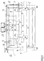
- figure 1 is a front view of said machine;
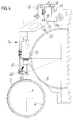
- figures 2 and 3 are respective side views of said machine, taken from opposite sides;
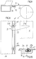
- figure 4 is essentially a partial transverse sectional view of the machine, taken along a vertical plane that lies at right angles to the front of said machine;
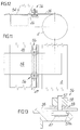
- figure 5 is a detail of the front view;
- figure 6 is essentially a partial horizontal sectional view of the detail of figure 5;
- figure 7 is a view, similar to figure 4, of a more extensively equipped machine;
- figure 8 is a plan view of a detail of figure 7;
- figure 9 is a transverse sectional view of the same detail shown in figure 8;
- figure 10 is an enlarged-scale transverse sectional view of a detail of figure 8;
- figures 11, 12, and 13 are views, similar to figures 8, 9, and 10 respectively, of said detail of figure 7 used differently.
- With particular reference to the above figures, the
reference numerals flexible printing plates 3 on plate-holder cylinders 4 and for printing proofs with the cylinders thus prepared. - A plate-
holder cylinder 4, with its pivot-likeaxial ends 4a, is horizontally and rotatably supported by thesemicircular supports 5, which are positionable along abeam 6. Said beam can move vertically along the guides 7, which lie in front of thesides overlying counterpressure drum 8. - The
drum 8 is rotatably mounted between thesides beam 6; said drum is covered with a sheet of paper provided with registration markings:registration lines 9 and 10 that run respectively along straight generatrices and circular directrices of saidcylinder 8 are usually marked on said sheet. - In the mounting position, the uppermost generatrix of the printing plate, which wraps around the plate-holder cylinder mounted on the
beam 6, is always at the same level and therefore in the same relative arrangement with respect to thecounterpressure drum 8, regardless of the diameter of the plate-holder cylinder and of the thickness of the printing plate. The mounting position is determined by the semitransparent-mirror optical device, with which the machine is frontally provided, said device matching directly-viewed points of the plate-holder cylinder (or rather of a printing plate positioned thereon) in mounting position, with reflected points of the sheet of paper covering the counterpressure drum. - As in conventional machines, such as the one disclosed in Italian patent no. 953251 in the name of the same Applicant, the semitransparent mirror of said device can in practice be as long as the
counterpressure drum 8, to which it is parallel, and can be movably mounted between an active position, which is lowered and lies between said counterpressure drum and a plate-holder cylinder in the mounting position, and a spaced position, which corresponds to proof printing. Of course, this solution, which uses a single long semitransparent mirror, does not need to be shown in the figures. In any case, differently from conventional machines, as will become apparent, in order to provide said desired match between printing plate points and paper sheet points by using the semitransparent mirror, the invention does not make use of the simple and direct sighting performed by the operator of the machine but uses the mediation of video cameras and monitors, thus eliminating awkwardness in sighting, differences among work steps performed by different operators, and sighting errors caused by sight defects and by the positions assumed by the operator's eye. - As in conventional machines, the
counterpressure drum 8 is adapted to cooperate with the plate-holder cylinder 4, which is supported by thebeam 6; the kinematic connection through which this cooperation between thecylinder 4 and thedrum 8 occurs, comprisesrespective gears 11 and 12 and a constant-speed joint, which is not shown. - A
bar 13 lies above the counterpressure drum so that it is parallel thereto and is located in front of the machine; thebar 13 is pivoted at 14, by means of itslugs 13a, to thesides drum 8. At least twovideo cameras 15 are positionable along thebar 13. Each video camera is in fact applied to the central region of a respective box-like shapedcontoured arm 16 which forms aslider 17 in an upward region; said slider is slideably mounted onto thebar 13 by means of a plurality ofrollers 18 and can be locked thereon in the desired position by means of a screw 19 (of its own). - When the two
video cameras 15 are in the active position (with thearm 16 in the position shown in figures 2, 4, and 7), they are directed towards the plate-holder cylinder 4, placed in the mounting position, along respective vertical axes T; said axes intersect said semitransparent-mirror optical device, are substantially perpendicular to the axis S of said plate-holder cylinder, and in practice lie on the vertical plane P through which the axis S passes during the ascending and descending motions of thebeam 6. Instead of having said single long semitransparent mirror, the optical device can have a smallsemitransparent mirror 20, as shown in the figures, on eacharm 16 below the respective video camera. Springs 21 keep thesemitransparent mirrors 20 pressed againstsupports 22 provided on saidarms 16. - When the two
video cameras 15 are in the active position, thebar 13 and itsscrews 23 rest by gravity against thesides arms 16 and the video cameras are raised into the spaced position for proof printing, theroller 24 engages alug 13a of thebar 13; said roller is supported by an eccentric portion of thepivot 25 which is rotatably mounted to thecorresponding side 1. Thelever 26 is keyed on thepivot 25; said lever is generally shown in solid lines and in the condition in which thebar 13 is in the active position, whereas in figure 3 it is also shown in dashed lines and in the condition 26a in which, since theroller 24 has engaged thelug 13a, thearms 16 are in the spaced position 16a, also shown in dashed lines, and theprotrusion 27, which lies radially to the pivot 25 (figure 6), rests onto theabutment 28 rigidly coupled to theside 1. - The
video cameras 15 are connected torespective monitors 29 arranged on a beam that joins the top of thesides - A
respective writing stylus 30 is mounted on at least onearm 16, directly below theslider 17, and is adapted to mark, in a known manner, theregistration lines 9 or 10 when the stylus is actuated and the slider slides along thebar 13 or, respectively, thecylinder 8 turns. - The sliders 17 (and therefore the
arms 16 and the video cameras 15) are connectable, in a mutually exclusive manner, to abelt 31 which is closed in a loop and wraps around thepulleys bar 13. In order to control the movements of the belt 31 (and therefore of the video camera optionally connected thereto) along thebar 13, said belt or said bar can be appropriately graduated. - Otherwise, the
pulley 32 has angularly distributedpins 34 engagingholes 35 which are uniformly distributed along thebelt 31; said pulley is furthermore keyed to the shaft of anencoder 36 connected to a display, not shown. - The
pulley 33 furthermore forms, in an upper region, a set of teeth with which a sprocket 37 meshes; said sprocket can be actuated by means of theknob 38 to make the belt (and therefore the video camera connected thereto) perform limited movements; for large movements it is sufficient to manually drag the video camera (and therefore the belt to which it is optionally connected). - In any case, it should be noted that in view of the selected degree of magnification and of the consequent extent of the surface that can be inspected with the individual video camera, video camera positioning does not require particular accuracy and can therefore be performed very quickly.
-
Respective blocks belt 31 in order to close it in a loop and tension it; screws 41, driven into theblock 40, pass through theblock 39;respective springs 42 are arranged around said screws, between the head of thescrews 41 and theblock 39, and push said block against theblock 40. - In order to connect it to the
belt 31, eachslider 17 has afork 44 pivoted thereto by means of apivot 43; in the active condition, shown in figures 5 and 6, said fork is directed upwards, wraps around theprotrusion 40a of theblock 40, and is fitted thereon. Thepivot 43, passing through the slider, is provided with the rigidly coupledfork 44 at one end and with anactuation lever 45 at the other end; by acting on saidlever 45, the fork assumes the inactive downward-facing condition and, vice versa, the active one. - With reference to figures 7 to 13, the machine for fixing flexible printing plates on plate-holder cylinders and for then printing proofs can also be equipped with a
bar 46 that lies in front of thecounterpressure drum 8, is parallel thereto, and has alongitudinal slot 47 preferably shaped like an inverted T in cross-section. -
Elements 48 can be arranged along the slot 47 (figures 7 to 10); said elements essentially have a cross-section that is complementary to the cross-section of the slot, and protrude thereabove with a sort ofrespective pin 48a. Thepins 48a engage registration holes ofinextensible printing plates 3a provided with holes. In order to lock eachelement 48 in the desired position along theslot 47, a grub screw 49 is screwed into each element and acts on the bottom of said slot; said grub screw can be activated by reaching it through ahole 50 that is coaxial to thepin 48a and is open upwards. - L-shaped
elements 51 can be used to position (and then lock) theelements 48 along theslot 47. Each one of said L-shaped elements in fact has alower portion 52, which can be coupled to the slot with a side-fitting engagement, and has a laminarupper part 53, protruding, when thebar 46 is in the active position, as shown in the figures, towards the plate-holder cylinder 4 until it covers it beyond its uppermost generatrix. Thepart 53 has a longitudinal edge divided into twoportions pin 48a. Theportion 53a is suitable to be located on vertical planes that lie transversely to the plate-holder cylinder 4 and to be moved so that it is aligned, by means of said semitransparent mirrors, video cameras and monitors, withlines 10 applied on said paper sheet. When theportion 53a accordingly matches a desiredline 10, thepin 48a of anelement 48 is arranged adjacent to theportion 53b; said pin also matches the desiredline 10. - The ends of the
bar 46 are supported byrespective arms 54 which are oscillatably mounted on therespective sides axis 55. Accordingly, the bar can stably assume said lowered active position proximate to a plate-holder cylinder placed in the mounting position, or a removed and raised position in which it is possible to print proofs: in this latter position, thearms 54 are in the condition shown partially in dashed lines in figure 7 and designated by thereference numeral 54a. - After the
elements 48 have been positioned and locked along thebar 46 as mentioned, and after the perforated printing plate has engaged thepins 48a and has been placed onto the plate-holder cylinder 4 as shown in figure 7, said printing plate is partially fixed to said cylinder; fixing is then completed, after disengaging the printing plate from the pins and removing thebar 46, and checked by using the semitransparent mirrors, the video cameras and the monitors. In order to fix the printing plate, the non-stick protective film is removed from the outer surface of the material made of double-adhesive sheet applied to the plate-holder cylinder. - Once a first printing plate related to one color has been fixed, and once the proof has been printed with said first printing plate, the video cameras and the monitors can be used to check the fixing of the printing plates related to the other colors to the respective plate-holder cylinders, by referring to the printing of the first color and without the need, especially in the case of inextensible printing plates, to complete the proof with the remaining colors.
- Obviously, in its active position the
bar 46 is particularly advantageous as a service surface for the printing plates to be fixed, even if said printing plates are not perforated and especially if they are large. - In this case, one flap of the printing plate 3b (figures 11 to 13) is placed onto the plate-
holder cylinder 4, positioned in the mounting position, and since said protective film of the double-adhesive sheet has not yet been removed, the flap is correctly positioned on said cylinder by means of the video cameras and monitors. A pair of a sort of lateral clamps 56 is used to lock the printing plate 3b in the correct position and to thebar 46; once said non-stick film has been removed, said flap of the printing plate is fixed to thecylinder 4; the fixing of the printing plate is finally completed after releasing the clamps. Eachclamp 56 is constituted by ascrew 57 thehead 57a whereof is substantially shaped complementarily, in cross-section, with respect to theslot 47; the stem of the screw protrudes above said slot, and the externallyknurled nut 58 is coupled thereto; thewasher 59 is interposed between the nut and the printing plate. - It should particularly be stressed that the system composed of semitransparent mirrors, video cameras, and monitors, as devised above, no longer requires to adjust the angle of the semitransparent mirrors and avoids parallax errors.
- In the practical embodiment of the invention, the materials employed, as well as the shapes and dimensions, may be any according to the requirements.
- Where technical features mentioned in any claim are followed by reference signs, those reference signs have been included for the sole purpose of increasing the intelligibility of the claims and accordingly such reference signs do not have any limiting effect on the interpretation of each element identified by way of example by such reference signs.
Claims (10)
- Machine for mounting flexible printing plates on plate-holder cylinders of flexographic printing machines and for printing proofs with the cylinders thus prepared, said machine being frontally provided with a counterpressure drum and with a beam which are horizontally parallel and movable with respect to each other between a mounting position and a printing position, said counterpressure drum being rotatable and covered with a sheet of paper having registration markings, said beam being provided with supports that rotatably support a plate-holder cylinder, said machine being characterized in that it comprises: an optical device with a semitransparent mirror, adapted to align directly-viewed points of said plate-holder cylinder in mounting position with reflected points of said sheet of paper; at least two video cameras positionable along a bar that lies parallel to said drum and said cylinder and directed towards the plate-holder cylinder, which is in the mounting position, along respective axes that intersect said optical device and are substantially at right angles to the axis of said plate-holder cylinder; and front monitors connected to said respective video cameras.
- Machine according to claim 2, characterized in that said video cameras and monitors form low-magnification systems.
- Machine according to claim 1, characterized in that each one of said video cameras is mounted onto a respective slider which can slide and be locked along said bar and which also includes a small semitransparent mirror constituting said optical device related to said video camera.
- Machine at least according to claim 3, characterized in that a respective writing stylus is mounted on at least one of said sliders for tracing registration lines on said paper sheet that covers said counterpressure drum.
- Machine at least according to claims 3 and 4, characterized in that said sliders are connectable to a belt that is adapted to run between the ends of said bar, means being provided for controlling the extent of the movements of said belt.
- Machine according to one or more of the preceding claims, frontally provided with a counterpressure drum which is mounted horizontally and rotatably and is covered by a paper sheet having registration markings, and with an underlying beam, provided with supports for rotatably supporting a plate-holder cylinder so that it lies parallel to the counterpressure drum, said beam moving vertically between a lower mounting position, for positioning and fixing the printing plates, and a raised printing position, to allow the printing plates to make contact with the counterpressure drum; said machine being characterized in that it comprises: a bar that lies above the counterpressure drum and is parallel thereto; at least two sliders that can slide and be locked upwardly along said bar and are provided, in a downward region, with a respective small semitransparent mirror, which is suitable to align directly-viewed points ox said plate-holder cylinder in the mounting position with reflected points of said paper sheet, said sliders being centrally provided with a respective video camera directed towards the plate-holder cylinder, which is placed in the mounting position, along an axis that intersects said respective small semitransparent mirror and lies substantially at right angles to the axis of said plate-holder cylinder, said video cameras being connected to respective front monitors in low-magnification systems, said bar being oscillatably mounted between an active position and a spaced position in which said small semitransparent mirrors are respectively lowered and intermediate between the counterpressure drum and a plate-holder cylinder in the mounting position and, vice versa, are raised for proofs.
- Machine according to claim 6, characterized in that said sliders are furthermore provided with respective writing styluses that trace registration lines on said paper sheet covering said counterpressure drum and can be connected to a belt running between the ends of said bar, means being provided for controlling the extent of the movements of said belt.
- Machine according to one or more of the preceding claims, characterized in that it furthermore comprises a bar that lies frontally and parallel to the counterpressure drum and has a longitudinal slot for the positioning both of pin elements, adapted to engage registration holes of printing plates, and of L-shaped elements arrangeable adjacent to said pin elements and aligneable, by means of said semitransparent mirrors, video cameras, and monitors, with registration markings applied on said paper sheet along directrices of the counterpressure drum, said bar being oscillatably mounted between an active position and a spaced position, in which it is respectively lowered and proximate to a plate-holder cylinder in the mounting position and raised for proofs.
- Machine according to claim 8, characterized in that said slot of said bar is also suitable for placing clamp-like elements which are adapted to lock the printing plates laterally to said bar.
- Machine at least according to claim 1, characterized in that said semitransparent-mirror optical device lies parallel to said counterpressure drum and is oscillatably mounted between an active position and a spaced position, in which it is respectively lowered and lies between the counterpressure drum and a plate-holder cylinder in the mounting position and is raised for proofs.
Priority Applications (5)
| Application Number | Priority Date | Filing Date | Title |
|---|---|---|---|
| DE69510766T DE69510766T2 (en) | 1995-02-24 | 1995-02-24 | Machine for mounting flexible printing plates on plate cylinders of flexographic printing machines and for taking test prints |
| DK95830052T DK0728580T3 (en) | 1995-02-24 | 1995-02-24 | Machine for mounting flexible printing plates on plate holder cylinders in flexographic printing machines and for printing the sample |
| EP95830052A EP0728580B1 (en) | 1995-02-24 | 1995-02-24 | Machine for mounting flexible printing plates on plate-holder cylinders of flexographic printing machines and for printing proofs |
| ES95830052T ES2133703T3 (en) | 1995-02-24 | 1995-02-24 | MACHINE FOR MOUNTING FLEXIBLE PRINTING PLATES IN CYLINDER HOLDERS FOR FLEXOGRAPHIC PRINTING MACHINES AND FOR PRINTING PROOFS. |
| US08/439,345 US5666881A (en) | 1995-02-24 | 1995-05-11 | Machine for mounting flexible printing plates on plate-holder cylinders of flexographic printing machines and for printing proofs |
Applications Claiming Priority (1)
| Application Number | Priority Date | Filing Date | Title |
|---|---|---|---|
| EP95830052A EP0728580B1 (en) | 1995-02-24 | 1995-02-24 | Machine for mounting flexible printing plates on plate-holder cylinders of flexographic printing machines and for printing proofs |
Publications (2)
| Publication Number | Publication Date |
|---|---|
| EP0728580A1 true EP0728580A1 (en) | 1996-08-28 |
| EP0728580B1 EP0728580B1 (en) | 1999-07-14 |
Family
ID=8221856
Family Applications (1)
| Application Number | Title | Priority Date | Filing Date |
|---|---|---|---|
| EP95830052A Expired - Lifetime EP0728580B1 (en) | 1995-02-24 | 1995-02-24 | Machine for mounting flexible printing plates on plate-holder cylinders of flexographic printing machines and for printing proofs |
Country Status (5)
| Country | Link |
|---|---|
| US (1) | US5666881A (en) |
| EP (1) | EP0728580B1 (en) |
| DE (1) | DE69510766T2 (en) |
| DK (1) | DK0728580T3 (en) |
| ES (1) | ES2133703T3 (en) |
Cited By (11)
| Publication number | Priority date | Publication date | Assignee | Title |
|---|---|---|---|---|
| US5850789A (en) * | 1997-07-22 | 1998-12-22 | E. I. Du Pont De Nemours And Company | Method and apparatus for mounting printing plates |
| EP1060884A1 (en) * | 1999-06-08 | 2000-12-20 | Bieffebi S.p.A. | Mounting device for flexographic printing plates |
| EP1193058A1 (en) * | 2000-09-28 | 2002-04-03 | Bieffebi S.p.A. | Device for transmitting rotary motion to a plate-holding impression cylinder of a plate mounting machine for flexographic printing |
| US6718873B1 (en) | 2003-03-13 | 2004-04-13 | Bieffebi S.P.A. | Proof press for mounting flexographic printing plates |
| GB2398038A (en) * | 2003-02-08 | 2004-08-11 | Flexico Ltd | Apparatus for mounting a printing plate to a printing cylinder |
| NL1023431C2 (en) * | 2003-05-14 | 2004-11-16 | Av Flexologic Bv | Regulated positioning device for flexible printing plates. |
| EP1666251A1 (en) | 2004-12-02 | 2006-06-07 | Bieffebi S.p.A. | Machine for in-register mounting of flexographic printing plates with a virtual data-processing system |
| WO2010146040A1 (en) | 2009-06-16 | 2010-12-23 | Bieffebi - Societa' Per Azioni | Apparatus for checking geometric parameters of printing assemblies constituted by flexographic printing plates mounted on respective rollers, by flexographic printing plates mounted on respective printing plate supporting sleeves and by inking rollers/sleeves |
| CN102759764A (en) * | 2011-04-25 | 2012-10-31 | 奇美实业股份有限公司 | Manufacturing method of micro-structural optical plate with high transcription rate and forming device thereof |
| NL2006897C2 (en) * | 2011-06-06 | 2012-12-10 | Av Flexologic Bv | METHOD AND DEVICE FOR PLACING A PRESSURE PLATE IN ITS REGISTER POSITION. |
| CN104742514A (en) * | 2015-02-26 | 2015-07-01 | 重庆宏劲印务有限责任公司 | Detection method for hot stamping pressure |
Families Citing this family (14)
| Publication number | Priority date | Publication date | Assignee | Title |
|---|---|---|---|---|
| US6113346A (en) | 1996-07-31 | 2000-09-05 | Agfa Corporation | Method for loading and unloading a supply of plates in an automated plate handler |
| US6530771B1 (en) * | 1997-03-14 | 2003-03-11 | Casa Herrera, Inc. | Rotary cutter handling system |
| DE19854845B4 (en) * | 1998-01-30 | 2011-02-24 | Heidelberger Druckmaschinen Ag | Method and device for automatic detection of at least one printing plate edge |
| JP2002120348A (en) * | 2000-10-13 | 2002-04-23 | Komori Corp | Printing press |
| GB2380885A (en) * | 2001-10-11 | 2003-04-16 | Hewlett Packard Co | Multiple camera arrangement |
| US6755132B1 (en) * | 2003-01-22 | 2004-06-29 | Creo Inc. | Registration pin system |
| US7456379B2 (en) * | 2003-02-03 | 2008-11-25 | Kodak Graphic Communications Canada Company | Printing plate registration and optical alignment device including locating at least a part of a reference edge in at least one digital camera image |
| US7275482B2 (en) * | 2004-10-28 | 2007-10-02 | Integrity Engineering, Inc. | Ink proofer arrangement including substrate roll support and tensioner and method of using |
| US7600471B2 (en) | 2005-05-10 | 2009-10-13 | Westby Ronald K | Hand proofer tool |
| US8720335B2 (en) | 2007-04-24 | 2014-05-13 | Probity Engineering, Llc | Offset hand proofer tool |
| WO2010014619A2 (en) | 2008-07-28 | 2010-02-04 | Integrity Engineering, Inc. | Improvements to flexographic proofing tools and methods |
| CN102193119B (en) * | 2010-03-02 | 2014-05-21 | 奇美实业股份有限公司 | Optical plate with micro structures and mark manufacturing method thereof |
| FR3083780B1 (en) * | 2018-07-11 | 2020-09-25 | Asidium | MACHINE AND METHOD FOR FILMING THE TWO SIDES OF A PIECE |
| US11204231B1 (en) * | 2020-03-13 | 2021-12-21 | Industrial Kiln & Dryer Group, Inc. | Device used for aligning a rotatable drum |
Citations (4)
| Publication number | Priority date | Publication date | Assignee | Title |
|---|---|---|---|---|
| FR2170063A1 (en) * | 1972-02-05 | 1973-09-14 | Bieffebi Degli Esposti Franco | |
| EP0089015A1 (en) * | 1982-03-16 | 1983-09-21 | Windmöller & Hölscher | Method of registering and attaching printing plates on the plate cylinder of flexographic multicolour printing machines |
| US4653369A (en) * | 1984-07-09 | 1987-03-31 | Menasha Corporation | Flexographic printing plate mounting method and apparatus |
| US4936212A (en) * | 1989-05-01 | 1990-06-26 | Mosstype Corporation | Flexographic printing plate transfer tray for mounter-proofer machine |
Family Cites Families (3)
| Publication number | Priority date | Publication date | Assignee | Title |
|---|---|---|---|---|
| JPS6149218A (en) * | 1984-08-16 | 1986-03-11 | Shimadzu Corp | Automatic positioning method of screen printer |
| US5317971A (en) * | 1992-08-26 | 1994-06-07 | Deye Jr Charles E | Pin register mounter and method of mounting flexographic plates |
| US5488781A (en) * | 1994-12-13 | 1996-02-06 | Av Flexologic B.V. | Positioning apparatus for printing plates |
-
1995
- 1995-02-24 DK DK95830052T patent/DK0728580T3/en active
- 1995-02-24 EP EP95830052A patent/EP0728580B1/en not_active Expired - Lifetime
- 1995-02-24 DE DE69510766T patent/DE69510766T2/en not_active Expired - Lifetime
- 1995-02-24 ES ES95830052T patent/ES2133703T3/en not_active Expired - Lifetime
- 1995-05-11 US US08/439,345 patent/US5666881A/en not_active Expired - Lifetime
Patent Citations (4)
| Publication number | Priority date | Publication date | Assignee | Title |
|---|---|---|---|---|
| FR2170063A1 (en) * | 1972-02-05 | 1973-09-14 | Bieffebi Degli Esposti Franco | |
| EP0089015A1 (en) * | 1982-03-16 | 1983-09-21 | Windmöller & Hölscher | Method of registering and attaching printing plates on the plate cylinder of flexographic multicolour printing machines |
| US4653369A (en) * | 1984-07-09 | 1987-03-31 | Menasha Corporation | Flexographic printing plate mounting method and apparatus |
| US4936212A (en) * | 1989-05-01 | 1990-06-26 | Mosstype Corporation | Flexographic printing plate transfer tray for mounter-proofer machine |
Cited By (21)
| Publication number | Priority date | Publication date | Assignee | Title |
|---|---|---|---|---|
| US5850789A (en) * | 1997-07-22 | 1998-12-22 | E. I. Du Pont De Nemours And Company | Method and apparatus for mounting printing plates |
| EP0893254A2 (en) * | 1997-07-22 | 1999-01-27 | E.I. Du Pont De Nemours And Company | Method and apparatus for registration mounting printing plates |
| EP0893254A3 (en) * | 1997-07-22 | 1999-06-16 | E.I. Du Pont De Nemours And Company | Method and apparatus for registration mounting printing plates |
| EP1060884A1 (en) * | 1999-06-08 | 2000-12-20 | Bieffebi S.p.A. | Mounting device for flexographic printing plates |
| EP1193058A1 (en) * | 2000-09-28 | 2002-04-03 | Bieffebi S.p.A. | Device for transmitting rotary motion to a plate-holding impression cylinder of a plate mounting machine for flexographic printing |
| US6564709B2 (en) | 2000-09-28 | 2003-05-20 | Bieffebi S.P.A. | Device for transmitting rotary motion to a plate-holding impression cylinder of a plate mounting machine for flexographic printing |
| GB2398038A (en) * | 2003-02-08 | 2004-08-11 | Flexico Ltd | Apparatus for mounting a printing plate to a printing cylinder |
| GB2398038B (en) * | 2003-02-08 | 2005-06-15 | Flexico Ltd | Plate mounting apparatus |
| US6718873B1 (en) | 2003-03-13 | 2004-04-13 | Bieffebi S.P.A. | Proof press for mounting flexographic printing plates |
| EP1457322A1 (en) * | 2003-03-13 | 2004-09-15 | Bieffebi S.p.A. | Proof press for mounting flexographic printing plates |
| EP1477312A1 (en) * | 2003-05-14 | 2004-11-17 | AV Flexologic B.V. | Positioning apparatus provided with a register for flexible printing plates |
| NL1023431C2 (en) * | 2003-05-14 | 2004-11-16 | Av Flexologic Bv | Regulated positioning device for flexible printing plates. |
| US7127993B2 (en) | 2003-05-14 | 2006-10-31 | Av Flexologic B.V. | Positioning apparatus provided with a register for flexible printing plates |
| EP1666251A1 (en) | 2004-12-02 | 2006-06-07 | Bieffebi S.p.A. | Machine for in-register mounting of flexographic printing plates with a virtual data-processing system |
| US8037819B2 (en) | 2004-12-02 | 2011-10-18 | Bieffebi S.P.A. | Machine for in-register mounting of flexographic printing plates |
| WO2010146040A1 (en) | 2009-06-16 | 2010-12-23 | Bieffebi - Societa' Per Azioni | Apparatus for checking geometric parameters of printing assemblies constituted by flexographic printing plates mounted on respective rollers, by flexographic printing plates mounted on respective printing plate supporting sleeves and by inking rollers/sleeves |
| CN102759764A (en) * | 2011-04-25 | 2012-10-31 | 奇美实业股份有限公司 | Manufacturing method of micro-structural optical plate with high transcription rate and forming device thereof |
| CN102759764B (en) * | 2011-04-25 | 2014-09-24 | 奇美实业股份有限公司 | Manufacturing method of micro-structural optical plate with high transcription rate and forming device thereof |
| NL2006897C2 (en) * | 2011-06-06 | 2012-12-10 | Av Flexologic Bv | METHOD AND DEVICE FOR PLACING A PRESSURE PLATE IN ITS REGISTER POSITION. |
| EP2532522A1 (en) * | 2011-06-06 | 2012-12-12 | AV Flexologic B.V. | Method and device for positioning a printing plate in its register position |
| CN104742514A (en) * | 2015-02-26 | 2015-07-01 | 重庆宏劲印务有限责任公司 | Detection method for hot stamping pressure |
Also Published As
| Publication number | Publication date |
|---|---|
| DE69510766D1 (en) | 1999-08-19 |
| DK0728580T3 (en) | 1999-11-29 |
| US5666881A (en) | 1997-09-16 |
| ES2133703T3 (en) | 1999-09-16 |
| EP0728580B1 (en) | 1999-07-14 |
| DE69510766T2 (en) | 2000-01-13 |
Similar Documents
| Publication | Publication Date | Title |
|---|---|---|
| EP0728580B1 (en) | Machine for mounting flexible printing plates on plate-holder cylinders of flexographic printing machines and for printing proofs | |
| US4872407A (en) | Method for the mounting of a flexible printing plate on a cylinder, and apparatus for the execution of the method | |
| US5439328A (en) | Single-head drill with video attachment | |
| US4033259A (en) | Device for adjusting printing plates on the plate cylinder of printing presses | |
| US5132911A (en) | Apparatus for mounting and proofing printing plates | |
| US7647868B2 (en) | Method for feeding a printing forme to a forme cylinder of a printing press | |
| JPS62263053A (en) | Registration error measuring method and device in multi-color printer | |
| CN103648780B (en) | The method of installation and registration galley on the plate cylinder of polychrome offset press | |
| US4226181A (en) | Method and apparatus for adjusting the position of a stencil relative to a printing table | |
| EP0507635B1 (en) | Plate clamping system for a duplicating machine | |
| US5377590A (en) | Method and apparatus for the accurate registering and mounting of printing plates on forme cylinders | |
| US5777878A (en) | Screen printing press having longitudinal, lateral and angular screen frame registration system and method | |
| JP4083261B2 (en) | Silk screen printing machine | |
| US4936212A (en) | Flexographic printing plate transfer tray for mounter-proofer machine | |
| CA2252500C (en) | Printing plate mounting structure | |
| US2745186A (en) | Universal printing plate registering and punching machine | |
| US5445075A (en) | Doubly articulated screen printing apparatus with on-line registration capability | |
| US4613395A (en) | Apparatus for bonding a printing plate on a base film | |
| AU748606B2 (en) | Positioning device of a flexible printing plate on a plate cylinder | |
| US3361060A (en) | Machine for mounting and proofing rubber printing plates | |
| US2736968A (en) | Apparatus for registering printing plates | |
| JPS6210128Y2 (en) | ||
| US4987443A (en) | Method and apparatus for imaging press plates | |
| US4372677A (en) | Precision planar positioning device | |
| JPS622123Y2 (en) |
Legal Events
| Date | Code | Title | Description |
|---|---|---|---|
| PUAI | Public reference made under article 153(3) epc to a published international application that has entered the european phase |
Free format text: ORIGINAL CODE: 0009012 |
|
| AK | Designated contracting states |
Kind code of ref document: A1 Designated state(s): BE CH DE DK ES FR GB IT LI NL PT SE |
|
| 17P | Request for examination filed |
Effective date: 19970122 |
|
| 17Q | First examination report despatched |
Effective date: 19970707 |
|
| GRAG | Despatch of communication of intention to grant |
Free format text: ORIGINAL CODE: EPIDOS AGRA |
|
| GRAG | Despatch of communication of intention to grant |
Free format text: ORIGINAL CODE: EPIDOS AGRA |
|
| GRAH | Despatch of communication of intention to grant a patent |
Free format text: ORIGINAL CODE: EPIDOS IGRA |
|
| GRAH | Despatch of communication of intention to grant a patent |
Free format text: ORIGINAL CODE: EPIDOS IGRA |
|
| GRAA | (expected) grant |
Free format text: ORIGINAL CODE: 0009210 |
|
| AK | Designated contracting states |
Kind code of ref document: B1 Designated state(s): BE CH DE DK ES FR GB IT LI NL PT SE |
|
| REG | Reference to a national code |
Ref country code: CH Ref legal event code: EP |
|
| REF | Corresponds to: |
Ref document number: 69510766 Country of ref document: DE Date of ref document: 19990819 |
|
| ET | Fr: translation filed | ||
| REG | Reference to a national code |
Ref country code: ES Ref legal event code: FG2A Ref document number: 2133703 Country of ref document: ES Kind code of ref document: T3 |
|
| ITF | It: translation for a ep patent filed | ||
| PG25 | Lapsed in a contracting state [announced via postgrant information from national office to epo] |
Ref country code: PT Free format text: LAPSE BECAUSE OF FAILURE TO SUBMIT A TRANSLATION OF THE DESCRIPTION OR TO PAY THE FEE WITHIN THE PRESCRIBED TIME-LIMIT Effective date: 19991014 |
|
| REG | Reference to a national code |
Ref country code: CH Ref legal event code: NV Representative=s name: PATENTANWAELTE SCHAAD, BALASS, MENZL & PARTNER AG |
|
| REG | Reference to a national code |
Ref country code: DK Ref legal event code: T3 |
|
| PLBE | No opposition filed within time limit |
Free format text: ORIGINAL CODE: 0009261 |
|
| STAA | Information on the status of an ep patent application or granted ep patent |
Free format text: STATUS: NO OPPOSITION FILED WITHIN TIME LIMIT |
|
| 26N | No opposition filed | ||
| REG | Reference to a national code |
Ref country code: GB Ref legal event code: IF02 |
|
| PGFP | Annual fee paid to national office [announced via postgrant information from national office to epo] |
Ref country code: SE Payment date: 20080228 Year of fee payment: 14 |
|
| PGFP | Annual fee paid to national office [announced via postgrant information from national office to epo] |
Ref country code: CH Payment date: 20090227 Year of fee payment: 15 |
|
| EUG | Se: european patent has lapsed | ||
| PGFP | Annual fee paid to national office [announced via postgrant information from national office to epo] |
Ref country code: DK Payment date: 20100326 Year of fee payment: 16 |
|
| PGFP | Annual fee paid to national office [announced via postgrant information from national office to epo] |
Ref country code: FR Payment date: 20100311 Year of fee payment: 16 |
|
| REG | Reference to a national code |
Ref country code: CH Ref legal event code: PL |
|
| PG25 | Lapsed in a contracting state [announced via postgrant information from national office to epo] |
Ref country code: LI Free format text: LAPSE BECAUSE OF NON-PAYMENT OF DUE FEES Effective date: 20100228 Ref country code: CH Free format text: LAPSE BECAUSE OF NON-PAYMENT OF DUE FEES Effective date: 20100228 |
|
| PG25 | Lapsed in a contracting state [announced via postgrant information from national office to epo] |
Ref country code: SE Free format text: LAPSE BECAUSE OF NON-PAYMENT OF DUE FEES Effective date: 20090225 |
|
| REG | Reference to a national code |
Ref country code: DK Ref legal event code: EBP |
|
| REG | Reference to a national code |
Ref country code: FR Ref legal event code: ST Effective date: 20111102 |
|
| PG25 | Lapsed in a contracting state [announced via postgrant information from national office to epo] |
Ref country code: FR Free format text: LAPSE BECAUSE OF NON-PAYMENT OF DUE FEES Effective date: 20110228 |
|
| PGFP | Annual fee paid to national office [announced via postgrant information from national office to epo] |
Ref country code: DE Payment date: 20120218 Year of fee payment: 18 |
|
| PGFP | Annual fee paid to national office [announced via postgrant information from national office to epo] |
Ref country code: IT Payment date: 20120224 Year of fee payment: 18 |
|
| PGFP | Annual fee paid to national office [announced via postgrant information from national office to epo] |
Ref country code: GB Payment date: 20130227 Year of fee payment: 19 |
|
| PGFP | Annual fee paid to national office [announced via postgrant information from national office to epo] |
Ref country code: NL Payment date: 20130224 Year of fee payment: 19 Ref country code: BE Payment date: 20130227 Year of fee payment: 19 |
|
| PGFP | Annual fee paid to national office [announced via postgrant information from national office to epo] |
Ref country code: ES Payment date: 20120216 Year of fee payment: 18 |
|
| REG | Reference to a national code |
Ref country code: DE Ref legal event code: R119 Ref document number: 69510766 Country of ref document: DE Effective date: 20130903 |
|
| PG25 | Lapsed in a contracting state [announced via postgrant information from national office to epo] |
Ref country code: DE Free format text: LAPSE BECAUSE OF NON-PAYMENT OF DUE FEES Effective date: 20130903 |
|
| REG | Reference to a national code |
Ref country code: ES Ref legal event code: FD2A Effective date: 20140408 |
|
| PG25 | Lapsed in a contracting state [announced via postgrant information from national office to epo] |
Ref country code: ES Free format text: LAPSE BECAUSE OF NON-PAYMENT OF DUE FEES Effective date: 20130225 |
|
| BERE | Be: lapsed |
Owner name: *BIEFFEBI S.P.A. Effective date: 20140228 |
|
| REG | Reference to a national code |
Ref country code: NL Ref legal event code: V1 Effective date: 20140901 |
|
| GBPC | Gb: european patent ceased through non-payment of renewal fee |
Effective date: 20140224 |
|
| PG25 | Lapsed in a contracting state [announced via postgrant information from national office to epo] |
Ref country code: NL Free format text: LAPSE BECAUSE OF NON-PAYMENT OF DUE FEES Effective date: 20140901 |
|
| PG25 | Lapsed in a contracting state [announced via postgrant information from national office to epo] |
Ref country code: GB Free format text: LAPSE BECAUSE OF NON-PAYMENT OF DUE FEES Effective date: 20140224 Ref country code: BE Free format text: LAPSE BECAUSE OF NON-PAYMENT OF DUE FEES Effective date: 20140228 |
|
| PG25 | Lapsed in a contracting state [announced via postgrant information from national office to epo] |
Ref country code: IT Free format text: LAPSE BECAUSE OF NON-PAYMENT OF DUE FEES Effective date: 20140224 |