EP0728255B1 - Ballon regulateur pour effluents polyphasiques et moyens de prelevements associes - Google Patents
Ballon regulateur pour effluents polyphasiques et moyens de prelevements associes Download PDFInfo
- Publication number
- EP0728255B1 EP0728255B1 EP95925040A EP95925040A EP0728255B1 EP 0728255 B1 EP0728255 B1 EP 0728255B1 EP 95925040 A EP95925040 A EP 95925040A EP 95925040 A EP95925040 A EP 95925040A EP 0728255 B1 EP0728255 B1 EP 0728255B1
- Authority
- EP
- European Patent Office
- Prior art keywords
- flask
- extraction means
- polyphasic
- section
- effluent
- Prior art date
- Legal status (The legal status is an assumption and is not a legal conclusion. Google has not performed a legal analysis and makes no representation as to the accuracy of the status listed.)
- Expired - Lifetime
Links
- 238000000605 extraction Methods 0.000 title claims 16
- 239000012530 fluid Substances 0.000 claims description 32
- 230000001105 regulatory effect Effects 0.000 claims description 25
- 238000012546 transfer Methods 0.000 claims description 10
- 239000012071 phase Substances 0.000 claims description 5
- 238000011144 upstream manufacturing Methods 0.000 claims description 5
- 239000007791 liquid phase Substances 0.000 claims description 4
- 238000000034 method Methods 0.000 claims description 4
- 230000001276 controlling effect Effects 0.000 claims description 3
- 238000013016 damping Methods 0.000 claims 1
- 238000005070 sampling Methods 0.000 description 28
- 238000004519 manufacturing process Methods 0.000 description 15
- 239000007788 liquid Substances 0.000 description 14
- 239000007789 gas Substances 0.000 description 12
- 230000000694 effects Effects 0.000 description 5
- 238000005086 pumping Methods 0.000 description 5
- 238000010586 diagram Methods 0.000 description 3
- 239000000203 mixture Substances 0.000 description 3
- 238000012986 modification Methods 0.000 description 3
- 230000004048 modification Effects 0.000 description 3
- 230000006978 adaptation Effects 0.000 description 2
- 239000007787 solid Substances 0.000 description 2
- XLYOFNOQVPJJNP-UHFFFAOYSA-N water Substances O XLYOFNOQVPJJNP-UHFFFAOYSA-N 0.000 description 2
- 238000012935 Averaging Methods 0.000 description 1
- 238000013461 design Methods 0.000 description 1
- 210000004907 gland Anatomy 0.000 description 1
- 239000003208 petroleum Substances 0.000 description 1
- 239000004576 sand Substances 0.000 description 1
- 230000003068 static effect Effects 0.000 description 1
- 238000001356 surgical procedure Methods 0.000 description 1
Images


Classifications
-
- B—PERFORMING OPERATIONS; TRANSPORTING
- B01—PHYSICAL OR CHEMICAL PROCESSES OR APPARATUS IN GENERAL
- B01D—SEPARATION
- B01D19/00—Degasification of liquids
- B01D19/0063—Regulation, control including valves and floats
-
- E—FIXED CONSTRUCTIONS
- E21—EARTH OR ROCK DRILLING; MINING
- E21B—EARTH OR ROCK DRILLING; OBTAINING OIL, GAS, WATER, SOLUBLE OR MELTABLE MATERIALS OR A SLURRY OF MINERALS FROM WELLS
- E21B43/00—Methods or apparatus for obtaining oil, gas, water, soluble or meltable materials or a slurry of minerals from wells
- E21B43/34—Arrangements for separating materials produced by the well
-
- F—MECHANICAL ENGINEERING; LIGHTING; HEATING; WEAPONS; BLASTING
- F16—ENGINEERING ELEMENTS AND UNITS; GENERAL MEASURES FOR PRODUCING AND MAINTAINING EFFECTIVE FUNCTIONING OF MACHINES OR INSTALLATIONS; THERMAL INSULATION IN GENERAL
- F16K—VALVES; TAPS; COCKS; ACTUATING-FLOATS; DEVICES FOR VENTING OR AERATING
- F16K5/00—Plug valves; Taps or cocks comprising only cut-off apparatus having at least one of the sealing faces shaped as a more or less complete surface of a solid of revolution, the opening and closing movement being predominantly rotary
- F16K5/04—Plug valves; Taps or cocks comprising only cut-off apparatus having at least one of the sealing faces shaped as a more or less complete surface of a solid of revolution, the opening and closing movement being predominantly rotary with plugs having cylindrical surfaces; Packings therefor
- F16K5/0421—Fixed plug and turning sleeve
-
- Y—GENERAL TAGGING OF NEW TECHNOLOGICAL DEVELOPMENTS; GENERAL TAGGING OF CROSS-SECTIONAL TECHNOLOGIES SPANNING OVER SEVERAL SECTIONS OF THE IPC; TECHNICAL SUBJECTS COVERED BY FORMER USPC CROSS-REFERENCE ART COLLECTIONS [XRACs] AND DIGESTS
- Y10—TECHNICAL SUBJECTS COVERED BY FORMER USPC
- Y10T—TECHNICAL SUBJECTS COVERED BY FORMER US CLASSIFICATION
- Y10T137/00—Fluid handling
- Y10T137/0318—Processes
- Y10T137/0324—With control of flow by a condition or characteristic of a fluid
- Y10T137/0357—For producing uniform flow
-
- Y—GENERAL TAGGING OF NEW TECHNOLOGICAL DEVELOPMENTS; GENERAL TAGGING OF CROSS-SECTIONAL TECHNOLOGIES SPANNING OVER SEVERAL SECTIONS OF THE IPC; TECHNICAL SUBJECTS COVERED BY FORMER USPC CROSS-REFERENCE ART COLLECTIONS [XRACs] AND DIGESTS
- Y10—TECHNICAL SUBJECTS COVERED BY FORMER USPC
- Y10T—TECHNICAL SUBJECTS COVERED BY FORMER US CLASSIFICATION
- Y10T137/00—Fluid handling
- Y10T137/2496—Self-proportioning or correlating systems
- Y10T137/2499—Mixture condition maintaining or sensing
-
- Y—GENERAL TAGGING OF NEW TECHNOLOGICAL DEVELOPMENTS; GENERAL TAGGING OF CROSS-SECTIONAL TECHNOLOGIES SPANNING OVER SEVERAL SECTIONS OF THE IPC; TECHNICAL SUBJECTS COVERED BY FORMER USPC CROSS-REFERENCE ART COLLECTIONS [XRACs] AND DIGESTS
- Y10—TECHNICAL SUBJECTS COVERED BY FORMER USPC
- Y10T—TECHNICAL SUBJECTS COVERED BY FORMER US CLASSIFICATION
- Y10T137/00—Fluid handling
- Y10T137/2496—Self-proportioning or correlating systems
- Y10T137/2559—Self-controlled branched flow systems
- Y10T137/2562—Dividing and recombining
Definitions
- the present invention relates to a regulating flask for multiphase fluids and the associated means of sampling.
- the object of the invention is to provide a device which allows better control control of multiphase flow.
- the sampling means have adjustable sampling sections.
- the adjustable passage sections are distributed at different heights, for example on a vertical or inclined line, on either side of the area or interface separating gas, liquid in normal operation. So a variation of position of the interface results in an automatic level regulation effect.
- the sampling means according to the present invention can be said to variable geometry.
- the regulating tank plays the role of a buffer tank due to the time of residence of the multiphase fluid within the capacity it represents.
- the present invention ensures operation satisfactory with a multiphase pumping means although the conditions physics of the multiphase fluid to be pumped (in particular the GLR, pressure ...) varies on a wide beach.
- GLR Gel to Liquid Ratio
- the present invention is perfectly suited to the petroleum field. Indeed, some producing wells provide a liquid mixture (oil and / or water) and gas that should be transferred to a site of use or storage. The transfer is traditionally done by separating the gas and the liquid, then by compressing the gas and pumping the liquid separately. Using a pump multiphase allows to route the gas and liquid assembly in a single surgery. The multiphase pumps used to perform this kind of transfer accept a limited variation of GLR at their limited entry. To adapt the operation of these pumps to the characteristics of the fluid from producing wells, it is necessary to interpose between the wells and the pump, a regulating tank.
- the object of the present invention is to provide an improved regulating balloon, allowing an adaptation, possibly permanent, of the means of samples from variations in the flow conditions of the well, in particular at the variation of its composition.
- the present invention relates to a balloon comprising at least one means of samples of the fluid contained in this balloon, said sampling means includes a passage section for the withdrawal of said fluid which extends over a substantial portion of the height of said balloon.
- the balloon according to the invention is characterized in that the means of sampling include means of modifications of said passage section.
- the means of sampling and modifications of the passage section may have at least two perforated surfaces which move one by relative to the other so as to modify said passage section.
- These surfaces can be cylinders of revolution, preferably coaxial.
- One of the cylinders may be fixed relative to said balloon and the other mobile in rotation about its axis of revolution and the movable cylinder may include means for rotating outside said balloon.
- the cylindrical tubes may be vertical when the ball is in the position of operation.
- the balloon according to the invention may include a cylindrical envelope.
- the cylindrical envelope and the sampling means can be positioned one by the other so that in the operating position the axis of the envelope cylindrical either vertical or horizontal.
- the passage section of the sampling means may be located substantially on the side opposite the fluid inlet opening in the regulating flask, this relative to the axis of the means of sampling.
- the means of sampling may include at least one fixed section located at the bottom of said means of sampling for removal of a liquid phase.
- the means of sampling may include at least one fixed section located at the top of said means of sampling for sampling a gas phase.
- the sampling means can be connected to the suction of a pump multiphase.
- the means of modification of the passage section may be controlled by function of one or more quantities linked to the physical conditions of the fluid to process upstream and / or in the buffer tank and mechanical conditions of the pump operation.
- the references 1 and 2 designate two production zones oil. Each may include several production wells 1a, 1b, 1c, 2a, 2b, 2c, the entire production of each of the zones being collected by a 1d, 2d pipeline for zones 1 and 2.
- Line 3 connects the first site of oil production at a pumping station.
- Line 4 connects the station to pumping 5 to all of the producing wells in the second zone.
- Different collector lines from different production sites reach the station pumping 5 such as lines 6, 7 and 8.
- the production from these different lines are collected by a collector 9 which feeds the balloon regulator 10.
- This balloon is connected to the suction of a pump 11 driven by a possibly electric motor 12.
- the fluid pumped by pump 11 is routed through line 13 to a destination not represented by example a main platform according to the diagrams illustrated by patent US-5,226,482 the content of which is deemed to be part of this text.
- Such a scheme finds particular application in the field of marine production (see Figure 2).
- the set of wells 1 is connected to a buoy floating 14 by a flexible line 15.
- This flexible line can have the shape of an S thanks in particular to the use of a buoy 16.
- On the buoy 14 are in particular the regulating balloon 10, the pump 11 and the drive motor 12.
- the system shown in Figure 2 can cause changes in changing characteristics of the fluid to be pumped at the inlet of the pump. Indeed, the S shape and the back and forth vertical movements of the two loops 17 and 18 of the hose cause variations in the flow characteristics multiphase which are superimposed on the variations of GLR of the effluent at the outlet multiphase wells. These variations relate in particular to the type multiphase flow, GLR ...
- Curve 19 represents the variation in GLR obtained at the entry of the balloon regulator 22 for a multiphase fluid coming from a well at a given time from production. We note that this curve presents many variations brutal for GLR values.
- the characteristics of the fluid coming from the well may have to change, in particular the value of its GLR.
- the ball regulator and its means of sampling are no longer adapted so optimum, and the damped curve 20 then turns into a curve 21 which has variations in amplitudes greater than those of curve 20.
- the present invention makes it possible to reduce the fluctuations of the curve 21 to a level lower, for example at a level similar to that of curve 20, thanks to the use of adjustable direct debits, even though the conditions of production of the multiphase fluid at the inlet of the regulating flask have changed.
- the invention is applicable to any other situation where such variations and amplitudes can be observed, whether on a land or underwater site.
- the device according to the present invention can be used to control flows which are disturbed in particular due to pipes or for adapting to changes in well production or the number of wells production.
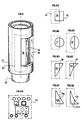
- FIG. 4 schematically shows the device according to the invention.
- the reference 22 designates the regulating flask
- reference 23 the fluid inlet pipe multiphase to be treated opening into the regulating flask through an orifice 33.
- the fluid pours into the regulating flask or capacity 22 and separates into a gas phase 24 and a liquid phase 25 possibly comprising solid like sand.
- the sampling means according to the invention designated in its together by the reference 26 comprises in the particular embodiment of Figure 4, a first outer tube or cylinder 27 surrounding a cylinder inner 28.
- the outer cylinder 27 can rotate on itself relative to its axis of revolution 29 by means of control 30.
- the outer tube 27 comprises for example several openings 31 and the inner tube 28 comprises openings 32.
- the openings or recesses 31 and 32 cooperate together to delimit the passage section H of the effluent or multiphase fluid.
- the flow section will be a function for example of variations in the effluent GLR multiphase to be treated.
- openings or passage openings 32 and 31 are located on the side opposite the inlet opening of the multiphase fluid 33 in the balloon, relative to the axis of revolution 29 of the tubes 27 and 28 which are coaxial. This preserves the openings 31 and 32 of the eddies which may result from the introduction of the multiphase fluid into the regulating flask.
- FIG. 6 is a perspective view of the operation of the cylinders 27 and 28.
- the reference 34 designates the opening of the inner tube 28 while the reference 35 designates the opening of the outer tube 27.
- the overlap zone 36 corresponds to the area actually offered for the passage of the multiphase fluid.
- FIG. 6A have been developed showing the cross sections cylinders 28 and 27 corresponding respectively to openings 34 and 35.
- FIG. 6A the opening 34 of the internal tube and the opening 35 of the external tube are rectangular.
- the shape of the passage section actually offered to the multiphase effluent is a rectangular shape.
- Figures 6A to 6H represent in a nonlimiting manner different forms of possible openings tubes 27 and 28.
- the shape of the opening made up on the inner tube is always rectangular.
- the shape of the opening made on the outer tube 27 is a circle.
- Cooperation openings in the inner tube and the outer tube allow free circle segment 37.
- the free section is a segment of ellipse 38.
- FIG. 6D represents for the external tube, a form of opening triangular 39.
- the passage section 40 due to the cooperation of the two tubes a in this case the shape of a trapezoid.
- one of the sides of the triangle 39 a replaced by a curved curve to better adapt the shape of the opening 41 with the characteristics of the multiphase fluid.
- FIGS. 6F and 6G there are symmetrical shapes with regard to the forms of opening of the external tube shown in FIGS. 6D and 6E. They are referenced respectively 39a and 41a giving a passage section 40a and 42a respectively. It is certain that other forms may be used to solve the problem according to the present invention, as in the figure 6H, the openings of the inner tube may be multiple and have shapes circular as well as the shapes of the openings of the outer tube 43.
- FIG. 5 has been shown, in more detail, an embodiment sampling means according to the present invention.
- the inner tube 28 is secured to the wall 44 of the regulating flask while the outer tube 27 is integral with a rod 45 which passes through a cable gland 46 making it possible to ensure the seal between the internal zone 47 of the regulating flask and the external medium 48.
- the rod 45 allows by means of rotation indicated by the arrows 49 to make vary the opening area left free when passing the multiphase effluent. This zone resulting from the cooperation of the tubes 27 and 28.
- the rod 45 may be provided with a translational movement represented by the arrow 50 allowing in particular to vary the section of passage reserved for multiphase effluent.
- the inner tube 28 has at its base of passage openings 51 which are not covered by the tube outer 27.
- the outer tube 27 has through holes 52 to its upper part which are not covered by the inner tube 28.
- the effluent multiphase arriving through orifice 33 enters capacity 22 where it separates on the one hand in a liquid part, reference 25 and on the other hand in a part gas reference 24.
- the openings represented by reference 54 Figure 4) allow the passage of gas while the openings referenced 55 ( Figure 4) allow the passage of liquid. If the liquid level in the buffer tank increases, the area or section reserved for the passage of liquid will increase, and the zone or section reserved for the passage of the gaseous effluent will be reduced. This results from the fact that the ball has a self-regulating characteristic of the multiphase flow already described in patent FR 2,642,539.
- This effect is obtained by varying the position of the envelope or tube outer 27 relative to the inner tube 28.
- This position can be varied by function, for example, of variations in the GLR of the multiphase fluid detected at the entrance to the buffer tank.
- We can decide to perform movements of the outer tube relative to the inner tube for example after averaging over a certain period of variations in the GLR at the entry of the regulating balloon.
- the control of the position of the outer tube relative to the inner tube can be performed using a computer referenced 56 in FIG. 7.
- This computer can take into account the parameters of the upstream flow of the multiphase effluent, for example the thermodynamic parameters determined using temperature pressure sensors and possibly the value of the flow rate of the effluent determined by an appropriate device. , the assembly of this sensor being referenced 58 in the figure. The parameters are transmitted by a line 57 to the computer.
- the assembly of this upstream sensor is located substantially at the bottom of the water. Of course, it will not depart from the scope of the present invention by placing it at another location in the upstream circuit, for example in the vicinity of the wellhead.
- This assembly may include, in particular, a static pressure tap and a dynamic pressure tap.
- the computer will be able to take into account the variations in the difference of the pressure values of these two taps.
- this computer can take into account the parameters represented the operating conditions of the pump 59 by means of sensors connected by the line 60, for example by measuring the torque and the speed of rotation of the pump. Similarly, it is possible to determine, using appropriate sensors, the pressure and the flow rate of the multiphase effluent at the outlet of the pump. The computer can also take into account the value of the level of the liquid in the regulating flask, this thanks to a sensor 61 connected to the calculator by the line 62. Finally, it is also possible to measure by a sensor 63 the pressure prevailing in the regulating flask and transmit it via line 64 to the computer.
- This computer by integrating these different data will act on the relative position of the cylinders 27 and 28 in order to best adjust the characteristics of the passage section reserved for the multiphase effluent.
- Those skilled in the art will be able to determine the different forms of passage section H as a function of the requirements linked to each production scheme.
Landscapes
- Engineering & Computer Science (AREA)
- Geology (AREA)
- Life Sciences & Earth Sciences (AREA)
- General Engineering & Computer Science (AREA)
- Mining & Mineral Resources (AREA)
- Geochemistry & Mineralogy (AREA)
- Fluid Mechanics (AREA)
- General Life Sciences & Earth Sciences (AREA)
- Physics & Mathematics (AREA)
- Chemical & Material Sciences (AREA)
- Chemical Kinetics & Catalysis (AREA)
- Environmental & Geological Engineering (AREA)
- Mechanical Engineering (AREA)
- Sampling And Sample Adjustment (AREA)
- Physical Or Chemical Processes And Apparatus (AREA)
- Loading And Unloading Of Fuel Tanks Or Ships (AREA)
- Flow Control (AREA)
Applications Claiming Priority (3)
| Application Number | Priority Date | Filing Date | Title |
|---|---|---|---|
| FR9408766 | 1994-07-13 | ||
| FR9408766A FR2722587B1 (fr) | 1994-07-13 | 1994-07-13 | Ballon regulateur pour effluents poloyphasiques etmoyens de prelevements associes |
| PCT/FR1995/000930 WO1996002732A1 (fr) | 1994-07-13 | 1995-07-11 | Ballon regulateur pour effluents polyphasiques et moyens de prelevements associes |
Publications (2)
| Publication Number | Publication Date |
|---|---|
| EP0728255A1 EP0728255A1 (fr) | 1996-08-28 |
| EP0728255B1 true EP0728255B1 (fr) | 2000-12-06 |
Family
ID=9465402
Family Applications (1)
| Application Number | Title | Priority Date | Filing Date |
|---|---|---|---|
| EP95925040A Expired - Lifetime EP0728255B1 (fr) | 1994-07-13 | 1995-07-11 | Ballon regulateur pour effluents polyphasiques et moyens de prelevements associes |
Country Status (6)
| Country | Link |
|---|---|
| US (1) | US5711338A (da) |
| EP (1) | EP0728255B1 (da) |
| DK (1) | DK0728255T3 (da) |
| FR (1) | FR2722587B1 (da) |
| NO (1) | NO312256B1 (da) |
| WO (1) | WO1996002732A1 (da) |
Families Citing this family (11)
| Publication number | Priority date | Publication date | Assignee | Title |
|---|---|---|---|---|
| US6164308A (en) | 1998-08-28 | 2000-12-26 | Butler; Bryan V. | System and method for handling multiphase flow |
| US6234030B1 (en) | 1998-08-28 | 2001-05-22 | Rosewood Equipment Company | Multiphase metering method for multiphase flow |
| MY123548A (en) * | 1999-11-08 | 2006-05-31 | Shell Int Research | Method and system for suppressing and controlling slug flow in a multi-phase fluid stream |
| FR2808455B1 (fr) * | 2000-05-03 | 2003-02-14 | Schlumberger Services Petrol | Installation et procede pour la separation d'effluents multiphasiques |
| WO2002031309A2 (en) * | 2000-10-13 | 2002-04-18 | Schlumberger Technology B.V. | Methods and apparatus for separating fluids |
| DE102004024833A1 (de) * | 2004-05-19 | 2005-12-29 | Universität Rostock | Vorrichtung zur Regelung des Füllstands von Medium in einem Kulturgefäß |
| NO337168B1 (no) | 2012-07-05 | 2016-02-01 | Fmc Kongsberg Subsea As | Apparat og fremgangsmåte for miksing av i det minste en første og andre fluidfase |
| US10208745B2 (en) | 2015-12-18 | 2019-02-19 | General Electric Company | System and method for controlling a fluid transport system |
| US20190271428A1 (en) * | 2018-03-01 | 2019-09-05 | Swan Products, Llc | Adjustable multi-port connector and valve |
| EP4309758A1 (fr) * | 2022-07-21 | 2024-01-24 | Illinois Tool Works Inc. | Réservoir de dégazage |
| US20240173649A1 (en) * | 2022-11-28 | 2024-05-30 | Ronald Williams | Methods to drawdown pipe sections with the use or regulation control of flaring and cross-compression technique |
Family Cites Families (14)
| Publication number | Priority date | Publication date | Assignee | Title |
|---|---|---|---|---|
| US1011482A (en) * | 1911-06-15 | 1911-12-12 | Walter Pemberton | Apparatus for filtering and extracting suspended matter from boiler feed-water under pressure. |
| US1290513A (en) * | 1918-07-30 | 1919-01-07 | Charles S Collins | Proportioning-regulator for fluids. |
| DE842124C (de) * | 1950-12-05 | 1952-06-23 | Goesta W Moeller | Vorrichtung zum selbsttaetigen Regeln der Durchstroemung von Fluessigkeitsmengen in Fluessigkeitsbehaeltern |
| US3025880A (en) * | 1957-06-21 | 1962-03-20 | Borg Warner | Sleeve valves |
| US3208719A (en) * | 1962-08-28 | 1965-09-28 | Drilling Tools Inc | Rotary sleeve valves |
| GB1129506A (en) * | 1967-03-28 | 1968-10-09 | Henry Jones | Improvements in apparatus for discharging liquids at a constant rate |
| HU195628B (en) * | 1985-06-25 | 1988-06-28 | Koebanyai Soergyar | Apparatus for controlling the time of physical changes and/or chemical reactions in flowing medium |
| HU212788B (en) * | 1988-03-10 | 1996-11-28 | Pinter Merrill E | Combined regulator of liquid level and pressure for a separator |
| US5254292A (en) * | 1989-02-02 | 1993-10-19 | Institut Francais Du Petrole | Device for regulating and reducing the fluctuations in a polyphasic flow, and its use |
| FR2642539B1 (fr) * | 1989-02-02 | 1995-12-08 | Inst Francais Du Petrole | Dispositif de regulation et d'amortissement d'un ecoulement polyphasique et son application |
| US5194344A (en) * | 1991-03-26 | 1993-03-16 | Micron Technology, Inc. | Method of fabricating phase shift reticles including chemically mechanically planarizing |
| EP0549440B1 (fr) * | 1991-12-27 | 1996-10-16 | Institut Français du Pétrole | Procédé d'optimisation d'un dispositif de régulation et d'amortissement d'un écoulement polyphasique et dispositif obtenu par le procédé |
| FR2694824B1 (fr) * | 1992-08-11 | 1994-09-16 | Inst Francais Du Petrole | Dispositif de régulation et de distribution d'un fluide polyphasique. |
| FR2699986B1 (fr) * | 1992-12-29 | 1995-02-24 | Inst Francais Du Petrole | Dispositif et méthode permettant de transférer dans une seule conduite un effluent de type polyphasique. |
-
1994
- 1994-07-13 FR FR9408766A patent/FR2722587B1/fr not_active Expired - Fee Related
-
1995
- 1995-07-11 DK DK95925040T patent/DK0728255T3/da active
- 1995-07-11 US US08/615,267 patent/US5711338A/en not_active Expired - Fee Related
- 1995-07-11 WO PCT/FR1995/000930 patent/WO1996002732A1/fr not_active Ceased
- 1995-07-11 EP EP95925040A patent/EP0728255B1/fr not_active Expired - Lifetime
-
1996
- 1996-03-12 NO NO19961012A patent/NO312256B1/no not_active IP Right Cessation
Also Published As
| Publication number | Publication date |
|---|---|
| WO1996002732A1 (fr) | 1996-02-01 |
| EP0728255A1 (fr) | 1996-08-28 |
| NO961012L (no) | 1996-03-12 |
| DK0728255T3 (da) | 2000-12-27 |
| NO312256B1 (no) | 2002-04-15 |
| NO961012D0 (no) | 1996-03-12 |
| FR2722587A1 (fr) | 1996-01-19 |
| US5711338A (en) | 1998-01-27 |
| FR2722587B1 (fr) | 1996-08-30 |
Similar Documents
| Publication | Publication Date | Title |
|---|---|---|
| EP0728255B1 (fr) | Ballon regulateur pour effluents polyphasiques et moyens de prelevements associes | |
| FR2609311A1 (fr) | Echangeur de pression pour liquides | |
| AU2008346913A1 (en) | Apparatus for reducing water production in gas wells | |
| EP1073823A1 (fr) | Procede et dispositif de liaison fond-surface par conduite sous-marine installee a grande profondeur | |
| FR2924364A1 (fr) | Dispositif separateur a cyclone, en particulier pour la separation gaz-huile | |
| FR2516977A1 (fr) | Dispositif de propulsion marine comportant un dispositif mecanique a commande par pression de carburant pour l'amenee d'un melange carburant/huile | |
| EP0435716B1 (fr) | Dispositif de séparation d'un mélange de gaz libre et de liquide à l'admission d'une pompe au fond d'un puits foré | |
| FR2652610A1 (fr) | Procede de pompage de melange liquide gaz dans un puits d'extraction petrolier et dispositif de mise en óoeuvre du procede. | |
| FR2528918A1 (fr) | Dispositif d'etancheite d'un arbre dans une pompe centrifuge et procede pour l'utilisation de ce dispositif | |
| FR2727475A1 (fr) | Methode et systeme de pompage comportant une pompe volumetrique entrainee par un tube continu - application aux puits devies | |
| FR2783514A3 (fr) | Unite hydraulique de levage rapide utilisee dans un verin | |
| FR2787827A1 (fr) | Methode de reglage a une valeur objectif d'un niveau de liquide de forage dans un tube prolongateur d'une installation de forage d'un puits et dispositif pour la mise en oeuvre de cette methode | |
| EP3334898B1 (fr) | Installation sous-marine de séparation gaz/liquide | |
| WO1990008585A1 (fr) | Dispositif de regulation et d'amortissement d'un ecoulement polyphasique et son application | |
| FR2585775A1 (fr) | Pompe a carburant/huile, moteur a combustion interne comportant une telle pompe et dispositif a interrupteur sensible a une pression d'huile et utilisable dans une telle pompe et un tel moteur | |
| EP0478421B1 (fr) | Dispositif d'étanchéité à joint fluide | |
| FR2994229A1 (fr) | Installation de pompage pour puits profond | |
| FR2865506A1 (fr) | Procede perfectionne d'entrainement en rotation d'une roue a aubes et roue a aubes permettant de mettre en oeuvre ce procede | |
| FR2545886A1 (fr) | Pompe de puits comprenant une tige de piston destinee a etre actionnee par une eolienne | |
| FR2621083A1 (fr) | Pompe immergee de prelevement de liquide dans une conduite, notamment une conduite de rejet en eau profonde d'eaux de refroidissement de centrale nucleaire | |
| WO1989011038A2 (fr) | Dispositif de pompage polyphasique a piston et applications de ce dispositif | |
| FR2697870A1 (fr) | Pompe axiale à faible débit. | |
| EP0581636B1 (fr) | Redresseur de flux pour poste de detente et dispositif de comptage | |
| BE881577R (fr) | Dispositif de lutte contre la pollution thermique des rivieres, plans d'eau et analogues | |
| EP0105997A1 (fr) | Procédé et dispositif pour le transfert de liquides par aspiration |
Legal Events
| Date | Code | Title | Description |
|---|---|---|---|
| PUAI | Public reference made under article 153(3) epc to a published international application that has entered the european phase |
Free format text: ORIGINAL CODE: 0009012 |
|
| AK | Designated contracting states |
Kind code of ref document: A1 Designated state(s): DK GB IT NL |
|
| 17P | Request for examination filed |
Effective date: 19960801 |
|
| 17Q | First examination report despatched |
Effective date: 19990322 |
|
| GRAG | Despatch of communication of intention to grant |
Free format text: ORIGINAL CODE: EPIDOS AGRA |
|
| GRAG | Despatch of communication of intention to grant |
Free format text: ORIGINAL CODE: EPIDOS AGRA |
|
| GRAH | Despatch of communication of intention to grant a patent |
Free format text: ORIGINAL CODE: EPIDOS IGRA |
|
| GRAH | Despatch of communication of intention to grant a patent |
Free format text: ORIGINAL CODE: EPIDOS IGRA |
|
| GRAA | (expected) grant |
Free format text: ORIGINAL CODE: 0009210 |
|
| AK | Designated contracting states |
Kind code of ref document: B1 Designated state(s): DK GB IT NL |
|
| GBT | Gb: translation of ep patent filed (gb section 77(6)(a)/1977) |
Effective date: 20001206 |
|
| REG | Reference to a national code |
Ref country code: DK Ref legal event code: T3 |
|
| ITF | It: translation for a ep patent filed | ||
| PGFP | Annual fee paid to national office [announced via postgrant information from national office to epo] |
Ref country code: GB Payment date: 20010627 Year of fee payment: 7 |
|
| PGFP | Annual fee paid to national office [announced via postgrant information from national office to epo] |
Ref country code: DK Payment date: 20010723 Year of fee payment: 7 |
|
| PGFP | Annual fee paid to national office [announced via postgrant information from national office to epo] |
Ref country code: NL Payment date: 20010731 Year of fee payment: 7 |
|
| REG | Reference to a national code |
Ref country code: GB Ref legal event code: 711B |
|
| PLBE | No opposition filed within time limit |
Free format text: ORIGINAL CODE: 0009261 |
|
| STAA | Information on the status of an ep patent application or granted ep patent |
Free format text: STATUS: NO OPPOSITION FILED WITHIN TIME LIMIT |
|
| REG | Reference to a national code |
Ref country code: GB Ref legal event code: 711G |
|
| 26N | No opposition filed | ||
| REG | Reference to a national code |
Ref country code: GB Ref legal event code: IF02 |
|
| PG25 | Lapsed in a contracting state [announced via postgrant information from national office to epo] |
Ref country code: GB Free format text: LAPSE BECAUSE OF NON-PAYMENT OF DUE FEES Effective date: 20020711 |
|
| PG25 | Lapsed in a contracting state [announced via postgrant information from national office to epo] |
Ref country code: DK Free format text: LAPSE BECAUSE OF NON-PAYMENT OF DUE FEES Effective date: 20020731 |
|
| PG25 | Lapsed in a contracting state [announced via postgrant information from national office to epo] |
Ref country code: NL Free format text: LAPSE BECAUSE OF NON-PAYMENT OF DUE FEES Effective date: 20030201 |
|
| GBPC | Gb: european patent ceased through non-payment of renewal fee |
Effective date: 20020711 |
|
| REG | Reference to a national code |
Ref country code: DK Ref legal event code: EBP |
|
| NLV4 | Nl: lapsed or anulled due to non-payment of the annual fee |
Effective date: 20030201 |
|
| PG25 | Lapsed in a contracting state [announced via postgrant information from national office to epo] |
Ref country code: IT Free format text: LAPSE BECAUSE OF NON-PAYMENT OF DUE FEES;WARNING: LAPSES OF ITALIAN PATENTS WITH EFFECTIVE DATE BEFORE 2007 MAY HAVE OCCURRED AT ANY TIME BEFORE 2007. THE CORRECT EFFECTIVE DATE MAY BE DIFFERENT FROM THE ONE RECORDED. Effective date: 20050711 |