EP0727922B1 - Plasma torch - Google Patents
Plasma torch Download PDFInfo
- Publication number
- EP0727922B1 EP0727922B1 EP94931677A EP94931677A EP0727922B1 EP 0727922 B1 EP0727922 B1 EP 0727922B1 EP 94931677 A EP94931677 A EP 94931677A EP 94931677 A EP94931677 A EP 94931677A EP 0727922 B1 EP0727922 B1 EP 0727922B1
- Authority
- EP
- European Patent Office
- Prior art keywords
- electrode
- forward end
- set forth
- plasma torch
- plasma
- Prior art date
- Legal status (The legal status is an assumption and is not a legal conclusion. Google has not performed a legal analysis and makes no representation as to the accuracy of the status listed.)
- Expired - Lifetime
Links
- 239000000463 material Substances 0.000 claims description 47
- 238000002844 melting Methods 0.000 claims description 22
- 230000008018 melting Effects 0.000 claims description 22
- 239000000126 substance Substances 0.000 claims description 15
- 239000000203 mixture Substances 0.000 claims description 7
- BQCADISMDOOEFD-UHFFFAOYSA-N Silver Chemical compound [Ag] BQCADISMDOOEFD-UHFFFAOYSA-N 0.000 claims description 6
- 229910052709 silver Inorganic materials 0.000 claims description 6
- 239000004332 silver Substances 0.000 claims description 6
- 230000008020 evaporation Effects 0.000 claims description 4
- 238000001704 evaporation Methods 0.000 claims description 4
- 238000010285 flame spraying Methods 0.000 claims description 3
- 238000007747 plating Methods 0.000 claims description 3
- 238000003466 welding Methods 0.000 description 31
- 239000007789 gas Substances 0.000 description 26
- 239000010949 copper Substances 0.000 description 17
- RYGMFSIKBFXOCR-UHFFFAOYSA-N Copper Chemical compound [Cu] RYGMFSIKBFXOCR-UHFFFAOYSA-N 0.000 description 15
- 229910052802 copper Inorganic materials 0.000 description 15
- WFKWXMTUELFFGS-UHFFFAOYSA-N tungsten Chemical compound [W] WFKWXMTUELFFGS-UHFFFAOYSA-N 0.000 description 14
- 229910052721 tungsten Inorganic materials 0.000 description 14
- 239000010937 tungsten Substances 0.000 description 14
- XLYOFNOQVPJJNP-UHFFFAOYSA-N water Substances O XLYOFNOQVPJJNP-UHFFFAOYSA-N 0.000 description 9
- 238000010276 construction Methods 0.000 description 8
- 238000000034 method Methods 0.000 description 7
- 230000015572 biosynthetic process Effects 0.000 description 5
- ZCUFMDLYAMJYST-UHFFFAOYSA-N thorium dioxide Chemical compound O=[Th]=O ZCUFMDLYAMJYST-UHFFFAOYSA-N 0.000 description 5
- 230000000694 effects Effects 0.000 description 4
- 238000002474 experimental method Methods 0.000 description 4
- 230000008859 change Effects 0.000 description 3
- 239000011248 coating agent Substances 0.000 description 3
- 238000000576 coating method Methods 0.000 description 3
- 239000002826 coolant Substances 0.000 description 3
- 238000011161 development Methods 0.000 description 3
- 229910052751 metal Inorganic materials 0.000 description 3
- 239000002184 metal Substances 0.000 description 3
- 230000008569 process Effects 0.000 description 3
- 238000012360 testing method Methods 0.000 description 3
- 239000000956 alloy Substances 0.000 description 2
- 229910045601 alloy Inorganic materials 0.000 description 2
- 230000008901 benefit Effects 0.000 description 2
- CETPSERCERDGAM-UHFFFAOYSA-N ceric oxide Chemical compound O=[Ce]=O CETPSERCERDGAM-UHFFFAOYSA-N 0.000 description 2
- 229910000422 cerium(IV) oxide Inorganic materials 0.000 description 2
- 239000004020 conductor Substances 0.000 description 2
- 238000001816 cooling Methods 0.000 description 2
- 238000013461 design Methods 0.000 description 2
- 230000006866 deterioration Effects 0.000 description 2
- 230000002542 deteriorative effect Effects 0.000 description 2
- 238000011835 investigation Methods 0.000 description 2
- MRELNEQAGSRDBK-UHFFFAOYSA-N lanthanum(3+);oxygen(2-) Chemical compound [O-2].[O-2].[O-2].[La+3].[La+3] MRELNEQAGSRDBK-UHFFFAOYSA-N 0.000 description 2
- 150000002739 metals Chemical class 0.000 description 2
- 238000003801 milling Methods 0.000 description 2
- 230000002093 peripheral effect Effects 0.000 description 2
- ZSLUVFAKFWKJRC-IGMARMGPSA-N 232Th Chemical compound [232Th] ZSLUVFAKFWKJRC-IGMARMGPSA-N 0.000 description 1
- 229910052684 Cerium Inorganic materials 0.000 description 1
- 229910052765 Lutetium Inorganic materials 0.000 description 1
- 229910052776 Thorium Inorganic materials 0.000 description 1
- QCWXUUIWCKQGHC-UHFFFAOYSA-N Zirconium Chemical compound [Zr] QCWXUUIWCKQGHC-UHFFFAOYSA-N 0.000 description 1
- 230000002159 abnormal effect Effects 0.000 description 1
- 238000007792 addition Methods 0.000 description 1
- 230000004075 alteration Effects 0.000 description 1
- 229910052782 aluminium Inorganic materials 0.000 description 1
- XAGFODPZIPBFFR-UHFFFAOYSA-N aluminium Chemical compound [Al] XAGFODPZIPBFFR-UHFFFAOYSA-N 0.000 description 1
- 229910052788 barium Inorganic materials 0.000 description 1
- DSAJWYNOEDNPEQ-UHFFFAOYSA-N barium atom Chemical compound [Ba] DSAJWYNOEDNPEQ-UHFFFAOYSA-N 0.000 description 1
- 239000011324 bead Substances 0.000 description 1
- 229910052792 caesium Inorganic materials 0.000 description 1
- TVFDJXOCXUVLDH-UHFFFAOYSA-N caesium atom Chemical compound [Cs] TVFDJXOCXUVLDH-UHFFFAOYSA-N 0.000 description 1
- GWXLDORMOJMVQZ-UHFFFAOYSA-N cerium Chemical compound [Ce] GWXLDORMOJMVQZ-UHFFFAOYSA-N 0.000 description 1
- 239000011247 coating layer Substances 0.000 description 1
- 230000009977 dual effect Effects 0.000 description 1
- 230000002708 enhancing effect Effects 0.000 description 1
- PCHJSUWPFVWCPO-UHFFFAOYSA-N gold Chemical compound [Au] PCHJSUWPFVWCPO-UHFFFAOYSA-N 0.000 description 1
- 229910052737 gold Inorganic materials 0.000 description 1
- 239000010931 gold Substances 0.000 description 1
- 238000010438 heat treatment Methods 0.000 description 1
- 230000006872 improvement Effects 0.000 description 1
- 238000009413 insulation Methods 0.000 description 1
- 239000012212 insulator Substances 0.000 description 1
- 229910052741 iridium Inorganic materials 0.000 description 1
- GKOZUEZYRPOHIO-UHFFFAOYSA-N iridium atom Chemical compound [Ir] GKOZUEZYRPOHIO-UHFFFAOYSA-N 0.000 description 1
- 229910052746 lanthanum Inorganic materials 0.000 description 1
- FZLIPJUXYLNCLC-UHFFFAOYSA-N lanthanum atom Chemical compound [La] FZLIPJUXYLNCLC-UHFFFAOYSA-N 0.000 description 1
- 239000010410 layer Substances 0.000 description 1
- OHSVLFRHMCKCQY-UHFFFAOYSA-N lutetium atom Chemical compound [Lu] OHSVLFRHMCKCQY-UHFFFAOYSA-N 0.000 description 1
- 239000007769 metal material Substances 0.000 description 1
- -1 molybdeum Chemical compound 0.000 description 1
- 229910052762 osmium Inorganic materials 0.000 description 1
- SYQBFIAQOQZEGI-UHFFFAOYSA-N osmium atom Chemical compound [Os] SYQBFIAQOQZEGI-UHFFFAOYSA-N 0.000 description 1
- 238000013021 overheating Methods 0.000 description 1
- 230000000149 penetrating effect Effects 0.000 description 1
- 230000005855 radiation Effects 0.000 description 1
- 238000009877 rendering Methods 0.000 description 1
- 238000012827 research and development Methods 0.000 description 1
- 229910052702 rhenium Inorganic materials 0.000 description 1
- WUAPFZMCVAUBPE-UHFFFAOYSA-N rhenium atom Chemical compound [Re] WUAPFZMCVAUBPE-UHFFFAOYSA-N 0.000 description 1
- 230000000087 stabilizing effect Effects 0.000 description 1
- 229910052715 tantalum Inorganic materials 0.000 description 1
- GUVRBAGPIYLISA-UHFFFAOYSA-N tantalum atom Chemical compound [Ta] GUVRBAGPIYLISA-UHFFFAOYSA-N 0.000 description 1
- 238000011144 upstream manufacturing Methods 0.000 description 1
- 229910052727 yttrium Inorganic materials 0.000 description 1
- VWQVUPCCIRVNHF-UHFFFAOYSA-N yttrium atom Chemical compound [Y] VWQVUPCCIRVNHF-UHFFFAOYSA-N 0.000 description 1
- 229910052726 zirconium Inorganic materials 0.000 description 1
Images



Classifications
-
- H—ELECTRICITY
- H05—ELECTRIC TECHNIQUES NOT OTHERWISE PROVIDED FOR
- H05H—PLASMA TECHNIQUE; PRODUCTION OF ACCELERATED ELECTRICALLY-CHARGED PARTICLES OR OF NEUTRONS; PRODUCTION OR ACCELERATION OF NEUTRAL MOLECULAR OR ATOMIC BEAMS
- H05H1/00—Generating plasma; Handling plasma
- H05H1/24—Generating plasma
- H05H1/26—Plasma torches
- H05H1/32—Plasma torches using an arc
- H05H1/34—Details, e.g. electrodes, nozzles
- H05H1/3421—Transferred arc or pilot arc mode
-
- H—ELECTRICITY
- H05—ELECTRIC TECHNIQUES NOT OTHERWISE PROVIDED FOR
- H05H—PLASMA TECHNIQUE; PRODUCTION OF ACCELERATED ELECTRICALLY-CHARGED PARTICLES OR OF NEUTRONS; PRODUCTION OR ACCELERATION OF NEUTRAL MOLECULAR OR ATOMIC BEAMS
- H05H1/00—Generating plasma; Handling plasma
- H05H1/24—Generating plasma
- H05H1/26—Plasma torches
- H05H1/32—Plasma torches using an arc
- H05H1/34—Details, e.g. electrodes, nozzles
-
- H—ELECTRICITY
- H05—ELECTRIC TECHNIQUES NOT OTHERWISE PROVIDED FOR
- H05H—PLASMA TECHNIQUE; PRODUCTION OF ACCELERATED ELECTRICALLY-CHARGED PARTICLES OR OF NEUTRONS; PRODUCTION OR ACCELERATION OF NEUTRAL MOLECULAR OR ATOMIC BEAMS
- H05H1/00—Generating plasma; Handling plasma
- H05H1/24—Generating plasma
- H05H1/26—Plasma torches
- H05H1/32—Plasma torches using an arc
- H05H1/34—Details, e.g. electrodes, nozzles
- H05H1/3436—Hollow cathodes with internal coolant flow
-
- H—ELECTRICITY
- H05—ELECTRIC TECHNIQUES NOT OTHERWISE PROVIDED FOR
- H05H—PLASMA TECHNIQUE; PRODUCTION OF ACCELERATED ELECTRICALLY-CHARGED PARTICLES OR OF NEUTRONS; PRODUCTION OR ACCELERATION OF NEUTRAL MOLECULAR OR ATOMIC BEAMS
- H05H1/00—Generating plasma; Handling plasma
- H05H1/24—Generating plasma
- H05H1/26—Plasma torches
- H05H1/32—Plasma torches using an arc
- H05H1/34—Details, e.g. electrodes, nozzles
- H05H1/3442—Cathodes with inserted tip
-
- H—ELECTRICITY
- H05—ELECTRIC TECHNIQUES NOT OTHERWISE PROVIDED FOR
- H05H—PLASMA TECHNIQUE; PRODUCTION OF ACCELERATED ELECTRICALLY-CHARGED PARTICLES OR OF NEUTRONS; PRODUCTION OR ACCELERATION OF NEUTRAL MOLECULAR OR ATOMIC BEAMS
- H05H1/00—Generating plasma; Handling plasma
- H05H1/24—Generating plasma
- H05H1/26—Plasma torches
- H05H1/32—Plasma torches using an arc
- H05H1/34—Details, e.g. electrodes, nozzles
- H05H1/3468—Vortex generators
-
- H—ELECTRICITY
- H05—ELECTRIC TECHNIQUES NOT OTHERWISE PROVIDED FOR
- H05H—PLASMA TECHNIQUE; PRODUCTION OF ACCELERATED ELECTRICALLY-CHARGED PARTICLES OR OF NEUTRONS; PRODUCTION OR ACCELERATION OF NEUTRAL MOLECULAR OR ATOMIC BEAMS
- H05H1/00—Generating plasma; Handling plasma
- H05H1/24—Generating plasma
- H05H1/26—Plasma torches
- H05H1/32—Plasma torches using an arc
- H05H1/34—Details, e.g. electrodes, nozzles
- H05H1/3478—Geometrical details
Definitions
- the present invention relates to a plasma torch that can be used in welding or cutting with a plasma arc.
- the plasma arc welding technique when applied to a spot welding process, has been found to enable a large workpiece and a workpiece of complicated configuration to be dealt with by virtue of the fact that its welding operation can be carried out from only one side of such workpieces which are subjected to their resistance spot welding thereby.
- the plasma arc welding technique when applied to a seam welding process, has been found to possess a productivity that is several times greater than the TIG welding technique.
- Such a conventional plasma torch unit is, as shown in Fig. 1 of the accompanying drawings hereof, configured to include: a base body a that is constructed as a tubular electrical conductor, a chip c that is held securely to the forward end of the base body a and constructed as an electrical conductor having an opening b which communicates with an inner space of the base body a , an electrode positioning member d that is constructed as an insulator held securely to a base end side of the base body a , and an electrode rod e that is located along an axis extending through a central portion of the opening b of the above mentioned chip c by means of the electrode positioning member d .
- a first gas passage f for causing a plasma gas stream to flow along the electrode rod e and a plurality of second gas passages g that branch from the first gas passage f for passing the plasma gas stream as a swirling or vortex flow around the forward end portion of the electrode rod e .
- the conventional plasma torch has been found to be poor in its arc stability because of the fact that while a portion thereof in which the swirling or vortex flow has just be created allows that swirling or vortex flow to be enough intensive, thus permitting a leak of the high frequency from the electrode rod e to be prevented, the swirling or vortex flow tends to be weakened at the forward end of the electrode e under the influence of a gaseous flow passing in its axial direction, thus not permitting a leak of the high frequency from the electrode rod e .
- the present inventor has conducted a durability test for a conventional plasma torch of the above mentioned construction under welding conditions which are set forth in Table 1 below and has investigated how the electrode and the nozzle are worn off and how the welding quality is altered with the lapse of time.
- the improved plasma torch is prepared by flattening the forward end of an electrode holder h composed of copper that is water cooled, embedding in an axial portion of the forward end an electrode i that is composed of a high melting point metal such as tungsten, enclosing this electrode i with the nozzle j at a given spacing therefrom, and constructing the electrode i and a nozzle j so that a gas passage k formed between them may be traversed by a swirling or vortex flow m of the plasma gas.
- the inner walls of the above mentioned electrode holder h and the outer walls of the above mentioned nozzle j are water cooled.
- a plasma arc torch is disclosed with an electrode typically formed of copper, which includes a generally cylindrical emissive insert disposed coaxially along the longtidudinal axis.
- the emissive insert is composed of metallic material having a relatively low work function so as to be adapted to emit electrons upon an electric potential being applied thereto.
- an area of the said forward end portion of the electrode body which area is the least distant from the nozzle is composed of either of a material that is high in its melting point or a mixture of the said high melting point material with either of a substance that is low in its work function or an oxide of the said substance
- a pilot arc is generated between the said forward end portion of the electrode body that is composed, at least in part, of the said high melting point material and the said nozzle while at the same time a main arc is generated between the said forward end and a workpiece body, there will no longer be developed an arc cathodic point (or an arc anodic point) in a region, other than the said forward end portion, which region is composed of a material that is low in its melting point.
- the totality of the said electrode body may be composed of either of a material that is high in its melting point or a mixture of the said high melting point material with either of a substance that is low in its work function or an oxide of the said substance.
- a said electrode body may be coated on a surface thereof with either of a material that is high in its melting point or a mixture of the said high melting point material with either of a substance that is low in its work function or an oxide of the said substance, by flame spraying or evaporation thereof, and that a said electrode holder may be coated on a surface thereof with a silver plating or the like.
- a said electrode body has a said forward end portion (i. e. electrode portion) that is shaped in a planar or a spherical configuration, the deterioration of the said electrode portion with the lapse of time can be reduced, thereby rendering the change in performance of the said electrode portion (i. e. the welding quality) with the lapse of time drastically reduced.
- an arc cathodic point (or an arc anodic point) can be fixed at a central region of the said forward end of the electrode body, thereby stabilizing the arc, hence sharply enhancing the welding quality.
- a shielding cap which is designed to enclose a said nozzle and is spaced apart therefrom across a shielding gas passage and there is provided a ring which is designed to produce a swirling or vortex flow of the shielding gas in the said shielding gas passage, there can be developed a plasma gas flow effectively functioning in the axial direction of the plasma torch even should it be of the type in which the plasma gas is passed in the form of a swirling or vortex flow.
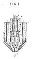
- numeral 1 designates an electrode holder having interiorly a coolant water passage 2 and brazed on a forward end thereof with an electrode 3 that is inserted and embedded therein under pressure, the electrode holder 1 and the electrode 3 constituting an electrode body 15.
- Numeral 4 denotes a nozzle that is designed to enclose a forward end portion of the electrode body 15, that is spaced therefrom across a plasma gas passage 5, that is arranged so as to be coaxial with the electrode body 15 and that is provided with a plasma arc projecting outlet 6.
- Numeral 7 represents a shielding cap that is arranged to enclose the outer side of the nozzle 4, that is spaced therefrom across a shielding gas passage 8 and that is provided coaxially with the nozzle 4.
- the above mentioned plasma gas passage 5 is provided at an upstream portion thereof with a swirler 9 which is constructed so that its swirling passage 9a may be aligned in a plane perpendicular to the axis of the electrode holder 1 or may be configured so as to be inclined slightly towards its forward end side, thereby permitting an intensive swirling or vortex flow of a gas passing through the swirling passage 9a to be generated therein.
- a swirler 9 which is constructed so that its swirling passage 9a may be aligned in a plane perpendicular to the axis of the electrode holder 1 or may be configured so as to be inclined slightly towards its forward end side, thereby permitting an intensive swirling or vortex flow of a gas passing through the swirling passage 9a to be generated therein.
- the above mentioned shielding gas passage 8 is also interiorly provided with a ring 10.
- the direction in which the gas is blown out of the ring 10 is here determined depending upon the material and the thickness of a pair of workpieces to be welded together.
- the shielding gas is to be swirled by the ring 10
- the direction in which the shielding gas is swirled is identical to the direction in which the plasma gas is swirled by the swirler 9, there will be an effect whereby the plasma arc (i. e. jet) is strongly pinched and this will be effective for cutting a workpiece, or welding together a pair of workpieces, which would require a plasma arc of high energy density.
- the swirling flow component that is possessed by the plasma arc i. e. jet
- the swirling flow component that is possessed by the plasma arc can be alleviated so as to be effective, in welding, to maintain a molten pool in a stabilized state.
- this is effective for a spot welding operation in which a large nugget is required and for a seam welding operation in which a thick bead width is necessary.
- the above mentioned electrode holder 1 is composed of a material that is high in its thermal conductivity such as copper, and is designed to be cooled by a water coolant passing through the coolant water passage 2. Further, the electrode 3 is composed of a material that is high in its melting point such as tungsten.
- the electrode 3 is of a size that is sufficient to occupy the entirety of the forward end portion of the electrode holder 1 whereas the distance s between the forward peripheral portion of the electrode 3 and the inner surface of the nozzle 4 is designed to be the shortest distance between the electrode holder 1 and the electrode portion including the electrode 3 so that when the electrode 3 is electrically energized, a pilot arc may be generated at the forward peripheral portion of the electrode 3.
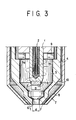
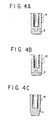
- the electrode holder 1 and the electrode 3 mentioned above may be constructed and coupled together as shown in Fig. 3 so that the entirety of the electrode 3 may be embedded in the forward end portion of the electrode holder 1, it should be noted that the electrode 3 may be fittedly attached to the forward end surface of the electrode holder 1 as shown in Figs. 4A and 4B.
- the entire electrode body 15 may be composed of a material that is high in its melting point such as tungsten or of a mixture of the high melting point material with a substance that is low in its work function or with an oxide of this substance, and may be provided interiorly with a cooling space (e. g. a space for cooling with water).
- a cooling space e. g. a space for cooling with water
- the electrode 3 that was held securely to the forward end of the electrode holder 1 had a forward end that was shaped in a planar configuration.
- the diameter D of the planar portion of of the forward end of the electrode 3 be smaller than the diameter d of the nozzle (i. e. D. ⁇ d). If the diameter D of the planar portion of the forward end of the electrode is greater than the diameter d of the nozzle, it has been found that a dual arcing may be generated at the time at which an arc is ignited. It has also been found that if the forward end of the electrode is shaped into a planar configuration, its deformation (i. e. deterioration) with the lapse of time can be reduced to a minimum.
- the electrode 3 had a planar forward end, which was then formed thereon with an edge portion 11.
- the electrode can be formed on its forward end with the edge portion 11 by boring a hole in the electrode with a drill or by milling the electrode with a milling machine.
- the electrode configuration that has an effect as described above in connection with Fig. 5B can be implemented by the formation of an arcuate hole 11a on the forward end of the electrode 3 as shown in Fig. 5C, the provision of a stepped hole 11b thereon as shown Fig. 5D, the formation of a cylindrical projection 11c on the forward end of the electrode 3 as shown in Fig. 5E, or alternatively the provision of a conical projection 11d thereon as shown in Fig. 5F.
- the edge portion of the outer hole no longer wears off, the cathodic point of the arc will come to be fixed at the edge portion of the inner hole, thereby enabling the life of the electrode to be further lengthened.
- an electrode 3' had a forward end that was contoured in a spherical configuration.
- the forward end of the electrode 3' is contoured in a spherical configuration, it has been found that there can be generated a main arc which is quickly turned from a pilot arc that has been generated on the spherical electrode surface and then can smoothly be shifted to the spherical end point of the electrode.
- This phenomenon that is effected without any difficulty, even with a plasma gas which is in a relatively weak swirling or vortex flow, has been found to be highly effective when a pair of workpieces need to be welded together with a plasma gas flow that is reduced in its flow rate.
- the electrode 3' had its forward end that was contoured in a spherical electrode configuration and was formed thereon with an edge portion 11'.
- the electrode configuration that has an effect as described above in connection with Fig. 6B can be implemented by the formation of an arcuate hole 11a' on the forward end of the electrode 3' as shown in Fig. 6C, the provision of a cylindrical projection 11b' on the forward end of the electrode 3' as shown in Fig. 6D, or alternatively the provision of a conical projection 11c' thereon as shown in Fig. 6E.
- the electrode 3 may be used that is composed of, other than any of the materials mentioned above, tungsten with 2 % of lanthana.
- a whole surface of the electrode holder 1 which had an electrode 12 embedded in a surface zone thereof, that is, the electrode body 15 was coated with a coating layer 13 of a material that is high in its melting point, or a mixture of the high melting point material with a substance that is low in its work function or with an oxide of that substance, by the flame spraying or the evaporation thereof.
- a material that is high in its melting point (such as tungsten with 2 % of thoria) which is like the material of the electrode 12, can be coated over the entire forward end surface, including the surface of the electrode 12, of the electrode holder 1. It has been found that this will allow the electrode holder 1 to be prevented from being deteriorated by an evaporation and so forth, and will at the same time prevent the surface of the electrode holder 1 from deteriorating into a matted and embossed surface and prevent a failure in the ignition arising from bridging between the electrode 12 and the nozzle 4.
- a silver plating 14 may be applied to the surfaces of the electrode holder 1.
- the electrode 1 can be matted and embossed exclusively on a forward end portion thereof.
- the reasqn for this is that while an arc has a property that it will be stabilized if its cathodic point lies on an oxide, owing to the fact that silver reduced the oxide at a high temperature the cathodic point will be hard to exist on the silver plated electrode holder and, as a result, will tend to be displaced towards the electrode 12, thereby causing the arc to be concentrated on a forward end portion of the electrode, thus preventing the electrode holder 1 from being matted and embossed on a surface thereof.
- the material that is high in its thermal conductivity which is used to constitute the electrode holder and the nozzle in each of the above mentioned examples may, other than copper, include silver, gold, aluminum and an alloy of each of these metals.
- the material that is high in its melting point which is used to constitute the electrode may, other than tungsten, include tantalum, molybdeum, osmium, rhenium, lutetium, iridium and an alloy of each of these metals.
- the substance that is low in its work function which is to be added to a high melting point material as mentioned above may include thorium, barium, cesium, cerium, lanthanum, yttrium and zirconium.
- Example 2 An endurance experiment for Example 2 shown in connection with Fig. 5B, among the various Examples mentioned above, was conducted and its results are set forth below.
- Target Value 50000 times which are the arc ignition number that represents the electrode life in a resistance spot welding machine.
Landscapes
- Physics & Mathematics (AREA)
- Engineering & Computer Science (AREA)
- Plasma & Fusion (AREA)
- Spectroscopy & Molecular Physics (AREA)
- Geometry (AREA)
- Plasma Technology (AREA)
- Arc Welding In General (AREA)
Description
| Nozzle Diameter | 2.4 mm |
| Welding Current | 90 A |
| | 7 seconds |
| Plasma Gas | Ar; 3.0x10⁻⁵ m3/s (1.8 L/min) |
| Shielding Gas | Ar + 7%H2 ; 1.2x10⁻⁴ m3/s (7 L/min) |
| Standoff Distance | 4.5 mm |
| Crater Treatment (After Heat Treatment) | None |
| Torch Attitude | Downwards | | 4 mm |
| Anode | Water Cooled Cu Target | Welding Current | 90 A |
| Main Current On Time | 0.5 sec | ||
| Current Off Time | 0.5 sec | ||
| Plasma Gas | Ar + 7%H2 7.5 x 10⁻⁵ m3/s (4.5 L/min) | Standoff Distance | 6.5 mm |
| Assist. Gas | Ar + 7%H2 1.7 x 10⁻⁴ m3/s (10 L/min) | Pilot Current | 15 A |
| Torch Att. | Downwards | N. D. | 4 mm | |
| Anode (Welding Material) | · SPH (SS400) · t2.3(Torch Side; Upper Side) + t2.3 (Lower Side) · Gap : 0 mm | W. C. | 90 A | |
| M. C. D. | 6.0 seconds | |||
| Post Heat | C. Off | 2.5 sec. | ||
| C. | 90 A; | |||
| On | 0.1 sec. | |||
| Plasma Gas | Ar + 7%H2 7.5 x 10⁻⁵ m3/s (4.5 L/min) | Standoff Distance | 6.5 mm | |
| Assist.Gas | Ar + 7%H2 1.7 x 10⁻⁴ m3/s (10 L/min) | Pilot C. | 15 A | |
| Note that Att. : Attitude; | ||||
| N. D. : Nozzle Diameter; | ||||
| W. C. : Welding Current; | ||||
| M. C. D. : Main Current Duration; and | ||||
| C. : Electric Current |
Claims (14)
- A plasma torch of plasma gas swirling flow type in which there are provided an electrode body (15;1,3) having a forward end thereof and a nozzle (4) that is arranged to enclose said forward end portion of the electrode body and that is spaced therefrom across a plasma gas flow passage (5), said electrode body (15;1,3) comprising an electrode holder (1) which is composed of a material that is high in its thermal conductivity and an electrode (3) which is securely held to or fitted to said forward end position of the electrode body,
characterized in that
said electrode (3) has the smallest distance to the nozzle (4) across said plasma gas flow passage (5) and is composed of either a material that is high in its melting point or a mixture of said high melting point material with either a substance that is low in its work function or an oxide of said substance. - A plasma torch as set forth in claim 1, characterized in that said electrode body (15;1,3,12) is coated on a surface thereof with either of said high melting point material or said mixture of the high melting point material with either of said substance that is low in its work function or said oxide of the substance, by flame spraying or evaporation thereof.
- A plasma torch as set forth in claim 1, characterized in that said electrode holder (1) is coated on a surface thereof with a silver plating.
- A plasma torch as set forth in any one of claims 1 to 3, characterized in that said electrode (3, 12) is formed with a forward end portion thereof that is in a planar configuration.
- Plasma torch according to claim 4,
characterized in that
a diameter (D) of the planar part of the forward end portion of the electrode (3) is not greater than a diameter (d) of a plasma arc projection outlet (6) of said nozzle (4). - A plasma torch as set forth in any one of claims 1 to 3, characterized in that said electrode (3) is formed with a forward end portion thereof that is in a spherical configuration.
- A plasma torch as set forth in any one of claims 1 to 3, characterized in that said electrode (3) is formed on a forward end thereof with either of a recess (11,11a,11b,11',11'a) or a projection (11c,11d,11b',11c').
- A plasma torch as set forth in any one of claims 1 to 7, characterized in that there is provided a shielding cap (7) which is constructed to enclose said nozzle (4) and which is spaced therefrom across a shielding gas passage (8); and that there is provided a ring (10) in said shielding gas passage for swirling a shielding gas therein.
- A plasma torch as set forth in claim 8, characterized in that said shielding gas is swirled in a direction that is identical to a direction in which said plasma gas is swirled.
- A plasma torch as set forth in claim 8, characterized in that said shielding gas is swirled in a direction that is opposite to a direction in which said plasma gas is swirled.
- A use of the plasma torch set forth in any one of the preceding claims for processing a workpiece body.
- A product that is made by the use set forth in claim 11.
- A machine or equipment incorporating a product as set forth in claim 12.
- An assembly of components including a product as set forth in claim 12.
Applications Claiming Priority (3)
| Application Number | Priority Date | Filing Date | Title |
|---|---|---|---|
| JP5274310A JPH07130490A (en) | 1993-11-02 | 1993-11-02 | Plasma torch |
| JP274310/93 | 1993-11-02 | ||
| PCT/JP1994/001854 WO1995012965A1 (en) | 1993-11-02 | 1994-11-02 | Plasma torch |
Publications (3)
| Publication Number | Publication Date |
|---|---|
| EP0727922A1 EP0727922A1 (en) | 1996-08-21 |
| EP0727922A4 EP0727922A4 (en) | 1996-10-30 |
| EP0727922B1 true EP0727922B1 (en) | 1999-06-02 |
Family
ID=17539869
Family Applications (1)
| Application Number | Title | Priority Date | Filing Date |
|---|---|---|---|
| EP94931677A Expired - Lifetime EP0727922B1 (en) | 1993-11-02 | 1994-11-02 | Plasma torch |
Country Status (8)
| Country | Link |
|---|---|
| US (1) | US5726414A (en) |
| EP (1) | EP0727922B1 (en) |
| JP (1) | JPH07130490A (en) |
| KR (1) | KR960706283A (en) |
| CN (1) | CN1134217A (en) |
| CA (1) | CA2174317C (en) |
| DE (1) | DE69418894T2 (en) |
| WO (1) | WO1995012965A1 (en) |
Cited By (1)
| Publication number | Priority date | Publication date | Assignee | Title |
|---|---|---|---|---|
| US12701648B1 (en) | 2020-08-05 | 2026-08-04 | Kjellberg-Stiftung | Electrode for a plasma cutting torch, assembly having said electrode, plasma cutting torch having said electrode, and method for plasma cutting |
Families Citing this family (55)
| Publication number | Priority date | Publication date | Assignee | Title |
|---|---|---|---|---|
| US5951888A (en) * | 1998-07-09 | 1999-09-14 | The Esab Group, Inc. | Plasma electrode with arc-starting grooves |
| US6020572A (en) * | 1998-08-12 | 2000-02-01 | The Esab Group, Inc. | Electrode for plasma arc torch and method of making same |
| US6207923B1 (en) * | 1998-11-05 | 2001-03-27 | Hypertherm, Inc. | Plasma arc torch tip providing a substantially columnar shield flow |
| TW469757B (en) * | 1999-12-13 | 2001-12-21 | Nippon Steel Corp | A transferred plasma heating anode |
| AT408079B (en) * | 2000-01-11 | 2001-08-27 | Hoffmann Hans | WELDING TORCH AND ELECTRIC NOZZLE |
| JP2001205441A (en) * | 2000-01-18 | 2001-07-31 | Ramu Technologies:Kk | Arc welding method and torch for arc welding |
| US6841754B2 (en) * | 2001-03-09 | 2005-01-11 | Hypertherm, Inc. | Composite electrode for a plasma arc torch |
| DE10210421B4 (en) * | 2002-03-06 | 2007-11-22 | Fraunhofer-Gesellschaft zur Förderung der angewandten Forschung e.V. | Electrode element for plasma torches and method for the production |
| JP2006114450A (en) * | 2004-10-18 | 2006-04-27 | Yutaka Electronics Industry Co Ltd | Plasma generating device |
| US20060089861A1 (en) * | 2004-10-22 | 2006-04-27 | Oracle International Corporation | Survey based risk assessment for processes, entities and enterprise |
| WO2006048649A1 (en) * | 2004-11-05 | 2006-05-11 | Dow Corning Ireland Limited | Plasma system |
| WO2006059808A1 (en) * | 2004-12-03 | 2006-06-08 | Kabushiki Kaisha Toyota Jidoshokki | Submerged plasma-use electrode, submerged plasma generating device and submerged plasma generating method |
| KR101371979B1 (en) * | 2005-04-19 | 2014-03-07 | 하이퍼썸, 인크. | Plasma arc torch providing angular shield flow injection |
| SE529056C2 (en) * | 2005-07-08 | 2007-04-17 | Plasma Surgical Invest Ltd | Plasma generating device, plasma surgical device and use of a plasma surgical device |
| JP2007066677A (en) * | 2005-08-31 | 2007-03-15 | Koike Sanso Kogyo Co Ltd | Electrode for plasma torch |
| US7575182B2 (en) * | 2006-05-18 | 2009-08-18 | R.P. Scherer Technologies, Inc. | Nozzle structure |
| JP5275342B2 (en) | 2007-05-11 | 2013-08-28 | エスディーシー マテリアルズ インコーポレイテッド | Particle production system and particle production method |
| US20090039062A1 (en) * | 2007-08-06 | 2009-02-12 | General Electric Company | Torch brazing process and apparatus therefor |
| US8507401B1 (en) | 2007-10-15 | 2013-08-13 | SDCmaterials, Inc. | Method and system for forming plug and play metal catalysts |
| CN102596478B (en) * | 2009-11-04 | 2014-12-17 | 株式会社安川电机 | Non-consumable electrode type arc welding apparatus |
| US9126191B2 (en) | 2009-12-15 | 2015-09-08 | SDCmaterials, Inc. | Advanced catalysts for automotive applications |
| US9149797B2 (en) | 2009-12-15 | 2015-10-06 | SDCmaterials, Inc. | Catalyst production method and system |
| US9420680B2 (en) * | 2009-12-15 | 2016-08-16 | Danmarks Tekniske Universitet | Apparatus and a method and a system for treating a surface with at least one gliding arc source |
| US8557727B2 (en) | 2009-12-15 | 2013-10-15 | SDCmaterials, Inc. | Method of forming a catalyst with inhibited mobility of nano-active material |
| US8470112B1 (en) | 2009-12-15 | 2013-06-25 | SDCmaterials, Inc. | Workflow for novel composite materials |
| US9119309B1 (en) | 2009-12-15 | 2015-08-25 | SDCmaterials, Inc. | In situ oxide removal, dispersal and drying |
| US8652992B2 (en) * | 2009-12-15 | 2014-02-18 | SDCmaterials, Inc. | Pinning and affixing nano-active material |
| US8545652B1 (en) | 2009-12-15 | 2013-10-01 | SDCmaterials, Inc. | Impact resistant material |
| WO2011084534A1 (en) * | 2009-12-15 | 2011-07-14 | Sdcmaterials Llc | Advanced catalysts for fine chemical and pharmaceutical applications |
| US8803025B2 (en) | 2009-12-15 | 2014-08-12 | SDCmaterials, Inc. | Non-plugging D.C. plasma gun |
| CN101885117B (en) * | 2010-06-27 | 2012-03-07 | 珠海精易焊接设备有限公司 | Spot welding cutter for spot-welding machine and production method thereof |
| US8362387B2 (en) * | 2010-12-03 | 2013-01-29 | Kaliburn, Inc. | Electrode for plasma arc torch and related plasma arc torch |
| US8669202B2 (en) | 2011-02-23 | 2014-03-11 | SDCmaterials, Inc. | Wet chemical and plasma methods of forming stable PtPd catalysts |
| HK1199222A1 (en) | 2011-08-19 | 2015-06-26 | SDCmaterials, Inc. | Coated substrates for use in catalysis and catalytic converters and methods of coating substrates with washcoat compositions |
| US9150949B2 (en) | 2012-03-08 | 2015-10-06 | Vladmir E. BELASHCHENKO | Plasma systems and methods including high enthalpy and high stability plasmas |
| US11783138B2 (en) | 2012-04-04 | 2023-10-10 | Hypertherm, Inc. | Configuring signal devices in thermal processing systems |
| PL2667689T3 (en) | 2012-05-24 | 2019-04-30 | Kjellberg Stiftung | Electrode for plasma cutting torch and use of same |
| US9156025B2 (en) | 2012-11-21 | 2015-10-13 | SDCmaterials, Inc. | Three-way catalytic converter using nanoparticles |
| US9511352B2 (en) | 2012-11-21 | 2016-12-06 | SDCmaterials, Inc. | Three-way catalytic converter using nanoparticles |
| CN105592921A (en) | 2013-07-25 | 2016-05-18 | Sdc材料公司 | Washcoats and coated substrates for catalytic converters and method for manufacturing and using same |
| CN103533737A (en) * | 2013-10-21 | 2014-01-22 | 芜湖鼎恒材料技术有限公司 | Cathode head of plasma spray gun |
| CA2926135A1 (en) | 2013-10-22 | 2015-04-30 | SDCmaterials, Inc. | Compositions of lean nox trap |
| CN106061600A (en) | 2013-10-22 | 2016-10-26 | Sdc材料公司 | Catalyst design for heavy-duty diesel combustion engines |
| US12275082B2 (en) | 2013-11-13 | 2025-04-15 | Hypertherm, Inc. | Consumable cartridge for a plasma arc cutting system |
| US11684995B2 (en) | 2013-11-13 | 2023-06-27 | Hypertherm, Inc. | Cost effective cartridge for a plasma arc torch |
| US12521905B2 (en) | 2014-03-07 | 2026-01-13 | Hypertherm, Inc. | Liquid pressurization pump and systems with data storage |
| US9687811B2 (en) | 2014-03-21 | 2017-06-27 | SDCmaterials, Inc. | Compositions for passive NOx adsorption (PNA) systems and methods of making and using same |
| US9572242B2 (en) * | 2014-05-19 | 2017-02-14 | Lincoln Global, Inc. | Air cooled plasma torch and components thereof |
| DE202015002334U1 (en) * | 2014-10-14 | 2015-06-17 | Hypertherm, Inc. | Highly accessible consumables for a plasma arc cutting system |
| AU2018217728B2 (en) * | 2017-02-09 | 2022-04-14 | Hypertherm, Inc. | Swirl ring and contact element for a plasma arc torch cartridge |
| CN107262886A (en) * | 2017-06-01 | 2017-10-20 | 安徽吉乃尔电器科技有限公司 | A kind of plasma cutter of tin plate |
| JP7478733B2 (en) * | 2018-11-30 | 2024-05-07 | エリコン メテコ(ユーエス)インコーポレイテッド | Plasma gun electrodes |
| CN210373578U (en) * | 2019-07-26 | 2020-04-21 | 深圳驭龙电焰科技有限公司 | Ion needle and furnace end |
| US20230363079A1 (en) * | 2020-03-06 | 2023-11-09 | Praxair S.T. Technology, Inc. | Modified cathode device and holder assembly for plasma arc spray gun |
| BR102020017034A2 (en) * | 2020-08-20 | 2022-03-03 | Petróleo Brasileiro S.A. - Petrobras | Atmospheric plasma reactor for large-scale production of carbon nanotubes and amorphous carbon |
Family Cites Families (22)
| Publication number | Priority date | Publication date | Assignee | Title |
|---|---|---|---|---|
| JPS50151737A (en) * | 1974-05-08 | 1975-12-05 | ||
| CH607540A5 (en) * | 1976-02-16 | 1978-12-29 | Niklaus Mueller | |
| US4133987A (en) * | 1977-12-07 | 1979-01-09 | Institut Elektrosvarki Imeni E.O. Patona Adakemii Nauk | Electrode assembly for plasma arc torches |
| SU1063558A1 (en) * | 1982-03-03 | 1983-12-30 | Специальный Проектно-Конструкторский Институт Министерства Тракторного И Сельскохозяйственного Машиностроения | Torch for gas-shielded arc welding |
| US4521666A (en) * | 1982-12-23 | 1985-06-04 | Union Carbide Corporation | Plasma arc torch |
| SE452862B (en) * | 1985-06-05 | 1987-12-21 | Aga Ab | LIGHT BAGS LEAD |
| JPS63135719U (en) * | 1987-02-26 | 1988-09-06 | ||
| US4764656A (en) * | 1987-05-15 | 1988-08-16 | Browning James A | Transferred-arc plasma apparatus and process with gas heating in excess of anode heating at the workpiece |
| JPH049097Y2 (en) * | 1987-05-30 | 1992-03-06 | ||
| US4928027A (en) * | 1987-08-20 | 1990-05-22 | The United States Of America As Represented By The Administrator Of The National Aeronautics And Space Administration | High temperature refractory member with radiation emissive overcoat |
| JPH01135174A (en) * | 1987-11-20 | 1989-05-26 | Matsushita Electric Ind Co Ltd | Automatic answering telephone set |
| US4843282A (en) * | 1988-02-16 | 1989-06-27 | Gte Products Corporation | Glow discharge starter containing silver |
| US4919191A (en) * | 1988-05-17 | 1990-04-24 | Jeneric/Pentron Incorporated | Molten-metal forming method and apparatus which are bottom-loading, bottom-pouring and bottom-unloading |
| JPH01299777A (en) * | 1988-05-24 | 1989-12-04 | Komatsu Ltd | Structure of plasma torch |
| US5120930A (en) * | 1988-06-07 | 1992-06-09 | Hypertherm, Inc. | Plasma arc torch with improved nozzle shield and step flow |
| US5023425A (en) * | 1990-01-17 | 1991-06-11 | Esab Welding Products, Inc. | Electrode for plasma arc torch and method of fabricating same |
| US5013885A (en) * | 1990-02-28 | 1991-05-07 | Esab Welding Products, Inc. | Plasma arc torch having extended nozzle of substantially hourglass |
| US5105061A (en) * | 1991-02-15 | 1992-04-14 | The Lincoln Electric Company | Vented electrode for a plasma torch |
| US5239162A (en) * | 1992-01-30 | 1993-08-24 | Retech, Inc. | Arc plasma torch having tapered-bore electrode |
| JPH05226096A (en) * | 1992-02-17 | 1993-09-03 | Fujitsu Ltd | Plasma torch and plasma jet generation method |
| JP2591371Y2 (en) * | 1993-02-24 | 1999-03-03 | 株式会社小松製作所 | Plasma arc torch |
| US5416296A (en) * | 1994-03-11 | 1995-05-16 | American Torch Tip Company | Electrode for plasma arc torch |
-
1993
- 1993-11-02 JP JP5274310A patent/JPH07130490A/en active Pending
-
1994
- 1994-11-02 WO PCT/JP1994/001854 patent/WO1995012965A1/en not_active Ceased
- 1994-11-02 CN CN94193999A patent/CN1134217A/en active Pending
- 1994-11-02 DE DE69418894T patent/DE69418894T2/en not_active Expired - Fee Related
- 1994-11-02 CA CA002174317A patent/CA2174317C/en not_active Expired - Fee Related
- 1994-11-02 US US08/628,666 patent/US5726414A/en not_active Expired - Fee Related
- 1994-11-02 EP EP94931677A patent/EP0727922B1/en not_active Expired - Lifetime
-
1996
- 1996-04-30 KR KR1019960702352A patent/KR960706283A/en not_active Ceased
Cited By (1)
| Publication number | Priority date | Publication date | Assignee | Title |
|---|---|---|---|---|
| US12701648B1 (en) | 2020-08-05 | 2026-08-04 | Kjellberg-Stiftung | Electrode for a plasma cutting torch, assembly having said electrode, plasma cutting torch having said electrode, and method for plasma cutting |
Also Published As
| Publication number | Publication date |
|---|---|
| JPH07130490A (en) | 1995-05-19 |
| EP0727922A4 (en) | 1996-10-30 |
| DE69418894D1 (en) | 1999-07-08 |
| EP0727922A1 (en) | 1996-08-21 |
| CN1134217A (en) | 1996-10-23 |
| WO1995012965A1 (en) | 1995-05-11 |
| KR960706283A (en) | 1996-11-08 |
| US5726414A (en) | 1998-03-10 |
| CA2174317C (en) | 2000-01-11 |
| DE69418894T2 (en) | 1999-10-21 |
Similar Documents
| Publication | Publication Date | Title |
|---|---|---|
| US5726414A (en) | Plasma torch with swirling gas flow in a shielding gas passage | |
| US5756959A (en) | Coolant tube for use in a liquid-cooled electrode disposed in a plasma arc torch | |
| US7375302B2 (en) | Plasma arc torch having an electrode with internal passages | |
| US8680425B2 (en) | Plasma arc torch having an electrode with internal passages | |
| US3575568A (en) | Arc torch | |
| US3198932A (en) | Arc electrode | |
| US7145099B2 (en) | Tip gas distributor | |
| US4059743A (en) | Plasma arc cutting torch | |
| US3204076A (en) | Electric arc torch | |
| US20110240609A1 (en) | Electrode for a Plasma Torch | |
| US6191381B1 (en) | Tapered electrode for plasma arc cutting torches | |
| US6963045B2 (en) | Plasma arc cutting torch nozzle | |
| JPH03151169A (en) | Electrode for plasma operation torch and torch corresponding thereto | |
| US6096992A (en) | Low current water injection nozzle and associated method | |
| CA1067584A (en) | Method and torch for sustaining multiple coaxial arcs | |
| US3614376A (en) | Plasma torch | |
| JPH0963790A (en) | Plasma torch nozzle | |
| JP6578078B1 (en) | TIG welding torch | |
| US5266776A (en) | Plasma arc cutting and welding tip | |
| US6137079A (en) | TIG welding torch permitting improving striking the welding arc | |
| JP6913715B2 (en) | TIG welding method | |
| JP6526885B1 (en) | TIG welding torch | |
| JPH0785992A (en) | Multi-electrode plasma jet torch | |
| JPH0544797B2 (en) | ||
| RU2811984C1 (en) | Quick wearing part for arc torch, plasma torch or plasma cutting torch, and also arc torch, plasma torch or plasma cutting torch with the specified part and method of plasma cutting, as well as method of manufacturing electrode for arc torch, plasma torch or plasma cutting torch |
Legal Events
| Date | Code | Title | Description |
|---|---|---|---|
| PUAI | Public reference made under article 153(3) epc to a published international application that has entered the european phase |
Free format text: ORIGINAL CODE: 0009012 |
|
| 17P | Request for examination filed |
Effective date: 19960429 |
|
| AK | Designated contracting states |
Kind code of ref document: A1 Designated state(s): DE FR GB IT SE |
|
| A4 | Supplementary search report drawn up and despatched | ||
| AK | Designated contracting states |
Kind code of ref document: A4 Designated state(s): DE FR GB IT SE |
|
| 17Q | First examination report despatched |
Effective date: 19970924 |
|
| GRAG | Despatch of communication of intention to grant |
Free format text: ORIGINAL CODE: EPIDOS AGRA |
|
| GRAG | Despatch of communication of intention to grant |
Free format text: ORIGINAL CODE: EPIDOS AGRA |
|
| GRAH | Despatch of communication of intention to grant a patent |
Free format text: ORIGINAL CODE: EPIDOS IGRA |
|
| GRAH | Despatch of communication of intention to grant a patent |
Free format text: ORIGINAL CODE: EPIDOS IGRA |
|
| GRAA | (expected) grant |
Free format text: ORIGINAL CODE: 0009210 |
|
| AK | Designated contracting states |
Kind code of ref document: B1 Designated state(s): DE FR GB IT SE |
|
| PG25 | Lapsed in a contracting state [announced via postgrant information from national office to epo] |
Ref country code: SE Free format text: THE PATENT HAS BEEN ANNULLED BY A DECISION OF A NATIONAL AUTHORITY Effective date: 19990602 Ref country code: IT Free format text: LAPSE BECAUSE OF FAILURE TO SUBMIT A TRANSLATION OF THE DESCRIPTION OR TO PAY THE FEE WITHIN THE PRESCRIBED TIME-LIMIT;WARNING: LAPSES OF ITALIAN PATENTS WITH EFFECTIVE DATE BEFORE 2007 MAY HAVE OCCURRED AT ANY TIME BEFORE 2007. THE CORRECT EFFECTIVE DATE MAY BE DIFFERENT FROM THE ONE RECORDED. Effective date: 19990602 Ref country code: FR Free format text: LAPSE BECAUSE OF FAILURE TO SUBMIT A TRANSLATION OF THE DESCRIPTION OR TO PAY THE FEE WITHIN THE PRESCRIBED TIME-LIMIT Effective date: 19990602 |
|
| REF | Corresponds to: |
Ref document number: 69418894 Country of ref document: DE Date of ref document: 19990708 |
|
| EN | Fr: translation not filed | ||
| PG25 | Lapsed in a contracting state [announced via postgrant information from national office to epo] |
Ref country code: GB Free format text: LAPSE BECAUSE OF NON-PAYMENT OF DUE FEES Effective date: 19991102 |
|
| PGFP | Annual fee paid to national office [announced via postgrant information from national office to epo] |
Ref country code: DE Payment date: 19991108 Year of fee payment: 6 |
|
| PLBQ | Unpublished change to opponent data |
Free format text: ORIGINAL CODE: EPIDOS OPPO |
|
| PLBI | Opposition filed |
Free format text: ORIGINAL CODE: 0009260 |
|
| PLBF | Reply of patent proprietor to notice(s) of opposition |
Free format text: ORIGINAL CODE: EPIDOS OBSO |
|
| 26 | Opposition filed |
Opponent name: L'AIR LIQUIDE, S.A. POUR L'ETUDE ET L'EXPLOITATION Effective date: 20000221 |
|
| GBPC | Gb: european patent ceased through non-payment of renewal fee |
Effective date: 19991102 |
|
| PLBF | Reply of patent proprietor to notice(s) of opposition |
Free format text: ORIGINAL CODE: EPIDOS OBSO |
|
| PG25 | Lapsed in a contracting state [announced via postgrant information from national office to epo] |
Ref country code: DE Free format text: LAPSE BECAUSE OF NON-PAYMENT OF DUE FEES Effective date: 20010801 |
|
| PLBQ | Unpublished change to opponent data |
Free format text: ORIGINAL CODE: EPIDOS OPPO |
|
| PLAB | Opposition data, opponent's data or that of the opponent's representative modified |
Free format text: ORIGINAL CODE: 0009299OPPO |
|
| R26 | Opposition filed (corrected) |
Opponent name: L'AIR LIQUIDE, S.A.POUR L'ETUDE ET L'EXPLOITATIOND Effective date: 20000221 |
|
| PLBD | Termination of opposition procedure: decision despatched |
Free format text: ORIGINAL CODE: EPIDOSNOPC1 |
|
| PLBM | Termination of opposition procedure: date of legal effect published |
Free format text: ORIGINAL CODE: 0009276 |
|
| STAA | Information on the status of an ep patent application or granted ep patent |
Free format text: STATUS: OPPOSITION PROCEDURE CLOSED |
|
| 27C | Opposition proceedings terminated |
Effective date: 20060805 |