EP0727563B1 - Amortisseur des vibrations pour aubes des turbines - Google Patents
Amortisseur des vibrations pour aubes des turbines Download PDFInfo
- Publication number
- EP0727563B1 EP0727563B1 EP96301044A EP96301044A EP0727563B1 EP 0727563 B1 EP0727563 B1 EP 0727563B1 EP 96301044 A EP96301044 A EP 96301044A EP 96301044 A EP96301044 A EP 96301044A EP 0727563 B1 EP0727563 B1 EP 0727563B1
- Authority
- EP
- European Patent Office
- Prior art keywords
- damper
- blade
- airfoil
- rotor blade
- Prior art date
- Legal status (The legal status is an assumption and is not a legal conclusion. Google has not performed a legal analysis and makes no representation as to the accuracy of the status listed.)
- Expired - Lifetime
Links
Images
Classifications
-
- F—MECHANICAL ENGINEERING; LIGHTING; HEATING; WEAPONS; BLASTING
- F01—MACHINES OR ENGINES IN GENERAL; ENGINE PLANTS IN GENERAL; STEAM ENGINES
- F01D—NON-POSITIVE DISPLACEMENT MACHINES OR ENGINES, e.g. STEAM TURBINES
- F01D5/00—Blades; Blade-carrying members; Heating, heat-insulating, cooling or antivibration means on the blades or the members
- F01D5/12—Blades
- F01D5/14—Form or construction
- F01D5/16—Form or construction for counteracting blade vibration
-
- Y—GENERAL TAGGING OF NEW TECHNOLOGICAL DEVELOPMENTS; GENERAL TAGGING OF CROSS-SECTIONAL TECHNOLOGIES SPANNING OVER SEVERAL SECTIONS OF THE IPC; TECHNICAL SUBJECTS COVERED BY FORMER USPC CROSS-REFERENCE ART COLLECTIONS [XRACs] AND DIGESTS
- Y10—TECHNICAL SUBJECTS COVERED BY FORMER USPC
- Y10S—TECHNICAL SUBJECTS COVERED BY FORMER USPC CROSS-REFERENCE ART COLLECTIONS [XRACs] AND DIGESTS
- Y10S416/00—Fluid reaction surfaces, i.e. impellers
- Y10S416/50—Vibration damping features
Definitions
- This invention applies to turbine engine rotor assemblies in general, and to apparatus for damping vibration within turbine engine rotor assemblies in particular.
- Turbine and compressor sections within an axial flow turbine engine generally include a rotor assembly comprising a rotating disk and a plurality of rotor blades circumferentially disposed around the disk.
- Each rotor blade includes a root, an airfoil, and a platform positioned in the transition area between the root and the airfoil.
- the roots of the blades are received in complementary shaped recesses within the disk.
- the platforms of the blades extend laterally outward and collectively form a flow path for fluid passing through the rotor stage.
- turbine engine rotor assemblies rotate at a variety of speeds through fluid that varies in temperature, pressure, and density.
- the blades may be excited in a number of different modes of vibration.
- Lower order modes such as the first bending mode and first torsion mode, are generally predictable enough such that a single style damper may be implemented throughout the rotor assembly. For instance, a particular style damper may be implemented against the blade platforms of adjacent blades to damp lower order vibration.
- Upstream airfoils within a multiple stage rotor assembly can create aerodynamic wakes that cause downstream airfoils to experience higher order modes of vibration such as plate deformation.
- Plate deformation predominantly in the form of chordwise bending, often manifests in upper regions of the airfoil in a non-symmetrical pattern and is accordingly difficult to predict in terms of magnitude and position.
- the present invention provides a rotor blade for a turbine engine rotor assembly, said rotor blade having an airfoil and including means for damping vibration in said airfoil, wherein said airfoil comprises a pocket formed in a chordwise surface thereof, characterised in that said vibration damping means comprises a damper and a pocket lid, said damper being received in said pocket and maintained there by the pocket lid, the pocket lid being contoured to match the curvature of the airfoil.
- said damper is biassed between an inner surface of the pocket and the pocket lid.
- the pocket lid can be attached to the airfoil by conventional attachment means such as welding. Relative movement between the pocket, pocket lid, and damper causes vibrational movement to be damped and dissipated in the form of frictional energy.
- the damper may be a sinusoidal shaped member biased between the pocket and the pocket lid.
- the pocket lid includes means for locating the damper within the pocket, which maintain the damper in a particular area of the pocket and which may prevent the damper from interfering with the attachment means used to attach the pocket lid to the pocket.
- the damper may be a plurality of strands formed in a mesh which is received within the pocket said mesh contacting said pocket lid and said inner surface of said pocket at a plurality of points, wherein vibration of said blade causes motion of said blade relative to said damper, and motion of said strands relative to one another, and therefore damping of motion between said blade and said damper due to friction between said damper and said blade, and friction between said strands.
- the invention also extends to a rotor blade assembly for a turbine engine, comprising a plurality of rotor blades as described above, and a disk, having an outer surface which includes a plurality of complementary recesses circumferentially distributed around said disk, for receiving said blades.
- a method for damping vibrations in a rotor blade of a turbine rotor assembly comprising the steps of:
- One advantage of the preferred embodiments of the present invention is that means for damping vibrations in a rotor blade is provided which minimizes air flow disturbance adjacent the rotor blade. Minimizing turbulent air flow within a rotor assembly is critical both performance-wise and to prevent undesirable forcing functions downstream and the vibrations that often accompany them.
- Another advantage of the preferred embodiments of the present invention is that the means for damping vibrations has minimal effect on the structural integrity of the rotor blade.
- a person of skill in the art will recognize that it is known to have a hollow rotor blade and damping means positioned within the hollow as disclosed for example in US 2689107.
- Hollow rotor blades are either cast hollow or are cast in halves and subsequently joined by a welding process such as inertia welding.
- One piece cast hollow blades must include an opening sufficient to accommodate the damping device. The opening and the accompanying increased volume of the hollow generally decrease the blade's stress tolerance.
- Seamed hollow blade halves allow an internal pocket to be formed without the access hole, but have the disadvantage of having a seam about the periphery of the entire blade and whatever residual weld material is extruded into the internal pocket. Both the seam and the excess weld material are stress risers that adversely affect the resistance to stress.
- the preferred embodiments of the present invention allows the blade to be formed as a single piece and only the material necessary for the pocket is subsequently removed.
- Still another advantage of the preferred embodiments of the present invention is that biasing (i.e. preloading) the damper in the pocket decreases the frictional wear on the damper.
- the prior art discloses enclosing one piece solid slugs or a plurality of shims in an internal pocket within a seamed blade.
- a disadvantage to these approaches is that the loose pieces within the pocket(s) tend to move more within the pocket(s) and therefore frictionally wear at a pace greater than that of the biased damper of the present invention.
- Still another advantage of the preferred embodiments of the present invention is that the damper is enclosed within the pocket and therefore not subject to the harsh external environment.
- the fluids drawn through the rotor assembly expose the airfoil external surfaces to foreign elements and corrosive conditions precipitated by the high temperature and composition of the fluid. It is known in the art, as disclosed in US-A-3 796 513 for example, to have a rotor blade having a lengthwise depression and a damper material disposed in the depression. Thus the outer surface of the damper is exposed to the external environment.
- the present assembly insulates the damper from these undesirable external conditions and therefore maximizes the useful life of the damper.
- Still another advantage of the preferred embodiments of the present invention is that the means for damping vibration in a rotor blade can be installed easily and in a cost-efficient manner. Joining rotor blade halves, and installing a damping means therebetween, adds significant difficulty, and therefore cost, to the manufacturing process of the rotor blades.
- Still another advantage of the preferred embodiments of the present invention is that the means for damping vibration in a rotor blade can be tailored and positioned in the blade to counteract specific vibratory conditions in particular blades.
- Cast hollow rotor blades must define the position of the damping device prior to vibration testing that particular blade.
- cast hollow blades must also include passages through the blade to the position. Consequently, the pocket geometry and/or position may not always be the optimum geometry and/or in the optimum position.
- Seamed rotor blade halves similarly may not have the optimum internal pocket geometry or position and in addition, may not have the optimum damping device since the device must be inserted before the halves are seamed.
- the preferred embodiments of the present invention permit the blade to be tested first and subsequently have a damping means properly chosen and installed if necessary. In other words, specific unsymmetrical higher order vibratory conditions can be identified and then accommodated using the present invention.
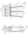
- the rotor assembly 10 includes a rotating disk 12 and a plurality of rotor blades 14 circumferentially disposed around the disk 12.
- Each rotor blade 14 includes a root 16, an airfoil 18, a platform 20 positioned in the transition area between the root 16 and the airfoil 18, and means 22 (see FIGS. 2 and 3A-3C) for damping vibrations in the blade 14.
- the roots 16 are received within complementary shaped recesses 24 in the disk 12.
- Each airfoil 18 includes a pocket 26 (see FIGS. 3A-3C) for receiving the means 22 for damping vibrations.
- the pocket 26 is disposed in a chordwise face 28 of the airfoil 18 and is defined as having sidewalls 30 and an inner surface 32.
- the means 22 for damping vibrations includes a damper 34 and a pocket lid 36.
- the damper 34 is received within the pocket 26 and maintained there by the pocket lid 36.
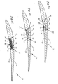
- the damper 34 comprises an element formed in a sinusoidal shape having an amplitude and a period, as is shown in FIG. 3A. Different amplitudes and periods may be implemented as is necessary to alter the amount of surface area in contact and the magnitude of the frictional contact between the damper 34 and the inner surface 32 of the pocket 26 and between the damper 34 and the pocket lid 36.
- corrugations having other than a sinusoidal shape may be used alternatively (see FIG.3B).
- the damper 34 comprises a mesh 38 of strands 39.
- the mesh strands 39 provide contact not only with the pocket 26 and the lid 36, but also between the strands 39 within the mesh 38.
- a coating 42 such as a copper alloy or a dry film lubricant, may be implemented at the friction points to promote the dissipation of energy and to minimize the wear.
- the pocket lid 36 is a metallic element having a shape complementary to the opening of the pocket 26.
- the pocket lid 36 may include means 43 for centering the damper 34.
- the means 43 for centering the damper 34 includes tabs 44 formed in, or attached to, the pocket lid 36 that maintain the damper 34 in a particular area of the pocket 26.
- each blade, or a representative sample of the total number are examined to determine the blade's vibratory characteristics.
- a number of methodologies such as impact testing, holography, and stress pattern analysis by thermal emission (SPATE), are employed to ascertain the blade's fundamental frequencies and modes of vibration.
- SPATE stress pattern analysis by thermal emission
- the methodologies are employed to determine the position and magnitude of the modes.
- the next step in the manufacturing process of the blades 14 is to establish if a damping means 22 is required in the blade 14 being evaluated. If the blade's 14 natural frequencies coincide with the potential excitation frequencies, then a damping means 22 will generally be required to minimize the stress effects on the blade 14 caused by the vibration.
- the required capacity and position of the damping means 22 are determined using the information developed in the vibration analysis of the blade 14. Specifically, the modes of vibration and the nodal lines thereof will indicate what vibratory amplitudes can be expected at what position.
- the pocket 26 geometry is chosen and located to intersect regions of higher vibratory amplitudes where the damping will be most effective, without significantly adding to the stress characteristics of the blade 14.
- the pocket sidewalls 30 define a circular shape and the inner surface 32 defines the base of the pocket 26, located in the upper regions of a chordwise surface 28 of the blade 14.
- the circular shape is advantageous for machining purposes, but other geometries may be used alternatively.
- a damper 34 is selected which will adequately damp the blade 14 vibrations within the problematic frequencies and modes determined earlier.
- the damper 34 is received within the pocket 26 and the pocket lid 36 is welded adjacent the opening of the pocket 26 thereby closing the pocket 26 and maintaining the damper 34 therein.
- the dimension between the inner surface 32 of the pocket 26 and the inner surface 46 of the pocket lid 36 is chosen to effectuate whatever preload (i.e. bias) is desired on the damper 34, if preload is used.
- preload i.e. bias
- damping will occur at least between the damper 34 and the pocket 26 via friction caused by the friction coefficients of the elements 26,34 and the centrifugal normal force exerted when the rotor assembly rotates.
- the exterior surface 48 of the lid 36 is contoured to agree with the curvature of the airfoil 18.
- the present invention provides a rotor blade for a turbine engine rotor assembly that includes means for damping higher order modes of vibration, and provides means for damping vibration in a rotor blade which minimizes disturbance of air flow adjacent the rotor blade, which does not negatively affect the structural integrity of the rotor blade, which has an increased resistance to wear, which can be installed easily and in a cost-efficient manner and which can be tailored and positioned in the blade to counteract specific vibratory conditions.
Claims (9)
- Pale de rotor (14) pour un ensemble de rotor de moteur à turbine, ladite pale de rotor ayant un plan de sustentation (18) et comprenant un moyen (34) pour amortir la vibration dans ledit plan de sustentation, dans lequel ledit plan de sustentation comporte une poche (26) formée dans une surface dans le sens de la corde de celle-ci, caractérisée en ce que ledit moyen d'amortissement de vibration comporte un amortisseur (34) et un couvercle (36) de poche, ledit amortisseur (34) étant reçu dans ladite poche (26) et y étant maintenu par le couvercle (36) de poche, le couvercle (36) de poche étant profilé pour correspondre à la courbure du plan de sustentation (18).
- Pale de rotor (14) selon la revendication 1, dans laquelle ledit amortisseur (34) est sollicité entre une surface interne (32) de la poche (26) et le couvercle (36) de la poche.
- Pale de rotor selon la revendication 1 ou 2, comprenant, en outre, une emplanture (16), pour attacher ladite pale (14) à un disque (12) de l'ensemble de rotor (10), et une plate-forme (20), s'étendant vers l'extérieur de ladite pale (14) dans une zone de transition entre ladite emplanture (16) et ledit plan de sustentation (18).
- Pale de rotor selon la revendication 1, 2 ou 3, dans laquelle ledit amortisseur (34) comprend une forme sinusoïdale, ledit amortisseur (34) venant en contact avec ledit couvercle (36) de poche et ladite surface interne (32) de ladite poche (26) en une pluralité de points, dans laquelle la vibration de ladite pale (14) amène le mouvement de ladite pale (14) par rapport audit amortisseur (34) et, en conséquence, l'amortissement dudit mouvement en raison d'un frottement entre ledit amortisseur (34) et ladite pale (14).
- Pale de rotor selon l'une quelconque des revendications précédentes, dans laquelle ledit couvercle (36) de poche comporte, en outre, un moyen (43) destiné à placer ledit amortisseur (34) au sein de ladite poche (24), ledit moyen de placement limitant le mouvement dudit amortisseur (34) dans ladite poche (26).
- Pale de rotor selon la revendication 1, 2 ou 3, dans laquelle ledit amortisseur (34) comporte une pluralité de torons (39) formés en une maille (38), ladite maille (38) contactant ledit couvercle (36) de poche et ladite surface interne (32) de ladite poche (26) en une pluralité de points, dans laquelle la vibration de ladite pale (14) amène le mouvement de ladite pale (14) par rapport audit amortisseur (34) et le mouvement desdits torons (39) les uns par rapport aux autres et, en conséquence, l'amortissement du mouvement entre ladite pale (14) et ledit amortisseur (34) en raison du frottement entre ledit amortisseur (34) et ladite pale (14) et le frottement entre lesdits torons (39).
- Ensemble de pale de rotor pour un moteur à turbine, comprenant une pluralité de pales de rotor selon l'une quelconque des revendications précédentes, et un disque (12), ayant une surface externe qui comporte une pluralité d'évidements complémentaires (24) distribués de manière circonférentielle autour dudit disque, afin de recevoir lesdites pales (14).
- Procédé d'amortissement de vibrations dans une pale de rotor d'un ensemble de rotor de turbine, comprenant les étapes consistant à :(a) fournir une pale de rotor (14) ayant un plan de sustentation (18);(b) déterminer les caractéristiques vibratoires de ladite pale de rotor (14), comprenant la détermination d'où des lignes nodales existent pour des modes d'ordre supérieur de vibration au sein dudit plan de sustentation (18), et où des régions de contrainte élevée existent au sein dudit plan de sustentation (18);(c) déterminer une géométrie optimale pour une poche (26) formée dans une surface dudit plan de sustentation, de telle sorte que ladite poche (26) n'intercepte pas lesdites lignes nodales et lesdites régions de contrainte élevée au sein dudit plan de sustentation (18) ;(d) former ladite poche (26) dans ladite surface ;(e) installer un amortisseur (34) dans ladite poche (26) et attacher un couvercle (36) de poche, ledit couvercle de poche maintenant l'amortisseur dans la poche ; et(f) profiler ledit couvercle de poche (36) si nécessaire pour adopter la courbure dudit plan de sustentation (18).
- Procédé selon la revendication 8, dans lequel la pale, l'amortisseur et la poche sont comme revendiqués dans l'une quelconque des revendications 1 à 6.
Applications Claiming Priority (2)
| Application Number | Priority Date | Filing Date | Title |
|---|---|---|---|
| US08/390,347 US5498137A (en) | 1995-02-17 | 1995-02-17 | Turbine engine rotor blade vibration damping device |
| US390347 | 1995-02-17 |
Publications (3)
| Publication Number | Publication Date |
|---|---|
| EP0727563A2 EP0727563A2 (fr) | 1996-08-21 |
| EP0727563A3 EP0727563A3 (fr) | 1998-11-04 |
| EP0727563B1 true EP0727563B1 (fr) | 2003-05-07 |
Family
ID=23542123
Family Applications (1)
| Application Number | Title | Priority Date | Filing Date |
|---|---|---|---|
| EP96301044A Expired - Lifetime EP0727563B1 (fr) | 1995-02-17 | 1996-02-15 | Amortisseur des vibrations pour aubes des turbines |
Country Status (4)
| Country | Link |
|---|---|
| US (1) | US5498137A (fr) |
| EP (1) | EP0727563B1 (fr) |
| JP (1) | JP3747387B2 (fr) |
| DE (1) | DE69627915T2 (fr) |
Families Citing this family (57)
| Publication number | Priority date | Publication date | Assignee | Title |
|---|---|---|---|---|
| US5725355A (en) * | 1996-12-10 | 1998-03-10 | General Electric Company | Adhesive bonded fan blade |
| US5931641A (en) * | 1997-04-25 | 1999-08-03 | General Electric Company | Steam turbine blade having areas of different densities |
| US6039542A (en) * | 1997-12-24 | 2000-03-21 | General Electric Company | Panel damped hybrid blade |
| US6155789A (en) * | 1999-04-06 | 2000-12-05 | General Electric Company | Gas turbine engine airfoil damper and method for production |
| DE19956444B4 (de) * | 1999-11-24 | 2004-08-26 | Mtu Aero Engines Gmbh | Verfahren zur Herstellung eines Leichtbauteils in Verbundbauweise |
| WO2001049975A1 (fr) * | 2000-01-06 | 2001-07-12 | Damping Technologies, Inc. | Amortisseur pour moteur a turbine |
| US6827551B1 (en) | 2000-02-01 | 2004-12-07 | The United States Of America As Represented By The Administrator Of The National Aeronautics And Space Administration | Self-tuning impact damper for rotating blades |
| DE10016912C1 (de) * | 2000-04-05 | 2001-12-13 | Aerodyn Eng Gmbh | Turmeigenfrequenzabhängige Betriebsführung von Offshore-Windenergieanlagen |
| DE10138250B4 (de) * | 2001-02-23 | 2008-11-20 | Oliver Dr. Romberg | Tragendes Bauteil in Sandwichbauweise |
| US6607359B2 (en) | 2001-03-02 | 2003-08-19 | Hood Technology Corporation | Apparatus for passive damping of flexural blade vibration in turbo-machinery |
| US6471484B1 (en) * | 2001-04-27 | 2002-10-29 | General Electric Company | Methods and apparatus for damping rotor assembly vibrations |
| US6752594B2 (en) | 2002-02-07 | 2004-06-22 | The Boeing Company | Split blade frictional damper |
| US6699015B2 (en) * | 2002-02-19 | 2004-03-02 | The Boeing Company | Blades having coolant channels lined with a shape memory alloy and an associated fabrication method |
| US6676380B2 (en) | 2002-04-11 | 2004-01-13 | The Boeing Company | Turbine blade assembly with pin dampers |
| US6685435B2 (en) | 2002-04-26 | 2004-02-03 | The Boeing Company | Turbine blade assembly with stranded wire cable dampers |
| US6796408B2 (en) * | 2002-09-13 | 2004-09-28 | The Boeing Company | Method for vibration damping using superelastic alloys |
| US7334998B2 (en) * | 2003-12-08 | 2008-02-26 | The United States Of America As Represented By The Administrator Of The National Aeronautics And Space Administration | Low-noise fan exit guide vanes |
| US7008179B2 (en) * | 2003-12-16 | 2006-03-07 | General Electric Co. | Turbine blade frequency tuned pin bank |
| GB0406444D0 (en) | 2004-03-23 | 2004-04-28 | Rolls Royce Plc | An article having a vibration damping coating and a method of applying a vibration damping coating to an article |
| US20080124480A1 (en) * | 2004-09-03 | 2008-05-29 | Mo-How Herman Shen | Free layer blade damper by magneto-mechanical materials |
| US20120135272A1 (en) | 2004-09-03 | 2012-05-31 | Mo-How Herman Shen | Method for applying a low residual stress damping coating |
| US7806410B2 (en) | 2007-02-20 | 2010-10-05 | United Technologies Corporation | Damping device for a stationary labyrinth seal |
| US7607287B2 (en) * | 2007-05-29 | 2009-10-27 | United Technologies Corporation | Airfoil acoustic impedance control |
| US20090081032A1 (en) * | 2007-09-20 | 2009-03-26 | General Electric Company | Composite airfoil |
| US8267662B2 (en) * | 2007-12-13 | 2012-09-18 | General Electric Company | Monolithic and bi-metallic turbine blade dampers and method of manufacture |
| US20090155082A1 (en) * | 2007-12-18 | 2009-06-18 | Loc Duong | Method to maximize resonance-free running range for a turbine blade |
| US8883261B2 (en) * | 2007-12-21 | 2014-11-11 | United Technologies Corporation | Artifacts, method of creating such artifacts and methods of using such artifacts |
| JP4995141B2 (ja) * | 2008-05-08 | 2012-08-08 | 三菱重工業株式会社 | タービン用翼構造 |
| US8075274B2 (en) * | 2009-05-13 | 2011-12-13 | Hamilton Sundstrand Corporation | Reinforced composite fan blade |
| US7955054B2 (en) * | 2009-09-21 | 2011-06-07 | Pratt & Whitney Rocketdyne, Inc. | Internally damped blade |
| JP5660883B2 (ja) * | 2010-12-22 | 2015-01-28 | 三菱日立パワーシステムズ株式会社 | 蒸気タービンの静翼、蒸気タービン |
| US20120237351A1 (en) * | 2011-03-17 | 2012-09-20 | Weisse Michael A | Retention for bonded hollow fan blade cover |
| US8105039B1 (en) | 2011-04-01 | 2012-01-31 | United Technologies Corp. | Airfoil tip shroud damper |
| US9151170B2 (en) * | 2011-06-28 | 2015-10-06 | United Technologies Corporation | Damper for an integrally bladed rotor |
| US8944773B2 (en) * | 2011-11-01 | 2015-02-03 | United Technologies Corporation | Rotor blade with bonded cover |
| US9512736B2 (en) | 2012-05-14 | 2016-12-06 | United Technologies Corporation | Monitoring one or more turbine engine rotor blades by correlating measurement data and reference data as a function of time |
| EP2971554B1 (fr) * | 2013-03-14 | 2018-05-09 | United Technologies Corporation | Dispositif d'amortissement d'ailette de soufflante |
| EP2971537B1 (fr) | 2013-03-15 | 2019-05-22 | United Technologies Corporation | Amortissement des vibrations pour aubes fixes structurelles |
| EP2806106A1 (fr) | 2013-05-23 | 2014-11-26 | MTU Aero Engines GmbH | Aube de turbomachine avec corps d'impulsion |
| US9765625B2 (en) * | 2013-05-23 | 2017-09-19 | MTU Aero Engines AG | Turbomachine blade |
| US9458534B2 (en) | 2013-10-22 | 2016-10-04 | Mo-How Herman Shen | High strain damping method including a face-centered cubic ferromagnetic damping coating, and components having same |
| US10023951B2 (en) | 2013-10-22 | 2018-07-17 | Mo-How Herman Shen | Damping method including a face-centered cubic ferromagnetic damping material, and components having same |
| EP3071940B1 (fr) | 2013-11-18 | 2019-01-30 | United Technologies Corporation | Surveillance d'un paramètre dynamique tel qu'un couple dans un système rotatif |
| EP3097268B1 (fr) * | 2014-01-24 | 2019-04-24 | United Technologies Corporation | Aube pour un moteur à turbine à gaz et procédé associé d'amortisation |
| US9920650B2 (en) | 2014-02-14 | 2018-03-20 | United Technologies Corporation | Retention of damping media |
| US9650914B2 (en) | 2014-02-28 | 2017-05-16 | Pratt & Whitney Canada Corp. | Turbine blade for a gas turbine engine |
| US10801348B2 (en) * | 2014-10-14 | 2020-10-13 | Raytheon Technologies Corporation | Non-contacting dynamic seal |
| EP3018292B1 (fr) * | 2014-11-10 | 2020-08-12 | Ansaldo Energia Switzerland AG | Aube rotorique de turbine, turbine à gaz et procédé de fabrication associés |
| GB2551750B (en) * | 2016-06-29 | 2020-03-25 | Rolls Royce Plc | Cavity sealing |
| US10480535B2 (en) * | 2017-03-22 | 2019-11-19 | Pratt & Whitney Canada Corp. | Fan rotor with flow induced resonance control |
| US11365636B2 (en) * | 2020-05-25 | 2022-06-21 | General Electric Company | Fan blade with intrinsic damping characteristics |
| US11536144B2 (en) | 2020-09-30 | 2022-12-27 | General Electric Company | Rotor blade damping structures |
| US11739645B2 (en) | 2020-09-30 | 2023-08-29 | General Electric Company | Vibrational dampening elements |
| US11725520B2 (en) | 2021-11-04 | 2023-08-15 | Rolls-Royce Corporation | Fan rotor for airfoil damping |
| US11560801B1 (en) | 2021-12-23 | 2023-01-24 | Rolls-Royce North American Technologies Inc. | Fan blade with internal magnetorheological fluid damping |
| US11746659B2 (en) | 2021-12-23 | 2023-09-05 | Rolls-Royce North American Technologies Inc. | Fan blade with internal shear-thickening fluid damping |
| US11519276B1 (en) * | 2022-01-12 | 2022-12-06 | General Electric Company | Vibration damping system for turbine blade or nozzle, retention system therefor, and method of assembly |
Family Cites Families (21)
| Publication number | Priority date | Publication date | Assignee | Title |
|---|---|---|---|---|
| US2462962A (en) * | 1945-09-26 | 1949-03-01 | United Aircraft Corp | Blade vibration absorber |
| US2514140A (en) * | 1947-06-17 | 1950-07-04 | Houdaille Hershey Corp | Combination linear and rotary vibration damper |
| US2689107A (en) * | 1949-08-13 | 1954-09-14 | United Aircraft Corp | Vibration damper for blades and vanes |
| FR1024218A (fr) * | 1950-09-01 | 1953-03-30 | Rateau Soc | Dispositif d'amortissement de vibrations pour pales d'hélices et ailettes de turbomachines |
| US2984453A (en) * | 1957-03-25 | 1961-05-16 | Westinghouse Electric Corp | Vibration damper for blading in elastic fluid apparatus |
| US2999669A (en) * | 1958-11-21 | 1961-09-12 | Westinghouse Electric Corp | Damping apparatus |
| GB893787A (en) * | 1959-07-03 | 1962-04-11 | United Aircraft Corp | Improvements relating to damped bodies and methods of manufacturing them |
| DE1272169B (de) * | 1965-09-08 | 1968-07-04 | Norbert Wietscher | Schneidgeraet |
| US3754838A (en) * | 1971-11-15 | 1973-08-28 | Ingersoll Rand Co | Vibration suppressed blade |
| US3796513A (en) * | 1972-06-19 | 1974-03-12 | Westinghouse Electric Corp | High damping blades |
| US3966357A (en) * | 1974-09-25 | 1976-06-29 | General Electric Company | Blade baffle damper |
| US4118147A (en) * | 1976-12-22 | 1978-10-03 | General Electric Company | Composite reinforcement of metallic airfoils |
| FR2522364B1 (fr) * | 1982-03-01 | 1986-06-13 | Snecma | Dispositif d'amortissement des vibrations d'aubes de turbomachines |
| JPS61181794A (ja) * | 1985-02-06 | 1986-08-14 | Nippon Kokan Kk <Nkk> | 舶用プロペラ |
| US5056738A (en) * | 1989-09-07 | 1991-10-15 | General Electric Company | Damper assembly for a strut in a jet propulsion engine |
| JPH0792002B2 (ja) * | 1991-12-26 | 1995-10-09 | ゼネラル・エレクトリック・カンパニイ | ガスタービンエンジン支柱用のダンパアセンブリ |
| US5232344A (en) * | 1992-01-17 | 1993-08-03 | United Technologies Corporation | Internally damped blades |
| FR2688264A1 (fr) * | 1992-03-04 | 1993-09-10 | Snecma | Redresseur de turbomachine a aubes ayant une face alveolee chargee en materiau composite. |
| FR2695163B1 (fr) * | 1992-09-02 | 1994-10-28 | Snecma | Aube creuse pour turbomachine et son procédé de fabrication. |
| US5273398A (en) * | 1992-12-01 | 1993-12-28 | United Technologies Corporation | Rotor blade balance weight assembly |
| US5407321A (en) * | 1993-11-29 | 1995-04-18 | United Technologies Corporation | Damping means for hollow stator vane airfoils |
-
1995
- 1995-02-17 US US08/390,347 patent/US5498137A/en not_active Expired - Lifetime
-
1996
- 1996-02-08 JP JP04563196A patent/JP3747387B2/ja not_active Expired - Fee Related
- 1996-02-15 EP EP96301044A patent/EP0727563B1/fr not_active Expired - Lifetime
- 1996-02-15 DE DE69627915T patent/DE69627915T2/de not_active Expired - Lifetime
Also Published As
| Publication number | Publication date |
|---|---|
| US5498137A (en) | 1996-03-12 |
| EP0727563A2 (fr) | 1996-08-21 |
| JPH08240101A (ja) | 1996-09-17 |
| EP0727563A3 (fr) | 1998-11-04 |
| DE69627915D1 (de) | 2003-06-12 |
| JP3747387B2 (ja) | 2006-02-22 |
| DE69627915T2 (de) | 2003-11-13 |
Similar Documents
| Publication | Publication Date | Title |
|---|---|---|
| EP0727563B1 (fr) | Amortisseur des vibrations pour aubes des turbines | |
| US6155789A (en) | Gas turbine engine airfoil damper and method for production | |
| US7270517B2 (en) | Turbine blade with vibration damper | |
| US5558497A (en) | Airfoil vibration damping device | |
| US5820343A (en) | Airfoil vibration damping device | |
| US6193465B1 (en) | Trapped insert turbine airfoil | |
| US6491498B1 (en) | Turbine blade pocket shroud | |
| JPH08232602A (ja) | 軸流タービンエンジン用ロータ組立体 | |
| US7481614B2 (en) | Moving blade and gas turbine using the same | |
| US5232344A (en) | Internally damped blades | |
| US5407321A (en) | Damping means for hollow stator vane airfoils | |
| US6607359B2 (en) | Apparatus for passive damping of flexural blade vibration in turbo-machinery | |
| EP1602801A1 (fr) | Aube de rotor avec amortisseur en forme de bâton | |
| US8684692B2 (en) | Cooled snubber structure for turbine blades | |
| US20050249586A1 (en) | Method for introducing a deliberate mismatch on a turbomachine bladed wheel, bladed wheel with a deliberate mismatch | |
| US20090004013A1 (en) | Turbine blade nested seal and damper assembly | |
| JPH0319881B2 (fr) | ||
| EP3139002B1 (fr) | Goupille amortissante pour aubes de turbine et moteur à turbine associé | |
| JPH0689654B2 (ja) | 軸流回転機械の円弧状シールセグメント | |
| GB1585186A (en) | Bladed rotors for turbines | |
| US20070253828A1 (en) | Damping arrangement for a blade of an axial turbine | |
| US6685435B2 (en) | Turbine blade assembly with stranded wire cable dampers | |
| US6676380B2 (en) | Turbine blade assembly with pin dampers | |
| Eaton et al. | The Design of Fabricated Ducts to Avoid Gas Induced High Cycle Fatigue |
Legal Events
| Date | Code | Title | Description |
|---|---|---|---|
| PUAI | Public reference made under article 153(3) epc to a published international application that has entered the european phase |
Free format text: ORIGINAL CODE: 0009012 |
|
| AK | Designated contracting states |
Kind code of ref document: A2 Designated state(s): DE FR GB |
|
| PUAL | Search report despatched |
Free format text: ORIGINAL CODE: 0009013 |
|
| AK | Designated contracting states |
Kind code of ref document: A3 Designated state(s): DE FR GB |
|
| 17P | Request for examination filed |
Effective date: 19990428 |
|
| 17Q | First examination report despatched |
Effective date: 20010528 |
|
| GRAH | Despatch of communication of intention to grant a patent |
Free format text: ORIGINAL CODE: EPIDOS IGRA |
|
| GRAH | Despatch of communication of intention to grant a patent |
Free format text: ORIGINAL CODE: EPIDOS IGRA |
|
| GRAA | (expected) grant |
Free format text: ORIGINAL CODE: 0009210 |
|
| AK | Designated contracting states |
Designated state(s): DE FR GB |
|
| REG | Reference to a national code |
Ref country code: GB Ref legal event code: FG4D |
|
| REF | Corresponds to: |
Ref document number: 69627915 Country of ref document: DE Date of ref document: 20030612 Kind code of ref document: P |
|
| ET | Fr: translation filed | ||
| PLBE | No opposition filed within time limit |
Free format text: ORIGINAL CODE: 0009261 |
|
| STAA | Information on the status of an ep patent application or granted ep patent |
Free format text: STATUS: NO OPPOSITION FILED WITHIN TIME LIMIT |
|
| 26N | No opposition filed |
Effective date: 20040210 |
|
| PGFP | Annual fee paid to national office [announced via postgrant information from national office to epo] |
Ref country code: FR Payment date: 20100223 Year of fee payment: 15 |
|
| REG | Reference to a national code |
Ref country code: FR Ref legal event code: ST Effective date: 20111102 |
|
| PG25 | Lapsed in a contracting state [announced via postgrant information from national office to epo] |
Ref country code: FR Free format text: LAPSE BECAUSE OF NON-PAYMENT OF DUE FEES Effective date: 20110228 |
|
| PGFP | Annual fee paid to national office [announced via postgrant information from national office to epo] |
Ref country code: DE Payment date: 20150210 Year of fee payment: 20 |
|
| PGFP | Annual fee paid to national office [announced via postgrant information from national office to epo] |
Ref country code: GB Payment date: 20150211 Year of fee payment: 20 |
|
| REG | Reference to a national code |
Ref country code: DE Ref legal event code: R071 Ref document number: 69627915 Country of ref document: DE |
|
| REG | Reference to a national code |
Ref country code: GB Ref legal event code: PE20 Expiry date: 20160214 |
|
| PG25 | Lapsed in a contracting state [announced via postgrant information from national office to epo] |
Ref country code: GB Free format text: LAPSE BECAUSE OF EXPIRATION OF PROTECTION Effective date: 20160214 |