EP0727533A2 - Double acting flush system - Google Patents
Double acting flush system Download PDFInfo
- Publication number
- EP0727533A2 EP0727533A2 EP96200356A EP96200356A EP0727533A2 EP 0727533 A2 EP0727533 A2 EP 0727533A2 EP 96200356 A EP96200356 A EP 96200356A EP 96200356 A EP96200356 A EP 96200356A EP 0727533 A2 EP0727533 A2 EP 0727533A2
- Authority
- EP
- European Patent Office
- Prior art keywords
- valve
- flushing
- float
- double
- action
- Prior art date
- Legal status (The legal status is an assumption and is not a legal conclusion. Google has not performed a legal analysis and makes no representation as to the accuracy of the status listed.)
- Ceased
Links
Images


Classifications
-
- E—FIXED CONSTRUCTIONS
- E03—WATER SUPPLY; SEWERAGE
- E03D—WATER-CLOSETS OR URINALS WITH FLUSHING DEVICES; FLUSHING VALVES THEREFOR
- E03D1/00—Water flushing devices with cisterns ; Setting up a range of flushing devices or water-closets; Combinations of several flushing devices
- E03D1/02—High-level flushing systems
- E03D1/14—Cisterns discharging variable quantities of water also cisterns with bell siphons in combination with flushing valves
- E03D1/142—Cisterns discharging variable quantities of water also cisterns with bell siphons in combination with flushing valves in cisterns with flushing valves
- E03D1/144—Cisterns discharging variable quantities of water also cisterns with bell siphons in combination with flushing valves in cisterns with flushing valves having a single flush outlet and an additional float for delaying the valve closure
-
- E—FIXED CONSTRUCTIONS
- E03—WATER SUPPLY; SEWERAGE
- E03D—WATER-CLOSETS OR URINALS WITH FLUSHING DEVICES; FLUSHING VALVES THEREFOR
- E03D1/00—Water flushing devices with cisterns ; Setting up a range of flushing devices or water-closets; Combinations of several flushing devices
- E03D1/02—High-level flushing systems
- E03D1/14—Cisterns discharging variable quantities of water also cisterns with bell siphons in combination with flushing valves
- E03D2001/147—Cisterns discharging variable quantities of water also cisterns with bell siphons in combination with flushing valves having provisions for active interruption of flushing
Definitions
- the invention relates to a double-action flushing device for a water closet, provided with a valve which is moveable between a closing position in which it closes a discharge opening of a cistern, a full flushing position in which it leaves the discharge opening completely open and at least one intermediate flushing position, operating means connected to the valve, a main float co-acting with the valve for holding thereof in the intermediate flushing position and at least one auxiliary float co-acting with and holding the valve in the full flushing position.
- a flushing device is known, for instance from the European patent specification EP-A-0 578 892 or the British patent specification GB-A-2 047 301.
- Double-action flushing devices with which water consumption can be reduced have been applied increasingly in water closets in recent years. This is important in view of the increasing cost of the water supply.
- a relatively small or a larger quantity of water can be supplied to the toilet bowl during a flushing by using such a double-action flushing device.
- a relatively commonly applied flushing device makes use of a flush interrupting mechanism, with which a user can interrupt an already commenced flushing as he desires when in his opinion sufficient water has flushed through the toilet bowl to clean it adequately.
- this flush interrupting mechanism requires a conscious effort on the part of the user, which is often overlooked, whereby a full flushing is still carried out and thus an unnecessarily large quantity of water is used and drained to the sewer.
- the valve By moving an operating member to a first position the valve is raised over a first relatively small distance, whereby the protrusion is moved past the ratchet-like outer end of the first lever but not yet past the second lever.
- This first lever is connected to the float which floats higher in the cistern. Because the valve is raised, water will flow out of the cistern through the thus cleared discharge opening, whereby the upper float will descend with the water level and cause the lever to pivot. At a determined height of water in the cistern the float will have descended so far and the lever pivoted so far that the ratchet-like outer end thereof moves out of engagement with the protrusion of the valve, whereby the valve drops back to its position closing the discharges opening. A partial flushing is thus effected.
- the flushing will then only be ended when the second float arranged lower in the cistern has descended sufficiently, whereby a larger quantity of flushing water can flow out of the cistern and a full flushing is performed.
- the invention therefore has for its object to provide a double-action flushing device of the above described type wherein these drawbacks do not occur.
- the valve is in this way held open in that it is suspended from the float directly connected thereto instead of by a protrusion and ratchet mechanism.
- At least one of the lever mechanisms can hereby be omitted, thus reducing the danger of malfunction as well as manufacturing costs.
- a double-action flushing device 1 for a water closet is provided with a valve 2 which is moveable between a closing position (fig. 1) in which it closes a discharge opening 3 of a cistern 4, a full flushing position (fig. 3,4) in which it leaves the discharge opening 3 completely open and an intermediate flushing position (fig. 2).
- the discharge opening 3 which is closed by valve 2 is arranged in the bottom 5 of the cistern 4 and communicates via a coupling piece 7 with a flush tube (not shown) leading to a toilet bowl.
- the flushing device 1 further has operating means 10, which are connected to valve 2, in addition to a main float 8 which is connected to valve 2 and holds valve 2 in its intermediate flushing position, and an auxiliary float 9 which holds the valve 2 in its full flushing position.
- the main float 8 is therein fixed to valve 2, while the auxiliary float 9 can be coupled directly to valve 2 by means of the operating means 10.
- the operating means 10 comprise a push button 11 consisting of two parts 11A,11B which are moveable jointly as well as independently of each other.
- Push button 11 is received in a housing 12 which is connected in turn to the cover 6 of cistern 4.
- the lower end of push button 11 engages on a plunger rod 13 which is slidably received in housing 12 and provided on its bottom end with a protrusion 39 which co-acts with a lever 15.
- the latter is arranged in a yoke 14 for pivoting round a shaft 16, which yoke 14 rests on legs 17 which are received in a base 18 arranged on the bottom 5 of cistern 4.
- the lower end parts of legs 17 are enclosed by a sleeve 19 manufactured from a bearing material, the purpose of which will be elucidated hereinbelow.
- the lever 15 is connected to a pull wire or chain 20 which has a plurality of steps 21 arranged with interspacing. Clamped between two adjacent steps 21 of pull wire 20 is a lip 22 which is fixed to the top edge of an overflow tube 23.
- the overflow tube 23 has the purpose of preventing the level of the water 25 in cistern 4 reaching the upper edge of cistern 4 in the unforeseen case that a valve in the water supply were not to function properly. Should this be the case, the water 25 will rise in the cistern to the upper edge of overflow tube 23, whereafter the water will flow over this edge into the tube 23 and will flow therefrom into the discharge tube leading to the toilet bowl.
- overflow tube 23 is provided with a connecting piece 28 with internal screw thread into which is screwed a lower tube 29 which has on its underside a double flange 24 in which the actual annular valve 2 is arranged.
- the overflow tube 23 is further provided with an outer screw thread 26 onto which is screwed an O-ring 27 which fixes the main float 8, which will want to move to the surface of the water as a result of the upward force exerted thereon by the water 25.
- the auxiliary float 9 is received in a holder 31 which is fixed onto the base 18 and is provided with two openings 32 through which protrude the bearing sleeves 19 of the legs 17.
- the holder 31 has a central opening 40 through which is placed the lower tube 29 bearing the valve 2.
- two float bodies 33 which together form the auxiliary float 9 and which each carry a snap connecting element 36 and which are displaceable in holder 31 along guide arms 41 of a guide block 35.
- the guide arms 41 run at an incline relative to the direction of displacement of valve 2, whereby the snap connecting elements 36 can be placed in and out of engagement with an annular rib 37 arranged on lower tube 29 and an annular groove 38 recessed into lower tube 29.
- Both float bodies 33 are substantially semi-cylindrical in shape and open on their underside (fig. 7).
- the float bodies 33 each have a semi-cylindrical recess 48 with which they close round the central standing edge 40 of holder 31 and the lower tube 29 protruding therethrough.
- the snap connecting elements 36 are arranged on the side of the recesses 48 facing toward the tube 29.
- the holder 31 has an inner diameter 43 which is slightly larger than the external dimensions of the float bodies 33, so that they are movable to and from the lower tube 29 in the interior 43 of the holder.
- the float bodies 33 further have guide grooves 42 on either side which co-act with the guide arms 41 of guide block 35.
- Both guide arms 41 and guide grooves 42 are embodied at an incline relative to the longitudinal axis of the overflow tube 23 and lower tube 29 which determine the direction of displacement of valve 2.
- the guide block 35 is formed by a bridge piece 46 which has on its outer ends protruding parts 44 which are received in openings 45 in the wall of holder 31.
- the bridge piece 46 further has a central aperture 49 through which the lower tube 29 protrudes.
- Fixed onto bridge piece 46 are caps 47 which carry the actual guide arms 41.
- auxiliary float 9 When the auxiliary float 9 is under water a determined quantity of air will always be confined in the float bodies 33, whereby they will be subjected to an upward force.
- the float bodies 33 will hereby move upward, in as far as this is allowed by guide block 35.
- the float bodies 33 will herein be urged towards each other and towards lower tube 29 as a result of the sloping position of guide arms 41 and guide grooves 42.
- the snap connecting elements 36 always lie against the wall of lower tube 29 under a bias produced by the upward force.
- the push button 11 is depressed from the position shown in fig. 1 past the position shown in fig. 2 to the position shown in fig. 3.
- the push button half 11A is herein depressed further than the half 11B, whereby the plunger rod 13 is displaced further than in the preceding case and the overflow tube 23 with lower tube 29 and a valve 2 connected thereto are also carried further upward.
- the discharge opening 3 is now left clear again, whereby water 25 will flow from cistern 4 to the toilet bowl.
- the float bodies 33 will, when the peripheral rib 37 of the lower tube 29 reaches the snap connecting elements 36, be pushed apart counter to the bias exerted by the upward force on float bodies 33, whereby rib 37 is pulled past the snap connection means 36.
- the snap connecting elements 36 will then fall into the peripheral groove 38 of lower tube 29.
- a flushing device is thus obtained with which the cistern 4 can be wholly or partly emptied as the user desires, depending on the waste in the toilet bowl.
- the flushing water volume can be adjusted by moving the main float 8 along the screw thread 26 of overflow tube 23.
- a delay in closing can be obtained such that in a full flushing the entire cistern 4 is really emptied.
- the above described flushing device can otherwise also be used in combination with a flush interruption device, for instance of the type as described in applicant's earlier Netherlands patent application 9100986.
- a flush interruption device for instance of the type as described in applicant's earlier Netherlands patent application 9100986.
- FIG. 8 An alternative embodiment of a flush interruption device is shown in figure 8.
- the push button 52 is formed integrally in this case. Flush interruption takes place by depressing the button 52 twice.
- the valve (not shown) is closed. Depressing of the button 52 results in a tongue 54 of a bell-shaped member 57 which is pivotally suspended on a pressure pin 56 by means of a shaft 55 engaging in a recess 58 in lever 53. Due to the engagement the lever 53 tilts to the second rest position (Fig. 8C), wherein the valve is opened.
- Fig. 9 shows in perspective a number of structural details which enable optimum functioning of the mechanism outlined above. It shows the bell-shaped member 57 which is provided on its underside with a tongue 54 interrupted by a recess 65. The tongue parts engage in cup-shaped recesses 58 in the lever 53. The cup-shaped recesses 58 are mutually separated by a rib 66 which prevents the bell-shaped member 57 becoming jammed with its two flanges 60' and 60" between respectively the edge 67 of the pressure pin housing 68 (Fig. 8E) and the recess 58 during the tilting to its first rest position.
- the fin further has local thickened portions 69 which bound the tilting of the bell-shaped member.
- Both chamfered sides 70 of the bell-shaped member 57 co-act with butting faces in the pressure pin housing 68 (not shown).
- the bell-shaped member further has two flat stop sides 71. Both steps ensure that in the rest position the bell-shaped member 57 is always positioned at right angles to and straight under the pressure pin 56.
Landscapes
- Health & Medical Sciences (AREA)
- Life Sciences & Earth Sciences (AREA)
- Engineering & Computer Science (AREA)
- Hydrology & Water Resources (AREA)
- Public Health (AREA)
- Water Supply & Treatment (AREA)
- Sanitary Device For Flush Toilet (AREA)
Abstract
Description
- The invention relates to a double-action flushing device for a water closet, provided with a valve which is moveable between a closing position in which it closes a discharge opening of a cistern, a full flushing position in which it leaves the discharge opening completely open and at least one intermediate flushing position, operating means connected to the valve, a main float co-acting with the valve for holding thereof in the intermediate flushing position and at least one auxiliary float co-acting with and holding the valve in the full flushing position. Such a flushing device is known, for instance from the European patent specification EP-A-0 578 892 or the British patent specification GB-A-2 047 301.
- Double-action flushing devices with which water consumption can be reduced have been applied increasingly in water closets in recent years. This is important in view of the increasing cost of the water supply. Depending on the nature of the waste present in the toilet bowl, a relatively small or a larger quantity of water can be supplied to the toilet bowl during a flushing by using such a double-action flushing device.
- A relatively commonly applied flushing device makes use of a flush interrupting mechanism, with which a user can interrupt an already commenced flushing as he desires when in his opinion sufficient water has flushed through the toilet bowl to clean it adequately. However, this flush interrupting mechanism requires a conscious effort on the part of the user, which is often overlooked, whereby a full flushing is still carried out and thus an unnecessarily large quantity of water is used and drained to the sewer.
- In the two above mentioned patent specifications a flushing device has therefore already been proposed which in normal use only effects a limited flushing and will only effect a full flushing when a user consciously opts therefor by operating the device in a determined manner. These known devices make use of a valve which is provided with one or more protrusions which can be placed into engagement with the ratchet-like outer ends of two knee levers. Each of the levers is connected at its other outer end to a float, wherein the two floats float at different levels in the water present in the cistern.
- By moving an operating member to a first position the valve is raised over a first relatively small distance, whereby the protrusion is moved past the ratchet-like outer end of the first lever but not yet past the second lever. This first lever is connected to the float which floats higher in the cistern. Because the valve is raised, water will flow out of the cistern through the thus cleared discharge opening, whereby the upper float will descend with the water level and cause the lever to pivot. At a determined height of water in the cistern the float will have descended so far and the lever pivoted so far that the ratchet-like outer end thereof moves out of engagement with the protrusion of the valve, whereby the valve drops back to its position closing the discharges opening. A partial flushing is thus effected.
- If on the other hand the operating member is moved to a second position whereby the valve with its protrusion is displaced past the ratchet-like outer end of the second lever, the flushing will then only be ended when the second float arranged lower in the cistern has descended sufficiently, whereby a larger quantity of flushing water can flow out of the cistern and a full flushing is performed.
- Although with the above described known flushing device the water consumption of a toilet can indeed be reduced, this device nevertheless has several drawbacks of a structural nature. Because two lever mechanisms are used to keep the valve open, the device is structurally complicated, whereby the danger of malfunction is relatively great. The manufacturing costs of this known device are moreover relatively high as a result of the comparatively large number of parts.
- The invention therefore has for its object to provide a double-action flushing device of the above described type wherein these drawbacks do not occur. This is achieved according to the invention in that at least one of the floats is directly connectable to the valve. The valve is in this way held open in that it is suspended from the float directly connected thereto instead of by a protrusion and ratchet mechanism. At least one of the lever mechanisms can hereby be omitted, thus reducing the danger of malfunction as well as manufacturing costs.
- Preferred embodiments of the flushing device according to the invention are described in the dependent claims.
- The invention is now elucidated on the basis of an embodiment, wherein reference is made to the annexed drawing, wherein:
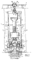
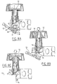
- Fig. 1 is a partly cut-away side view of a preferred embodiment of the double-action flushing device according to the invention in the rest position;
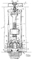
- Fig. 2 shows a view corresponding with fig. 1 of the flushing device in the intermediate flushing position;
- Fig. 3 shows a view corresponding with fig. 1 and 2 of the flushing device during a full flushing;
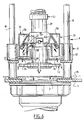
- Fig. 4 shows a view corresponding with the foregoing figures of the device when the full flushing is almost completed;
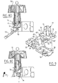
- Fig. 5 is an enlarged detail view of the auxiliary float of the double-action flushing device close to the end of the full flushing;
- Fig. 6 is a view corresponding with fig. 5 showing the auxiliary float when the valve is opened at the end of the full flushing;
- Fig. 7 is a partly sectional, perspective detail view of the auxiliary float;
- Fig. 8A to 8E show an alternative embodiment of the operating means intended for flush interruption; and
- Fig. 9 is a detail view of a component of the operating means of fig. 8.
- A double-
action flushing device 1 for a water closet is provided with avalve 2 which is moveable between a closing position (fig. 1) in which it closes adischarge opening 3 of a cistern 4, a full flushing position (fig. 3,4) in which it leaves thedischarge opening 3 completely open and an intermediate flushing position (fig. 2). The discharge opening 3 which is closed byvalve 2 is arranged in thebottom 5 of the cistern 4 and communicates via a coupling piece 7 with a flush tube (not shown) leading to a toilet bowl. Theflushing device 1 further has operating means 10, which are connected tovalve 2, in addition to a main float 8 which is connected tovalve 2 and holdsvalve 2 in its intermediate flushing position, and anauxiliary float 9 which holds thevalve 2 in its full flushing position. The main float 8 is therein fixed tovalve 2, while theauxiliary float 9 can be coupled directly tovalve 2 by means of the operating means 10. - The operating means 10 comprise a
push button 11 consisting of twoparts Push button 11 is received in ahousing 12 which is connected in turn to thecover 6 of cistern 4. The lower end ofpush button 11 engages on aplunger rod 13 which is slidably received inhousing 12 and provided on its bottom end with aprotrusion 39 which co-acts with alever 15. The latter is arranged in ayoke 14 for pivoting round ashaft 16, whichyoke 14 rests onlegs 17 which are received in abase 18 arranged on thebottom 5 of cistern 4. The lower end parts oflegs 17 are enclosed by asleeve 19 manufactured from a bearing material, the purpose of which will be elucidated hereinbelow. - The
lever 15 is connected to a pull wire orchain 20 which has a plurality ofsteps 21 arranged with interspacing. Clamped between twoadjacent steps 21 ofpull wire 20 is alip 22 which is fixed to the top edge of anoverflow tube 23. In the shown rest position theoverflow tube 23 has the purpose of preventing the level of thewater 25 in cistern 4 reaching the upper edge of cistern 4 in the unforeseen case that a valve in the water supply were not to function properly. Should this be the case, thewater 25 will rise in the cistern to the upper edge ofoverflow tube 23, whereafter the water will flow over this edge into thetube 23 and will flow therefrom into the discharge tube leading to the toilet bowl. The underside ofoverflow tube 23 is provided with a connectingpiece 28 with internal screw thread into which is screwed alower tube 29 which has on its underside adouble flange 24 in which the actualannular valve 2 is arranged. Theoverflow tube 23 is further provided with anouter screw thread 26 onto which is screwed an O-ring 27 which fixes the main float 8, which will want to move to the surface of the water as a result of the upward force exerted thereon by thewater 25. - The
auxiliary float 9 is received in aholder 31 which is fixed onto thebase 18 and is provided with twoopenings 32 through which protrude thebearing sleeves 19 of thelegs 17. In addition, theholder 31 has acentral opening 40 through which is placed thelower tube 29 bearing thevalve 2. In theholder 31, which has a plurality ofoutflow apertures 34 in its bottom, are arranged twofloat bodies 33, which together form theauxiliary float 9 and which each carry asnap connecting element 36 and which are displaceable inholder 31along guide arms 41 of aguide block 35. Theguide arms 41 run at an incline relative to the direction of displacement ofvalve 2, whereby thesnap connecting elements 36 can be placed in and out of engagement with anannular rib 37 arranged onlower tube 29 and anannular groove 38 recessed intolower tube 29. - Both
float bodies 33 are substantially semi-cylindrical in shape and open on their underside (fig. 7). Thefloat bodies 33 each have asemi-cylindrical recess 48 with which they close round the central standingedge 40 ofholder 31 and thelower tube 29 protruding therethrough. Thesnap connecting elements 36 are arranged on the side of therecesses 48 facing toward thetube 29. Theholder 31 has aninner diameter 43 which is slightly larger than the external dimensions of thefloat bodies 33, so that they are movable to and from thelower tube 29 in theinterior 43 of the holder. Thefloat bodies 33 further have guidegrooves 42 on either side which co-act with theguide arms 41 ofguide block 35. Bothguide arms 41 andguide grooves 42 are embodied at an incline relative to the longitudinal axis of theoverflow tube 23 andlower tube 29 which determine the direction of displacement ofvalve 2. Theguide block 35 is formed by abridge piece 46 which has on its outerends protruding parts 44 which are received inopenings 45 in the wall ofholder 31. Thebridge piece 46 further has acentral aperture 49 through which thelower tube 29 protrudes. Fixed ontobridge piece 46 arecaps 47 which carry theactual guide arms 41. - When the
auxiliary float 9 is under water a determined quantity of air will always be confined in thefloat bodies 33, whereby they will be subjected to an upward force. Thefloat bodies 33 will hereby move upward, in as far as this is allowed byguide block 35. Thefloat bodies 33 will herein be urged towards each other and towardslower tube 29 as a result of the sloping position ofguide arms 41 and guidegrooves 42. Thus is realized that thesnap connecting elements 36 always lie against the wall oflower tube 29 under a bias produced by the upward force. The operation of the device is now as follows. - When, starting from the rest position shown in fig. 1, a user depresses the
push button 11 to the position shown in fig. 2 for a partial flushing, theplunger rod 13 is moved downward through a part of its maximum stroke wherebylever 15 is pivoted counter-clockwise to the position shown in fig. 2 andoverflow tube 23 is moved upward, carryingvalve 2 therewith.Discharge opening 3 is hereby opened, whereby thewater 25 can flow out of cistern 4 to the toilet bowl. During the upward movement ofoverflow tube 23 thelower tube 29 connected thereto is pulled through theopenings auxiliary float 9 until the moment when thesnap connecting elements 36 on theinner walls 48 offloat bodies 33 reach theperipheral rib 37 oflower tube 29. When somuch water 25 eventually flows out of cistern 4 that the water level drops below the main float 8, the assembly offloats 8,9,tubes valve 2 will, as a result of the reduced upward force on this float 8, drop back to the rest position shown in fig. 1 in whichvalve 2 closes thedischarge opening 3. At that moment the cistern is only partly emptied, whereby the water consumption associated with this flushing is relatively small. - If more flushing water is deemed necessary to clean the toilet bowl, the
push button 11 is depressed from the position shown in fig. 1 past the position shown in fig. 2 to the position shown in fig. 3. Thepush button half 11A is herein depressed further than the half 11B, whereby theplunger rod 13 is displaced further than in the preceding case and theoverflow tube 23 withlower tube 29 and avalve 2 connected thereto are also carried further upward. Thedischarge opening 3 is now left clear again, wherebywater 25 will flow from cistern 4 to the toilet bowl. In this case, as a result of the upward directed actuating force on thelower tube 29, thefloat bodies 33 will, when theperipheral rib 37 of thelower tube 29 reaches thesnap connecting elements 36, be pushed apart counter to the bias exerted by the upward force onfloat bodies 33, wherebyrib 37 is pulled past the snap connection means 36. Herein thesnap connecting elements 36 will then fall into theperipheral groove 38 oflower tube 29. - When the water level in cistern 4 falls below the main float 8, the assembly of
floats 8,9,tubes valve 2 should begin to descend again. The downward movement of the assembly is however prevented in that thelower tube 29 is fixedly clamped with itsperipheral groove 38 between thesnap connecting elements 36 offloat bodies 33. The last water remnants in cistern 4 can thus also leave cistern 4 through the still not closeddischarge opening 3. Snap connectingelements 36 remain pressed ingroove 38 because an upward force is still exerted onfloat bodies 33 as a result of the fact that in theholder 31 there still remains a quantity ofwater 51 on which thefloat bodies 33 float. This remaining quantity of water flows slowly away through theoutflow apertures 34, whereby the upward force onfloat bodies 33 decreases and they sink downward and away from each other with theirguide groove 42 alongguide arms 41. The force with whichconnection elements 36 are pressed intogroove 38 hereby continues to decrease further (fig. 6) wherebytubes auxiliary float 9 under the influence of their weight and thevalve 2 will again assume its rest position. As already stated, the cistern 4 is completely emptied herein, so that a full flushing has taken place. Theholder 31 withoutflow apertures 34 therefore functions herein as slowing mechanism, whereby falling shut ofvalve 2 is delayed until cistern 4 is emptied entirely. - In this manner a flushing device is thus obtained with which the cistern 4 can be wholly or partly emptied as the user desires, depending on the waste in the toilet bowl. In the case of a partial flushing the flushing water volume can be adjusted by moving the main float 8 along the
screw thread 26 ofoverflow tube 23. Through a suitable choice of the volume offloat bodies 33,holder 31 and the dimensions of outflow apertures 34 a delay in closing can be obtained such that in a full flushing the entire cistern 4 is really emptied. - The above described flushing device can otherwise also be used in combination with a flush interruption device, for instance of the type as described in applicant's earlier Netherlands patent application 9100986. Therein, when the control button is depressed for the first time the assembly of
overflow tube 23 andlower tube 29 is moved so far upward by a transmission element which is under strain of both tension and pressure that therib 37 oflower tube 29 is pulled past theconnection elements 36. These then engage in thegroove 38 and thus holdvalve 2 open, whereby in principle a full flushing is performed. By now depressing the button for a second time the overflow tube and lower tube are pressed downward by the transmission element, wherein thefloat bodies 33 of the auxiliary float are pushed apart and thevalve 2 returned to the closing position. - An alternative embodiment of a flush interruption device is shown in figure 8. The
push button 52 is formed integrally in this case. Flush interruption takes place by depressing thebutton 52 twice. In the first rest position oflever 53 as shown in fig. 8A, the valve (not shown) is closed. Depressing of thebutton 52 results in atongue 54 of a bell-shapedmember 57 which is pivotally suspended on apressure pin 56 by means of ashaft 55 engaging in arecess 58 inlever 53. Due to the engagement thelever 53 tilts to the second rest position (Fig. 8C), wherein the valve is opened. Due to the pivotal suspension of bell-shapedmember 57 onpressure pin 56 it will be possible for a tilting movement of the bell-shaped member to occur during the up and downward movement of the pressure pin (Fig. 8B). During the first downward movement ofpressure pin 56 the engagement betweentongue 54 andrecess 58 oflever 53 is broken. Theflange 60 of bell-shapedmember 57 now engages onlever 53 at a second point ofengagement 61. Thetip 62 of thefin 63 onlever 53 falls into a slot (not shown) in thepressure pin 56. During the second upward movement ofpressure pin 56 the above mentioned suspension of bell-shapedmember 57 onpressure pin 56 prevents the bell-shaped member from being caught behind thefin 63 of the lever. - When the
button 52 is released it will return to its starting position under the influence of the spring action of spring 59 (Fig. 8D). Thelever 53 remains in its lifted position during the flushing. Whenbutton 52 is now depressed a second time thetip 62 will remain caught behind theflange 60 of bell-shapedmember 57. The bell-shapedmember 57 tilts. The guiding of thepressure pin 56 in a screw threaded bush (not shown) prevents the pressure pin being pushed aside by the tilting of the bell-shaped member. - In the position according to Fig. 8E the
tip 62 offin 63 serves as point of rotation while a force is exerted on thelever 53 as according to arrow 64. Thetongue 54 therein also presses against thefin 63 oflever 53 which thereby tilts to the position in which the valve is closed (Fig. 8A). Partly because of the flow of water in the bottom of the water closet the closing of the valve will take place very rapidly. - Fig. 9 shows in perspective a number of structural details which enable optimum functioning of the mechanism outlined above. It shows the bell-shaped
member 57 which is provided on its underside with atongue 54 interrupted by arecess 65. The tongue parts engage in cup-shapedrecesses 58 in thelever 53. The cup-shapedrecesses 58 are mutually separated by a rib 66 which prevents the bell-shapedmember 57 becoming jammed with its twoflanges 60' and 60" between respectively the edge 67 of the pressure pin housing 68 (Fig. 8E) and therecess 58 during the tilting to its first rest position. The fin further has local thickenedportions 69 which bound the tilting of the bell-shaped member. Both chamferedsides 70 of the bell-shapedmember 57 co-act with butting faces in the pressure pin housing 68 (not shown). The bell-shaped member further has two flat stop sides 71. Both steps ensure that in the rest position the bell-shapedmember 57 is always positioned at right angles to and straight under thepressure pin 56. - Finally, it will be apparent to the skilled person that more or fewer than two float bodies could also be used in the
auxiliary float 9. Other connecting mechanisms betweenauxiliary float 9 andtube 29 are also conceivable. Of particular importance is that by directly connecting thefloats 8,9 to the valve 2 a simple, reliable and relatively inexpensive construction is obtained.
Claims (9)
- Double-action flushing device (1) for a water closet, provided with a valve (2) which is moveable between a closing position in which it closes a discharge opening (3) of a cistern (4), a full flushing position in which it leaves the discharge opening (3) completely open and at least one intermediate position, operating means (10) connected to the valve, a main float (8) co-acting with the valve (2) for holding thereof in the intermediate flushing position and at least one auxiliary float (9) co-acting with and holding the valve (2) in the full flushing position, characterized in that at least one of the floats (8,9) is directly connectable to the valve (2).
- Double-action flushing device (1) as claimed in claim 1, characterized in that the main float (8) is fixed to the valve (2) and the auxiliary float (9) is directly connectable to the valve (2) by the operating means (10).
- Double-action flushing device (1) as claimed in claim 2, characterized in that the auxiliary float (9) is automatically releasable from the valve (2) at the end of the full flushing.
- Double-action flushing device (1) as claimed in claim 2 or 3, characterized in that the valve (2) and the auxiliary float (9) have co-acting snap connecting means (36,38).
- Double-action flushing device (1) as claimed in claim 4, characterized in that the auxiliary float (9) comprises at least one float body (33) which carries a snap connecting element (36) and which is moveable along a guiding (41) which is inclining relative to the direction of displacement of the valve (2).
- Double-action flushing device (1) as claimed in claim 4 or 5, characterized by means for delaying the release of the auxiliary float (9) from the valve (2).
- Double-action flushing device (1) as claimed in claim 6, characterized in that the release-delaying means comprise a holder (31) which at least partly encloses the float body (33), determines the sloping guiding (41) thereof and has at least one outflow aperture (34).
- Double-action flushing device for a water closet, provided with a valve (2) which is moveable between a closing position in which it closes a discharge opening (3) of a cistern (4) and a flushing position in which it leaves the discharge opening (3) completely open, further provided with operating means for the valve, which operating means consist of a lever (53) which is moveable between two end positions, wherein the transition from the first end position to the second end position in order to start a flushing is effected by the engagement of a tongue (54) of a bell-shaped member (57) with a point of engagement (58) on the lever (53) and the transition from the second end position to the first end position in order to interrupt the flushing is actively effected by engagement of a flange (60) of the bell-shaped member (57) with a fin (62) on the lever (53).
- Water closet provided with a double-action flushing device (1) as claimed in any of the foregoing claims.
Applications Claiming Priority (4)
| Application Number | Priority Date | Filing Date | Title |
|---|---|---|---|
| NL9500316 | 1995-02-17 | ||
| NL9500316A NL9500316A (en) | 1995-02-17 | 1995-02-17 | Double-acting flushing arrangement |
| NL1001567A NL1001567C1 (en) | 1995-02-17 | 1995-11-03 | Double-acting flushing device. |
| NL1001567 | 1995-11-03 |
Publications (2)
| Publication Number | Publication Date |
|---|---|
| EP0727533A2 true EP0727533A2 (en) | 1996-08-21 |
| EP0727533A3 EP0727533A3 (en) | 1996-10-30 |
Family
ID=26642220
Family Applications (1)
| Application Number | Title | Priority Date | Filing Date |
|---|---|---|---|
| EP96200356A Ceased EP0727533A3 (en) | 1995-02-17 | 1996-02-14 | Double acting flush system |
Country Status (2)
| Country | Link |
|---|---|
| EP (1) | EP0727533A3 (en) |
| NL (1) | NL1001567C1 (en) |
Cited By (15)
| Publication number | Priority date | Publication date | Assignee | Title |
|---|---|---|---|---|
| WO1998022666A1 (en) * | 1996-11-21 | 1998-05-28 | Alert Ii | Water saving cistern for toilets |
| EP0845560A1 (en) * | 1996-11-29 | 1998-06-03 | Wisa B.V. | Operating device for a flushing installation |
| ES2136547A1 (en) * | 1997-07-09 | 1999-11-16 | Fominaya Agullo Pablo | Device for total or partial discharge of a lavatory cistern |
| EP0997585A1 (en) | 1998-10-27 | 2000-05-03 | Wisa B.V. | Flush mechanism for a water closet and operating means therefor |
| ES2151374A1 (en) * | 1998-01-29 | 2000-12-16 | Idrols Sa | Mechanism for the total or selective flushing of lavatory cisterns. |
| EP1065323A1 (en) * | 1999-07-02 | 2001-01-03 | Pablo Fominaya Agullo | Device for the total or partial flushing of a toilet tank |
| WO2002012645A1 (en) * | 2000-08-09 | 2002-02-14 | Idrols, S.A. | Mechanism for full or selective flushing of toilet tanks |
| EP1088942A3 (en) * | 1999-09-28 | 2003-01-02 | Franz Viegener II GmbH & Co. KG. | Actuating device |
| WO2004027170A1 (en) * | 2002-09-19 | 2004-04-01 | Caroma Industries Limited | A dual actuation button assembly |
| WO2004094736A1 (en) * | 2003-04-22 | 2004-11-04 | Idrols, S.A. | Mechanism for full or selective flushing of toilet tanks |
| ES2224793A1 (en) * | 2002-07-02 | 2005-03-01 | Idrols, S.A. | Pneumatic unloader for use in toilet, has auxiliary float connected to eccentric axis of overflow pipe, crossbar inserted into overflow pipe and bell shaped object provided with tilting part and crossbar |
| EP1580338A2 (en) | 2004-03-23 | 2005-09-28 | VIEGA GmbH & Co. KG. | Flush valve for a flushing cistern |
| AU2003254408B2 (en) * | 2002-09-19 | 2008-02-28 | Caroma Industries Limited | A dual actuation button assembly |
| WO2011018712A3 (en) * | 2009-08-13 | 2011-05-19 | Ecobeta A/S | Dual flush toilet valve system |
| US20140165280A1 (en) * | 2012-12-18 | 2014-06-19 | Geberit International Ag | Actuating device for a drain fitting |
Citations (7)
| Publication number | Priority date | Publication date | Assignee | Title |
|---|---|---|---|---|
| EP0010945A1 (en) * | 1978-11-05 | 1980-05-14 | Zeev Dr. Raz | Toilet bowl flush system |
| FR2548328A1 (en) * | 1983-07-01 | 1985-01-04 | Geberit Ag | Tank discharge valve |
| DE8502988U1 (en) * | 1985-02-04 | 1985-07-18 | Altmann, Konrad, Dipl.-Phys. Dr., 8000 München | WC - cistern |
| FR2660679A1 (en) * | 1990-04-06 | 1991-10-11 | Spmp Sa | Control device with push-button and tilting cam for flushing mechanism |
| DE9110092U1 (en) * | 1990-08-29 | 1991-10-17 | Geberit Ag, Jona, St.Gallen | Actuating device on the drain valve of a cistern |
| NL9100986A (en) * | 1991-06-07 | 1993-01-04 | Wisa Bv | Flushing device with interrupt mechanism |
| EP0578892A1 (en) * | 1991-02-01 | 1994-01-19 | Etablissements Porcher | Flushing device allowing the delivery of different, predetermined quantities of water |
-
1995
- 1995-11-03 NL NL1001567A patent/NL1001567C1/en not_active IP Right Cessation
-
1996
- 1996-02-14 EP EP96200356A patent/EP0727533A3/en not_active Ceased
Patent Citations (7)
| Publication number | Priority date | Publication date | Assignee | Title |
|---|---|---|---|---|
| EP0010945A1 (en) * | 1978-11-05 | 1980-05-14 | Zeev Dr. Raz | Toilet bowl flush system |
| FR2548328A1 (en) * | 1983-07-01 | 1985-01-04 | Geberit Ag | Tank discharge valve |
| DE8502988U1 (en) * | 1985-02-04 | 1985-07-18 | Altmann, Konrad, Dipl.-Phys. Dr., 8000 München | WC - cistern |
| FR2660679A1 (en) * | 1990-04-06 | 1991-10-11 | Spmp Sa | Control device with push-button and tilting cam for flushing mechanism |
| DE9110092U1 (en) * | 1990-08-29 | 1991-10-17 | Geberit Ag, Jona, St.Gallen | Actuating device on the drain valve of a cistern |
| EP0578892A1 (en) * | 1991-02-01 | 1994-01-19 | Etablissements Porcher | Flushing device allowing the delivery of different, predetermined quantities of water |
| NL9100986A (en) * | 1991-06-07 | 1993-01-04 | Wisa Bv | Flushing device with interrupt mechanism |
Cited By (21)
| Publication number | Priority date | Publication date | Assignee | Title |
|---|---|---|---|---|
| WO1998022666A1 (en) * | 1996-11-21 | 1998-05-28 | Alert Ii | Water saving cistern for toilets |
| EP0845560A1 (en) * | 1996-11-29 | 1998-06-03 | Wisa B.V. | Operating device for a flushing installation |
| NL1004653C2 (en) * | 1996-11-29 | 1998-06-03 | Wisa Bv | Control device for a flushing installation. |
| ES2136547A1 (en) * | 1997-07-09 | 1999-11-16 | Fominaya Agullo Pablo | Device for total or partial discharge of a lavatory cistern |
| ES2151374A1 (en) * | 1998-01-29 | 2000-12-16 | Idrols Sa | Mechanism for the total or selective flushing of lavatory cisterns. |
| ES2187247A1 (en) * | 1998-01-29 | 2003-05-16 | Idrols Sa | Mechanism for the total or selective flushing of lavatory cisterns. |
| EP0997585A1 (en) | 1998-10-27 | 2000-05-03 | Wisa B.V. | Flush mechanism for a water closet and operating means therefor |
| EP1065323A1 (en) * | 1999-07-02 | 2001-01-03 | Pablo Fominaya Agullo | Device for the total or partial flushing of a toilet tank |
| EP1088942A3 (en) * | 1999-09-28 | 2003-01-02 | Franz Viegener II GmbH & Co. KG. | Actuating device |
| WO2002012645A1 (en) * | 2000-08-09 | 2002-02-14 | Idrols, S.A. | Mechanism for full or selective flushing of toilet tanks |
| ES2224793A1 (en) * | 2002-07-02 | 2005-03-01 | Idrols, S.A. | Pneumatic unloader for use in toilet, has auxiliary float connected to eccentric axis of overflow pipe, crossbar inserted into overflow pipe and bell shaped object provided with tilting part and crossbar |
| WO2004027170A1 (en) * | 2002-09-19 | 2004-04-01 | Caroma Industries Limited | A dual actuation button assembly |
| US7263728B2 (en) | 2002-09-19 | 2007-09-04 | Caroma Industries Limited | Dual actuation button assembly |
| CN100360748C (en) * | 2002-09-19 | 2008-01-09 | 卡罗马工业有限公司 | A dual actuation button assembly |
| AU2003254408B2 (en) * | 2002-09-19 | 2008-02-28 | Caroma Industries Limited | A dual actuation button assembly |
| WO2004094736A1 (en) * | 2003-04-22 | 2004-11-04 | Idrols, S.A. | Mechanism for full or selective flushing of toilet tanks |
| EP1580338A2 (en) | 2004-03-23 | 2005-09-28 | VIEGA GmbH & Co. KG. | Flush valve for a flushing cistern |
| EP1580338A3 (en) * | 2004-03-23 | 2006-08-02 | VIEGA GmbH & Co. KG. | Flush valve for a flushing cistern |
| WO2011018712A3 (en) * | 2009-08-13 | 2011-05-19 | Ecobeta A/S | Dual flush toilet valve system |
| US20140165280A1 (en) * | 2012-12-18 | 2014-06-19 | Geberit International Ag | Actuating device for a drain fitting |
| EP2746472A1 (en) * | 2012-12-18 | 2014-06-25 | Geberit International AG | Actuation device for a discharge fitting |
Also Published As
| Publication number | Publication date |
|---|---|
| EP0727533A3 (en) | 1996-10-30 |
| NL1001567C1 (en) | 1996-08-22 |
Similar Documents
| Publication | Publication Date | Title |
|---|---|---|
| EP0727533A2 (en) | Double acting flush system | |
| EP0268381B1 (en) | Dual flush cistern mechanism | |
| US5548850A (en) | Toilet with two flush modalities | |
| US4225987A (en) | Variable volume control for toilet flush tanks | |
| US5657494A (en) | Toilet flushing device | |
| US5754986A (en) | Water-saving device of water tank for flush toilet | |
| US6094753A (en) | Flush valve with partial-flush function | |
| US20110197974A1 (en) | Draining Apparatus | |
| US6584622B1 (en) | Method and device for timer-controlled flushing of water toilets | |
| KR101970460B1 (en) | Water saving closet | |
| US5713086A (en) | Flushing device for a toilet | |
| US4240168A (en) | Combination commode construction | |
| CN113597493A (en) | Washing water tank device and water-washing toilet device provided with same | |
| US4945578A (en) | Toilet flush control device | |
| US5829067A (en) | Toilet seat lift assembly | |
| US5720053A (en) | Apparatus for regulating the quantity of liquid for the flushing of toilet bowls | |
| US5191662A (en) | Flush limiting mechanism | |
| US4082110A (en) | Water level control for toilet having vertical float | |
| US20110203042A1 (en) | Water saving flapper valve weight apparatus | |
| EP0801179A2 (en) | Device for controlling the discharge valve of a lavatory flush tank | |
| WO1996029481A1 (en) | Float-controlled dual flush valve | |
| US5483706A (en) | Flush device for toilet | |
| GB2396163A (en) | Toilet cistern valve assembly | |
| GB2304742A (en) | Dual-flush facility for a siphon-discharge flushing cistern | |
| US4086667A (en) | Flush control device for conserving water |
Legal Events
| Date | Code | Title | Description |
|---|---|---|---|
| PUAI | Public reference made under article 153(3) epc to a published international application that has entered the european phase |
Free format text: ORIGINAL CODE: 0009012 |
|
| AK | Designated contracting states |
Kind code of ref document: A2 Designated state(s): AT BE CH DE DK ES FR GB GR IE IT LI LU MC NL PT SE |
|
| AX | Request for extension of the european patent |
Free format text: LT PAYMENT 960214;SI PAYMENT 960214 |
|
| RAX | Requested extension states of the european patent have changed |
Free format text: LT PAYMENT 960214;SI PAYMENT 960214 |
|
| PUAL | Search report despatched |
Free format text: ORIGINAL CODE: 0009013 |
|
| AK | Designated contracting states |
Kind code of ref document: A3 Designated state(s): AT BE CH DE DK ES FR GB GR IE IT LI LU MC NL PT SE |
|
| AX | Request for extension of the european patent |
Free format text: LT PAYMENT 960214;SI PAYMENT 960214 |
|
| 17P | Request for examination filed |
Effective date: 19970429 |
|
| 17Q | First examination report despatched |
Effective date: 19991008 |
|
| GRAG | Despatch of communication of intention to grant |
Free format text: ORIGINAL CODE: EPIDOS AGRA |
|
| STAA | Information on the status of an ep patent application or granted ep patent |
Free format text: STATUS: THE APPLICATION HAS BEEN REFUSED |
|
| 18R | Application refused |
Effective date: 20020803 |