EP0726610B1 - A method of sealing and packaging a lead acid bipolar battery by using polyolefin based materials, and relevant product - Google Patents
A method of sealing and packaging a lead acid bipolar battery by using polyolefin based materials, and relevant product Download PDFInfo
- Publication number
- EP0726610B1 EP0726610B1 EP95119600A EP95119600A EP0726610B1 EP 0726610 B1 EP0726610 B1 EP 0726610B1 EP 95119600 A EP95119600 A EP 95119600A EP 95119600 A EP95119600 A EP 95119600A EP 0726610 B1 EP0726610 B1 EP 0726610B1
- Authority
- EP
- European Patent Office
- Prior art keywords
- frames
- stack
- electrode
- electrodes
- battery
- Prior art date
- Legal status (The legal status is an assumption and is not a legal conclusion. Google has not performed a legal analysis and makes no representation as to the accuracy of the status listed.)
- Expired - Lifetime
Links
Images


Classifications
-
- H—ELECTRICITY
- H01—ELECTRIC ELEMENTS
- H01M—PROCESSES OR MEANS, e.g. BATTERIES, FOR THE DIRECT CONVERSION OF CHEMICAL ENERGY INTO ELECTRICAL ENERGY
- H01M10/00—Secondary cells; Manufacture thereof
- H01M10/06—Lead-acid accumulators
- H01M10/18—Lead-acid accumulators with bipolar electrodes
-
- H—ELECTRICITY
- H01—ELECTRIC ELEMENTS
- H01M—PROCESSES OR MEANS, e.g. BATTERIES, FOR THE DIRECT CONVERSION OF CHEMICAL ENERGY INTO ELECTRICAL ENERGY
- H01M8/00—Fuel cells; Manufacture thereof
- H01M8/02—Details
- H01M8/0271—Sealing or supporting means around electrodes, matrices or membranes
- H01M8/0273—Sealing or supporting means around electrodes, matrices or membranes with sealing or supporting means in the form of a frame
-
- Y—GENERAL TAGGING OF NEW TECHNOLOGICAL DEVELOPMENTS; GENERAL TAGGING OF CROSS-SECTIONAL TECHNOLOGIES SPANNING OVER SEVERAL SECTIONS OF THE IPC; TECHNICAL SUBJECTS COVERED BY FORMER USPC CROSS-REFERENCE ART COLLECTIONS [XRACs] AND DIGESTS
- Y02—TECHNOLOGIES OR APPLICATIONS FOR MITIGATION OR ADAPTATION AGAINST CLIMATE CHANGE
- Y02E—REDUCTION OF GREENHOUSE GAS [GHG] EMISSIONS, RELATED TO ENERGY GENERATION, TRANSMISSION OR DISTRIBUTION
- Y02E60/00—Enabling technologies; Technologies with a potential or indirect contribution to GHG emissions mitigation
- Y02E60/10—Energy storage using batteries
-
- Y—GENERAL TAGGING OF NEW TECHNOLOGICAL DEVELOPMENTS; GENERAL TAGGING OF CROSS-SECTIONAL TECHNOLOGIES SPANNING OVER SEVERAL SECTIONS OF THE IPC; TECHNICAL SUBJECTS COVERED BY FORMER USPC CROSS-REFERENCE ART COLLECTIONS [XRACs] AND DIGESTS
- Y02—TECHNOLOGIES OR APPLICATIONS FOR MITIGATION OR ADAPTATION AGAINST CLIMATE CHANGE
- Y02E—REDUCTION OF GREENHOUSE GAS [GHG] EMISSIONS, RELATED TO ENERGY GENERATION, TRANSMISSION OR DISTRIBUTION
- Y02E60/00—Enabling technologies; Technologies with a potential or indirect contribution to GHG emissions mitigation
- Y02E60/30—Hydrogen technology
- Y02E60/50—Fuel cells
-
- Y—GENERAL TAGGING OF NEW TECHNOLOGICAL DEVELOPMENTS; GENERAL TAGGING OF CROSS-SECTIONAL TECHNOLOGIES SPANNING OVER SEVERAL SECTIONS OF THE IPC; TECHNICAL SUBJECTS COVERED BY FORMER USPC CROSS-REFERENCE ART COLLECTIONS [XRACs] AND DIGESTS
- Y10—TECHNICAL SUBJECTS COVERED BY FORMER USPC
- Y10T—TECHNICAL SUBJECTS COVERED BY FORMER US CLASSIFICATION
- Y10T29/00—Metal working
- Y10T29/49—Method of mechanical manufacture
- Y10T29/49002—Electrical device making
- Y10T29/49108—Electric battery cell making
- Y10T29/4911—Electric battery cell making including sealing
Definitions
- the present invention refers to the construction of hermetically sealed lead acid bipolar batteries. More specifically, the invention relates to a method of forming and assembling the seal components of the electrode stack and sealing same by molding a final packaging frame thereon.
- the electrode stack is formed by stacking the single frames on one another in a sequence so as to alternate electrodes having opposite polarities and interposing glass microfiber separators therebetween.
- the above cited frames act as spacer members between the cells, as their coupling forms a cell unit comprising the negative electrode, the separator and the positive electrode, as known in the art.
- frames are provided with one or a number of channels communicating with the inside of the cell.
- each frame has a pair of grooves running along its longer side, whereby coupling of two consecutive frames determines an inner double channel for filling the cell and letting the gas out, respectively.
- the main condition for ensuring correct operation of the bipolar battery is the effectiveness of the sealing between the coupled frames. Sealing action of each cell must be hermetical with respect to adjacent cells and the outside.
- bipolar batteries has been hindered by inadequate solutions being adopted for providing hermetical sealing to the cells.
- the present invention solves the sealing and packaging problems of lead acid bipolar batteries by:
- the present invention represents an improvement with respect to prior art sealing and packaging of bipolar batteries.
- the present invention provides a lead acid bipolar battery where coupling of its components is simple.
- the assembly of the electrode stack is rendered easy and gives a reliable and functional final product.
- the materials forming the electrode frames, the spacer frames and the end plates are chemically compatible therebetween and with the molding material so as to heat seal in the contact zones during packaging.
- the method of constructing a battery according to the present invention comprises firstly the step of providing a series of electrodes 10, of which the intermediate ones are bipolar while the terminal electrodes are monopolar.
- Each electrode 10 consists of a substantially rectangular plate of electrically conductive material.
- a peripheral frame of polyolefinic material for stiffening the plate, sealing its the edge and providing a reference member useful in applying the active compound to the faces of the plate.
- the frame is obtained by pressure molding and welding of two complementary plastic half-frames separately obtained by injection molding in a separate mold.
- the half-frames are of a polyolefin based material being modified with polar groups adapted to bind chemically to the conductive substrate.
- each spacer is frame-like members having a shape corresponding to that of the electrodes and alternately arranged therewith. Besides keeping the predetermined distance between adjacent electrodes, each spacer acts as an outer housing for a conventional porous layer 12 supporting the electrolyte. Typically, glass microfiber layers are use for this purpose.
- the spacer is obtained through injection molding of polyolefin based material chemically compatible with the plastic material constituting the frames so as to solder thereto during molding.
- polyolefin based material chemically compatible with the plastic material constituting the frames so as to solder thereto during molding.
- talc added polypropylene or glass added polypropylene are suitable for forming the spacers.
- the added materials have to be chosen so as to provide greater stiffness and size accuracy with respect to the electrode frames, provide the desired dimension of the assembled battery stack and attain greater heat resistance during molding of the outer housing, as will be apparent herein after.
- each spacer 13 is so shaped as to contain the electrodes 10. Therefore, transverse seats 14 are obtained along the edge of both of their sides. Seats 14 prevent the spacer and the electrode frame from sliding relative to one another during manufacturing and also improve the sealing.
- a vertical, preferably tapered bore 15 is formed in each spacer for filling the assembled battery with electrolyte (FIG.2).
- each bore 15 is formed by two pins (not shown) mounted to moving parts of the mold used for forming the spacer.
- each battery is fitted with a pair of flat end plates 16.
- the thickness of end plates 16 depends on the inner pressure acting in the pre-loading initial stage and the following stages of forming and loading. Also, the thickness depends on maximum yielding that is admissible in the center of each plate.
- end plates 16 are of a thermoplastic polymer material chemically compatible with the material forming the spacers, so as to heat seal to the molding material during packaging.
- each end plate 16 on the side facing the inside of the battery is a seat 17 for a terminal 18 welded to the end monopolar collector electrode plate.
- a thinner edge portion 21 On the outwardly facing side there is formed a thinner edge portion 21 to be filled with molding material during the final manufacturing step.
- a channel 19 Within thinner edge portion 21 a channel 19 is formed constituting a seat for hooking clips 20 adapted to keep the assembled stack firm (FIG. 10).
- a special press (not shown) which provides stacking and centering of the components, and successive pre-compression of same until the desired thickness is reached.
- Said press comprises two faces, of which one is movable and one is stationary with reference templates. Suitable pneumatic rams drive the movement of the movable face and control the drawing system.
- sealing and final packaging of the battery stack are accomplished by injection molding of a special plastic material 22, for example suitably strengthened polypropylene.
- the assembled stack is positioned within the injection mold with special means, for example plugs also serving to close the acid inlet bores, seats in the end plates, bores in the terminal current collectors, templates retractable after the closing of the mold, etc.
- special means for example plugs also serving to close the acid inlet bores, seats in the end plates, bores in the terminal current collectors, templates retractable after the closing of the mold, etc.
Landscapes
- Engineering & Computer Science (AREA)
- Manufacturing & Machinery (AREA)
- Chemical & Material Sciences (AREA)
- Chemical Kinetics & Catalysis (AREA)
- Electrochemistry (AREA)
- General Chemical & Material Sciences (AREA)
- Secondary Cells (AREA)
- Sealing Battery Cases Or Jackets (AREA)
- Polyesters Or Polycarbonates (AREA)
Abstract
Description
- The present invention refers to the construction of hermetically sealed lead acid bipolar batteries. More specifically, the invention relates to a method of forming and assembling the seal components of the electrode stack and sealing same by molding a final packaging frame thereon.
- Several prior art documents such as document EP-A-0 631 338 disclose a typical bipolar battery arrangement. The electrode stack is formed by the union of a number of frames of thermoplastic material, each of which is fitted with an inside bipolar electrode plate and has surfaces extending beyond the plate. Said extending surfaces provide coupling to adjacent frames.
- The electrode stack is formed by stacking the single frames on one another in a sequence so as to alternate electrodes having opposite polarities and interposing glass microfiber separators therebetween.
- Accordingly, the above cited frames act as spacer members between the cells, as their coupling forms a cell unit comprising the negative electrode, the separator and the positive electrode, as known in the art.
- In some prior art cases, frames are provided with one or a number of channels communicating with the inside of the cell. For example, in US Pat. No. 4,900,643 each frame has a pair of grooves running along its longer side, whereby coupling of two consecutive frames determines an inner double channel for filling the cell and letting the gas out, respectively.
- The main condition for ensuring correct operation of the bipolar battery is the effectiveness of the sealing between the coupled frames. Sealing action of each cell must be hermetical with respect to adjacent cells and the outside.
- In the past, prior art sealing was provided joining coupling frames by heat welding. In US Pat. No. 5,035,045 this is accomplished by using an infrared heater positioned in the space between the coupling surfaces of two frames. When the surfaces begin to melt, the heating unit is withdrawn and the frames are moved and into contact with each other and slightly pressed together to weld.
- An alternative approach is disclosed in US. Pat. No. 4,164,068, which makes provision of ultrasonic soldering.
- The development of bipolar batteries has been hindered by inadequate solutions being adopted for providing hermetical sealing to the cells. Among the problems which are encountered more frequently there is that of deformation of contacting surfaces due to high temperatures and relatively thin frames. This results in inadequate welding in some points of the perimeter of the frame. This also adversely affects operation of the communicating channels.
- On the other hand, welding operations are excessively complicated and costly, and are not adequate from an industrial point of view.
- The present invention solves the sealing and packaging problems of lead acid bipolar batteries by:
- a) using a different arrangement of the sealing members: the cell unit consists of the coupling of a central spacer member and opposite frames of electrodes of different polarity;
- b) using new modes of sealing cell sealing members by molding a side frame which serves to form a housing for the electrode stack and forms seats for gas outlet valves.
-
- The present invention represents an improvement with respect to prior art sealing and packaging of bipolar batteries.
- It is an object of the present invention to provide an original arrangement of the hermetic sealing members, wherein the electrode frames are coupled to a central spacer frame. Said members are stacked in series and sealed by molding a final packaging frame.
- It is another object of the present invention to provide an original solution concerning modes of sealing and packaging the electrode stack of a lead acid bipolar battery. Functionality of the system is made effective by:
- hermetic sealing of each cell with respect to the adjacent cells and the outside;
- uniform spacing between electrodes having the same polarity;
- regular dimensions of the active electrode surface;
- regular shape of cell inlet channels in order to:
- a) introduce the electrolyte easily and practically in a cell, independently of the other cells, with a speed satisfying manufacture requests;
- b) allow, at a predetermined inner pressure, the outlet of gases which form within the battery;
- contain the preloading required to gain good physical contact between the electrodes and the glass microfiber separators.
- The present invention provides a lead acid bipolar battery where coupling of its components is simple. The assembly of the electrode stack is rendered easy and gives a reliable and functional final product.
- It is another object of the present invention to provide a method of sealing the cells of a lead acid bipolar battery, simultaneously packaging the battery so as to guarantee hermetical sealing and mechanical strength to the battery in use.
- In accordance with the invention, there is provided a method as claimed in claim 1.
- In order that the present invention may be well understood there will now be described a preferred embodiment thereof, given by way of example, reference being made to the accompanying drawings, in which:
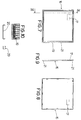
- FIG. 1
- is a schematic front view of a battery constructed according to the present invention;
- FIG. 2
- is a schematic sectional view, to an enlarged scale, taken along the line II-II of FIG. 1;
- FIG. 3
- is a top view of the battery of FIG. 1;
- FIGS. 4 and 5
- are front and side views, respectively, of a spacer member being part of the battery;
- FIGS. 6 and 7
- are plan views of the end plates of the battery;
- FIG. 9
- is a sectional view taken along line IX-IX of FIG. 7; and
- FIG. 10
- shows front and side views of a further detail mounted and detached.
-
- A plastic frame is molded on the electrode made of lead or other electrically conductive material or polymeric material (such as polyaniline, polyparaphenylene, polypirrole), or ceramic material (for example titanium carbide or molybdenum silicide). The frame is for stiffening the electrode, provide a reference during assembly, seal the edge of the electrode and eventually provide a reference for applying the desired thickness of active compound.
- Spacer frames are provided to be interposed between the electrodes and contain electrolyte supporting material, for example glass microfiber layers. The spacer frames are provided with electrolyte inlet bores and gas outlet bores.
- Stack end plates are provided.
- Bipolar electrodes are stacked between the end plates. The bipolar electrodes have active compounds applied thereto and are alternately arranged with the electrolyte support containing frames. The end electrodes are monopolar and the intermediate ones bipolar. A preloading is applied to the stack.
- The stack is preloaded in a mold and a layer of polyolefin material is molded over the stack to seal same and provide a housing for the battery. Gas outlet valves are obtained at the electrolyte inlet bores.
- To attain perfect sealing of the battery, the materials forming the electrode frames, the spacer frames and the end plates are chemically compatible therebetween and with the molding material so as to heat seal in the contact zones during packaging.
- With reference to the enclosed drawings, the method of constructing a battery according to the present invention comprises firstly the step of providing a series of
electrodes 10, of which the intermediate ones are bipolar while the terminal electrodes are monopolar. Eachelectrode 10 consists of a substantially rectangular plate of electrically conductive material. Securely and continuously fixed to the outer edge of the plate is a peripheral frame of polyolefinic material for stiffening the plate, sealing its the edge and providing a reference member useful in applying the active compound to the faces of the plate. Preferably, the frame is obtained by pressure molding and welding of two complementary plastic half-frames separately obtained by injection molding in a separate mold. Advantageously, the half-frames are of a polyolefin based material being modified with polar groups adapted to bind chemically to the conductive substrate. - With reference to FIGS. 4 to 6, there is shown a
spacer 13 according to the present invention. The spacers are frame-like members having a shape corresponding to that of the electrodes and alternately arranged therewith. Besides keeping the predetermined distance between adjacent electrodes, each spacer acts as an outer housing for a conventionalporous layer 12 supporting the electrolyte. Typically, glass microfiber layers are use for this purpose. - Preferably, the spacer is obtained through injection molding of polyolefin based material chemically compatible with the plastic material constituting the frames so as to solder thereto during molding. For example, talc added polypropylene or glass added polypropylene are suitable for forming the spacers. The added materials have to be chosen so as to provide greater stiffness and size accuracy with respect to the electrode frames, provide the desired dimension of the assembled battery stack and attain greater heat resistance during molding of the outer housing, as will be apparent herein after.
- The cross-section of spacers 13 (FIG. 6) is so shaped as to contain the
electrodes 10. Therefore,transverse seats 14 are obtained along the edge of both of their sides.Seats 14 prevent the spacer and the electrode frame from sliding relative to one another during manufacturing and also improve the sealing. A vertical, preferably tapered bore 15 is formed in each spacer for filling the assembled battery with electrolyte (FIG.2). Advantageously, each bore 15 is formed by two pins (not shown) mounted to moving parts of the mold used for forming the spacer. - Referring to FIGS. 7 to 9, each battery is fitted with a pair of
flat end plates 16. The thickness ofend plates 16 depends on the inner pressure acting in the pre-loading initial stage and the following stages of forming and loading. Also, the thickness depends on maximum yielding that is admissible in the center of each plate. Advantageously,end plates 16 are of a thermoplastic polymer material chemically compatible with the material forming the spacers, so as to heat seal to the molding material during packaging. - Obtained in each
end plate 16 on the side facing the inside of the battery is aseat 17 for a terminal 18 welded to the end monopolar collector electrode plate. On the outwardly facing side there is formed athinner edge portion 21 to be filled with molding material during the final manufacturing step. Within thinner edge portion 21 achannel 19 is formed constituting a seat for hookingclips 20 adapted to keep the assembled stack firm (FIG. 10). - In assembling the components of the battery (end plates, monopolar and bipolar electrode plates with active compound, spacers, etc.) a special press (not shown) is used which provides stacking and centering of the components, and successive pre-compression of same until the desired thickness is reached.
- Said press comprises two faces, of which one is movable and one is stationary with reference templates. Suitable pneumatic rams drive the movement of the movable face and control the drawing system.
- The assembled and pre-compressed stacks are kept in position by hooking
clips 20 fitted to the sides of the stacks in the special seats ofend plates 16. - Referring to FIG. 2, sealing and final packaging of the battery stack are accomplished by injection molding of a special
plastic material 22, for example suitably strengthened polypropylene. - Then, the assembled stack is positioned within the injection mold with special means, for example plugs also serving to close the acid inlet bores, seats in the end plates, bores in the terminal current collectors, templates retractable after the closing of the mold, etc.
Claims (2)
- A method of sealing and packaging lead acid bipolar battery stacks having a plurality of electrode plates, the method comprising the steps of:the method being characterized by the fact that the material constituting the electrode frames, the spacer frames and the end plates are chemically compatible therebetween and with the molding material so as to heat seal in the contact zones during said molding step; said clamping means comprising clip members applied in seats on the end plates to keep the preloaded stack in position.providing an electrode plastic frame of a polyolefin based material modified with polar groups along the edges of said electrode plates;interposing a plurality of spacer frames of a polyolefin based material modified with polar groups between said electrode plates, said spacer frames having electrolyte inlet bores and gas outlet bores and containing electrolyte supporting material; and said spacer frames providing seats for accommodating therebetween said electrode frames in a stacked arrangement;providing stack end plates;stacking bipolar electrodes between said end plates, said bipolar electrodes having active compounds applied thereto and being alternately arranged with said electrolyte support containing frames, the end electrodes being monopolar and the intermediate ones being bipolar;preloading the stack in a mold keeping the preloaded stack in position by clamping means applied to the sides of the stack; andmolding a layer of polyolefin material over said stack to seal same and provide a housing for the battery, obtaining gas outlet valves at said electrolyte inlet bores;
- A lead acid bipolar battery stack comprising:the battery being characterized by the fact that the material constituting the electrode frames, the spacer frames and the end plates are chemically compatible therebetween and with the material of said layer so as to heat seal in the contact zones; clip members being applied to the sides of the stack in seats of the end plates for keeping the electrodes and the spacer frames in position.two monopolar end collectors;a plurality of bipolar electrodes stacked between said two monopolar end collectors;end plates closing the two monopolar end collectors; all said electrodes having respective stiffening edge plastic frames of a polyolefin based material modified with polar groups;spacer frames of a polyolefin based material modified with polar groups interposed between the electrodes; spacer frames being provided with seats for accommodating and supporting the electrode frames and in turn comprising electrolyte inlet bores and gas outlets, and electrolyte supporting material defined by a glass microfiber layers carried by the spacer frames;a layer of eventually strengthened polyolefin material surrounding the stack to seal the stack and to provide a housing for the battery;
Applications Claiming Priority (2)
| Application Number | Priority Date | Filing Date | Title |
|---|---|---|---|
| IT94TO001097A IT1267367B1 (en) | 1994-12-30 | 1994-12-30 | PROCEDURE FOR THE SEALING AND PACKAGING OF DIPOLAR LEAD-ACID BATTERY PACKS USING POLYPHIN-BASED MATERIALS AND |
| ITTO941097 | 1994-12-30 |
Publications (2)
| Publication Number | Publication Date |
|---|---|
| EP0726610A1 EP0726610A1 (en) | 1996-08-14 |
| EP0726610B1 true EP0726610B1 (en) | 2000-01-19 |
Family
ID=11413025
Family Applications (1)
| Application Number | Title | Priority Date | Filing Date |
|---|---|---|---|
| EP95119600A Expired - Lifetime EP0726610B1 (en) | 1994-12-30 | 1995-12-13 | A method of sealing and packaging a lead acid bipolar battery by using polyolefin based materials, and relevant product |
Country Status (5)
| Country | Link |
|---|---|
| US (1) | US5729891A (en) |
| EP (1) | EP0726610B1 (en) |
| AT (1) | ATE189083T1 (en) |
| DE (1) | DE69514640D1 (en) |
| IT (1) | IT1267367B1 (en) |
Families Citing this family (11)
| Publication number | Priority date | Publication date | Assignee | Title |
|---|---|---|---|---|
| US5916709A (en) * | 1993-12-03 | 1999-06-29 | Bipolar Power Corporation | Bipolar lead-acid battery |
| SE520007C8 (en) | 2001-09-19 | 2006-05-16 | Nilar Europ Ab | A bipolar battery, a method of manufacturing a bipolar battery and car plate composition |
| TW535178B (en) | 2001-12-31 | 2003-06-01 | Luxon Energy Devices Corp | Cylindrical high-voltage super capacitor and its manufacturing method |
| JP4155054B2 (en) | 2003-02-18 | 2008-09-24 | 日産自動車株式会社 | Bipolar battery |
| SE526127C2 (en) * | 2003-11-14 | 2005-07-12 | Nilar Int Ab | A gasket, a bipolar battery and a method of manufacturing a bipolar battery with such a gasket |
| US20080090146A1 (en) * | 2006-10-12 | 2008-04-17 | David Batson | Bipolar Battery Electrode Structure and Sealed Bipolar Battery Assembly |
| CN103597654B (en) * | 2011-06-13 | 2016-12-28 | 日产自动车株式会社 | Liquid injecting type air cell, liquid injecting type air battery cells and liquid injecting type air cell or the using method of liquid injecting type air battery cells |
| US10312549B2 (en) | 2011-09-09 | 2019-06-04 | East Penn Manufacturing Co. | Bipolar battery and plate |
| US9634319B2 (en) * | 2011-09-09 | 2017-04-25 | East Penn Manufacturing Co., Inc. | Bipolar battery and plate |
| JP7495532B2 (en) * | 2021-02-10 | 2024-06-04 | 古河電気工業株式会社 | Manufacturing method of bipolar storage battery |
| GB2617280B (en) * | 2023-03-17 | 2024-04-10 | Offgrid Energy Labs Private Ltd | Bipolar battery device |
Family Cites Families (12)
| Publication number | Priority date | Publication date | Assignee | Title |
|---|---|---|---|---|
| FR655628A (en) * | 1928-06-11 | 1929-04-22 | Accumulators and electrolyte cells and their manufacturing process | |
| DE2407853A1 (en) * | 1974-02-19 | 1975-09-04 | Ruediger Scholz | Plastic cell accumulator for electric vehicle - has frame with grill for active material and wall with conductive coating |
| SE390088B (en) * | 1975-03-14 | 1976-11-29 | O Lindstrom | CLOSED ACCUMULATOR BATTERY |
| US4037031A (en) * | 1975-06-03 | 1977-07-19 | Imperial Metal Industries (Kynoch) Limited | Bipolar lead acid battery having titanium and zirconium electrode supports |
| US4164068A (en) | 1977-08-18 | 1979-08-14 | Exxon Research & Engineering Co. | Method of making bipolar carbon-plastic electrode structure-containing multicell electrochemical device |
| JPS6158159A (en) * | 1984-08-29 | 1986-03-25 | Meidensha Electric Mfg Co Ltd | Secondary battery |
| JPS6231942A (en) * | 1985-08-02 | 1987-02-10 | Furukawa Electric Co Ltd:The | Stacked battery |
| JPS63274055A (en) * | 1987-05-01 | 1988-11-11 | Ube Ind Ltd | thin battery |
| US4900643A (en) | 1988-04-08 | 1990-02-13 | Globe-Union Inc. | Lead acid bipolar battery plate and method of making the same |
| US5035045A (en) | 1990-09-10 | 1991-07-30 | Globe-Union Inc. | Method of joining bipolar battery frames |
| EP0662248A4 (en) * | 1992-09-18 | 2000-10-25 | Pinnacle Research Inst Inc | Energy storage device and methods of manufacture |
| CA2118866A1 (en) * | 1993-06-21 | 1994-12-22 | Clarence A. Meadows | Bipolar battery housing and method |
-
1994
- 1994-12-30 IT IT94TO001097A patent/IT1267367B1/en active IP Right Grant
-
1995
- 1995-12-13 AT AT95119600T patent/ATE189083T1/en active
- 1995-12-13 DE DE69514640T patent/DE69514640D1/en not_active Expired - Lifetime
- 1995-12-13 EP EP95119600A patent/EP0726610B1/en not_active Expired - Lifetime
- 1995-12-27 US US08/578,069 patent/US5729891A/en not_active Expired - Fee Related
Also Published As
| Publication number | Publication date |
|---|---|
| IT1267367B1 (en) | 1997-01-28 |
| ATE189083T1 (en) | 2000-02-15 |
| ITTO941097A0 (en) | 1994-12-30 |
| EP0726610A1 (en) | 1996-08-14 |
| US5729891A (en) | 1998-03-24 |
| ITTO941097A1 (en) | 1996-06-30 |
| DE69514640D1 (en) | 2000-02-24 |
Similar Documents
| Publication | Publication Date | Title |
|---|---|---|
| US5508131A (en) | Injection molded battery containment for bipolar batteries | |
| US5429643A (en) | Method of assembling a bipolar lead-acid battery and the resulting bipolar battery | |
| US8882859B2 (en) | Method for manufacturing metal separator for fuel cell | |
| EP0726610B1 (en) | A method of sealing and packaging a lead acid bipolar battery by using polyolefin based materials, and relevant product | |
| US5682671A (en) | Method of assembling a bipolar battery and bipolar battery | |
| CN101192684B (en) | Bipolar battery and method of manufacturing the same | |
| US20230042766A1 (en) | Electrode lead gripper for pressure activation device | |
| KR20200117177A (en) | Manufacturing apparatus of pouch case for secondary battery and manufacturing mehtod the same | |
| GB1582611A (en) | Battery terminal connections | |
| US20190333717A1 (en) | Processes and systems for supercapacitor stack fabrication | |
| KR100599714B1 (en) | Secondary battery | |
| US3772089A (en) | Primary metal-air batteries | |
| US20240072292A1 (en) | Battery assembly and related weld techniques | |
| CN115411293B (en) | Sealing process of flow galvanic pile | |
| KR20200128823A (en) | Tray for Activating Battery Cell and Method for Manufacturing Thereof | |
| KR102523084B1 (en) | How to strengthen the fusion strength of lead acid battery case and cover | |
| US3681145A (en) | Fuel cell battery for reacting a reactant,such as hydrazine especially,dissolved in electrolyte | |
| KR20230008969A (en) | Pouch sealing device | |
| KR100793159B1 (en) | Improved sealing structure of fuel cell separator | |
| EP4539218A1 (en) | Secondary battery sealing device | |
| JPH0246663A (en) | Lead-acid battery | |
| JP2890853B2 (en) | Manufacturing method of laminated battery | |
| JP3127593B2 (en) | Fuel cell separator and manufacturing method thereof | |
| JP2964659B2 (en) | Method of manufacturing current collecting electrode for laminated battery | |
| JP2782867B2 (en) | Manufacturing method of laminated battery |
Legal Events
| Date | Code | Title | Description |
|---|---|---|---|
| PUAI | Public reference made under article 153(3) epc to a published international application that has entered the european phase |
Free format text: ORIGINAL CODE: 0009012 |
|
| AK | Designated contracting states |
Kind code of ref document: A1 Designated state(s): AT BE CH DE DK ES FR GB GR IE IT LI LU MC NL PT SE |
|
| 17P | Request for examination filed |
Effective date: 19961227 |
|
| 17Q | First examination report despatched |
Effective date: 19971013 |
|
| GRAG | Despatch of communication of intention to grant |
Free format text: ORIGINAL CODE: EPIDOS AGRA |
|
| GRAG | Despatch of communication of intention to grant |
Free format text: ORIGINAL CODE: EPIDOS AGRA |
|
| GRAH | Despatch of communication of intention to grant a patent |
Free format text: ORIGINAL CODE: EPIDOS IGRA |
|
| GRAH | Despatch of communication of intention to grant a patent |
Free format text: ORIGINAL CODE: EPIDOS IGRA |
|
| GRAA | (expected) grant |
Free format text: ORIGINAL CODE: 0009210 |
|
| AK | Designated contracting states |
Kind code of ref document: B1 Designated state(s): AT BE CH DE DK ES FR GB GR IE IT LI LU MC NL PT SE |
|
| PG25 | Lapsed in a contracting state [announced via postgrant information from national office to epo] |
Ref country code: SE Free format text: THE PATENT HAS BEEN ANNULLED BY A DECISION OF A NATIONAL AUTHORITY Effective date: 20000119 Ref country code: NL Free format text: LAPSE BECAUSE OF FAILURE TO SUBMIT A TRANSLATION OF THE DESCRIPTION OR TO PAY THE FEE WITHIN THE PRESCRIBED TIME-LIMIT Effective date: 20000119 Ref country code: LI Free format text: LAPSE BECAUSE OF FAILURE TO SUBMIT A TRANSLATION OF THE DESCRIPTION OR TO PAY THE FEE WITHIN THE PRESCRIBED TIME-LIMIT Effective date: 20000119 Ref country code: GR Free format text: LAPSE BECAUSE OF NON-PAYMENT OF DUE FEES Effective date: 20000119 Ref country code: FR Free format text: LAPSE BECAUSE OF FAILURE TO SUBMIT A TRANSLATION OF THE DESCRIPTION OR TO PAY THE FEE WITHIN THE PRESCRIBED TIME-LIMIT Effective date: 20000119 Ref country code: ES Free format text: THE PATENT HAS BEEN ANNULLED BY A DECISION OF A NATIONAL AUTHORITY Effective date: 20000119 Ref country code: CH Free format text: LAPSE BECAUSE OF FAILURE TO SUBMIT A TRANSLATION OF THE DESCRIPTION OR TO PAY THE FEE WITHIN THE PRESCRIBED TIME-LIMIT Effective date: 20000119 Ref country code: BE Free format text: LAPSE BECAUSE OF FAILURE TO SUBMIT A TRANSLATION OF THE DESCRIPTION OR TO PAY THE FEE WITHIN THE PRESCRIBED TIME-LIMIT Effective date: 20000119 Ref country code: AT Free format text: LAPSE BECAUSE OF FAILURE TO SUBMIT A TRANSLATION OF THE DESCRIPTION OR TO PAY THE FEE WITHIN THE PRESCRIBED TIME-LIMIT Effective date: 20000119 |
|
| REF | Corresponds to: |
Ref document number: 189083 Country of ref document: AT Date of ref document: 20000215 Kind code of ref document: T |
|
| REG | Reference to a national code |
Ref country code: CH Ref legal event code: EP |
|
| REF | Corresponds to: |
Ref document number: 69514640 Country of ref document: DE Date of ref document: 20000224 |
|
| REG | Reference to a national code |
Ref country code: IE Ref legal event code: FG4D |
|
| ITF | It: translation for a ep patent filed | ||
| PG25 | Lapsed in a contracting state [announced via postgrant information from national office to epo] |
Ref country code: PT Free format text: LAPSE BECAUSE OF FAILURE TO SUBMIT A TRANSLATION OF THE DESCRIPTION OR TO PAY THE FEE WITHIN THE PRESCRIBED TIME-LIMIT Effective date: 20000419 Ref country code: DK Free format text: LAPSE BECAUSE OF FAILURE TO SUBMIT A TRANSLATION OF THE DESCRIPTION OR TO PAY THE FEE WITHIN THE PRESCRIBED TIME-LIMIT Effective date: 20000419 |
|
| PG25 | Lapsed in a contracting state [announced via postgrant information from national office to epo] |
Ref country code: DE Free format text: LAPSE BECAUSE OF FAILURE TO SUBMIT A TRANSLATION OF THE DESCRIPTION OR TO PAY THE FEE WITHIN THE PRESCRIBED TIME-LIMIT Effective date: 20000420 |
|
| EN | Fr: translation not filed | ||
| NLV1 | Nl: lapsed or annulled due to failure to fulfill the requirements of art. 29p and 29m of the patents act | ||
| REG | Reference to a national code |
Ref country code: CH Ref legal event code: PL |
|
| PLBE | No opposition filed within time limit |
Free format text: ORIGINAL CODE: 0009261 |
|
| STAA | Information on the status of an ep patent application or granted ep patent |
Free format text: STATUS: NO OPPOSITION FILED WITHIN TIME LIMIT |
|
| PG25 | Lapsed in a contracting state [announced via postgrant information from national office to epo] |
Ref country code: LU Free format text: LAPSE BECAUSE OF NON-PAYMENT OF DUE FEES Effective date: 20001213 Ref country code: IE Free format text: LAPSE BECAUSE OF NON-PAYMENT OF DUE FEES Effective date: 20001213 |
|
| PG25 | Lapsed in a contracting state [announced via postgrant information from national office to epo] |
Ref country code: MC Free format text: THE PATENT HAS BEEN ANNULLED BY A DECISION OF A NATIONAL AUTHORITY Effective date: 20001231 |
|
| 26N | No opposition filed | ||
| REG | Reference to a national code |
Ref country code: IE Ref legal event code: MM4A |
|
| REG | Reference to a national code |
Ref country code: GB Ref legal event code: IF02 |
|
| PGFP | Annual fee paid to national office [announced via postgrant information from national office to epo] |
Ref country code: GB Payment date: 20041202 Year of fee payment: 10 |
|
| PG25 | Lapsed in a contracting state [announced via postgrant information from national office to epo] |
Ref country code: IT Free format text: LAPSE BECAUSE OF NON-PAYMENT OF DUE FEES;WARNING: LAPSES OF ITALIAN PATENTS WITH EFFECTIVE DATE BEFORE 2007 MAY HAVE OCCURRED AT ANY TIME BEFORE 2007. THE CORRECT EFFECTIVE DATE MAY BE DIFFERENT FROM THE ONE RECORDED. Effective date: 20051213 Ref country code: GB Free format text: LAPSE BECAUSE OF NON-PAYMENT OF DUE FEES Effective date: 20051213 |
|
| GBPC | Gb: european patent ceased through non-payment of renewal fee |
Effective date: 20051213 |