EP0725968B1 - Improved multiple-core electrical ignition system cable - Google Patents
Improved multiple-core electrical ignition system cable Download PDFInfo
- Publication number
- EP0725968B1 EP0725968B1 EP95900432A EP95900432A EP0725968B1 EP 0725968 B1 EP0725968 B1 EP 0725968B1 EP 95900432 A EP95900432 A EP 95900432A EP 95900432 A EP95900432 A EP 95900432A EP 0725968 B1 EP0725968 B1 EP 0725968B1
- Authority
- EP
- European Patent Office
- Prior art keywords
- ignition
- system cable
- conductors
- ignition system
- electrically
- Prior art date
- Legal status (The legal status is an assumption and is not a legal conclusion. Google has not performed a legal analysis and makes no representation as to the accuracy of the status listed.)
- Expired - Lifetime
Links
- 239000004020 conductor Substances 0.000 claims description 50
- 239000011248 coating agent Substances 0.000 claims description 9
- 238000000576 coating method Methods 0.000 claims description 9
- 230000003014 reinforcing effect Effects 0.000 claims description 6
- 229920002943 EPDM rubber Polymers 0.000 claims description 5
- 238000009413 insulation Methods 0.000 claims description 5
- 229920000271 Kevlar® Polymers 0.000 claims description 4
- 239000011152 fibreglass Substances 0.000 claims description 4
- 239000004761 kevlar Substances 0.000 claims description 4
- 239000004816 latex Substances 0.000 claims description 4
- 229920000126 latex Polymers 0.000 claims description 4
- 229920002379 silicone rubber Polymers 0.000 claims description 4
- 229910001220 stainless steel Inorganic materials 0.000 claims description 3
- 239000000835 fiber Substances 0.000 claims description 2
- 239000003365 glass fiber Substances 0.000 claims 1
- 239000000203 mixture Substances 0.000 claims 1
- 239000012212 insulator Substances 0.000 description 7
- 238000004519 manufacturing process Methods 0.000 description 7
- 239000011810 insulating material Substances 0.000 description 5
- 239000000463 material Substances 0.000 description 5
- 238000000034 method Methods 0.000 description 5
- 238000013461 design Methods 0.000 description 4
- 230000001629 suppression Effects 0.000 description 4
- NIXOWILDQLNWCW-UHFFFAOYSA-N acrylic acid group Chemical group C(C=C)(=O)O NIXOWILDQLNWCW-UHFFFAOYSA-N 0.000 description 3
- 230000000694 effects Effects 0.000 description 3
- 238000001125 extrusion Methods 0.000 description 3
- 238000012423 maintenance Methods 0.000 description 3
- 239000006229 carbon black Substances 0.000 description 2
- 238000007796 conventional method Methods 0.000 description 2
- 230000006866 deterioration Effects 0.000 description 2
- 230000001681 protective effect Effects 0.000 description 2
- 229910000881 Cu alloy Inorganic materials 0.000 description 1
- 229920006231 aramid fiber Polymers 0.000 description 1
- 239000004568 cement Substances 0.000 description 1
- 238000002485 combustion reaction Methods 0.000 description 1
- 238000004891 communication Methods 0.000 description 1
- YOCUPQPZWBBYIX-UHFFFAOYSA-N copper nickel Chemical compound [Ni].[Cu] YOCUPQPZWBBYIX-UHFFFAOYSA-N 0.000 description 1
- 238000005520 cutting process Methods 0.000 description 1
- 229920001971 elastomer Polymers 0.000 description 1
- 239000012799 electrically-conductive coating Substances 0.000 description 1
- 230000005672 electromagnetic field Effects 0.000 description 1
- 230000005670 electromagnetic radiation Effects 0.000 description 1
- 238000010304 firing Methods 0.000 description 1
- 239000011521 glass Substances 0.000 description 1
- 239000004615 ingredient Substances 0.000 description 1
- 238000009434 installation Methods 0.000 description 1
- 239000002184 metal Substances 0.000 description 1
- 229910052751 metal Inorganic materials 0.000 description 1
- 230000000737 periodic effect Effects 0.000 description 1
- 238000009877 rendering Methods 0.000 description 1
- 239000010935 stainless steel Substances 0.000 description 1
- 238000005728 strengthening Methods 0.000 description 1
- 238000004804 winding Methods 0.000 description 1
Images

Classifications
-
- H—ELECTRICITY
- H01—ELECTRIC ELEMENTS
- H01B—CABLES; CONDUCTORS; INSULATORS; SELECTION OF MATERIALS FOR THEIR CONDUCTIVE, INSULATING OR DIELECTRIC PROPERTIES
- H01B7/00—Insulated conductors or cables characterised by their form
- H01B7/0063—Ignition cables
Definitions
- This invention relates to cables for a variety of electrical ignition systems. Specifically, it relates to improved electrical-pulse-carrying cables having electromagnetic-radiation-suppression characteristics which can be efficiently manufactured using conventional techniques, are failure resistant and otherwise have enhanced operating characteristics. While the present invention will be described primarily in connection with its applicability to automotive ignition systems, it is not limited thereto as those skilled in the art will readily recognize.
- Electrical cables for carrying pulsating currents must meet a number of requirements, sometimes conflicting, including the reliable delivery of the electrical pulse from where it is generated, e.g., the ignition coil of a car, to where it is employed, e.g., the spark plug of an internal combustion engine.
- the electromagnetic field generated by the electrical pulses must be suppressed so as not to interfere with other commonly encountered electronic devices, including, for example, radio and telephone communication systems, but particularly on-board automotive devices.
- Prior-art electromagnetic suppression cables have successfully coped with the electromagnetic radiation problem but occasional breaks in the lengthy spirally-wound metal conductors employed in many of such cables due to deterioration, fatigue, vibration, mechanical stress or the like may lead to cable failure or unshielded sparking or both.
- a cable may fail to perform its basic function of conducting the electrical pulse, or such conduction may be accompanied by unacceptable electromagnetic interference.
- a break in the wire may result in the failure of the spark plug to fire, rendering the associated cylinder inoperative, or unsuppressed sparking, resulting in undesired interference, as those skilled in the art are fully aware.
- Periodic routine checking of prior art ignition cables having suppression characteristics will not necessarily reveal a potential for incipient wire failure.
- the first sign of wire failure may be cylinder-firing disruption or failure or excessive electromagnetic interference. Such failures may occur at inconvenient times or inconvenient locations, resulting in unscheduled costly and untimely maintenance requirements.
- the improved failure-resistant electrical system cable comprises first and second terminal contacts for electrically-contacting both a source of ignition pulses and the predetermined destination thereof, respectively.
- a plurality of flexible ignition conductors are connected between the first and second terminal contacts and are disposed with respect to each other to achieve greater reliability than merely two parallel paths, as hereinafter set forth.
- Each of the ignition conductors are individually capable of electrically communicating the ignition pulses between the first and second terminal contacts, and each has electromagnetic-radiation-suppression characteristics.
- Each of the ignition conductors comprises an electrically-inert center and an elongated conductive wire spirally and interstitially wound around the center for substantially the full length so as to provide a continuous electrical path for electrically communicating the ignition pulses between the first and second terminal contacts.
- the combination of the spiral winding and inherent electrical resistance of the elongated conductive wire is designed to impart desired electromagnetic-suppression characteristics to the ignition conductors.
- each of the ignition conductors are generally-helically twisted about each other so as to provide at least repeated, if not continuous, electrical contact of the elongated conductive wire of each with each other along the respective lengths of each. This greatly enhances the probability of electrical continuity between the terminal contacts despite the undesired occurrence of one or more electrical discontinuities along the elongated conductive wire of one or more of the ignition conductors.
- the helically-twisted ignition conductors are, of course, somewhat longer than the single conductor of prior-art ignition cables of comparable length.
- the twisted disposition provides longitudinal resilience to the conductor (and thus less tendency to rupture), in addition to the aforesaid advantage of greater electrical integrity.
- the helical twisting of the wires also has the advantageous result of a combination which is flexible in all planes, in contrast to a non-twisted combination of parallel conductors having single-plane or otherwise limited flexibility.
- the twisted ignition conductors of the present invention are enclosed within a flexible insulating medium which electrically insulates the outer exposed surfaces of the twisted ignition conductors substantially the full length thereof.
- the flexible insulating medium is extruded around the ignition conductors. This results in a unitary ignition system cable of essentially conventional exterior appearance but of greater reliability.
- the flexible insulating medium may be opaque and of any desired color.
- the flexible insulating medium may optionally be translucent or transparent so that the plurality of helically-twisted ignition conductors is visible. This may be advantageous in readily identifying the type of cable to the purchaser or installer. Color coding of the conductors may also enhance appearance and marketability.
- each of the plurality of ignition conductors may be of essentially conventional design whereby they lend themselves to conventional manufacturing techniques. While as many as three or more of the flexible ignition conductors can be employed in the practice of the present invention, only two are required in the presently-preferred automotive spark plug cable embodiment.
- each of the ignition conductors may be of conventional design, that is, the single ignition conductor of prior-art cables.
- each comprises an electrically-inert center comprising, for example, elongated strands of fiberglass or Kevlar (a DuPont aramid fiber), or a combination of both.
- the Kevlar enhances the strength of the center and thus the cable as a whole.
- such inert core may be generally circular in cross section, typically having a diameter of about 0.5 mm to 2.5mm, e.g. about 1.3 mm (0.02" to 0.10", e.g., about 0.05").
- the elongated conductive wire which is spirally and interstitially wound around the electrically-inert center may comprise, for example, stainless steel or nickel-copper alloy, which are well known to those skilled in the art.
- the wire may typically comprise 403 stainless steel wire having a diameter corresponding to about 39 AWG.
- the conductive wire of at least one of said ignition conductors is at least partially and preferably completely coated with a conductive acrylic or conductive latex.
- a conductive acrylic or conductive latex Such coating tends to cement the conductive wire into place around the inert center during further steps in the manufacturing process.
- the conductivity of the acrylic or latex coating is provided by the carbon black content thereof whereby the coating can become part of the electrical circuit, if need be.
- the coating may optionally contain ingredients which assist during manufacture in terminating the cable, e.g., during cutting and stripping of the insulation.
- Each conductor typically has a diameter in the range of about 0.6 mm to 3.6 mm, e.g. about 1.5 mm (0.025" to 0.140", e.g., about 0.060).
- each of the conductors about each other is an essential element of the present invention.
- the twists number about 5 to 25 per foot, e.g., about 10 to 20 per foot, preferably about 15.
- the outer insulating material may also be of conventional origin.
- silicon rubber or EPDM (Ethylene Propylene Diene Monomer) insulating material may be employed.
- the diameter of the resulting insulated cable is typically in the range of about 5.1 mm to 10mm, e.g. about 8.1 mm (0.20" to 0.40", e.g., about 0.32").
- a concentric reinforcing braid e.g., braided fiberglass or equivalent, is employed intermediate the plurality of flexible ignition conductors and the outer surface. This embodiment is described in further detail in connection with the drawings.
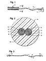
- the preferred embodiment of the ignition system cable of the present invention comprises cable portion 10 having first and second terminal contacts (not shown) at the left and right extremities, as viewed in FIG. 1. These contacts are housed within the ignition coil connector insulator 12 and spark plug connector insulator 14, both of which may be of conventional design well known to those skilled in the art.
- cable portion 10 may have a length between connector insulators 12 and 14 of less than a foot to several feet or more.
- Connector insulators 12 and 14 comprise rubber or rubber-like protective insulation which is shaped and otherwise designed to perform the insulation function and maintain the integrity of the connection in the particular ignition system in which it is employed.
- FIG. 1 The cutaway portions adjacent the center of FIG. 1 show a plurality of flexible ignition conductors adjacent the center which are two in number in the illustrated embodiment. The invention, however, is not necessarily limited thereto. Details of these ignition conductors are discussed in connection with FIGs. 2 and 3.
- electrical ignition system cable 10 comprises flexible ignition conductors 16 and 18, which in the illustrated embodiment are identical but need not be. They comprise inert core 20 comprising a multiplicity of elongated strands of glass and Kevlar fibers, the particular size and configuration thereof being well known to those skilled in the art. While the cross-sectional configuration of the electrically-inert center is shown as circular, such cross section may vary somewhat depending upon the manufacturing technique, whether the conductor is flexed, and the like.
- each of these wires 22 is sized so as to be individually electrically capable of communicating the ignition pulses to be carried by the wire.
- the flexible ignition conductors 16 and 18 are helically twisted about each other whereby wires 22 are in repeated or substantially continuous electrical contact along the respective lengths of each.
- wire 22 of conductors 16 and 18 are coated, continuously or at least partially with an electrically-conductive coating 24. This coating tends to stabilize the positioning of conductors 16 and 18 and may be formulated to otherwise assist in the manufacture of the cable particularly when attaching terminal contacts thereto.
- coating 24 comprises a conductive acrylic or a conductive latex or equivalent. Limited conductivity thereof is imparted by its carbon black content or other suitable material. While the inherent resistivity of the coating may be greater than the underlying wire, the conductivity is more than sufficient to establish a conductive path between the wires 22 in the event of a break or breaks therein or substantial increase in resistance thereof due to wire deterioration, partial rupture or the like. Accordingly, while spirally wound wires 22 are in electrical parallel relationship, they in effect provide a multiplicity of cross paths between each other throughout their entire length.
- the twisting of the conductors can be considered a "safety twist". As already indicated, this assures that electrical integrity is maintained despite one or more breaks in either or both of wires 22. Should portions of wires 22 be electrically segregated by breaks, the presence of such breaks may be detected by changes (increases) in resistance between the contacts during routine maintenance checks.
- Conductors 16 and 18 are housed in a flexible medium 26 to insulate and protect the conductors and otherwise impart an attractive and user-friendly appearance and configuration thereto.
- flexible insulating medium 26 may comprise a silicon rubber, EPDM insulating material or equivalent, which is preferably added by extrusion techniques.
- the flexible insulating medium 26 is opaque; optionally, it may be transparent or translucent, as already indicated.
- wires 16 and 18 are helically twisted along their entire length between ignition coil contact 28 and spark plug contact 30 which are housed within connector insulators 12 and 14 (FIG. 1), respectively.
- the configuration of contacts 28 and 30 may be of conventional design to match the particular installation requirements.
- the flexible ignition conductors 16 and 18 and flexible insulating medium 26 are substantially the same as in FIG. 2.
- Insulating medium 26, however, is radially narrower and is encased in a concentric, annular reenforcing braid 32 of suitable flexible material, e.g., braided fiberglass or other strengthening equivalent.
- a protective outer annular jacket or sheath 34 of flexible insulating material provides the external surface of cable 10.
- the outer annular jacket may also be added by extrusion techniques, resulting in a plurality of extrusion steps.
- Sheath 34 may comprise the same flexible insulating material as medium 26, e.g., silicon rubber, EPDM or equivalent polymeric material. It may, however, comprise other suitable media having desired physical and aesthetic properties. If sheath 34 and medium 26 comprise the same flexible material, the cables of FIGS. 2 and 4 are in effect identical except for the presence of reinforcing braid 32.
- the failure-resistant electrical ignition system cable of the present invention copes with shortcomings of prior art cables and provides greater reliability and performance without necessitating the use of costly or experimental materials or manufacturing techniques. It achieves various objects of the present invention as previously set forth.
Landscapes
- Ignition Installations For Internal Combustion Engines (AREA)
- Insulated Conductors (AREA)
- Communication Cables (AREA)
Applications Claiming Priority (3)
| Application Number | Priority Date | Filing Date | Title |
|---|---|---|---|
| US08/145,980 US5397860A (en) | 1993-10-29 | 1993-10-29 | Multiple-core electrical ignition system cable |
| PCT/US1994/012275 WO1995012205A1 (en) | 1993-10-29 | 1994-10-24 | Improved multiple-core electrical ignition system cable |
| US145980 | 2002-05-14 |
Publications (3)
| Publication Number | Publication Date |
|---|---|
| EP0725968A1 EP0725968A1 (en) | 1996-08-14 |
| EP0725968A4 EP0725968A4 (en) | 1997-05-14 |
| EP0725968B1 true EP0725968B1 (en) | 1998-12-30 |
Family
ID=22515409
Family Applications (1)
| Application Number | Title | Priority Date | Filing Date |
|---|---|---|---|
| EP95900432A Expired - Lifetime EP0725968B1 (en) | 1993-10-29 | 1994-10-24 | Improved multiple-core electrical ignition system cable |
Country Status (22)
| Country | Link |
|---|---|
| US (1) | US5397860A (enExample) |
| EP (1) | EP0725968B1 (enExample) |
| JP (1) | JP2778834B2 (enExample) |
| KR (1) | KR100222108B1 (enExample) |
| CN (1) | CN1044752C (enExample) |
| AU (1) | AU674112B2 (enExample) |
| BR (1) | BR9407921A (enExample) |
| CA (1) | CA2175233C (enExample) |
| CZ (1) | CZ123996A3 (enExample) |
| DE (1) | DE69415688T2 (enExample) |
| ES (1) | ES2128691T3 (enExample) |
| GR (1) | GR3029675T3 (enExample) |
| HU (1) | HUT75804A (enExample) |
| IL (1) | IL111326A0 (enExample) |
| LV (1) | LV11574B (enExample) |
| NO (1) | NO961704L (enExample) |
| NZ (1) | NZ275963A (enExample) |
| PL (1) | PL177814B1 (enExample) |
| SK (1) | SK55296A3 (enExample) |
| TW (1) | TW258817B (enExample) |
| WO (1) | WO1995012205A1 (enExample) |
| ZA (1) | ZA948066B (enExample) |
Families Citing this family (19)
| Publication number | Priority date | Publication date | Assignee | Title |
|---|---|---|---|---|
| US5644491A (en) * | 1994-01-31 | 1997-07-01 | Sendec Corporation | Self contained multi-function engine monitor and timer for providing engine running time, job time, service time and tachometer functions |
| US5593524A (en) * | 1994-11-14 | 1997-01-14 | Philips; Peter A. | Electrical cable reinforced with a longitudinally applied tape |
| US6559376B2 (en) * | 1996-09-30 | 2003-05-06 | Nology Engineering, Inc. | Combustion initiation device and method for tuning a combustion initiation device |
| JPH10188694A (ja) * | 1996-12-25 | 1998-07-21 | Sumitomo Wiring Syst Ltd | 巻線型雑音防止抵抗電線の製造装置および製造方法 |
| JP3414179B2 (ja) * | 1996-12-27 | 2003-06-09 | 住友電装株式会社 | 巻線型雑音防止抵抗電線 |
| US7331731B2 (en) * | 2002-09-05 | 2008-02-19 | Colgate-Palmolive Company | Oral care toothbrush |
| US7665451B2 (en) * | 2005-04-04 | 2010-02-23 | Joe Luk Mui Lam | Ignition apparatus |
| CA2609556A1 (en) | 2005-05-25 | 2006-11-30 | Biolase Technology, Inc. | Device having activated textured surfaces for treating oral tissue |
| TWI292692B (en) * | 2006-01-11 | 2008-01-11 | Delta Electronics Inc | Centrifugal fan and its stator structure and base structure |
| USD582456S1 (en) * | 2006-07-27 | 2008-12-09 | Robert Anthony Davies | Automobile ignition cable ducting |
| USD582454S1 (en) * | 2006-07-27 | 2008-12-09 | Robert Anthony Davies | Automobile ignition cable ducting |
| USD582455S1 (en) * | 2006-07-27 | 2008-12-09 | Robert Anthony Davies | Automobile ignition cable ducting |
| USD582452S1 (en) * | 2006-07-27 | 2008-12-09 | Robert Anthony Davies | Automobile ignition cable ducting |
| USD582457S1 (en) * | 2006-07-27 | 2008-12-09 | Robert Anthony Davies | Automobile ignition cable ducting |
| USD582451S1 (en) * | 2006-07-27 | 2008-12-09 | Robert Anthony Davies | Automobile ignition cable ducting |
| USD582453S1 (en) * | 2006-07-27 | 2008-12-09 | Robert Anthony Davies | Automobile ignition cable ducting |
| US9124083B2 (en) * | 2010-01-25 | 2015-09-01 | Apple Inc. | Compression molded cable structures and methods for making the same |
| BR202016005102U2 (pt) * | 2016-03-08 | 2017-03-28 | Casamayoú Antesana Genaro | cabos ecológicos de ignição para a diminuição da emissão de gases poluentes |
| CN108598733A (zh) * | 2018-04-12 | 2018-09-28 | 袁明磊 | 一种导线及点火烧嘴 |
Family Cites Families (22)
| Publication number | Priority date | Publication date | Assignee | Title |
|---|---|---|---|---|
| US534596A (en) * | 1895-02-19 | Electrical conductor | ||
| US2131066A (en) * | 1934-10-01 | 1938-09-27 | John A Obermaier | Sealed connecter |
| US2185944A (en) * | 1939-05-26 | 1940-01-02 | Holmes Willis Gerald | Fire-detecting cable |
| US2433081A (en) * | 1942-12-16 | 1947-12-23 | Howard M Wilkoff | Method of making ignition harness |
| US2438006A (en) * | 1944-06-05 | 1948-03-16 | Zenith Radio Corp | Electric cord |
| US2577077A (en) * | 1947-06-02 | 1951-12-04 | Surprenant Electrical Insulati | Buoyant tow and communication line |
| US3040284A (en) * | 1958-07-08 | 1962-06-19 | Conax Corp | Termination fitting for mineral-insulated metal-sheath cable |
| DE1813397A1 (de) * | 1968-12-07 | 1970-06-18 | Kabel Metallwerke Ghh | Anordnung zur Halterung eines oder mehrerer supraleitfaehiger Leiterstraenge im Innern eines tiefstgekuehlten Kabels |
| GB1335580A (en) * | 1970-03-20 | 1973-10-31 | Yazaki Corp | High frequency noise prevention cable |
| US3680027A (en) * | 1971-04-19 | 1972-07-25 | Avnet Inc | Ignition cable |
| US3894172A (en) * | 1973-11-06 | 1975-07-08 | Gen Cable Corp | Multicable telephone cable in a common sheath |
| US4514712A (en) * | 1975-02-13 | 1985-04-30 | Mcdougal John A | Ignition coil |
| DE7817735U1 (de) * | 1978-06-09 | 1979-02-22 | Siemens Ag, 1000 Berlin Und 8000 Muenchen | Zweiadrige, mantellose Leitung für Femmeldezwecke |
| US4378550A (en) * | 1980-10-24 | 1983-03-29 | Belden Corporation | Process for forming ignition cable core and product of the process |
| US4434320A (en) * | 1982-02-22 | 1984-02-28 | Eaton Corporation | Contractible conduit sealing connector |
| US4683349A (en) * | 1984-11-29 | 1987-07-28 | Norichika Takebe | Elastic electric cable |
| US4700171A (en) * | 1986-12-04 | 1987-10-13 | United Technologies Corporation | Ignition wire |
| JPS63168915A (ja) * | 1986-12-27 | 1988-07-12 | 住友電装株式会社 | 巻線型雑音防止抵抗電線の製造方法 |
| GB2213980B (en) * | 1987-12-24 | 1991-11-06 | Yazaki Corp | Cable |
| DE3936143A1 (de) * | 1988-12-15 | 1990-06-21 | Nachrichtentechnische Vertrieb | Verbessertes lautsprecherkabel |
| US5034719A (en) * | 1989-04-04 | 1991-07-23 | Prestolite Wire Corporation | Radio frequency interference suppression ignition cable having a semiconductive polyolefin conductive core |
| US5059938A (en) * | 1990-04-16 | 1991-10-22 | Prestolite Wire Corporation | Wire wound ignition cable and method for making same |
-
1993
- 1993-10-29 US US08/145,980 patent/US5397860A/en not_active Expired - Fee Related
-
1994
- 1994-10-14 ZA ZA948066A patent/ZA948066B/xx unknown
- 1994-10-18 IL IL11132694A patent/IL111326A0/xx unknown
- 1994-10-24 KR KR1019960702208A patent/KR100222108B1/ko not_active Expired - Fee Related
- 1994-10-24 BR BR9407921A patent/BR9407921A/pt not_active Application Discontinuation
- 1994-10-24 NZ NZ275963A patent/NZ275963A/en unknown
- 1994-10-24 EP EP95900432A patent/EP0725968B1/en not_active Expired - Lifetime
- 1994-10-24 SK SK552-96A patent/SK55296A3/sk unknown
- 1994-10-24 HU HU9601129A patent/HUT75804A/hu unknown
- 1994-10-24 AU AU81258/94A patent/AU674112B2/en not_active Ceased
- 1994-10-24 DE DE69415688T patent/DE69415688T2/de not_active Expired - Fee Related
- 1994-10-24 CA CA002175233A patent/CA2175233C/en not_active Expired - Fee Related
- 1994-10-24 CZ CZ961239A patent/CZ123996A3/cs unknown
- 1994-10-24 CN CN94194246A patent/CN1044752C/zh not_active Expired - Fee Related
- 1994-10-24 JP JP7512802A patent/JP2778834B2/ja not_active Expired - Fee Related
- 1994-10-24 ES ES95900432T patent/ES2128691T3/es not_active Expired - Lifetime
- 1994-10-24 PL PL94314310A patent/PL177814B1/pl unknown
- 1994-10-24 WO PCT/US1994/012275 patent/WO1995012205A1/en not_active Ceased
-
1995
- 1995-01-11 TW TW084100223A patent/TW258817B/zh not_active IP Right Cessation
-
1996
- 1996-04-26 NO NO961704A patent/NO961704L/no unknown
- 1996-04-29 LV LVP-96-132A patent/LV11574B/en unknown
-
1999
- 1999-03-12 GR GR990400759T patent/GR3029675T3/el unknown
Also Published As
| Publication number | Publication date |
|---|---|
| EP0725968A1 (en) | 1996-08-14 |
| LV11574B (en) | 1997-02-20 |
| PL177814B1 (pl) | 2000-01-31 |
| AU674112B2 (en) | 1996-12-05 |
| JPH09507112A (ja) | 1997-07-15 |
| CA2175233A1 (en) | 1995-05-04 |
| LV11574A (lv) | 1996-10-20 |
| BR9407921A (pt) | 1996-11-26 |
| DE69415688D1 (de) | 1999-02-11 |
| GR3029675T3 (en) | 1999-06-30 |
| JP2778834B2 (ja) | 1998-07-23 |
| NO961704D0 (no) | 1996-04-26 |
| SK55296A3 (en) | 1997-01-08 |
| ES2128691T3 (es) | 1999-05-16 |
| CA2175233C (en) | 2000-08-22 |
| ZA948066B (en) | 1995-06-06 |
| CN1135805A (zh) | 1996-11-13 |
| NZ275963A (en) | 1998-02-26 |
| PL314310A1 (en) | 1996-09-02 |
| EP0725968A4 (en) | 1997-05-14 |
| KR100222108B1 (ko) | 1999-10-01 |
| CZ123996A3 (en) | 1997-02-12 |
| NO961704L (no) | 1996-06-17 |
| AU8125894A (en) | 1995-05-22 |
| US5397860A (en) | 1995-03-14 |
| DE69415688T2 (de) | 1999-06-10 |
| WO1995012205A1 (en) | 1995-05-04 |
| CN1044752C (zh) | 1999-08-18 |
| IL111326A0 (en) | 1995-12-31 |
| HU9601129D0 (en) | 1996-07-29 |
| HUT75804A (en) | 1997-05-28 |
| TW258817B (enExample) | 1995-10-01 |
Similar Documents
| Publication | Publication Date | Title |
|---|---|---|
| EP0725968B1 (en) | Improved multiple-core electrical ignition system cable | |
| CA2719689C (en) | Metal sheathed cable assembly | |
| US20100218970A1 (en) | Cable | |
| CN1669096A (zh) | 屏蔽电缆、布线元件及信息装置 | |
| CS207711B2 (en) | Screened power cable | |
| US7145082B2 (en) | Flexible electrical line | |
| US20060011376A1 (en) | Multi-axial electrically conductive cable with multi-layered core and method of manufacture and use | |
| US6207902B1 (en) | Electrical wiring cable with color contrast abrasion wear indicator | |
| EP0373120A1 (en) | Coaxial cable and making method therefor | |
| US5796043A (en) | High-tension cable | |
| GB2046500A (en) | Electrical cables | |
| JP3445489B2 (ja) | 検知機能付きバイパスケーブル | |
| CN220962862U (zh) | 一种抗弯曲电缆 | |
| JP3728792B2 (ja) | 導電ケーブル | |
| CN213878433U (zh) | 一种用于车载通信系统的天线电缆 | |
| EP0089993B1 (en) | Metal screen for a power cable | |
| CN120642001A (zh) | 数据传输线缆和用于制造受屏蔽的数据传输线缆的方法 | |
| KR20230103144A (ko) | 고기능성 경량 전기 케이블 | |
| BR102023001057A2 (pt) | Cabo ethernet para aplicações automotivas | |
| JP2024086662A (ja) | 通信用電線 | |
| CN111524646A (zh) | 一种高可靠柔性抗扭低压电缆及其制作方法 | |
| EP1082794A1 (en) | Electrical wiring containment and protection system and method | |
| JPH04136818U (ja) | 耐油・耐薬品・耐摩耗・耐屈曲・可撓性ケーブル | |
| GB2327529A (en) | Fire-resistant electric cable |
Legal Events
| Date | Code | Title | Description |
|---|---|---|---|
| PUAI | Public reference made under article 153(3) epc to a published international application that has entered the european phase |
Free format text: ORIGINAL CODE: 0009012 |
|
| 17P | Request for examination filed |
Effective date: 19960520 |
|
| AK | Designated contracting states |
Kind code of ref document: A1 Designated state(s): DE ES FR GB GR IT |
|
| AX | Request for extension of the european patent |
Free format text: LT PAYMENT 960520;SI PAYMENT 960520 |
|
| RAX | Requested extension states of the european patent have changed |
Free format text: LT PAYMENT 960520;SI PAYMENT 960520 |
|
| A4 | Supplementary search report drawn up and despatched |
Effective date: 19970326 |
|
| AK | Designated contracting states |
Kind code of ref document: A4 Designated state(s): AT BE CH DE DK ES FR GB GR IE IT LI LU MC NL PT SE |
|
| 17Q | First examination report despatched |
Effective date: 19970728 |
|
| GRAG | Despatch of communication of intention to grant |
Free format text: ORIGINAL CODE: EPIDOS AGRA |
|
| GRAG | Despatch of communication of intention to grant |
Free format text: ORIGINAL CODE: EPIDOS AGRA |
|
| GRAG | Despatch of communication of intention to grant |
Free format text: ORIGINAL CODE: EPIDOS AGRA |
|
| GRAH | Despatch of communication of intention to grant a patent |
Free format text: ORIGINAL CODE: EPIDOS IGRA |
|
| GRAH | Despatch of communication of intention to grant a patent |
Free format text: ORIGINAL CODE: EPIDOS IGRA |
|
| GRAA | (expected) grant |
Free format text: ORIGINAL CODE: 0009210 |
|
| AK | Designated contracting states |
Kind code of ref document: B1 Designated state(s): DE ES FR GB GR IT |
|
| AX | Request for extension of the european patent |
Free format text: LT PAYMENT 960520;SI PAYMENT 960520 |
|
| LTIE | Lt: invalidation of european patent or patent extension | ||
| REF | Corresponds to: |
Ref document number: 69415688 Country of ref document: DE Date of ref document: 19990211 |
|
| ITF | It: translation for a ep patent filed | ||
| ET | Fr: translation filed | ||
| REG | Reference to a national code |
Ref country code: ES Ref legal event code: FG2A Ref document number: 2128691 Country of ref document: ES Kind code of ref document: T3 |
|
| PLBE | No opposition filed within time limit |
Free format text: ORIGINAL CODE: 0009261 |
|
| STAA | Information on the status of an ep patent application or granted ep patent |
Free format text: STATUS: NO OPPOSITION FILED WITHIN TIME LIMIT |
|
| 26N | No opposition filed | ||
| REG | Reference to a national code |
Ref country code: GB Ref legal event code: IF02 |
|
| REG | Reference to a national code |
Ref country code: GB Ref legal event code: 732E |
|
| REG | Reference to a national code |
Ref country code: FR Ref legal event code: TP |
|
| PGFP | Annual fee paid to national office [announced via postgrant information from national office to epo] |
Ref country code: GR Payment date: 20030813 Year of fee payment: 10 |
|
| PGFP | Annual fee paid to national office [announced via postgrant information from national office to epo] |
Ref country code: ES Payment date: 20030827 Year of fee payment: 10 |
|
| PGFP | Annual fee paid to national office [announced via postgrant information from national office to epo] |
Ref country code: GB Payment date: 20031014 Year of fee payment: 10 |
|
| PGFP | Annual fee paid to national office [announced via postgrant information from national office to epo] |
Ref country code: FR Payment date: 20031021 Year of fee payment: 10 |
|
| PGFP | Annual fee paid to national office [announced via postgrant information from national office to epo] |
Ref country code: DE Payment date: 20031025 Year of fee payment: 10 |
|
| REG | Reference to a national code |
Ref country code: ES Ref legal event code: PC2A |
|
| PG25 | Lapsed in a contracting state [announced via postgrant information from national office to epo] |
Ref country code: GB Free format text: LAPSE BECAUSE OF NON-PAYMENT OF DUE FEES Effective date: 20041024 |
|
| PG25 | Lapsed in a contracting state [announced via postgrant information from national office to epo] |
Ref country code: ES Free format text: LAPSE BECAUSE OF NON-PAYMENT OF DUE FEES Effective date: 20041025 |
|
| PG25 | Lapsed in a contracting state [announced via postgrant information from national office to epo] |
Ref country code: DE Free format text: LAPSE BECAUSE OF NON-PAYMENT OF DUE FEES Effective date: 20050503 |
|
| PG25 | Lapsed in a contracting state [announced via postgrant information from national office to epo] |
Ref country code: GR Free format text: LAPSE BECAUSE OF NON-PAYMENT OF DUE FEES Effective date: 20050504 |
|
| GBPC | Gb: european patent ceased through non-payment of renewal fee |
Effective date: 20041024 |
|
| PG25 | Lapsed in a contracting state [announced via postgrant information from national office to epo] |
Ref country code: FR Free format text: LAPSE BECAUSE OF NON-PAYMENT OF DUE FEES Effective date: 20050630 |
|
| REG | Reference to a national code |
Ref country code: FR Ref legal event code: ST |
|
| PG25 | Lapsed in a contracting state [announced via postgrant information from national office to epo] |
Ref country code: IT Free format text: LAPSE BECAUSE OF NON-PAYMENT OF DUE FEES;WARNING: LAPSES OF ITALIAN PATENTS WITH EFFECTIVE DATE BEFORE 2007 MAY HAVE OCCURRED AT ANY TIME BEFORE 2007. THE CORRECT EFFECTIVE DATE MAY BE DIFFERENT FROM THE ONE RECORDED. Effective date: 20051024 |
|
| REG | Reference to a national code |
Ref country code: ES Ref legal event code: FD2A Effective date: 20041025 |