EP0725885B1 - A roller blind, particularly for use as blackout shade - Google Patents
A roller blind, particularly for use as blackout shade Download PDFInfo
- Publication number
- EP0725885B1 EP0725885B1 EP93907811A EP93907811A EP0725885B1 EP 0725885 B1 EP0725885 B1 EP 0725885B1 EP 93907811 A EP93907811 A EP 93907811A EP 93907811 A EP93907811 A EP 93907811A EP 0725885 B1 EP0725885 B1 EP 0725885B1
- Authority
- EP
- European Patent Office
- Prior art keywords
- cord
- bottom bar
- bar
- roller
- blind
- Prior art date
- Legal status (The legal status is an assumption and is not a legal conclusion. Google has not performed a legal analysis and makes no representation as to the accuracy of the status listed.)
- Expired - Lifetime
Links
Images

Classifications
-
- E—FIXED CONSTRUCTIONS
- E06—DOORS, WINDOWS, SHUTTERS, OR ROLLER BLINDS IN GENERAL; LADDERS
- E06B—FIXED OR MOVABLE CLOSURES FOR OPENINGS IN BUILDINGS, VEHICLES, FENCES OR LIKE ENCLOSURES IN GENERAL, e.g. DOORS, WINDOWS, BLINDS, GATES
- E06B9/00—Screening or protective devices for wall or similar openings, with or without operating or securing mechanisms; Closures of similar construction
- E06B9/56—Operating, guiding or securing devices or arrangements for roll-type closures; Spring drums; Tape drums; Counterweighting arrangements therefor
- E06B9/68—Operating devices or mechanisms, e.g. with electric drive
-
- E—FIXED CONSTRUCTIONS
- E06—DOORS, WINDOWS, SHUTTERS, OR ROLLER BLINDS IN GENERAL; LADDERS
- E06B—FIXED OR MOVABLE CLOSURES FOR OPENINGS IN BUILDINGS, VEHICLES, FENCES OR LIKE ENCLOSURES IN GENERAL, e.g. DOORS, WINDOWS, BLINDS, GATES
- E06B9/00—Screening or protective devices for wall or similar openings, with or without operating or securing mechanisms; Closures of similar construction
- E06B9/24—Screens or other constructions affording protection against light, especially against sunshine; Similar screens for privacy or appearance; Slat blinds
- E06B9/40—Roller blinds
-
- E—FIXED CONSTRUCTIONS
- E06—DOORS, WINDOWS, SHUTTERS, OR ROLLER BLINDS IN GENERAL; LADDERS
- E06B—FIXED OR MOVABLE CLOSURES FOR OPENINGS IN BUILDINGS, VEHICLES, FENCES OR LIKE ENCLOSURES IN GENERAL, e.g. DOORS, WINDOWS, BLINDS, GATES
- E06B9/00—Screening or protective devices for wall or similar openings, with or without operating or securing mechanisms; Closures of similar construction
- E06B9/56—Operating, guiding or securing devices or arrangements for roll-type closures; Spring drums; Tape drums; Counterweighting arrangements therefor
- E06B9/58—Guiding devices
- E06B2009/583—Cords or cables
Definitions
- the invention relates to a roller blind, particularly for use as blackout shade, comprising a spring-biassed roller bar designed to be mounted at the top of a window opening and a blind rolled on the roller bar and having along its lateral edges guide members guided in tracks provided in guide rails disposed at both sides of the window opening, a bottom bar for the blind being likewise provided, at both ends, with guide means engaging guideways in said guide rails, and being further controlled by means of a cord arrangement with a cord which from a fixture means at the bottom of one guide rail is passed through the part of said guide rail positioned beneath the bottom bar, the bottom bar itself, and the part of the other guide rail positioned above the bottom bar, to a fixture means at the top of the other guide rail.
- roller blinds to be mounted in connection with skylights in inclined roofs use is made of a spring-biassed roller bar ensuring that the blind is kept tight in all positions between the completely raised position and the maximum drawn bottom position.
- Such comparatively simple side rails are, however, not usable in connection with blinds for blackout shades of the above mentioned type, in which the side guide rails must be designed so as to ensure light-proofness at the edges of the window.
- the roller bar which is most frequently enclosed in a cassette, as well as the bottom bar with appropriate sealing strips.
- a roller blind of the above mentioned type is characterized in that a brake device for retaining the bottom bar in an arbitrary position against the effect of said spring bias includes a friction member in the form of at least one reversing member for the cord, firmly mounted in the bottom bar and acting on the cord to provide a total change of its direction of substantially 360°; a device for tightening the cord being provided in association with one of said fixture means.
- the means for parallel guidance include a supplementary cord arrangement passed through the guide rails and the bottom part, in reverse mounting in relation to said cord.
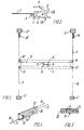
- a spring-biassed roller bar In the roller blind for a blackout shade illustrated in Fig. 1 a spring-biassed roller bar, not shown in detail, is enclosed in a cassette 1 mounted atop the window opening in such a manner that it fits lightproof to the window main frame.
- a blind 2 of lightproof material is rolled on the roller bar.
- Guide members e.g. in the form of semispherical buttons 3 which, as illustrated in Fig. 2, are guided in tracks 4 provided in guide rails 5 and 6 disposed at either side of the window opening are in a manner known per se spaced apart along both of the lateral edges of the blind 2, at distances which may for instance vary from 3 to 10 cm.
- the blind is fastened in a bottom bar 7 having guide means at the ends, likewise engaging guideways 8 in the guide rails 5 and 6.
- said arresting mechanism includes a brake device of which an embodiment is illustrated in Fig. 3.
- the brake device comprises a mirror-inverted arrangement of two cords 9 and 10, of which the cord 9 shown in solid lines in the figure is passed from a fixture means 11 at the bottom of the left guide rail 5 up through a track 12 in this guide rail, shown in Fig. 2, and over a roller or pin 13 through the bottom bar 7 in which a friction member acting on the cord in the illustrated embodiment includes two pins 14 and 15 around which the cord is passed in S-shape and from there further on to the opposite end of the bottom bar 7, from where it is passed over a roller or pin 16 through the part of the guideway 12 positioned above the bottom bar 7 of the right slotted guide 6 to a fixture means 17 at the top of said slotted guide.
- the fixture means 11 and 17 may appropriately be provided in retaining means, e.g. a plastic plug, that may be inserted at the bottom of the guide rail 5 and a clip-like plug that may be mounted at the top of the guide rail 6. With the view of tightening the cord 9, the upper end thereof is connected with a tension spring 18 mounted in the fixture means 17.
- retaining means e.g. a plastic plug, that may be inserted at the bottom of the guide rail 5 and a clip-like plug that may be mounted at the top of the guide rail 6.
- the cord 10 is mirror-inverted in relation to the cord 9, and the fixture and cord guiding means for this cord have the same reference numerals as the corresponding members for the cord 9, but further marked with an apostrophe.
- This double cord arrangement provides for obtaining both an effective braking capable of retaining the bottom bar 7 arrested in an arbitrary position between the top and the bottom, and an accurate parallel guidance of the bottom bar 7 in relation to the roller bar mounted in the cassette 1.
- the braking effect is caused by the S-shaped twisting of the cords 9 and 10, respectively, around the pins 14, 15 and 14', 15', respectively, the friction between the cords and said pins and the tension exterted by the springs 18 and 18'.
- the illustrated S-shaped cord path represents only an embodiment, because reversal of direction may be effected by means of a single pin around which the cord may be passed in an entwinement of 360°. This, however, involves the inconvenience that the cord when running off the pin will slide against itself, thereby being exposed to more wear than in the illustrated example with two entwinements of 180°.
- the braking force may be controlled by choosing a larger number of pins, other angle changes of the cord entwinement round the individual pins and stronger or weaker springs. By these means the braking force is easily dimensioned so that the bottom bar may be safely retained in arbitrary positions.
- the embodiment illustrated in Fig. 3 allows the cords to stand far more than 10,000 raisings and drawings of the blind with no substantial wear and deterioration of the braking effect.
- the cord inverting arrangement in the bottom bar may advantageously be provided in that the pins 14, 15 and 14', 15', respectively, are mounted in a common holder 19 design for being fixed in the bottom bar 7, as illustrated in Figs 4 and 5.
- the cord paths for the cords 9 and 10 are separated by a partition wall 20 and in contradiction to the schematical illustration in Fig. 3 the reversal of both cord paths is provided by means of two common pins 21 and 22 extending through the holder 19 on both sides of the partition wall 20.
- the invention is not restricted to the illustrated design of the brake device with an arrangement of reversal for the cords, the braking force being achieved with other designs of the friction members acting on the cords.
- the applicability of the invention is not restricted to blinds for blackout shades but may include any form of roller blind with a constantly spring-biassed blind for which it is desired to have the possibility of arresting in arbitrary positions.
Abstract
Description
Claims (6)
- A roller blind, particularly for use as blackout shade, comprising a spring-biassed roller bar designed to be mounted at the top of a window opening and a blind rolled on the roller bar and having along its lateral edges guide members (3) guided in tracks (4) provided in guide rails (5, 6) disposed at both sides of the window opening, a bottom bar (7) for the blind (2) being likewise provided, at both ends, with guide means engaging guideways (8) in said guide rails (5,6), and being further controlled by means of a cord arrangement with a cord (9, 10) which from a fixture means (11, 11') at the bottom of one guide rail (5, 6) is passed through the part of said guide rail positioned beneath the bottom bar (7), the bottom bar (7) itself, and the part of the other guide rail (6, 5) positioned above the bottom bar (7), to a fixture means at the top of the other guide rail,
characterized in that a brake device for retaining the bottom bar (7) in an arbitrary position against the effect of said spring bias includes a friction member in the form of at least one reversing member (14, 15, 14', 15') for the cord, firmly mounted in the bottom bar (7) and acting on the cord to provide a total change of its direction of substantially 360°; a device (18, 18') for tightening the cord (9, 10) being provided in association with one of said fixture means. - A roller blind as claimed in claim 1,
characterized in that said reversing member comprises two pins (14, 15, 14', 15') disposed in the bottom bar and over which the cord (9, 10) is passed in S-shape. - A roller blind as claimed in claim 2,
characterized in that the two pins (14, 15, 14', 15') are provided in a common holder (19) to be mounted in the bottom bar (7). - A roller blind as claimed in any of the preceding claims, characterized in that said fixture means (11, 17, 11', 17') for the cord (9, 10) are provided in retaining means to be inserted in respective ends of the two guide rails (5, 6).
- A roller blind as claimed in claim 4,
characterized in that the cord tightening member (17, 17') consists of a tension spring (18, 18') mounted in one of said fixture means (17, 17') and connected with the actual cord end. - A roller blind as claimed in any of the preceding claims, in which the cord arrangement for ensuring parallel guidance of the bottom bar (7) in relation to the roller bar includes two cords (9, 10) passed through the guide rails (5, 6) and the bottom bar (7) in reverse mounting,
characterized in that said holder (19) as the friction member for both cords (9, 10) includes two common reversing pins (21, 22), and that the holder is provided with a partition wall (20) for separating the two cord paths.
Applications Claiming Priority (4)
| Application Number | Priority Date | Filing Date | Title |
|---|---|---|---|
| DK32292 | 1992-03-11 | ||
| DK322/92 | 1992-03-11 | ||
| DK92322A DK32292D0 (en) | 1992-03-11 | 1992-03-11 | ROLLERGARDIN, NAME FOR DARKNESS |
| PCT/DK1993/000090 WO1993018270A1 (en) | 1992-03-11 | 1993-03-10 | A roller blind, particularly for use as blackout shade |
Publications (2)
| Publication Number | Publication Date |
|---|---|
| EP0725885A1 EP0725885A1 (en) | 1996-08-14 |
| EP0725885B1 true EP0725885B1 (en) | 1998-12-02 |
Family
ID=8092245
Family Applications (1)
| Application Number | Title | Priority Date | Filing Date |
|---|---|---|---|
| EP93907811A Expired - Lifetime EP0725885B1 (en) | 1992-03-11 | 1993-03-10 | A roller blind, particularly for use as blackout shade |
Country Status (17)
| Country | Link |
|---|---|
| US (1) | US5535806A (en) |
| EP (1) | EP0725885B1 (en) |
| JP (1) | JP3348229B2 (en) |
| AT (1) | ATE174101T1 (en) |
| AU (1) | AU661578B2 (en) |
| CA (1) | CA2131314C (en) |
| CZ (1) | CZ285454B6 (en) |
| DE (1) | DE69322416T2 (en) |
| DK (1) | DK32292D0 (en) |
| ES (1) | ES2125333T3 (en) |
| FI (1) | FI100060B (en) |
| HU (1) | HU213153B (en) |
| NO (1) | NO301347B1 (en) |
| NZ (1) | NZ251322A (en) |
| PL (1) | PL171448B1 (en) |
| SK (1) | SK280957B6 (en) |
| WO (1) | WO1993018270A1 (en) |
Families Citing this family (31)
| Publication number | Priority date | Publication date | Assignee | Title |
|---|---|---|---|---|
| US5566736A (en) * | 1995-11-13 | 1996-10-22 | Crider; Grant W. | Sealable curtain |
| US5671790A (en) * | 1996-01-24 | 1997-09-30 | V. Kann Rasmussen Industri A/S | Screening device for a wall opening |
| DK9097A (en) | 1997-01-24 | 1998-07-25 | Rasmussen Kann Ind As | Universal mounting and parallel guiding arrangement for a window guard device |
| DE19750713C1 (en) * | 1997-11-15 | 1998-12-17 | Webasto Karosseriesysteme | Cover for roof of motor vehicle |
| DK176031B1 (en) * | 1998-04-17 | 2006-01-02 | Vkr Holding As | Ball stop designed as a window guard arresting device |
| DK176092B1 (en) * | 1998-07-21 | 2006-05-22 | Vkr Holding As | Shielding arrangement for a window as well as universal mounting and parallel guiding arrangement for a window shading device |
| US6138739A (en) * | 1999-01-15 | 2000-10-31 | Grant W. Crider | Portal covering |
| DK174572B1 (en) * | 1999-01-25 | 2003-06-23 | Vkr Holding As | A screening device |
| US6338378B1 (en) * | 1999-04-12 | 2002-01-15 | Vkr Holdings A/S | Window screening arrangement with a braking device |
| US6691760B1 (en) * | 2002-01-15 | 2004-02-17 | Comfortex Corporation | Lift cord tensioning device |
| ATE477394T1 (en) * | 2002-06-14 | 2010-08-15 | Vkr Holding As | MOTOR-DRIVEN SHIELDING DEVICE AND USE THEREOF |
| PL214238B1 (en) * | 2002-12-09 | 2013-07-31 | Vkr Holding As | Screening device and method for mounting such device |
| US20060196612A1 (en) * | 2005-03-03 | 2006-09-07 | Springs Window Fashions Lp | Bottom up top down cordless shade |
| GB2423328B (en) | 2005-04-09 | 2007-02-28 | Louver Lite Ltd | Window blind system |
| TWI463061B (en) * | 2006-06-09 | 2014-12-01 | Hunter Douglas Ind Bv | Covering and component parts thereof |
| US20080000597A1 (en) * | 2006-06-19 | 2008-01-03 | Matthew Watford | Light restricting system and method |
| US8056601B2 (en) * | 2008-03-12 | 2011-11-15 | Lutron Electronics Co., Inc. | Self-contained tensioned roller shade system |
| US8256492B2 (en) * | 2011-01-13 | 2012-09-04 | Macauto Industrial Co., Ltd. | Frame-mounted sunshade device |
| US9482048B2 (en) | 2011-03-07 | 2016-11-01 | Hunter Douglas, Inc. | Control for movable rail |
| CN102409956A (en) * | 2011-11-01 | 2012-04-11 | 上海阳毅新型门窗有限公司 | Door and window structure with external roller blind |
| US9303450B2 (en) * | 2012-05-10 | 2016-04-05 | Hunter Douglas Inc. | Parallel bar cording for movable rails |
| US9267325B2 (en) | 2013-10-02 | 2016-02-23 | The Boeing Company | Airplane shade handle and sliding mechanism |
| US9115532B1 (en) | 2014-03-21 | 2015-08-25 | Brand Awareness, Inc. | Light blocking side valance for window treatments |
| CN204552578U (en) * | 2015-03-27 | 2015-08-12 | 太仓敬富塑胶制品有限公司 | Without the reinforced resistance adjustment device of exposed pulling rod curtain |
| DE202017103279U1 (en) | 2017-05-31 | 2018-09-03 | M.A.C.'s Holding Gmbh | Protective device, in particular as a roof window insect screen |
| US10730367B2 (en) | 2017-06-27 | 2020-08-04 | Bauer Products, Inc. | Vent shade assembly |
| US10596883B2 (en) * | 2017-06-27 | 2020-03-24 | Bauer Products, Inc. | Vent shade assembly |
| US11377904B2 (en) | 2018-12-14 | 2022-07-05 | Crestron Electronics, Inc. | Roller shade for non-rectangular windows |
| US11053732B2 (en) | 2019-05-28 | 2021-07-06 | Crestron Electronics, Inc. | Skylight roller shade alignment mechanism |
| US11053731B2 (en) | 2019-05-28 | 2021-07-06 | Crestron Electronics, Inc. | Skylight roller shade with a cable cone indexing mechanism |
| EP4031741A4 (en) * | 2019-09-17 | 2023-11-08 | Commercialisation Express Pty Ltd | Blockout blind system |
Family Cites Families (17)
| Publication number | Priority date | Publication date | Assignee | Title |
|---|---|---|---|---|
| US577842A (en) * | 1897-03-02 | Curtain-holding device | ||
| US564682A (en) * | 1896-07-28 | Curtain-guide | ||
| US560133A (en) * | 1896-05-12 | Fixture for window-shades | ||
| US794937A (en) * | 1903-09-12 | 1905-07-18 | Curtain Supply Co | Shade-holding device. |
| US785806A (en) * | 1904-06-13 | 1905-03-28 | Curtain Supply Co | Curtain-fixture. |
| US1815551A (en) * | 1929-02-02 | 1931-07-21 | Harry W Dunn | Dark room shade construction |
| US2243771A (en) * | 1938-09-29 | 1941-05-27 | Harry B Lawson | Window closure or similar fitting |
| US2780283A (en) * | 1952-12-23 | 1957-02-05 | Wasserman Max | Skylight construction |
| US4473101A (en) * | 1980-08-13 | 1984-09-25 | Verosol B.V. | Sun blind |
| DE8407488U1 (en) * | 1984-03-12 | 1984-08-02 | Warema Renkhoff Gmbh & Co Kg, 8772 Marktheidenfeld | ROLLER FOR ROOF AREA WINDOW |
| US4574864A (en) * | 1984-09-13 | 1986-03-11 | Tse Brian H | Vertically positioning window shading system |
| US4762160A (en) * | 1986-08-22 | 1988-08-09 | Bechtold Stephen K | Skylight shade assembly |
| FR2615240A1 (en) * | 1987-05-14 | 1988-11-18 | Farnier & Penin | Blind device balanced by cables |
| ES2012620A6 (en) * | 1989-01-30 | 1990-04-01 | Lon Jesne Sa | Roller-type door with rapid displacement |
| US5088543A (en) * | 1990-06-04 | 1992-02-18 | Bilbrey Paul J | Skylight shade |
| FR2663675B1 (en) * | 1990-06-21 | 1998-02-20 | Cros Store Zenith | DEVICE FOR WINDING AND UNWINDING A CANVAS. |
| CH682247A5 (en) * | 1991-06-21 | 1993-08-13 | Sonne Regen Ag |
-
1992
- 1992-03-11 DK DK92322A patent/DK32292D0/en not_active Application Discontinuation
-
1993
- 1993-03-10 AT AT93907811T patent/ATE174101T1/en not_active IP Right Cessation
- 1993-03-10 EP EP93907811A patent/EP0725885B1/en not_active Expired - Lifetime
- 1993-03-10 CZ CZ942196A patent/CZ285454B6/en not_active IP Right Cessation
- 1993-03-10 SK SK1079-94A patent/SK280957B6/en unknown
- 1993-03-10 US US08/290,958 patent/US5535806A/en not_active Expired - Lifetime
- 1993-03-10 DE DE69322416T patent/DE69322416T2/en not_active Expired - Lifetime
- 1993-03-10 CA CA002131314A patent/CA2131314C/en not_active Expired - Fee Related
- 1993-03-10 HU HU9402533A patent/HU213153B/en not_active IP Right Cessation
- 1993-03-10 NZ NZ251322A patent/NZ251322A/en unknown
- 1993-03-10 AU AU38881/93A patent/AU661578B2/en not_active Ceased
- 1993-03-10 WO PCT/DK1993/000090 patent/WO1993018270A1/en active IP Right Grant
- 1993-03-10 JP JP51526893A patent/JP3348229B2/en not_active Expired - Fee Related
- 1993-03-10 PL PL93305162A patent/PL171448B1/en not_active IP Right Cessation
- 1993-03-10 ES ES93907811T patent/ES2125333T3/en not_active Expired - Lifetime
-
1994
- 1994-09-09 FI FI944156A patent/FI100060B/en not_active IP Right Cessation
- 1994-09-09 NO NO943331A patent/NO301347B1/en not_active IP Right Cessation
Also Published As
| Publication number | Publication date |
|---|---|
| PL171448B1 (en) | 1997-04-30 |
| NO301347B1 (en) | 1997-10-13 |
| CA2131314C (en) | 2002-12-31 |
| NO943331D0 (en) | 1994-09-09 |
| SK107994A3 (en) | 1995-02-08 |
| HUT67645A (en) | 1995-04-28 |
| DE69322416T2 (en) | 1999-07-08 |
| DE69322416D1 (en) | 1999-01-14 |
| NO943331L (en) | 1994-09-09 |
| NZ251322A (en) | 1996-02-27 |
| SK280957B6 (en) | 2000-10-09 |
| AU661578B2 (en) | 1995-07-27 |
| DK32292D0 (en) | 1992-03-11 |
| EP0725885A1 (en) | 1996-08-14 |
| WO1993018270A1 (en) | 1993-09-16 |
| JP3348229B2 (en) | 2002-11-20 |
| FI944156A0 (en) | 1994-09-09 |
| ATE174101T1 (en) | 1998-12-15 |
| JPH07504470A (en) | 1995-05-18 |
| CZ285454B6 (en) | 1999-08-11 |
| HU213153B (en) | 1997-02-28 |
| FI100060B (en) | 1997-09-15 |
| FI944156A (en) | 1994-09-09 |
| US5535806A (en) | 1996-07-16 |
| CZ219694A3 (en) | 1995-02-15 |
| HU9402533D0 (en) | 1994-11-28 |
| ES2125333T3 (en) | 1999-03-01 |
| AU3888193A (en) | 1993-10-05 |
| CA2131314A1 (en) | 1993-09-16 |
Similar Documents
| Publication | Publication Date | Title |
|---|---|---|
| EP0725885B1 (en) | A roller blind, particularly for use as blackout shade | |
| US4862941A (en) | Vertical shade assembly | |
| AU719794B2 (en) | Guidance device for a flexible curtain door | |
| US5479979A (en) | Screen device | |
| US5113922A (en) | Venetian blind assembly for a window in an inclined roof | |
| US6035920A (en) | Screening arrangement | |
| EP0534261A3 (en) | Blind, in particular for a non-rectangular (glass) area | |
| PL333105A1 (en) | Reeled window shutter | |
| WO1990005828A1 (en) | Roll-up door | |
| EP0959221A1 (en) | Quick-installation mosquito net | |
| GB2276650A (en) | Tassel weight |
Legal Events
| Date | Code | Title | Description |
|---|---|---|---|
| PUAI | Public reference made under article 153(3) epc to a published international application that has entered the european phase |
Free format text: ORIGINAL CODE: 0009012 |
|
| 17P | Request for examination filed |
Effective date: 19940829 |
|
| AK | Designated contracting states |
Kind code of ref document: A1 Designated state(s): AT BE CH DE DK ES FR GB GR IE IT LI LU MC NL PT SE |
|
| 17Q | First examination report despatched |
Effective date: 19970711 |
|
| GRAG | Despatch of communication of intention to grant |
Free format text: ORIGINAL CODE: EPIDOS AGRA |
|
| GRAG | Despatch of communication of intention to grant |
Free format text: ORIGINAL CODE: EPIDOS AGRA |
|
| GRAG | Despatch of communication of intention to grant |
Free format text: ORIGINAL CODE: EPIDOS AGRA |
|
| GRAH | Despatch of communication of intention to grant a patent |
Free format text: ORIGINAL CODE: EPIDOS IGRA |
|
| GRAH | Despatch of communication of intention to grant a patent |
Free format text: ORIGINAL CODE: EPIDOS IGRA |
|
| RAP1 | Party data changed (applicant data changed or rights of an application transferred) |
Owner name: VELUX INDUSTRI A/S |
|
| GRAA | (expected) grant |
Free format text: ORIGINAL CODE: 0009210 |
|
| AK | Designated contracting states |
Kind code of ref document: B1 Designated state(s): AT BE CH DE DK ES FR GB GR IE IT LI LU MC NL PT SE |
|
| PG25 | Lapsed in a contracting state [announced via postgrant information from national office to epo] |
Ref country code: GR Free format text: LAPSE BECAUSE OF NON-PAYMENT OF DUE FEES Effective date: 19981202 |
|
| REF | Corresponds to: |
Ref document number: 174101 Country of ref document: AT Date of ref document: 19981215 Kind code of ref document: T |
|
| REG | Reference to a national code |
Ref country code: CH Ref legal event code: EP |
|
| REF | Corresponds to: |
Ref document number: 69322416 Country of ref document: DE Date of ref document: 19990114 |
|
| REG | Reference to a national code |
Ref country code: IE Ref legal event code: FG4D |
|
| ITF | It: translation for a ep patent filed |
Owner name: ING. A. GIAMBROCONO & C. S.R.L. |
|
| ET | Fr: translation filed | ||
| REG | Reference to a national code |
Ref country code: CH Ref legal event code: NV Representative=s name: TROESCH SCHEIDEGGER WERNER AG |
|
| REG | Reference to a national code |
Ref country code: ES Ref legal event code: FG2A Ref document number: 2125333 Country of ref document: ES Kind code of ref document: T3 |
|
| PG25 | Lapsed in a contracting state [announced via postgrant information from national office to epo] |
Ref country code: SE Free format text: LAPSE BECAUSE OF FAILURE TO SUBMIT A TRANSLATION OF THE DESCRIPTION OR TO PAY THE FEE WITHIN THE PRESCRIBED TIME-LIMIT Effective date: 19990302 Ref country code: PT Free format text: LAPSE BECAUSE OF FAILURE TO SUBMIT A TRANSLATION OF THE DESCRIPTION OR TO PAY THE FEE WITHIN THE PRESCRIBED TIME-LIMIT Effective date: 19990302 Ref country code: DK Free format text: LAPSE BECAUSE OF FAILURE TO SUBMIT A TRANSLATION OF THE DESCRIPTION OR TO PAY THE FEE WITHIN THE PRESCRIBED TIME-LIMIT Effective date: 19990302 |
|
| PG25 | Lapsed in a contracting state [announced via postgrant information from national office to epo] |
Ref country code: LU Free format text: LAPSE BECAUSE OF NON-PAYMENT OF DUE FEES Effective date: 19990310 Ref country code: IE Free format text: LAPSE BECAUSE OF NON-PAYMENT OF DUE FEES Effective date: 19990310 |
|
| PG25 | Lapsed in a contracting state [announced via postgrant information from national office to epo] |
Ref country code: MC Free format text: LAPSE BECAUSE OF NON-PAYMENT OF DUE FEES Effective date: 19990930 |
|
| PLBE | No opposition filed within time limit |
Free format text: ORIGINAL CODE: 0009261 |
|
| STAA | Information on the status of an ep patent application or granted ep patent |
Free format text: STATUS: NO OPPOSITION FILED WITHIN TIME LIMIT |
|
| 26N | No opposition filed | ||
| REG | Reference to a national code |
Ref country code: IE Ref legal event code: MM4A |
|
| REG | Reference to a national code |
Ref country code: CH Ref legal event code: PFA Free format text: VELUX INDUSTRI A/S TRANSFER- VKR HOLDING A/S |
|
| NLT1 | Nl: modifications of names registered in virtue of documents presented to the patent office pursuant to art. 16 a, paragraph 1 |
Owner name: VKR HOLDING A/S |
|
| REG | Reference to a national code |
Ref country code: FR Ref legal event code: CD |
|
| REG | Reference to a national code |
Ref country code: GB Ref legal event code: IF02 |
|
| PGFP | Annual fee paid to national office [announced via postgrant information from national office to epo] |
Ref country code: AT Payment date: 20040308 Year of fee payment: 12 |
|
| PGFP | Annual fee paid to national office [announced via postgrant information from national office to epo] |
Ref country code: BE Payment date: 20040309 Year of fee payment: 12 |
|
| PGFP | Annual fee paid to national office [announced via postgrant information from national office to epo] |
Ref country code: CH Payment date: 20040311 Year of fee payment: 12 |
|
| PGFP | Annual fee paid to national office [announced via postgrant information from national office to epo] |
Ref country code: ES Payment date: 20050302 Year of fee payment: 13 |
|
| PGFP | Annual fee paid to national office [announced via postgrant information from national office to epo] |
Ref country code: GB Payment date: 20050308 Year of fee payment: 13 |
|
| PG25 | Lapsed in a contracting state [announced via postgrant information from national office to epo] |
Ref country code: AT Free format text: LAPSE BECAUSE OF NON-PAYMENT OF DUE FEES Effective date: 20050310 |
|
| PG25 | Lapsed in a contracting state [announced via postgrant information from national office to epo] |
Ref country code: LI Free format text: LAPSE BECAUSE OF NON-PAYMENT OF DUE FEES Effective date: 20050331 Ref country code: CH Free format text: LAPSE BECAUSE OF NON-PAYMENT OF DUE FEES Effective date: 20050331 Ref country code: BE Free format text: LAPSE BECAUSE OF NON-PAYMENT OF DUE FEES Effective date: 20050331 |
|
| BERE | Be: lapsed |
Owner name: *VKR HOLDING A/S Effective date: 20050331 |
|
| REG | Reference to a national code |
Ref country code: CH Ref legal event code: PL |
|
| PG25 | Lapsed in a contracting state [announced via postgrant information from national office to epo] |
Ref country code: GB Free format text: LAPSE BECAUSE OF NON-PAYMENT OF DUE FEES Effective date: 20060310 |
|
| PG25 | Lapsed in a contracting state [announced via postgrant information from national office to epo] |
Ref country code: ES Free format text: LAPSE BECAUSE OF NON-PAYMENT OF DUE FEES Effective date: 20060311 |
|
| GBPC | Gb: european patent ceased through non-payment of renewal fee |
Effective date: 20060310 |
|
| REG | Reference to a national code |
Ref country code: ES Ref legal event code: FD2A Effective date: 20060311 |
|
| BERE | Be: lapsed |
Owner name: *VKR HOLDING A/S Effective date: 20050331 |
|
| PGFP | Annual fee paid to national office [announced via postgrant information from national office to epo] |
Ref country code: NL Payment date: 20080312 Year of fee payment: 16 |
|
| PGFP | Annual fee paid to national office [announced via postgrant information from national office to epo] |
Ref country code: FR Payment date: 20080312 Year of fee payment: 16 |
|
| PGFP | Annual fee paid to national office [announced via postgrant information from national office to epo] |
Ref country code: IT Payment date: 20080329 Year of fee payment: 16 |
|
| NLV4 | Nl: lapsed or anulled due to non-payment of the annual fee |
Effective date: 20091001 |
|
| REG | Reference to a national code |
Ref country code: FR Ref legal event code: ST Effective date: 20091130 |
|
| PG25 | Lapsed in a contracting state [announced via postgrant information from national office to epo] |
Ref country code: NL Free format text: LAPSE BECAUSE OF NON-PAYMENT OF DUE FEES Effective date: 20091001 |
|
| PG25 | Lapsed in a contracting state [announced via postgrant information from national office to epo] |
Ref country code: FR Free format text: LAPSE BECAUSE OF NON-PAYMENT OF DUE FEES Effective date: 20091123 |
|
| PGFP | Annual fee paid to national office [announced via postgrant information from national office to epo] |
Ref country code: DE Payment date: 20100419 Year of fee payment: 18 |
|
| PG25 | Lapsed in a contracting state [announced via postgrant information from national office to epo] |
Ref country code: IT Free format text: LAPSE BECAUSE OF NON-PAYMENT OF DUE FEES Effective date: 20090310 |
|
| PG25 | Lapsed in a contracting state [announced via postgrant information from national office to epo] |
Ref country code: DE Free format text: LAPSE BECAUSE OF NON-PAYMENT OF DUE FEES Effective date: 20111001 |
|
| REG | Reference to a national code |
Ref country code: DE Ref legal event code: R119 Ref document number: 69322416 Country of ref document: DE Effective date: 20111001 |