EP0725860B1 - Apparatus for heating rails during the laying down thereof - Google Patents
Apparatus for heating rails during the laying down thereof Download PDFInfo
- Publication number
- EP0725860B1 EP0725860B1 EP95930456A EP95930456A EP0725860B1 EP 0725860 B1 EP0725860 B1 EP 0725860B1 EP 95930456 A EP95930456 A EP 95930456A EP 95930456 A EP95930456 A EP 95930456A EP 0725860 B1 EP0725860 B1 EP 0725860B1
- Authority
- EP
- European Patent Office
- Prior art keywords
- rails
- alternator
- vices
- contact
- track section
- Prior art date
- Legal status (The legal status is an assumption and is not a legal conclusion. Google has not performed a legal analysis and makes no representation as to the accuracy of the status listed.)
- Expired - Lifetime
Links
- 238000010438 heat treatment Methods 0.000 title claims abstract description 20
- 238000004804 winding Methods 0.000 claims description 8
- 230000005284 excitation Effects 0.000 claims description 7
- 238000000034 method Methods 0.000 claims description 7
- 230000002159 abnormal effect Effects 0.000 claims description 3
- 230000033228 biological regulation Effects 0.000 description 9
- 238000003466 welding Methods 0.000 description 6
- 230000000694 effects Effects 0.000 description 5
- 230000001276 controlling effect Effects 0.000 description 3
- 238000009434 installation Methods 0.000 description 3
- 230000002500 effect on skin Effects 0.000 description 2
- 230000007613 environmental effect Effects 0.000 description 2
- 238000002474 experimental method Methods 0.000 description 2
- 230000005294 ferromagnetic effect Effects 0.000 description 2
- 230000003068 static effect Effects 0.000 description 2
- 230000008602 contraction Effects 0.000 description 1
- 238000010586 diagram Methods 0.000 description 1
- 230000006698 induction Effects 0.000 description 1
- 230000008520 organization Effects 0.000 description 1
- 230000001105 regulatory effect Effects 0.000 description 1
- 230000001360 synchronised effect Effects 0.000 description 1
Images


Classifications
-
- H—ELECTRICITY
- H05—ELECTRIC TECHNIQUES NOT OTHERWISE PROVIDED FOR
- H05B—ELECTRIC HEATING; ELECTRIC LIGHT SOURCES NOT OTHERWISE PROVIDED FOR; CIRCUIT ARRANGEMENTS FOR ELECTRIC LIGHT SOURCES, IN GENERAL
- H05B3/00—Ohmic-resistance heating
- H05B3/0019—Circuit arrangements
- H05B3/0023—Circuit arrangements for heating by passing the current directly across the material to be heated
-
- E—FIXED CONSTRUCTIONS
- E01—CONSTRUCTION OF ROADS, RAILWAYS, OR BRIDGES
- E01B—PERMANENT WAY; PERMANENT-WAY TOOLS; MACHINES FOR MAKING RAILWAYS OF ALL KINDS
- E01B29/00—Laying, rebuilding, or taking-up tracks; Tools or machines therefor
- E01B29/02—Transporting, laying, removing, or renewing lengths of assembled track, assembled switches, or assembled crossings
-
- E—FIXED CONSTRUCTIONS
- E01—CONSTRUCTION OF ROADS, RAILWAYS, OR BRIDGES
- E01B—PERMANENT WAY; PERMANENT-WAY TOOLS; MACHINES FOR MAKING RAILWAYS OF ALL KINDS
- E01B29/00—Laying, rebuilding, or taking-up tracks; Tools or machines therefor
- E01B29/16—Transporting, laying, removing, or replacing rails; Moving rails placed on sleepers in the track
-
- E—FIXED CONSTRUCTIONS
- E01—CONSTRUCTION OF ROADS, RAILWAYS, OR BRIDGES
- E01B—PERMANENT WAY; PERMANENT-WAY TOOLS; MACHINES FOR MAKING RAILWAYS OF ALL KINDS
- E01B31/00—Working rails, sleepers, baseplates, or the like, in or on the line; Machines, tools, or auxiliary devices specially designed therefor
- E01B31/02—Working rail or other metal track components on the spot
- E01B31/18—Reconditioning or repairing worn or damaged parts on the spot, e.g. applying inlays, building-up rails by welding; Heating or cooling of parts on the spot, e.g. for reducing joint gaps, for hardening rails
-
- E—FIXED CONSTRUCTIONS
- E01—CONSTRUCTION OF ROADS, RAILWAYS, OR BRIDGES
- E01B—PERMANENT WAY; PERMANENT-WAY TOOLS; MACHINES FOR MAKING RAILWAYS OF ALL KINDS
- E01B29/00—Laying, rebuilding, or taking-up tracks; Tools or machines therefor
- E01B29/42—Undetachably joining or fastening track components in or on the track, e.g. by welding, by gluing; Pre-assembling track components by gluing; Sealing joints with filling components
- E01B29/44—Methods for effecting joining of rails in the track, e.g. taking account of ambient temperature
Definitions
- This invention refers to an apparatus for heating railway rails during the laying down thereof.
- This invention has the aim to solve in a technically rational and economically convenient manner the above stated problem, by creating an installation for heating railway rails which, by using the known principle of heating the rails by means of the Joule effect, should be free from the stated disadvantages.
- an apparatus which comprises: a group generating a direct current, mounted on a railway car; a pair of first contact vices carried by said railway car, connected to the output of said generator group and suitable for being tightened each one on a first end of the two rails forming the railway track section to be heated; a trolley provided with a similar pair of second contact vices, connected to one another and suitable for being tightened each one on a second end of the two rails forming the railway track section to be heated, opposite said first end; and means for controlling the electric power delivered by said generator group in order to produce in the considered railway track section a heating up to a prefixed temperature.
- said group generating direct current comprises a motor, an alternator moved by said motor, a transformer for the current delivered by said alternator, and a power rectifier bridge arranged for converting the alternating current coming from said transformer into a direct current to be supplied to said first contact vices.
- said motor is an autonomous Diesel engine or, alternatively, it is the same engine which drives the apparatus, if this latter is provided with motor means.
- said alternator is of a type having controlled excitation, and some current sensors are inserted between the output of said rectifier bridge and said first contact vices, some temperature sensors are applied to an intermediate point of said railway track section, and a process controller is provided for receiving the signals emitted by said sensors and for controlling consequently the excitation of said alternator.
- said alternator is a three-phase alternator, and it includes a three-phase excitator with an inductor, a polar wheel comprising a rectifier bridge and an inductor winding, and three stator windings.
- safety control means are connected to said process controller in order to interrupt the operation of the apparatus in case circumstances which are abnormal or capable of causing inconveniences or danger are verified.
- said contact vices are formed by jaws profiled in a manner corresponding to the rail section and operated by hydraulic motors.
- Such a direct current may be produced by means of a special generator including a dynamo instead of an alternator, but according to the invention it is preferable to have recourse to a usual generator which produces an alternating current, and then to convert this alternating current into a direct current, preferably by means of a static power rectifier bridge.
- a preferred embodiment of the invention comprises, mounted on a railway car A (not shown as such in this Figure but only in Figures 2 to 5, and diagrammatically shown in Figure 1 by a square), the component parts shown in said square A.
- These component parts include first of all a motor 1 which mechanically drives an alternator 2, whose delivered current may be allowed or intercepted by means of a switch 3.
- the motor 1 may be, for example, an autonomous Diesel engine, or, if the railway car carrying the apparatus is self-driving, the motor 1 may be the same motor driving the railway car.
- the alternator 2 is a three-phase alternator and it includes a three-phase excitator 2A comprising an inductor 2B, a polar wheel 2C with a rectifier bridge 2D and an inductor winding 2E, and three induced stator windings 2F.
- the switch 3 is followed by a three-phase transformer 4, intended to generate the relatively low voltage needed for the operation of the apparatus, whereas a power rectifier bridge 5, formed by static elements, converts the electric current locally generated, which up to this point was a three-phase alternating current, into a direct current.
- the delivered current is measured by means of a current sensor 6, then it is forwarded to a contact group 7 intended to transmit the current to the rails R forming the railway track section to be heated.
- the contact group 7 includes two contact vices 7A and 7B, which are tightened respectively onto the two rail R of the railway track. Taking into account the high currents to be transmitted, these contact vices are preferably formed by jaws profiled in a manner corresponding to the cross section of the rails and operated by hydraulic motors.
- the apparatus according to the invention includes a railway trolley B (shown as such only in the Figures 2 to 5, and diagrammatically shown in Figure 1 by a square), which carries a contact group 13 similar to the already described contact group 7, and comprising two contact vices 13A and 13B similar to the contact vices 7A and 7B, which however, instead of being connected to an electric energy supply, are connected to one another by a bridge 14.
- a railway trolley B shown as such only in the Figures 2 to 5, and diagrammatically shown in Figure 1 by a square
- the current delivered through the rectifier 5 passes along a first rail R between the contact vice 7A and the contact vice 13A, the bridge 14 between the contact vices 13A and 13B, then the second rail R between the contact vice 13B and the contact vice 7B, and it heats these rails R by Joule effect. Because the current is direct, the conduction and the heating uniformly involve the whole cross section of the rails R, thus radically avoiding the disadvantages verified in the case of using alternating currents.
- One phase of the three-phase voltage generated by the induced stator windings 2F of the alternator 2 supplies, through a transformer 11 and a diode bridge 12, the inductor winding 2B of the excitator 2A for the alternator 2.
- the excitation is controlled by a device 8 controlling the alternator excitation, under control of the signal coming from the current sensor 6 and of a process controller 9 to which are also sent the signals coming from the temperature sensors 10, suitably applied to the rails R in at least one intermediate point of the railway track section to be heated.
- a process controller 9 may also advantageously be forwarded the signal of an alarm control device 15, mounted on the trolley B and having the purpose of interrupting the operation of the apparatus when any circumstance is verified, that is abnormal or is capable of causing inconveniences or danger.
- the process controller 9 after having compared the rail temperature values given by the sensors 10 with a value imposed by the operator, and only with the consent of the alarm control device 15, controls the electric power applied to the rails R by acting on the alternator excitation control 8. Thanks to the signal coming from the current sensor 6, the delivered power may be regulated until the temperature imposed by the operator is actually obtained, and then maintained, in the rails R.
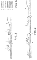
- FIG. 2 to 5 there are represented different steps of the operation of apparatus A,B according to the invention, on rails R being laid down, this apparatus being synchronized with apparatuses S for welding the rails and with apparatuses T for arranging the ballast, in view of the fact that in most cases these different operations are to be effected at the same time.
- the apparatus according to the invention may be inserted in a railway line renewal train, between the apparatuses for laying down the new rails and the apparatuses for welding the same.
- Figure 2 shows that when starting the operation it is of advantage to heat a railway track section K-L already laid down during the foregoing operation, in order to attain a uniform regulation at the passage from the already laid down rails to the rails being laid down at present.
- Figure 3 shows that, when completed the previous heating of the section K-L according to Figure 2, the apparatuses A,B are advanced (towards the right) for heating a new railway track section L-M (which in the meantime has been laid down), whilst the welding machine S advances for welding the joint L and the ballast arranging machine T advances too, behind the welding machine S, for operating onto the railway track section already welded and fixed; the operations effected after the advancement according to Figure 3 are represented in Figure 4. When these operations are completed, a new step of advancement takes place for heating a further section of railway track M-N, which in the meantime has been laid down (Figure 5).
- the application of this invention allows doing an effective thermal regulation of the rails laid down during the installation or the renewal of a railway line, by means of relatively quick and cheap operations, which may be organized with ease at the time of effecting the other required operations.
Landscapes
- Engineering & Computer Science (AREA)
- Architecture (AREA)
- Civil Engineering (AREA)
- Structural Engineering (AREA)
- Mechanical Engineering (AREA)
- Machines For Laying And Maintaining Railways (AREA)
- Railway Tracks (AREA)
- Heat Treatment Of Articles (AREA)
- Escalators And Moving Walkways (AREA)
- General Induction Heating (AREA)
- Electric Propulsion And Braking For Vehicles (AREA)
- Drying Of Solid Materials (AREA)
- Yarns And Mechanical Finishing Of Yarns Or Ropes (AREA)
- Constitution Of High-Frequency Heating (AREA)
Applications Claiming Priority (3)
| Application Number | Priority Date | Filing Date | Title |
|---|---|---|---|
| IT94TO000679A IT1268088B1 (it) | 1994-08-26 | 1994-08-26 | Apparecchiatura per il riscaldamento di rotaie durante la loro posa. |
| ITTO940679 | 1994-08-26 | ||
| PCT/EP1995/003227 WO1996006981A1 (en) | 1994-08-26 | 1995-08-14 | Apparatus for heating rails during the laying down thereof |
Publications (2)
| Publication Number | Publication Date |
|---|---|
| EP0725860A1 EP0725860A1 (en) | 1996-08-14 |
| EP0725860B1 true EP0725860B1 (en) | 2000-01-19 |
Family
ID=11412743
Family Applications (1)
| Application Number | Title | Priority Date | Filing Date |
|---|---|---|---|
| EP95930456A Expired - Lifetime EP0725860B1 (en) | 1994-08-26 | 1995-08-14 | Apparatus for heating rails during the laying down thereof |
Country Status (10)
| Country | Link |
|---|---|
| US (1) | US5804793A (it) |
| EP (1) | EP0725860B1 (it) |
| JP (1) | JP3711286B2 (it) |
| AT (1) | ATE189019T1 (it) |
| AU (1) | AU696042B2 (it) |
| CZ (1) | CZ149396A3 (it) |
| DE (1) | DE69514639T2 (it) |
| FI (1) | FI961773A7 (it) |
| IT (1) | IT1268088B1 (it) |
| WO (1) | WO1996006981A1 (it) |
Families Citing this family (8)
| Publication number | Priority date | Publication date | Assignee | Title |
|---|---|---|---|---|
| EP1223247A1 (en) * | 2001-01-11 | 2002-07-17 | Strukton Railinfra b.v. | Method and apparatus for prestressing rails by electrical heating and method of laying rails |
| US7024923B2 (en) * | 2002-03-22 | 2006-04-11 | Ricoh Company, Ltd. | Method for evaluating fixing member and fixing belt and thermal fixing roller |
| CN101035950B (zh) | 2004-08-20 | 2013-03-06 | 罗兰路线维护股份有限公司 | 长铁轨吊起及运送系统 |
| NL2008641C2 (nl) * | 2012-04-16 | 2013-10-17 | Brouwers Holding B V | Werkwijze voor het verwarmen van een spoorstaafsamenstel. |
| FR3020073B1 (fr) * | 2015-07-27 | 2017-01-13 | Matisa Materiel Ind Sa | Procede de renouvellement de voies ferrees et dispositif pour sa mise en oeuvre |
| IT202100028691A1 (it) | 2021-11-11 | 2023-05-11 | Srt Soc A Responsabilita Limitata Con Socio Unico | Terminale e relativa apparecchiatura per il riscaldamento di rotaie |
| CN114606815B (zh) * | 2022-04-24 | 2024-09-10 | 沈阳铁路信号有限责任公司 | 一种钢轨加热方法及系统 |
| CN115633418B (zh) * | 2022-10-20 | 2026-03-03 | 沈阳铁路信号有限责任公司 | 一种钢轨本体加热装置、方法及热效率验证方法 |
Family Cites Families (12)
| Publication number | Priority date | Publication date | Assignee | Title |
|---|---|---|---|---|
| CH172929A (de) * | 1934-01-06 | 1934-10-31 | Kaegi Emil | Verfahren und Einrichtung zur Verhinderung der Eisbildung und der Ansammlung von Schnee bei Geleiseanlagen, insbesondere Weichen. |
| US3896734A (en) * | 1967-12-29 | 1975-07-29 | Plasser Bahnbaumasch Franz | Apparatus for continuously laying track |
| US3999276A (en) * | 1971-09-16 | 1976-12-28 | Brown Robert M | Method of laying railroad rail |
| US3793544A (en) * | 1972-02-10 | 1974-02-19 | Caterpillar Tractor Co | Multiple winding, multiple voltage, alternator system |
| US4339704A (en) * | 1980-07-07 | 1982-07-13 | General Electric Company | Series parallel transition for power supply |
| US4429845A (en) * | 1982-04-26 | 1984-02-07 | Emerson Electric Co. | Rail track heaters |
| US4656333A (en) * | 1984-12-28 | 1987-04-07 | Murphy John P | Thin profile snow, sleet and moisture sensing detector |
| US5004190A (en) * | 1987-11-06 | 1991-04-02 | Bylin Heating Systems, Inc. | Rail heating apparatus |
| US4815052A (en) * | 1988-07-06 | 1989-03-21 | Honeywell, Inc. | Automatic overvoltage protection circuit |
| DK0466651T3 (da) * | 1990-07-13 | 1996-01-02 | Scheuchzer Sa | Indretning til udskiftning af skinner i et jernbanesporanlæg |
| EP0551798B1 (fr) * | 1992-01-14 | 1996-03-06 | Scheuchzer S.A. | Dispositif de substitution et de neutralisation des rails des voies de chemin de fer |
| US5299504A (en) * | 1992-06-30 | 1994-04-05 | Technical Rail Products, Incorporated | Self-propelled rail heater car with movable induction heating coils |
-
1994
- 1994-08-26 IT IT94TO000679A patent/IT1268088B1/it active IP Right Grant
-
1995
- 1995-08-14 DE DE69514639T patent/DE69514639T2/de not_active Expired - Fee Related
- 1995-08-14 EP EP95930456A patent/EP0725860B1/en not_active Expired - Lifetime
- 1995-08-14 US US08/632,447 patent/US5804793A/en not_active Expired - Fee Related
- 1995-08-14 FI FI961773A patent/FI961773A7/fi not_active Application Discontinuation
- 1995-08-14 CZ CZ961493A patent/CZ149396A3/cs unknown
- 1995-08-14 AT AT95930456T patent/ATE189019T1/de not_active IP Right Cessation
- 1995-08-14 AU AU33836/95A patent/AU696042B2/en not_active Ceased
- 1995-08-14 JP JP50844496A patent/JP3711286B2/ja not_active Expired - Fee Related
- 1995-08-14 WO PCT/EP1995/003227 patent/WO1996006981A1/en not_active Ceased
Also Published As
| Publication number | Publication date |
|---|---|
| AU3383695A (en) | 1996-03-22 |
| JP3711286B2 (ja) | 2005-11-02 |
| CZ149396A3 (en) | 1996-12-11 |
| EP0725860A1 (en) | 1996-08-14 |
| DE69514639D1 (de) | 2000-02-24 |
| US5804793A (en) | 1998-09-08 |
| ITTO940679A1 (it) | 1996-02-26 |
| FI961773A0 (fi) | 1996-04-25 |
| AU696042B2 (en) | 1998-08-27 |
| ITTO940679A0 (it) | 1994-08-26 |
| DE69514639T2 (de) | 2000-08-03 |
| JPH09504586A (ja) | 1997-05-06 |
| IT1268088B1 (it) | 1997-02-20 |
| ATE189019T1 (de) | 2000-02-15 |
| FI961773A7 (fi) | 1996-04-25 |
| WO1996006981A1 (en) | 1996-03-07 |
Similar Documents
| Publication | Publication Date | Title |
|---|---|---|
| EP0725860B1 (en) | Apparatus for heating rails during the laying down thereof | |
| US5896021A (en) | Removal of moisture from induction motors | |
| JP5127312B2 (ja) | 分岐器における融雪・凍結防止装置 | |
| US1412484A (en) | Heat treatment of articles of iron and steel and alloys thereof | |
| US6177656B1 (en) | Method and apparatus for controlling heating and cooling in segments of a fiber glass bushing | |
| US1383963A (en) | Heat treatment of tramway and other rails | |
| AU2015316573B2 (en) | Method, apparatus and vehicle for welding rails | |
| CN206858974U (zh) | 轨枕立螺栓拔出设备 | |
| CN111542144B (zh) | 一种用于中低速磁浮列车供电轨的电磁感应加热除冰装置 | |
| SE9800637D0 (sv) | Method for continuous casting and device for carring out the method | |
| ES2125896T3 (es) | Procedimiento para el mando de una maquina motriz de flujo transversal. | |
| ITTO960230A1 (it) | Apparecchiatura e procedimento per la correzione della regolazione termica di rotaie posate. | |
| RU219969U1 (ru) | Термокамера | |
| WO2004065159A1 (en) | An arrangement and a method for providing electric power to a vehicle | |
| JPH0750408Y2 (ja) | 電気鉄道のレールポイント融雪器用電源装置 | |
| US1778973A (en) | Arc welding system | |
| US370282A (en) | And tempering metals | |
| JPH05132902A (ja) | 鉄道分岐器の融雪装置 | |
| JPS6137860B2 (it) | ||
| SU1082841A1 (ru) | Способ термической обработки рельса | |
| RU142522U1 (ru) | Устройство для индукционного нагрева стрелочного перевода | |
| JP2001115403A (ja) | 線路ポイント部融雪装置 | |
| NL2008641C2 (nl) | Werkwijze voor het verwarmen van een spoorstaafsamenstel. | |
| KR20170029673A (ko) | 용접기 출력을 이용한 열처리 장치 및 방법 | |
| PL235789B1 (pl) | Zestaw do indukcyjnego ogrzewania rozjazdów szynowych |
Legal Events
| Date | Code | Title | Description |
|---|---|---|---|
| PUAI | Public reference made under article 153(3) epc to a published international application that has entered the european phase |
Free format text: ORIGINAL CODE: 0009012 |
|
| AK | Designated contracting states |
Kind code of ref document: A1 Designated state(s): AT BE CH DE DK FR GB IT LI LU NL SE |
|
| 17P | Request for examination filed |
Effective date: 19960829 |
|
| GRAG | Despatch of communication of intention to grant |
Free format text: ORIGINAL CODE: EPIDOS AGRA |
|
| 17Q | First examination report despatched |
Effective date: 19990302 |
|
| GRAG | Despatch of communication of intention to grant |
Free format text: ORIGINAL CODE: EPIDOS AGRA |
|
| GRAH | Despatch of communication of intention to grant a patent |
Free format text: ORIGINAL CODE: EPIDOS IGRA |
|
| GRAH | Despatch of communication of intention to grant a patent |
Free format text: ORIGINAL CODE: EPIDOS IGRA |
|
| GRAA | (expected) grant |
Free format text: ORIGINAL CODE: 0009210 |
|
| AK | Designated contracting states |
Kind code of ref document: B1 Designated state(s): AT BE CH DE DK FR GB IT LI LU NL SE |
|
| PG25 | Lapsed in a contracting state [announced via postgrant information from national office to epo] |
Ref country code: IT Free format text: LAPSE BECAUSE OF FAILURE TO SUBMIT A TRANSLATION OF THE DESCRIPTION OR TO PAY THE FEE WITHIN THE PRE;WARNING: LAPSES OF ITALIAN PATENTS WITH EFFECTIVE DATE BEFORE 2007 MAY HAVE OCCURRED AT ANY TIME BEFORE 2007. THE CORRECT EFFECTIVE DATE MAY BE DIFFERENT FROM THE ONE RECORDED.SCRIBED TIME-LIMIT Effective date: 20000119 |
|
| REF | Corresponds to: |
Ref document number: 189019 Country of ref document: AT Date of ref document: 20000215 Kind code of ref document: T |
|
| REG | Reference to a national code |
Ref country code: CH Ref legal event code: EP |
|
| REF | Corresponds to: |
Ref document number: 69514639 Country of ref document: DE Date of ref document: 20000224 |
|
| REG | Reference to a national code |
Ref country code: CH Ref legal event code: NV Representative=s name: WILLIAM BLANC & CIE CONSEILS EN PROPRIETE INDUSTRI |
|
| ET | Fr: translation filed | ||
| PG25 | Lapsed in a contracting state [announced via postgrant information from national office to epo] |
Ref country code: DK Free format text: LAPSE BECAUSE OF FAILURE TO SUBMIT A TRANSLATION OF THE DESCRIPTION OR TO PAY THE FEE WITHIN THE PRESCRIBED TIME-LIMIT Effective date: 20000419 |
|
| PG25 | Lapsed in a contracting state [announced via postgrant information from national office to epo] |
Ref country code: LU Free format text: LAPSE BECAUSE OF NON-PAYMENT OF DUE FEES Effective date: 20000814 |
|
| PLBE | No opposition filed within time limit |
Free format text: ORIGINAL CODE: 0009261 |
|
| STAA | Information on the status of an ep patent application or granted ep patent |
Free format text: STATUS: NO OPPOSITION FILED WITHIN TIME LIMIT |
|
| 26N | No opposition filed | ||
| REG | Reference to a national code |
Ref country code: GB Ref legal event code: IF02 |
|
| PGFP | Annual fee paid to national office [announced via postgrant information from national office to epo] |
Ref country code: AT Payment date: 20070827 Year of fee payment: 13 |
|
| PGFP | Annual fee paid to national office [announced via postgrant information from national office to epo] |
Ref country code: GB Payment date: 20070712 Year of fee payment: 13 |
|
| PGFP | Annual fee paid to national office [announced via postgrant information from national office to epo] |
Ref country code: SE Payment date: 20070817 Year of fee payment: 13 Ref country code: NL Payment date: 20070831 Year of fee payment: 13 Ref country code: DE Payment date: 20070927 Year of fee payment: 13 Ref country code: BE Payment date: 20070726 Year of fee payment: 13 |
|
| PGFP | Annual fee paid to national office [announced via postgrant information from national office to epo] |
Ref country code: FR Payment date: 20070731 Year of fee payment: 13 |
|
| EUG | Se: european patent has lapsed | ||
| GBPC | Gb: european patent ceased through non-payment of renewal fee |
Effective date: 20080814 |
|
| PG25 | Lapsed in a contracting state [announced via postgrant information from national office to epo] |
Ref country code: AT Free format text: LAPSE BECAUSE OF NON-PAYMENT OF DUE FEES Effective date: 20080814 |
|
| NLV4 | Nl: lapsed or anulled due to non-payment of the annual fee |
Effective date: 20090301 |
|
| PG25 | Lapsed in a contracting state [announced via postgrant information from national office to epo] |
Ref country code: NL Free format text: LAPSE BECAUSE OF NON-PAYMENT OF DUE FEES Effective date: 20090301 |
|
| REG | Reference to a national code |
Ref country code: FR Ref legal event code: ST Effective date: 20090430 |
|
| PG25 | Lapsed in a contracting state [announced via postgrant information from national office to epo] |
Ref country code: BE Free format text: LAPSE BECAUSE OF NON-PAYMENT OF DUE FEES Effective date: 20080831 |
|
| PG25 | Lapsed in a contracting state [announced via postgrant information from national office to epo] |
Ref country code: FR Free format text: LAPSE BECAUSE OF NON-PAYMENT OF DUE FEES Effective date: 20080901 Ref country code: DE Free format text: LAPSE BECAUSE OF NON-PAYMENT OF DUE FEES Effective date: 20090303 |
|
| PG25 | Lapsed in a contracting state [announced via postgrant information from national office to epo] |
Ref country code: GB Free format text: LAPSE BECAUSE OF NON-PAYMENT OF DUE FEES Effective date: 20080814 |
|
| REG | Reference to a national code |
Ref country code: CH Ref legal event code: PFA Owner name: FAROLDI, BRUNO Free format text: FAROLDI, BRUNO#VIA BERENINI, 119#43036 FIDENZA (IT) -TRANSFER TO- FAROLDI, BRUNO#VIA BERENINI, 119#43036 FIDENZA (IT) |
|
| PG25 | Lapsed in a contracting state [announced via postgrant information from national office to epo] |
Ref country code: SE Free format text: LAPSE BECAUSE OF NON-PAYMENT OF DUE FEES Effective date: 20080815 |
|
| REG | Reference to a national code |
Ref country code: CH Ref legal event code: PCAR Free format text: NOVAGRAAF SWITZERLAND SA;CHEMIN DE L'ECHO 3;1213 ONEX (CH) |
|
| PGFP | Annual fee paid to national office [announced via postgrant information from national office to epo] |
Ref country code: CH Payment date: 20140821 Year of fee payment: 20 |
|
| REG | Reference to a national code |
Ref country code: CH Ref legal event code: PL |