EP0724971A1 - Leichtmetallrad - Google Patents
Leichtmetallrad Download PDFInfo
- Publication number
- EP0724971A1 EP0724971A1 EP96400218A EP96400218A EP0724971A1 EP 0724971 A1 EP0724971 A1 EP 0724971A1 EP 96400218 A EP96400218 A EP 96400218A EP 96400218 A EP96400218 A EP 96400218A EP 0724971 A1 EP0724971 A1 EP 0724971A1
- Authority
- EP
- European Patent Office
- Prior art keywords
- wheel
- web
- rim
- wheel according
- lights
- Prior art date
- Legal status (The legal status is an assumption and is not a legal conclusion. Google has not performed a legal analysis and makes no representation as to the accuracy of the status listed.)
- Granted
Links
Images


Classifications
-
- B—PERFORMING OPERATIONS; TRANSPORTING
- B60—VEHICLES IN GENERAL
- B60B—VEHICLE WHEELS; CASTORS; AXLES FOR WHEELS OR CASTORS; INCREASING WHEEL ADHESION
- B60B3/00—Disc wheels, i.e. wheels with load-supporting disc body
- B60B3/06—Disc wheels, i.e. wheels with load-supporting disc body formed by casting
Definitions
- the present invention relates generally to light alloy wheels for automobiles.
- automobiles is meant here and throughout the rest of the text light or semi-light vehicles as opposed to heavy goods vehicles.
- the present invention is based on an approach completely opposite to the above approach.
- the present invention relates to a molded wheel of aluminum alloy for motor vehicles, of the type comprising a veil and a rim, characterized in that the veil has a generally smooth zone, in which light gain and ventilation lights are formed. brake, and adjacent areas, generally full and smooth, in that all of the geometrical characteristics of the wheel are determined solely on the basis of considerations of mechanical strength of the wheel, and in that it comprises in the region of transition between the web and the rim of the attachment means of a hubcap having only an aesthetic function.
- the veil of such a wheel is devoid of any relief and has no area with angular geometry.
- the wheel comprises a web 10 in which are formed, on the one hand, in a central mounting area 10a, a set of passages 11 for wheel mounting bolts, and, on the other hand, a set of lights 12 weight gain and brake ventilation.
- the wheel also includes a rim 20 ending on the inside (on the left in FIG. 3) with a return 21 for retaining the tire and on the outside with a part 22 known as a "hook” comprising a section 221 forming a hook as well as beyond section 221, a tire retaining section 222.
- Section 221 is used to retain a hubcap at 223, as well as internal support for the tire.
- Weight gain is sought by retaining at the wheel all the admissible qualities in terms of resistance to both fatigue and impact.
- the lights of weight gain 12 could be practiced in an area of the wall of which the diameter ⁇ ext is between 70% of the standard diameter ⁇ N of the wheel (defined by the surface of section 221 forming internal support for the tire) and 90% of this diameter ⁇ N.
- the diameter ⁇ int is defined by the inner tangent circle of the lights made in the veil.
- lights are made only in a ring with an outside diameter ⁇ ext and an inside diameter ⁇ int .
- This zone is designated by the reference Z2 in FIG. 1, while the zones situated inside and outside, generally smooth, are designated respectively by Z1 and Z3.
- the lights 12 made in the zone Z2 have rounded edges on the outside of the wheel and preferably circular. However, they may show some ovalization.
- the minimum distance between two adjacent openings 12 should be chosen with care, here again in order to maintain a satisfactory resistance to fatigue rupture.
- r c a radius of curvature preferably between 1 and 6 mm.
- the curvature of the veil is such that the centers of curvature are at all points located on the inside of the veil.
- the outer face of the web is generally convex, and there is in its profile, between the central mounting area 10A and its connection with the rim 20 at point A no point of inflection.
- the Applicant has also observed that the manner in which the web, the rim and the hook of the wheel are connected has a significant influence, in particular on the impact resistance.
- FIG. 3 shows that the hook part 22 and the outermost region of the veil define, together with a relief 223 provided on the part 221, a groove G which makes it possible to lighten the wheel and the attachment of a hub cap intended for cover the entire veil, using elastic tabs or the like secured to said hubcap.
- this hub cap then only has an aesthetic function and does not intervene in any way in the mechanical maintenance of the wheel.
- the wheel can be slightly stylized, in which case it is not necessary to provide a hubcap.
- the sections 221 and 222 of the hook part have a reduced thickness, in favor of the lightness of the wheel.
- the thickness, denoted e c , of the hook portion 22 near its connection to the web and to the rim (connection point A) is advantageously chosen to be greater than the thickness of the web, denoted e v , in the vicinity of said connection.
- these thicknesses satisfy the relationship: e vs / e v ⁇ 1.35
- the rim thickness is between 2.5 and 4 mm.
- the aforementioned point A which is located at the intersection of the neutral fibers of the web, of the rim and of the hook part, is located at a horizontal distance (denoted DA) from the median plane PM of the wheel which is not too large with respect to the half-width, denoted L, of the rim 20.
- ⁇ S the diameter of the circle on which are the points S corresponding to the different radial sections of the wheel
- this diameter satisfies the following relationship: 0.5. ⁇ NOT ⁇ ⁇ S ⁇ 0.75. ⁇ NOT
- the invention finds its interest in light alloy wheels, typically a conventional aluminum alloy of the AS7G0.3 type. Conventional heat treatments and hardening will be practiced on the wheel to increase the mechanical resistance and the fatigue life of the wheel, in particular.
- a diametrically opposite lumen may be partially or completely blocked.
- the wheels are in these examples all molded at low pressure, in a metal mold mainly consisting of a sole pierced in its center with a filling system, an upper core defining the interior relief of the wheel, and two yokes lateral defining the outer surface of the veil.
- the upper core and the sole are provided with cooling channels allowing, according to the state of the art, the progressive control of solidification from the ends 21 and 222 of the web as far as the central filling zone (linked to 10 A).
- the molding rate is between 10 and 12 wheels per hour.
- the temperature of the liquid metal in the oven is 698 ° C ⁇ 5 ° C.
- the metal used is AS7G0.3, consisting essentially of primary aluminum, 7% silicon ⁇ 0.5% and 0.30% magnesium ⁇ 0.1%.
- the final geometry of the wheel is obtained by a juxtaposition of rough molding zones and machined zones as usual for aluminum rims.
- the wheels undergo a fatigue test on a bidirectional test bench, the stress principle of which is given in FIG. 4.
- the wheel designated by R in this FIG. 4, is mounted on a plate P rotating around an axis A.
- the wheel R is fixed on this plate P by several flanges S cooperating with the inner edge of the rim.
- a lever arm system ensures the transmission to the wheel of forces F y and F z in horizontal and vertical directions by its central part bolted to an arm B.
- the fatigue resistance of the wheel is assessed after a certain number of cycles under stresses F y and F z , by penetrant testing and visual examination, so as to detect the presence or not of fatigue cracks.
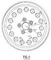
- the first example is a wheel produced according to the invention and the front view and the characteristic section of which are shown in FIGS. 5 and 6.
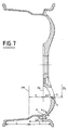
- the second example is a wheel produced outside the invention and the front view and the characteristic section of which are given in FIGS. 7 and 8 respectively. In the same way as FIGS. 5 and 6, these two figures are also integrated into the present description.
- This wheel is distinguished from the invention by the presence of the lights too close to its center.
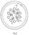
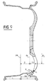
- the third example is a wheel produced outside the invention and the front view and the characteristic section of which are given in FIGS. 9 and 10 respectively, similar to FIGS. 5 and 6 and also integrated into the present description.
- This wheel is distinguished from the invention by openings whose eccentricity is not consistent.
- the weight of the wheel is 5.6 kg.
Landscapes
- Engineering & Computer Science (AREA)
- Mechanical Engineering (AREA)
- Molds, Cores, And Manufacturing Methods Thereof (AREA)
- Braking Arrangements (AREA)
Applications Claiming Priority (2)
| Application Number | Priority Date | Filing Date | Title |
|---|---|---|---|
| FR9501103A FR2729893B1 (fr) | 1995-01-31 | 1995-01-31 | Roue en alliage leger |
| FR9501103 | 1995-01-31 |
Publications (2)
| Publication Number | Publication Date |
|---|---|
| EP0724971A1 true EP0724971A1 (de) | 1996-08-07 |
| EP0724971B1 EP0724971B1 (de) | 2001-08-08 |
Family
ID=9475683
Family Applications (1)
| Application Number | Title | Priority Date | Filing Date |
|---|---|---|---|
| EP19960400218 Expired - Lifetime EP0724971B1 (de) | 1995-01-31 | 1996-01-31 | Leichtmetallrad |
Country Status (4)
| Country | Link |
|---|---|
| EP (1) | EP0724971B1 (de) |
| DE (1) | DE69614281T2 (de) |
| ES (1) | ES2161335T3 (de) |
| FR (1) | FR2729893B1 (de) |
Citations (9)
| Publication number | Priority date | Publication date | Assignee | Title |
|---|---|---|---|---|
| FR2290316A1 (fr) * | 1974-11-09 | 1976-06-04 | Gkn Kent Alloys Ltd | Roue moulee pour vehicules |
| US4316637A (en) * | 1978-08-04 | 1982-02-23 | Reynolds Metals Company | Multi-styled aluminum wheel |
| EP0074118A2 (de) * | 1981-09-08 | 1983-03-16 | Stahlschmidt & Maiworm GmbH & Co.KG | Leichtmetallfelge für Nutzfahrzeuge |
| EP0301472A1 (de) * | 1987-07-28 | 1989-02-01 | Bayerische Motoren Werke Aktiengesellschaft, Patentabteilung AJ-3 | Herstell-Verfahren für Leichtmetallguss-Bauteile, insbesondere Leichtmetallgussräder für Personenkraftwagen |
| US4861113A (en) * | 1987-02-25 | 1989-08-29 | Topy Kogyo Kabushiki Kaisha | Cast wheel |
| GB2249063A (en) * | 1990-09-13 | 1992-04-29 | Topy Ind | Light alloy cast wheel |
| EP0546307A1 (de) * | 1991-12-12 | 1993-06-16 | Dr.Ing.h.c. F. Porsche Aktiengesellschaft | Leichtmetallrad für ein Kraftfahrzeug |
| EP0549141A2 (de) * | 1991-11-29 | 1993-06-30 | Alloy Wheels International Ltd | Gussform zum Giessen eines Fahrzeugrads und Verfahren zu deren Herstellung |
| DE4321057A1 (de) * | 1992-06-25 | 1994-01-13 | Lacks Ind Inc | Metallplattiertes zusammengesetztes Rad |
-
1995
- 1995-01-31 FR FR9501103A patent/FR2729893B1/fr not_active Expired - Fee Related
-
1996
- 1996-01-31 ES ES96400218T patent/ES2161335T3/es not_active Expired - Lifetime
- 1996-01-31 DE DE1996614281 patent/DE69614281T2/de not_active Expired - Fee Related
- 1996-01-31 EP EP19960400218 patent/EP0724971B1/de not_active Expired - Lifetime
Patent Citations (9)
| Publication number | Priority date | Publication date | Assignee | Title |
|---|---|---|---|---|
| FR2290316A1 (fr) * | 1974-11-09 | 1976-06-04 | Gkn Kent Alloys Ltd | Roue moulee pour vehicules |
| US4316637A (en) * | 1978-08-04 | 1982-02-23 | Reynolds Metals Company | Multi-styled aluminum wheel |
| EP0074118A2 (de) * | 1981-09-08 | 1983-03-16 | Stahlschmidt & Maiworm GmbH & Co.KG | Leichtmetallfelge für Nutzfahrzeuge |
| US4861113A (en) * | 1987-02-25 | 1989-08-29 | Topy Kogyo Kabushiki Kaisha | Cast wheel |
| EP0301472A1 (de) * | 1987-07-28 | 1989-02-01 | Bayerische Motoren Werke Aktiengesellschaft, Patentabteilung AJ-3 | Herstell-Verfahren für Leichtmetallguss-Bauteile, insbesondere Leichtmetallgussräder für Personenkraftwagen |
| GB2249063A (en) * | 1990-09-13 | 1992-04-29 | Topy Ind | Light alloy cast wheel |
| EP0549141A2 (de) * | 1991-11-29 | 1993-06-30 | Alloy Wheels International Ltd | Gussform zum Giessen eines Fahrzeugrads und Verfahren zu deren Herstellung |
| EP0546307A1 (de) * | 1991-12-12 | 1993-06-16 | Dr.Ing.h.c. F. Porsche Aktiengesellschaft | Leichtmetallrad für ein Kraftfahrzeug |
| DE4321057A1 (de) * | 1992-06-25 | 1994-01-13 | Lacks Ind Inc | Metallplattiertes zusammengesetztes Rad |
Also Published As
| Publication number | Publication date |
|---|---|
| FR2729893A1 (fr) | 1996-08-02 |
| ES2161335T3 (es) | 2001-12-01 |
| DE69614281D1 (de) | 2001-09-13 |
| FR2729893B1 (fr) | 1997-04-18 |
| DE69614281T2 (de) | 2002-05-08 |
| EP0724971B1 (de) | 2001-08-08 |
Similar Documents
| Publication | Publication Date | Title |
|---|---|---|
| EP0715001B1 (de) | Verfahren zur Herstellung einer Fahrradfelge und nach diesem Verfahren hergestellte Felge | |
| FR2767285A1 (fr) | Rayon pour roue de cycle, roue de cycle et procedes de fabrication | |
| FR2730778A1 (fr) | Disque de frein en aluminium | |
| EP3645304B1 (de) | Rollensatz mit einer felge, deren flansch eine stütze mit vergrösserter axialer breite bildet | |
| EP0912352B1 (de) | Rad mit schalldämpfung | |
| CA3067565A1 (fr) | Jante a crochet de forme optimisee | |
| JP4543218B2 (ja) | 軽合金ホイールリムの製造方法及びそれにより作られたホイールリム | |
| FR3028802A1 (fr) | Jante pour roue de cycle et son procede de fabrication | |
| FR2904789A1 (fr) | Roue en alliage leger a branches pour automobile | |
| EP0724971B1 (de) | Leichtmetallrad | |
| US4589177A (en) | Method of manufacturing, without welding, light alloy rims for motor vehicles | |
| WO2018020152A1 (fr) | Extenseur et jante pour ensemble roulant, ensemble forme par l'extenseur et la jante, et ensemble roulant les comprenant | |
| CA1051645A (fr) | Procede de fabrication de roues monoblocs par matricage | |
| EP3807103B1 (de) | Fahrzeugradfelge | |
| EP1187730B1 (de) | Rad mit schalldämpfung | |
| EP2254760B1 (de) | Aufhängungssystem für ein fahrzeug und reifen für ein fahrzeug | |
| WO2004103731A1 (fr) | Procede de fabrication d'une roue monobloc en alliage leger pour vehicule automobile | |
| CN109501514A (zh) | 自动两轮车的车轮 | |
| FR3142705A1 (fr) | Jante pour roue assemblée pour loger un moteur électrique de véhicule. | |
| FR2826609A1 (fr) | Procede de fabrication d'une jante en alliage leger, et jante en alliage leger amelioree, pour vehicule automobile | |
| JP2004359045A (ja) | ホイール | |
| JPH05310001A (ja) | 車両用ホイール及びその製造方法 | |
| EP4301610A1 (de) | Seitenwandeinsatz für motorradreifen | |
| JPH0732805A (ja) | 自動車用ホィール | |
| JP2006240406A (ja) | 車両用ホイール |
Legal Events
| Date | Code | Title | Description |
|---|---|---|---|
| PUAI | Public reference made under article 153(3) epc to a published international application that has entered the european phase |
Free format text: ORIGINAL CODE: 0009012 |
|
| AK | Designated contracting states |
Kind code of ref document: A1 Designated state(s): DE ES FR GB IT SE |
|
| 17P | Request for examination filed |
Effective date: 19970205 |
|
| 17Q | First examination report despatched |
Effective date: 19980529 |
|
| GRAG | Despatch of communication of intention to grant |
Free format text: ORIGINAL CODE: EPIDOS AGRA |
|
| GRAG | Despatch of communication of intention to grant |
Free format text: ORIGINAL CODE: EPIDOS AGRA |
|
| GRAH | Despatch of communication of intention to grant a patent |
Free format text: ORIGINAL CODE: EPIDOS IGRA |
|
| GRAH | Despatch of communication of intention to grant a patent |
Free format text: ORIGINAL CODE: EPIDOS IGRA |
|
| GRAA | (expected) grant |
Free format text: ORIGINAL CODE: 0009210 |
|
| AK | Designated contracting states |
Kind code of ref document: B1 Designated state(s): DE ES FR GB IT SE |
|
| REF | Corresponds to: |
Ref document number: 69614281 Country of ref document: DE Date of ref document: 20010913 |
|
| GBT | Gb: translation of ep patent filed (gb section 77(6)(a)/1977) |
Effective date: 20011102 |
|
| REG | Reference to a national code |
Ref country code: ES Ref legal event code: FG2A Ref document number: 2161335 Country of ref document: ES Kind code of ref document: T3 |
|
| PGFP | Annual fee paid to national office [announced via postgrant information from national office to epo] |
Ref country code: ES Payment date: 20011220 Year of fee payment: 7 |
|
| REG | Reference to a national code |
Ref country code: GB Ref legal event code: IF02 |
|
| PGFP | Annual fee paid to national office [announced via postgrant information from national office to epo] |
Ref country code: SE Payment date: 20020117 Year of fee payment: 7 |
|
| PLBE | No opposition filed within time limit |
Free format text: ORIGINAL CODE: 0009261 |
|
| STAA | Information on the status of an ep patent application or granted ep patent |
Free format text: STATUS: NO OPPOSITION FILED WITHIN TIME LIMIT |
|
| 26N | No opposition filed | ||
| PG25 | Lapsed in a contracting state [announced via postgrant information from national office to epo] |
Ref country code: SE Free format text: LAPSE BECAUSE OF NON-PAYMENT OF DUE FEES Effective date: 20030201 Ref country code: ES Free format text: LAPSE BECAUSE OF NON-PAYMENT OF DUE FEES Effective date: 20030201 |
|
| EUG | Se: european patent has lapsed | ||
| REG | Reference to a national code |
Ref country code: ES Ref legal event code: FD2A Effective date: 20030201 |
|
| PGFP | Annual fee paid to national office [announced via postgrant information from national office to epo] |
Ref country code: DE Payment date: 20050107 Year of fee payment: 10 |
|
| PGFP | Annual fee paid to national office [announced via postgrant information from national office to epo] |
Ref country code: FR Payment date: 20050117 Year of fee payment: 10 |
|
| PGFP | Annual fee paid to national office [announced via postgrant information from national office to epo] |
Ref country code: GB Payment date: 20050126 Year of fee payment: 10 |
|
| PG25 | Lapsed in a contracting state [announced via postgrant information from national office to epo] |
Ref country code: GB Free format text: LAPSE BECAUSE OF NON-PAYMENT OF DUE FEES Effective date: 20060131 Ref country code: FR Free format text: LAPSE BECAUSE OF NON-PAYMENT OF DUE FEES Effective date: 20060131 |
|
| PGFP | Annual fee paid to national office [announced via postgrant information from national office to epo] |
Ref country code: IT Payment date: 20060131 Year of fee payment: 11 |
|
| PG25 | Lapsed in a contracting state [announced via postgrant information from national office to epo] |
Ref country code: DE Free format text: LAPSE BECAUSE OF NON-PAYMENT OF DUE FEES Effective date: 20060801 |
|
| GBPC | Gb: european patent ceased through non-payment of renewal fee |
Effective date: 20060131 |
|
| REG | Reference to a national code |
Ref country code: FR Ref legal event code: ST Effective date: 20060929 |
|
| PG25 | Lapsed in a contracting state [announced via postgrant information from national office to epo] |
Ref country code: IT Free format text: LAPSE BECAUSE OF NON-PAYMENT OF DUE FEES Effective date: 20070131 |