EP0724931A1 - Off-line Honen von Aufschnitt-Schneidemaschine-Messern - Google Patents
Off-line Honen von Aufschnitt-Schneidemaschine-Messern Download PDFInfo
- Publication number
- EP0724931A1 EP0724931A1 EP96300121A EP96300121A EP0724931A1 EP 0724931 A1 EP0724931 A1 EP 0724931A1 EP 96300121 A EP96300121 A EP 96300121A EP 96300121 A EP96300121 A EP 96300121A EP 0724931 A1 EP0724931 A1 EP 0724931A1
- Authority
- EP
- European Patent Office
- Prior art keywords
- honing
- assembly
- blade
- cutting surface
- slicer
- Prior art date
- Legal status (The legal status is an assumption and is not a legal conclusion. Google has not performed a legal analysis and makes no representation as to the accuracy of the status listed.)
- Withdrawn
Links
- 238000005520 cutting process Methods 0.000 claims abstract description 43
- 230000002093 peripheral effect Effects 0.000 claims abstract description 20
- 238000000034 method Methods 0.000 claims abstract description 15
- 230000020347 spindle assembly Effects 0.000 claims description 50
- 239000012530 fluid Substances 0.000 claims description 8
- 235000013305 food Nutrition 0.000 claims description 8
- 230000037361 pathway Effects 0.000 claims description 7
- 230000001154 acute effect Effects 0.000 claims 2
- 238000013459 approach Methods 0.000 description 7
- 235000013372 meat Nutrition 0.000 description 5
- 238000012545 processing Methods 0.000 description 5
- 230000000712 assembly Effects 0.000 description 4
- 238000000429 assembly Methods 0.000 description 4
- 125000006850 spacer group Chemical group 0.000 description 4
- 230000008901 benefit Effects 0.000 description 3
- 230000015572 biosynthetic process Effects 0.000 description 3
- 230000000694 effects Effects 0.000 description 3
- 239000002245 particle Substances 0.000 description 3
- 230000009471 action Effects 0.000 description 2
- 235000013351 cheese Nutrition 0.000 description 2
- 230000003993 interaction Effects 0.000 description 2
- 239000010687 lubricating oil Substances 0.000 description 2
- 230000007246 mechanism Effects 0.000 description 2
- 238000011012 sanitization Methods 0.000 description 2
- 241000269319 Squalius cephalus Species 0.000 description 1
- 230000003213 activating effect Effects 0.000 description 1
- 235000015241 bacon Nutrition 0.000 description 1
- 238000004140 cleaning Methods 0.000 description 1
- 239000010730 cutting oil Substances 0.000 description 1
- 239000000428 dust Substances 0.000 description 1
- 230000006870 function Effects 0.000 description 1
- 239000007788 liquid Substances 0.000 description 1
- 230000001050 lubricating effect Effects 0.000 description 1
- 238000004519 manufacturing process Methods 0.000 description 1
- 238000012986 modification Methods 0.000 description 1
- 230000004048 modification Effects 0.000 description 1
- 238000012544 monitoring process Methods 0.000 description 1
- 239000003921 oil Substances 0.000 description 1
- 230000001681 protective effect Effects 0.000 description 1
- 230000000284 resting effect Effects 0.000 description 1
- 238000004513 sizing Methods 0.000 description 1
- 238000005303 weighing Methods 0.000 description 1
Images


Classifications
-
- B—PERFORMING OPERATIONS; TRANSPORTING
- B24—GRINDING; POLISHING
- B24B—MACHINES, DEVICES, OR PROCESSES FOR GRINDING OR POLISHING; DRESSING OR CONDITIONING OF ABRADING SURFACES; FEEDING OF GRINDING, POLISHING, OR LAPPING AGENTS
- B24B17/00—Special adaptations of machines or devices for grinding controlled by patterns, drawings, magnetic tapes or the like; Accessories therefor
- B24B17/02—Special adaptations of machines or devices for grinding controlled by patterns, drawings, magnetic tapes or the like; Accessories therefor involving mechanical transmission means only
- B24B17/025—Special adaptations of machines or devices for grinding controlled by patterns, drawings, magnetic tapes or the like; Accessories therefor involving mechanical transmission means only for grinding rotating workpieces (three dimensional)
- B24B17/026—Special adaptations of machines or devices for grinding controlled by patterns, drawings, magnetic tapes or the like; Accessories therefor involving mechanical transmission means only for grinding rotating workpieces (three dimensional) for the periphery of plane workpieces, e.g. cams, lenses
-
- B—PERFORMING OPERATIONS; TRANSPORTING
- B24—GRINDING; POLISHING
- B24B—MACHINES, DEVICES, OR PROCESSES FOR GRINDING OR POLISHING; DRESSING OR CONDITIONING OF ABRADING SURFACES; FEEDING OF GRINDING, POLISHING, OR LAPPING AGENTS
- B24B27/00—Other grinding machines or devices
- B24B27/0076—Other grinding machines or devices grinding machines comprising two or more grinding tools
-
- B—PERFORMING OPERATIONS; TRANSPORTING
- B24—GRINDING; POLISHING
- B24B—MACHINES, DEVICES, OR PROCESSES FOR GRINDING OR POLISHING; DRESSING OR CONDITIONING OF ABRADING SURFACES; FEEDING OF GRINDING, POLISHING, OR LAPPING AGENTS
- B24B3/00—Sharpening cutting edges, e.g. of tools; Accessories therefor, e.g. for holding the tools
- B24B3/36—Sharpening cutting edges, e.g. of tools; Accessories therefor, e.g. for holding the tools of cutting blades
- B24B3/46—Sharpening cutting edges, e.g. of tools; Accessories therefor, e.g. for holding the tools of cutting blades of disc blades
- B24B3/463—Sharpening cutting edges, e.g. of tools; Accessories therefor, e.g. for holding the tools of cutting blades of disc blades of slicing machine disc blades
Definitions
- the present invention generally relates to honing of cutting devices by which components such as slicer blades are sharpened, honed or ground along their respective cutting edges.
- the invention is particularly well-suited for honing, grinding and/or sharpening blades for slicing food products such as large sticks, chubs, loaves or pieces of meat, luncheon meat, cheese and the like.
- These slicing blades typically have a curved cutting surface or edge portion along all or a substantial part of the periphery of the slicer blade.
- the invention includes use of a cam member that has a curved pathway at least a portion of which emulates the profile or peripheral shape of the slicing edge of the blade.
- One or more honing spindle assemblies are associated with cam followers which engage and follow the camming surface of the cam member. Rotating honing wheels off these honing spindle assemblies closely follow the peripheral edge portion of the blade to effect the honing action in a uniform and accurate manner.
- the invention also allows substantially simultaneous honing of generally oppositely facing ground surfaces to minimize the presence of burring on the finished, fully honed blade.
- Slicing equipment for foods and the like are in use within the food processing industry and in other situations when elongated products need to be severed into thin slices. This is especially the case for food processing plants wherein finished products such as sliced luncheon meats, sliced bacon, sliced meat cuts, sliced cheese and the like are processed through a large industrial-scale slicer. In a typical operation, these slices are then packaged and distributed for retail sale as convenient ready-to-sell units.
- Commercial slicer equipment that is used for slicing and sometimes also stacking and weighing the slices are or have been available from well-known manufacturers such as Cashin, Anco, Formax, Great Lakes and Thurne. Each manufacturer generally uses a blade or blades of differing shape and/or sizing.
- the blades can have peripheral shapes which are circular, involute, spiral, and the like, each of which has a curved surface of constant radius or varying radii along the periphery of the cutting surface. Each blade is somewhat large and has substantial area that is at least nominally flat.
- this slicer equipment provide honing devices attached to the slicer itself. This approach is taken in order to afford an apparent advantage of achieving honing through an on-line approach which avoids the need to remove the large blade from the slicer in order to hone or sharpen it.
- this on-line approach has disadvantages which often outweigh this advantage.
- honing or sharpening on-line the resultant grinding dust or particles will often be deposited at locations which could find their way into the food product. Accordingly, it is essential to totally sanitize entire areas of the slicing equipment in addition to cleaning of the blade itself.
- the slicer and in many cases a production line of which it is but one component, must be shut down during the entire course of the sharpening and clean-up operations.
- the present invention avoids these disadvantages by providing a honing apparatus that is totally removed from the large slicing equipment.
- the slicing equipment and food processing line of which it may be a component need to be shut down for only the time that is required to remove the dull blade and replace it with another, previously sharpened or honed or ground blade.
- this fresh blade needs to be treated for sanitary reasons, such as by simply squirting appropriate aqueous liquid onto the blade which had been thoroughly cleaned and sanitized and at a location remote from the food processing area to remove grinding particles and the like prior to mounting it onto the slicer equipment.
- This approach minimizes downtime and does not have the handling constraints which are characteristic of on-line devices.
- Another difficulty which is often encountered in sharpening large blades such as the large slicer blades for commercial meat slicers is the difficulty in maintaining flatness of blades having such an extensive peripheral edge.
- Another challenge for off-line honers is having them arranged so as to be suitable for use with any one of the variety of differently sized and/or shaped blades that are required for the various slicers in commercial use. Each such blade has a curved periphery, but curve size and shape varies from blade to blade. This difficulty is particularly evident when a processing plant utilizes slicers of different manufacturers and/or of different sizes.
- the apparatus of the invention includes a cam member having a curved pathway or camming surface that is shaped to follow a curved cutting surface of a particular type of cutting blade.
- cam members can be provided, each one of which being sized and shaped for a particular style and size of slicer blade.
- Various such blades and cam members are interchangeably mounted on a rotation assembly that rotates a properly sized and shaped cam member and its corresponding cutter blade together.
- a cam follower of a honing spindle assembly engages the cam member in order to thereby assist in directing a rotating honing wheel or the like along the blade surface to be honed, sharpened or ground.
- a suitable biasing assembly ensures contact is maintained between the cam follower and the cam member. In this way, the rotating honing wheel or the like closely follows the curvature of the particular blade being sharpened.
- at least two honing spindle assemblies are provided, and a top peripheral edge as a well as bottom peripheral edge of the slicer blade are honed substantially simultaneously in order to provide a finished honed blade that is deburred.
- Another object of this invention is to provide an improved off-line honing apparatus and method which reduces down-time and minimizes sanitization procedures associated with maintaining a sharp and properly honed blade on commercial slicers.
- Another object of the present invention is to provide an improved off-line honing apparatus and method which avoids the need for total sanitation procedures associated with slicer blade sharpening.
- Another object of this invention is to provide an improved honing apparatus and method which reduces down time for blade sharpening to the time required to exchange slicer blades on the slicing apparatus.
- Another object of the present invention is to provide improved honing of slicer blades that minimizes the formation of burrs.
- Another object of this invention is to provide an improved apparatus and method for attaining superior sharpness levels on large slicer blades.
- Another object of the present invention is to provide an improved honing apparatus and method which maintains close tolerances with respect to blade flatness and particularly cutting edge flatness, while forming honed or ground cutting edge surfaces which are of substantially uniform width throughout their respective peripheral lengths.
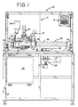
- An off-line honer generally designated at 21 in Fig. 1, is illustrated within a shroud or closeable cabinet, generally designated at 22, resting on a suitable support structure, generally designated at 23.
- This overall arrangement is illustrative of other possible structures for supporting and enclosing the off-line honer assembly.
- the use of an enclosure cabinet 22 is useful in avoiding undesirable dissipation of honing debris, including ground particles and lubricating oil which will be prevented from leaving the cabinet during honing procedures, as desired.
- a turntable assembly is provided for supporting and rotating the blade to be honed, ground or sharpened. It is driven by a motor assembly, generally designated at 25.
- a carriage assembly generally designated at 26 movably supports one or more spindle assemblies, two spindle assemblies 27 and 28 being illustrated.
- the honing component of each spindle assembly closely follows the curvature of the blade being honed, ground or sharpened while it is rotated by operation of the motor assembly.
- Suitable control equipment preferably including computer hardware and software programmed to provide desired control outputs for each given style or size of cutter blade, are suitably housed in control cabinet 29.
- a control panel 31 allows the operator to input certain data and functions in order, for example, to select the proper program for the blade to be honed, ground or sharpened.
- elongated guide pins 32, 33 are mounted to the support structure 23 by suitable supports 34, 35, 36, 37.
- Slide plates 38, 39 are slidably mounted onto both of the elongated guide pins 32, 33. In the illustrated embodiment, this slidability is facilitated by bearing assemblies 41, 42.
- Protective accordion covers or boots 43, 44 are preferably included to provide protection from honing debris for the elongated guide pins 32, 33.
- Rigid cylinders 45, 46 provide protection for the remainder of the elongated guide pins and structurally join the slide plates 38, 39 such as through the bearing assemblies 41, 42.
- the slide plates 38, 39, bearing assemblies 41, 42 and rigid cylindrical covers 45, 46 constitute components of a sliding support assembly for the spindle assemblies 27, 28, by virtue of which the spindle assemblies will move, as required by the camming arrangement and/or program for the particular blade being honed, ground or sharpened.
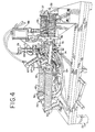
- the illustrated sliding support assembly includes a support bar 47 (Fig. 3) secured between the slide plates 38, 39 and to which the spindle assemblies 27, 28 are mounted.
- a two-way fluid cylinder 48 affects movement of the sliding support assembly.
- its rod 49 is secured to the slide plate 39.
- one or more of the spindle assemblies can include a subsidiary adjustment mechanism.
- one of the spindle assemblies 28 includes an independent mounting arrangement to allow this spindle assembly to slide without causing sliding of the other spindle assembly 27. Included in this regard is a slidable mount 51 for the spindle assembly 28.
- the rod 52 of another two-way fluid cylinder 53 is provided in order to allow and/or effect sliding movement of the spindle assembly 28.
- two-way fluid cylinder 48 is substantially larger in stroke than is the two-way fluid cylinder 53.
- cylinder 48 can have a fourteen inch (35.56cm) stroke, while cylinder 53 can have a six inch (15.24 cm) stroke.
- the illustrated embodiment includes two such assemblies.
- Assembly 27 is shown in the drawings for honing or grinding the primary angle bottom width of the cutting edge of the blade, while the assembly 28 is shown for honing or grinding the top land width of the blade.
- spindle assembly 27 is shown honing or grinding a primary angle on the so-called bottom surface of the peripheral cutting edge of a blade 54
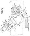
- spindle assembly 28 is shown honing or grinding a so-called top flat land width of the peripheral cutting edge of the blade 54. This is perhaps best shown in Figs. 4, 5, 13 and 14.
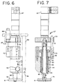
- FIGs. 4, 5, 6 and 7. A mounting plate 55 or any other suitable arrangement is secured to the sliding support assembly, and the primary angle spindle assembly 27 is secured thereto in an adjustable manner whereby the primary angle honing angle can be varied in accordance with the needs of the particular blade being honed or ground.
- a pivot plate 56 is provided. Included are one or more slots 57 through which tightening bolts 58 pass. The rest of the spindle assembly 27 is rigidly secured to the pivot plate 56.
- a plurality of marked angle indicator holes 59 are preferably provided in order to designate primary angle values without having to independently measure same during each adjustment of the primary angle which is imparted to the blade 54 by the primary angle spindle assembly 27.
- Fig. 5 shows the primary angle set at 35° by a pull ring 60.
- each spindle assembly includes a honing or grinding wheel 61 which is suitably mounted to a spindle 62 rotatably mounted within a housing 63 through the use of suitable bearings 64.
- the illustrated seals 65, bushings and spacers are associated with spindle mounting member 66 in order to ensure true and low-friction axial rotation of the honing member 61. This rotation is imparted by a suitable arrangement such as the illustrated motor 67.
- Air cylinder 68 is secured to a motor adaptor plate 69 through the use, for example, of a cylinder mounting nut 71 and with the guidance of a spindle guide rod 72, which can be mounted to a spindle riser 70 and within a suitable bearing 73 as illustrated (Fig. 7). Retraction of the rod of the air cylinder 68 will cause the honing member or wheel 61 to move generally outwardly or inwardly, while extension thereof will cause the honing member or wheel to move generally downwardly or outwardly.
- a cam follower 74 is in operative securement with the spindle assembly 27 and thus with the working face 75 of the honing or grinding wheel 61.
- Fig. 8 provides further details of the spindle assembly 28 as it is illustrated in the drawings as a deburring spindle assembly.
- This particular assembly omits the angle adjustment assembly of the spindle assembly 27. It is shown as being mounted in a substantially vertical manner in order to hone, grind or sharpen a flat top portion or top flat land width of the blade 54. It also includes other components of the spindle assembly 27 including a honing or grinding wheel 76, a spindle 77, a housing 78, an air motor 79, an air cylinder 81, a motor adaptor plate 82, a cylinder mounting nut 83, and at least one spindle guide rod 84.
- a lubricating brush 85 is shown in association with this spindle assembly in order to provide a stream of lubricating oil or cutting oil which can be conveniently stored in a reservoir 86 (Fig. 4). Preferably this provides for honing or grinding within an oil bath which can be recycled as desired.
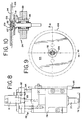
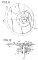
- FIGs. 9, 10, 11 and 12 illustrate the turntable assembly 24.
- a turntable spindle 87 is rotatably mounted within a sleeve 88 secured to a horizontal member 89 of the support structure 23.
- a table top or turntable 91 is secured to the spindle 87.
- a mounting bolt 92 will directly secure a plate clamp 93 (Figs. 11, 12 and 15) or a cam 94 (Figs. 9 and 10) to rotate with the spindle 87.
- the plate clamp approach it clamps down the cam to hold the blade securely and flatly.
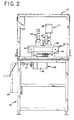
- a suitable motor 95 (Fig. 2) during the honing or grinding procedure.
- an encoder 96 and an encoder mounting bracket 97 (Fig. 15) are provided.
- a manual crank arrangement whereby a proper starting point for the honing or grinding operation can be manually located.
- a bevel gear 98 and an associated bevel pinion 99 are shown.
- Drive shaft 101 is shown mounted within a pillow block 102, and a crank 103 and handle 104 are mounted for driving engagement with the drive shaft 101 as desired.
- Motor 95 will rotate the drive shaft through a suitable drive arrangement including sprocket 105.
- FIGs. 9 and 10 illustrate an arrangement wherein a circular blade 106 is to be handled in accordance with the present invention.
- the blade is placed upon the turntable 91.
- a cam pilot 107 is positioned between this blade and the circular cam 94 that is of the proper size for blade 106.
- Assembly preferably includes the use of one or more dowels 108 and screws 109.
- Figs. 11 and 12 illustrate a suitable arrangement for mounting a blade which has a relatively wide mounting opening and has a peripheral cutting surface that is of a generally involute shape.
- a spacer plate 111 is secured to the turntable 91, such as by the use of a dowel 108.
- the involute blade 112 is sandwiched between this spacer plate and an involute cam 113 in association with the plate clamp 93 and one or more drive pins 114.
- this large involute blade and especially its generally concave body is closely secured between the surfaces of the spacer plate 111 and of the involute cam 113 in order to thereby securely hold the blade to maintain flatness of the blade.
- Particularly important to this desired flatness is having each cutting edge of the blade lie substantially parallel to a given plane or angled surface in order to thereby effect a honing or grinding that is flat and of uniform width along the length of the involute cutting edge.
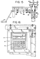
- Figs. 13 and 14 provide further details of the relationship between the cam and cam follower(s) and between the honing wheel(s) and the peripheral edges of the blade being honed or ground.
- Illustrated blade 112 has a flat top surface or land width 115 which is engaged by the honing or grinding wheel 76.
- the honing or grinding wheel 61 engages the primary bevel surface 116 of the blade 112. Virtually all of any burr formation made in connection with honing of the primary bevel surface will be removed during honing of the top flat surface 115.
- the primary angle is the angle defined between the top flat surface 115 and the primary bevel surface 116. It will be appreciated that cam follower 74 and cam follower 122 engage and rotate along a cam surface 117 of the cam 113; of course, this illustrated cam surface 117 is curved in that it has a curved profile in the horizontal orientation as shown in the drawings.
- a two-way valve as previously identified biases the cam followers 74 and 122 onto the cam surface 117.
- This biassing action will include, at least in the case of a non-circular blade, both extension and retraction of the cylinder rod 49.
- the extension is due primarily to the hydraulic pressure imparted by the cylinder rod by the two-way fluid cylinder 48, and the retraction is due primarily to the overcoming of that hydraulic pressure when the profile of the cam surface so dictates, such as when it is in a mode of increasing radius length.
- Fig. 16 illustrates a typical control panel and display which can be provided for controlling and monitoring the rotation of the turntable assembly 24 and the extension and retraction of the two-way fluid cylinders 48 and/or 53 and of the air cylinders 68 and 81.
- Control panel 31 includes a plurality of control keys 119, as well as a display 121. By activating one or more of the keys 119, the operator selects one of the pre-programmed control patterns that had been previously entered into memory. For example, the operator could enter a proper code for the particular type of blade being honed, ground or sharpened. In a typical application, the operator will also "zero" the blade to the designated starting point for the program. This can be achieved, for example, by turning the handle 104 and thus the turntable assembly 24 until the blade is at the designated starting point. This can be signalled, for example, by the lighting of a light or by a prompt on the display 121 or the like.
- the program in conjunction with the engagement between the cam follower(s) and cam when appropriate, controls movement of the honing wheel(s).
- This movement includes following the profile of all or substantially all of the cutting surface of the blade being honed or ground. In the case of non-circular blades, this movement also will typically include axial extension and retraction of the rotating honing wheel(s) so as to "dock” and “undock” the grinding wheels from the cutting edge being honed or ground.
- the honing wheel 76 of the deburring spindle assembly 28 retracts axially to move out of engagement with the top flat surface 115 at about the same time that the surface 115 ends on a typical involute blade. Conversely, axial extension occurs in order to dock the wheel 76 onto the top flat surface 115 at or substantially at the beginning of the surface on a typical involute blade.
- reverse movements will generally be required in order to dock and undock.
- a typical manner by which the rotation position of the blade can be tracked is through the use of a pulse generator in connection with the motor 95.
- the command to dock the honing wheel(s) can occur after a given number of generated pulses beyond the zero setting, and the honing wheel(s) will be undocked after an additional given number of pulses have been generated.
- the appropriate number of pulses in each instance will be determined according to the pre-programmed specifics for each type of slicer blade.
Landscapes
- Engineering & Computer Science (AREA)
- Mechanical Engineering (AREA)
- Finish Polishing, Edge Sharpening, And Grinding By Specific Grinding Devices (AREA)
Applications Claiming Priority (2)
| Application Number | Priority Date | Filing Date | Title |
|---|---|---|---|
| US370722 | 1989-06-23 | ||
| US08/370,722 US5609512A (en) | 1995-01-09 | 1995-01-09 | Method and apparatus for off-line honing of slicer blades |
Publications (1)
| Publication Number | Publication Date |
|---|---|
| EP0724931A1 true EP0724931A1 (de) | 1996-08-07 |
Family
ID=23460891
Family Applications (1)
| Application Number | Title | Priority Date | Filing Date |
|---|---|---|---|
| EP96300121A Withdrawn EP0724931A1 (de) | 1995-01-09 | 1996-01-08 | Off-line Honen von Aufschnitt-Schneidemaschine-Messern |
Country Status (6)
| Country | Link |
|---|---|
| US (1) | US5609512A (de) |
| EP (1) | EP0724931A1 (de) |
| JP (1) | JPH08229803A (de) |
| AU (1) | AU689987B2 (de) |
| CA (1) | CA2166052A1 (de) |
| NZ (1) | NZ280791A (de) |
Cited By (7)
| Publication number | Priority date | Publication date | Assignee | Title |
|---|---|---|---|---|
| US7464632B2 (en) | 2006-02-07 | 2008-12-16 | Premark Feg L.L.C. | Product fence for a food slicer |
| US7549363B2 (en) | 2005-08-26 | 2009-06-23 | Premark Feg L.L.C. | Product table for a food slicer with hollow peripheral reinforcements |
| US7637191B2 (en) | 2005-08-26 | 2009-12-29 | Premark Feg L.L.C. | Product table lock for a food slicer |
| US7832317B2 (en) | 2005-08-26 | 2010-11-16 | Premark Feg L.L.C. | Gage plate alignment mechanism and method for a food slicer |
| US8043142B2 (en) | 2005-08-26 | 2011-10-25 | Premark Feg L.L.C. | Sharpener carried by the product table of a food slicer |
| CN105415125A (zh) * | 2015-10-29 | 2016-03-23 | 燕山大学 | 一种适用于精整机组的被动式带钢边部修磨装置 |
| CN107009241A (zh) * | 2017-05-18 | 2017-08-04 | 南安市蒂巧工艺品有限公司 | 一种用于打磨建筑石材且具有单边倒角打磨功能的打磨机 |
Families Citing this family (17)
| Publication number | Priority date | Publication date | Assignee | Title |
|---|---|---|---|---|
| US5863238A (en) * | 1996-08-30 | 1999-01-26 | Felste Co., Inc. | Cob cutter blade honing device |
| AUPQ453499A0 (en) | 1999-12-08 | 2000-01-06 | Herbert Mcivor Holdings Pty Ltd | A system and method for automatically logging article use and an article adapted for such |
| US6371835B1 (en) | 1999-12-23 | 2002-04-16 | Kraft Foods, Inc. | Off-line honing of slicer blades |
| US6416394B1 (en) | 2000-03-22 | 2002-07-09 | Michael Hacikyan | Planar/grinder for glass |
| US6878035B2 (en) * | 2002-03-22 | 2005-04-12 | Darex Corporation | Tool sharpener |
| US7123960B2 (en) * | 2003-12-22 | 2006-10-17 | Cardiac Pacemakers, Inc. | Method and system for delivering cardiac resynchronization therapy with variable atrio-ventricular delay |
| US20070142959A1 (en) * | 2005-12-19 | 2007-06-21 | Rummel Samuel A | Food product slicer with automatic indication of when to sharpen knife |
| US7487702B2 (en) * | 2005-12-19 | 2009-02-10 | Premark Feg L.L.C. | Food product slicer with removable ring guard cover |
| US7134937B1 (en) | 2005-12-19 | 2006-11-14 | Premark Feg L.L.C. | Food product slicer with knife sharpener and associated knife guard |
| US8220383B2 (en) | 2008-04-15 | 2012-07-17 | Premark Feg L.L.C. | Food product slicer with timed sharpening operation |
| EP3369526B1 (de) * | 2015-10-26 | 2020-11-18 | Hitachi Metals, Ltd. | Pulverformkantenbearbeitungsvorrichtung und pulverformkantenbearbeitungsverfahren |
| USD870165S1 (en) | 2018-04-03 | 2019-12-17 | Michael Hacikyan | Glass grinding apparatus |
| US11203096B2 (en) | 2018-04-03 | 2021-12-21 | Michael Hacikyan | Glass grinding apparatus |
| CN109352470A (zh) * | 2018-11-29 | 2019-02-19 | 李配灯 | 一种弧面抛光装置 |
| CN112338699B (zh) * | 2020-10-30 | 2021-11-19 | 安徽龙波电气有限公司 | 用于断路器外壳加工用毛刺处理设备 |
| DE102022112000A1 (de) * | 2022-05-12 | 2023-11-16 | Dipl.Ing. S c h i n d l e r & Wagner GmbH & Co KG | Vorrichtung zum Schäfen und Verfahren zum Betrieb der Vorrichtung |
| CN117000642B (zh) * | 2023-09-26 | 2023-12-05 | 江苏德励达新材料股份有限公司 | 一种聚氨酯板材切割毛刺清理装置 |
Citations (5)
| Publication number | Priority date | Publication date | Assignee | Title |
|---|---|---|---|---|
| US2978848A (en) * | 1957-07-17 | 1961-04-11 | Armour & Co | Grinder for involute bacon knife |
| US3820289A (en) * | 1972-06-23 | 1974-06-28 | Speedco Inc | Knife sharpener |
| DE2620837A1 (de) * | 1976-05-11 | 1978-01-12 | Maier & Soehne Unitas | Messerhalter zum festlegen am support einer schleifmaschine mit schleifscheibe |
| SU965730A1 (ru) * | 1981-02-12 | 1982-10-15 | Предприятие П/Я Г-4086 | Устройство дл шлифовани кромок пластин |
| GB2238494A (en) * | 1989-12-01 | 1991-06-05 | Gd Spa | Grinding device for sharpening a rotary blade |
Family Cites Families (15)
| Publication number | Priority date | Publication date | Assignee | Title |
|---|---|---|---|---|
| US700293A (en) * | 1901-04-09 | 1902-05-20 | Otto Becker | Machine for grinding knives, principally those of sausage-machines or the like. |
| US1522109A (en) * | 1921-03-28 | 1925-01-06 | John C Fiddyment | Means for sharpening cutting tools |
| FR1588348A (de) * | 1968-10-14 | 1970-04-10 | ||
| US3813818A (en) * | 1972-10-12 | 1974-06-04 | Toyo Kogyo Co | Profile grinder |
| US4040313A (en) * | 1975-12-29 | 1977-08-09 | William John Lustgraaf | Precision circular saw blade grinding machine |
| US4365301A (en) * | 1980-09-12 | 1982-12-21 | The United States Of America As Represented By The United States Department Of Energy | Positional reference system for ultraprecision machining |
| DE3035660C2 (de) * | 1980-09-20 | 1982-10-21 | Flachglas AG, 8510 Fürth | Beschickwagen für eine Anlage zum Randschleifen von Glasscheiben |
| US4672777A (en) * | 1986-03-06 | 1987-06-16 | Albert Dunkin | Knife sharpening device |
| US4829721A (en) * | 1987-09-14 | 1989-05-16 | Hansaloy Corporation | Honing apparatus for bun slicing machines |
| US5117590A (en) * | 1988-08-12 | 1992-06-02 | Shin-Etsu Handotai Co., Ltd. | Method of automatically chamfering a wafer and apparatus therefor |
| US4976070A (en) * | 1989-09-12 | 1990-12-11 | Anthony Palazzola | Adjustable cam |
| US5097634A (en) * | 1989-12-08 | 1992-03-24 | Hulme Jack R | Tool grinder apparatus and method |
| US5142947A (en) * | 1991-07-30 | 1992-09-01 | Wang Tian Wang | Adjustable motor-operated circular saw sharpener |
| US5320014A (en) * | 1992-10-29 | 1994-06-14 | Oscar Mayer Foods Corporation | Yield improving continuous food slicing method and apparatus |
| FR2699445B1 (fr) * | 1992-12-18 | 1995-03-03 | Essilor Int | Procédé pour le contrôle sur une meuleuse de l'adéquation, à une monture de lunettes, d'un verre à meuler. |
-
1995
- 1995-01-09 US US08/370,722 patent/US5609512A/en not_active Expired - Lifetime
- 1995-12-22 CA CA002166052A patent/CA2166052A1/en not_active Abandoned
-
1996
- 1996-01-08 NZ NZ280791A patent/NZ280791A/en unknown
- 1996-01-08 EP EP96300121A patent/EP0724931A1/de not_active Withdrawn
- 1996-01-08 AU AU40855/96A patent/AU689987B2/en not_active Ceased
- 1996-01-09 JP JP8001212A patent/JPH08229803A/ja active Pending
Patent Citations (5)
| Publication number | Priority date | Publication date | Assignee | Title |
|---|---|---|---|---|
| US2978848A (en) * | 1957-07-17 | 1961-04-11 | Armour & Co | Grinder for involute bacon knife |
| US3820289A (en) * | 1972-06-23 | 1974-06-28 | Speedco Inc | Knife sharpener |
| DE2620837A1 (de) * | 1976-05-11 | 1978-01-12 | Maier & Soehne Unitas | Messerhalter zum festlegen am support einer schleifmaschine mit schleifscheibe |
| SU965730A1 (ru) * | 1981-02-12 | 1982-10-15 | Предприятие П/Я Г-4086 | Устройство дл шлифовани кромок пластин |
| GB2238494A (en) * | 1989-12-01 | 1991-06-05 | Gd Spa | Grinding device for sharpening a rotary blade |
Cited By (7)
| Publication number | Priority date | Publication date | Assignee | Title |
|---|---|---|---|---|
| US7549363B2 (en) | 2005-08-26 | 2009-06-23 | Premark Feg L.L.C. | Product table for a food slicer with hollow peripheral reinforcements |
| US7637191B2 (en) | 2005-08-26 | 2009-12-29 | Premark Feg L.L.C. | Product table lock for a food slicer |
| US7832317B2 (en) | 2005-08-26 | 2010-11-16 | Premark Feg L.L.C. | Gage plate alignment mechanism and method for a food slicer |
| US8043142B2 (en) | 2005-08-26 | 2011-10-25 | Premark Feg L.L.C. | Sharpener carried by the product table of a food slicer |
| US7464632B2 (en) | 2006-02-07 | 2008-12-16 | Premark Feg L.L.C. | Product fence for a food slicer |
| CN105415125A (zh) * | 2015-10-29 | 2016-03-23 | 燕山大学 | 一种适用于精整机组的被动式带钢边部修磨装置 |
| CN107009241A (zh) * | 2017-05-18 | 2017-08-04 | 南安市蒂巧工艺品有限公司 | 一种用于打磨建筑石材且具有单边倒角打磨功能的打磨机 |
Also Published As
| Publication number | Publication date |
|---|---|
| AU4085596A (en) | 1996-07-18 |
| US5609512A (en) | 1997-03-11 |
| CA2166052A1 (en) | 1996-07-10 |
| JPH08229803A (ja) | 1996-09-10 |
| NZ280791A (en) | 1997-06-24 |
| AU689987B2 (en) | 1998-04-09 |
Similar Documents
| Publication | Publication Date | Title |
|---|---|---|
| US5609512A (en) | Method and apparatus for off-line honing of slicer blades | |
| CA2151904C (en) | Ring guard for food slicing machine blade | |
| US3821915A (en) | Fiber cutting apparatus with self-contained blade sharpener | |
| CA2329161C (en) | Off-line honing of slicer blades | |
| US4829721A (en) | Honing apparatus for bun slicing machines | |
| WO2007113510A1 (en) | Tool holding jig | |
| US4134235A (en) | One chuck grinding apparatus for end milling cutters and the like | |
| EP3657952B1 (de) | Schneidevorrichtung zum beschneiden von fleischstücken, verarbeitungssystem mit einer solchen schneidevorrichtung und entsprechende betriebs- und anwendungsverfahren | |
| US6058806A (en) | Automatic chain saw sharpener | |
| US20180050461A1 (en) | Apparatus and method for spirally slicing meat | |
| US5480345A (en) | Knife sharpener | |
| US5586929A (en) | Precision cut off machine | |
| CN208629057U (zh) | 自动磨刀机 | |
| GB2274801A (en) | Sheet cutting apparatus | |
| CN101247929B (zh) | 由食品切片机的食品工作台承载的磨具 | |
| RU201146U1 (ru) | Устройство для ручной заточки ножей | |
| JP2857059B2 (ja) | 面取り装置 | |
| US3162987A (en) | Method of resharpening cutter blades having a contoured cutting edge | |
| US4383459A (en) | Meat cutter for slicing soft-meat logs | |
| GB2061780A (en) | Involute knife sharpener | |
| CN118789373B (zh) | 一种刀剪刃口的自动化磨削装置 | |
| CN108655834A (zh) | 自动磨刀机 | |
| GB2091144A (en) | A blade grinder | |
| CN223028629U (zh) | 一种滚齿机刀架角度调整机构 | |
| JPH0569288A (ja) | 刃物およびその研削装置 |
Legal Events
| Date | Code | Title | Description |
|---|---|---|---|
| PUAI | Public reference made under article 153(3) epc to a published international application that has entered the european phase |
Free format text: ORIGINAL CODE: 0009012 |
|
| AK | Designated contracting states |
Kind code of ref document: A1 Designated state(s): AT BE CH DE DK ES FR GB GR IE IT LI LU MC NL PT SE |
|
| AX | Request for extension of the european patent |
Free format text: LT PAYMENT 960113;LV PAYMENT 960113;SI PAYMENT 960113 |
|
| RAX | Requested extension states of the european patent have changed |
Free format text: LT PAYMENT 960113;LV PAYMENT 960113;SI PAYMENT 960113 |
|
| RIN1 | Information on inventor provided before grant (corrected) |
Inventor name: FLISRAM, DENNIS G. Inventor name: GUNDLACH, LARRY C. Inventor name: SKAAR, GARY R. Inventor name: HOLMES, TERRY L. |
|
| 17P | Request for examination filed |
Effective date: 19961219 |
|
| GRAG | Despatch of communication of intention to grant |
Free format text: ORIGINAL CODE: EPIDOS AGRA |
|
| 17Q | First examination report despatched |
Effective date: 19990421 |
|
| GRAG | Despatch of communication of intention to grant |
Free format text: ORIGINAL CODE: EPIDOS AGRA |
|
| GRAG | Despatch of communication of intention to grant |
Free format text: ORIGINAL CODE: EPIDOS AGRA |
|
| GRAH | Despatch of communication of intention to grant a patent |
Free format text: ORIGINAL CODE: EPIDOS IGRA |
|
| STAA | Information on the status of an ep patent application or granted ep patent |
Free format text: STATUS: THE APPLICATION IS DEEMED TO BE WITHDRAWN |
|
| 18D | Application deemed to be withdrawn |
Effective date: 19991130 |