EP0724924A2 - Tool holder, particularly quick-release chuck - Google Patents
Tool holder, particularly quick-release chuck Download PDFInfo
- Publication number
- EP0724924A2 EP0724924A2 EP96106069A EP96106069A EP0724924A2 EP 0724924 A2 EP0724924 A2 EP 0724924A2 EP 96106069 A EP96106069 A EP 96106069A EP 96106069 A EP96106069 A EP 96106069A EP 0724924 A2 EP0724924 A2 EP 0724924A2
- Authority
- EP
- European Patent Office
- Prior art keywords
- housing
- tool holder
- head
- tube
- locking ring
- Prior art date
- Legal status (The legal status is an assumption and is not a legal conclusion. Google has not performed a legal analysis and makes no representation as to the accuracy of the status listed.)
- Granted
Links
- 239000002826 coolant Substances 0.000 claims abstract description 27
- 238000006073 displacement reaction Methods 0.000 claims abstract description 15
- 230000005540 biological transmission Effects 0.000 claims abstract description 4
- 238000009423 ventilation Methods 0.000 claims description 5
- 230000006835 compression Effects 0.000 description 10
- 238000007906 compression Methods 0.000 description 10
- 210000002435 tendon Anatomy 0.000 description 7
- 230000009471 action Effects 0.000 description 3
- 230000004323 axial length Effects 0.000 description 3
- 230000008859 change Effects 0.000 description 2
- 230000002093 peripheral effect Effects 0.000 description 2
- 238000007789 sealing Methods 0.000 description 2
- 230000006978 adaptation Effects 0.000 description 1
- 230000000295 complement effect Effects 0.000 description 1
- 238000010276 construction Methods 0.000 description 1
- 238000011161 development Methods 0.000 description 1
- 230000018109 developmental process Effects 0.000 description 1
- 238000005553 drilling Methods 0.000 description 1
- 230000001771 impaired effect Effects 0.000 description 1
- 239000012535 impurity Substances 0.000 description 1
- 238000003780 insertion Methods 0.000 description 1
- 230000037431 insertion Effects 0.000 description 1
- 239000002184 metal Substances 0.000 description 1
- 230000009467 reduction Effects 0.000 description 1
- 230000007704 transition Effects 0.000 description 1
Images
Classifications
-
- B—PERFORMING OPERATIONS; TRANSPORTING
- B23—MACHINE TOOLS; METAL-WORKING NOT OTHERWISE PROVIDED FOR
- B23Q—DETAILS, COMPONENTS, OR ACCESSORIES FOR MACHINE TOOLS, e.g. ARRANGEMENTS FOR COPYING OR CONTROLLING; MACHINE TOOLS IN GENERAL CHARACTERISED BY THE CONSTRUCTION OF PARTICULAR DETAILS OR COMPONENTS; COMBINATIONS OR ASSOCIATIONS OF METAL-WORKING MACHINES, NOT DIRECTED TO A PARTICULAR RESULT
- B23Q1/00—Members which are comprised in the general build-up of a form of machine, particularly relatively large fixed members
- B23Q1/0009—Energy-transferring means or control lines for movable machine parts; Control panels or boxes; Control parts
- B23Q1/0018—Energy-transferring means or control lines for movable machine parts; Control panels or boxes; Control parts comprising hydraulic means
- B23Q1/0027—Energy-transferring means or control lines for movable machine parts; Control panels or boxes; Control parts comprising hydraulic means between moving parts between which an uninterrupted energy-transfer connection is maintained
- B23Q1/0036—Energy-transferring means or control lines for movable machine parts; Control panels or boxes; Control parts comprising hydraulic means between moving parts between which an uninterrupted energy-transfer connection is maintained one of those parts being a tool
-
- B—PERFORMING OPERATIONS; TRANSPORTING
- B23—MACHINE TOOLS; METAL-WORKING NOT OTHERWISE PROVIDED FOR
- B23B—TURNING; BORING
- B23B31/00—Chucks; Expansion mandrels; Adaptations thereof for remote control
- B23B31/02—Chucks
- B23B31/08—Chucks holding tools yieldably
- B23B31/083—Chucks holding tools yieldably axially
-
- Y—GENERAL TAGGING OF NEW TECHNOLOGICAL DEVELOPMENTS; GENERAL TAGGING OF CROSS-SECTIONAL TECHNOLOGIES SPANNING OVER SEVERAL SECTIONS OF THE IPC; TECHNICAL SUBJECTS COVERED BY FORMER USPC CROSS-REFERENCE ART COLLECTIONS [XRACs] AND DIGESTS
- Y10—TECHNICAL SUBJECTS COVERED BY FORMER USPC
- Y10T—TECHNICAL SUBJECTS COVERED BY FORMER US CLASSIFICATION
- Y10T279/00—Chucks or sockets
- Y10T279/17—Socket type
- Y10T279/17017—Self-centering of floating
-
- Y—GENERAL TAGGING OF NEW TECHNOLOGICAL DEVELOPMENTS; GENERAL TAGGING OF CROSS-SECTIONAL TECHNOLOGIES SPANNING OVER SEVERAL SECTIONS OF THE IPC; TECHNICAL SUBJECTS COVERED BY FORMER USPC CROSS-REFERENCE ART COLLECTIONS [XRACs] AND DIGESTS
- Y10—TECHNICAL SUBJECTS COVERED BY FORMER USPC
- Y10T—TECHNICAL SUBJECTS COVERED BY FORMER US CLASSIFICATION
- Y10T408/00—Cutting by use of rotating axially moving tool
- Y10T408/44—Cutting by use of rotating axially moving tool with means to apply transient, fluent medium to work or product
- Y10T408/45—Cutting by use of rotating axially moving tool with means to apply transient, fluent medium to work or product including Tool with duct
-
- Y—GENERAL TAGGING OF NEW TECHNOLOGICAL DEVELOPMENTS; GENERAL TAGGING OF CROSS-SECTIONAL TECHNOLOGIES SPANNING OVER SEVERAL SECTIONS OF THE IPC; TECHNICAL SUBJECTS COVERED BY FORMER USPC CROSS-REFERENCE ART COLLECTIONS [XRACs] AND DIGESTS
- Y10—TECHNICAL SUBJECTS COVERED BY FORMER USPC
- Y10T—TECHNICAL SUBJECTS COVERED BY FORMER US CLASSIFICATION
- Y10T408/00—Cutting by use of rotating axially moving tool
- Y10T408/73—Tool or tool-support with torque-applying spline
Definitions
- the invention relates to a tool holder, in particular quick-change chuck, of the type mentioned in the preamble of claim 1.
- a tool holder of this type is known (DE-A-39 02 559), in which a tubular part serving as the central coolant guide is fixedly attached to the housing and extends through the receptacle and is movable together with the housing as a unit relative to the receptacle is.
- the pipe section must be sealed off from the head at various points.
- the pressure column of the pressurized coolant is also moved during the relative displacement between the head and the housing. Because of this moving pressure column of the coolant, there are sometimes uncontrolled relative displacements between the housing and the head.
- the tool holder with this coolant guide is relatively complicated and expensive. Its assembly is complex.
- the invention has for its object to provide a tool holder, in particular a quick-change chuck of the type mentioned in the preamble of claim 1, which eliminates these disadvantages.
- the tool holder 9 shown in the drawings consists in particular of a quick-change chuck 10, preferably for thread cutting, thread forming or the like.
- the quick-change chuck 10 has a receptacle 11 and a housing 12.
- the receptacle 11 is set up at the upper end 13 in FIG. 1 for insertion into a machine spindle (not shown), tool holder or the like.
- a machine tool. B. is designed as a shaft, the od or the like. Can be received directly or with the interposition of an adaptation element in the machine spindle, not shown, tool holder and the like.
- the receptacle 11 has a head 14 which is provided with a cylinder wall 15, within which a coaxial cylindrical opening 16 is contained, which is open at the bottom in FIG. 1.
- the housing 12 is non-rotatable, but relatively displaceable, received and guided in the axial longitudinal direction in accordance with the longitudinal central axis 8.
- the housing 12 has an approximately inverted cup-shaped design and has in the lower part a cylinder wall 23 which encloses a coaxial cylindrical opening 24 which is open at the bottom in FIG. 1 and into which an only indicated conventional quick-change insert 26 can be inserted and can thus be coupled axially and in a torque-transmitting manner .
- the quick change insert 26 carries a tool 27, for example for thread cutting, thread forming or the like. suitable is.
- the axially positive locking and rotational driving of the quick-change insert 26 used takes place in the usual manner (DE-OS 39 02 559) via at least one retaining ball 28 which is held in a radial opening 25 of the cylinder wall 23 of the housing 12.
- the holding ball 28 engages in a form-fitting manner in an outer annular groove 7 of the quick-change insert 26.
- a plurality of holding balls 28 arranged at intervals in the circumferential direction can also be provided.
- the holding ball 28 is actuated by means of an outer actuating sleeve 17, which surrounds an outer sleeve 18 and is displaceable in the axial direction relative thereto.
- the outer sleeve 18 engages around the cylinder wall 23 and is firmly attached to it and firmly connected by means of a threaded screw 19, for example.
- a threaded screw 19 for example.
- the inner diameter of the outer sleeve 18 widens such that it surrounds the cylinder wall 15 of the head 14 with an upper cylindrical neck 20 to form an annular space 21 therebetween.
- An axial length compensation device 31 is contained in this annular space 21, which is effective axially between the housing 12 and the receptacle 11 and enables axial length compensation in the event of a relative displacement in both axial directions, thus under tension and pressure.
- the length compensation device 31 acts as a gate pressure booster with pressure in the axial direction according to FIG. 1 from top to bottom.
- the length compensation device 31 contains in the annular space 21 a single compression spring 32 for length compensation in one or in the other axial direction.
- the upper end of the compression spring 32 is supported on a ring 33 which is secured against displacement in FIG. 1 by a snap ring 34 on the receptacle 11.
- the ring 32 can also be shifted downward when the housing 12 is relatively displaced downward in FIG. 1.
- the ring 33 With a relative displacement of the housing 12 with the outer sleeve 18 in Fig. 1 upwards, the ring 33 remains as an abutment for the compression spring 32. This is the case if, for example, an axial pressure acts on the tool 27 from the machine spindle via the receptacle 11 during drilling and this is received by the compression spring 32 after the gate pressure booster has responded, since the receptacle 11 with the ring 33 is relative to the housing 12 in FIG. 1 is moved downward by compressing the compression spring 32.
- the head 14 is coupled to the housing 12 in the axial and circumferential directions via at least one driving body 36, which is arranged between the head 14 and the housing 12.
- the at least one driver body 36 is partially held in an associated longitudinal groove 37 of the head 14 and partially in an associated longitudinal groove 38 of the housing 12, so that the torque transmission can take place and the driver body 36 during the relative displacement between the head 14 and the housing 12 can roll, so that there is a smooth relative displacement.
- the at least one driver body 36 is arranged between the head 14 and the housing 12 with regard to its position in the longitudinal direction, i.e. in the direction approximately parallel to the longitudinal central axis 8, and by means of an elastic tendon 39 from the outside inwards a pressing force is applied, which holds the at least one driving body 36 in this position, ie prevents the driving body 36 in FIG. 1 from falling down in the longitudinal grooves 37, 38 and then during the relative displacement between the head 14 and the housing 12 can no longer roll.
- a considerable simplification is achieved in comparison with known tool holders, since in this way an otherwise necessary and inserted ball guide sleeve, in which the at least one driving body 36 is held in position, can be dispensed with.
- Ball guide sleeves are not only costly themselves, but they require correspondingly precisely machined guide surfaces for the balls of the ball guide sleeve on the head 14 and the housing 12. This special processing is also expensive. In addition, ball guide sleeves require a larger diameter of the tool holder. Finally, it has been shown that impurities can get into the area of a ball guide sleeve, which can then result in jamming in a relatively short time. These problems are also eliminated in the design mentioned, which makes a ball guide sleeve unnecessary.
- the longitudinal groove 37 provided for each driving body 36 in the head 14 is formed as a longitudinal slot 40 in the transverse direction within the cylinder wall 15 of the head 14.
- the at least one driver body 36 extends in the transverse direction through the associated longitudinal slot 40 in the head 14 and projects at least slightly beyond the outside 41 of the head 40 in the region of this longitudinal slot 40.
- the elastic tendon 39 consists in a particularly advantageous, simple manner of a circumferential tendon 42, which at least partially surrounds the head 14 on the outside 41 thereof in the region of the at least one entraining body 36 and engages the outside of the projecting part of the at least one entraining body 36 and there from pressure force directed inwards from outside.
- the peripheral tendon 42 is formed from an elastically resilient ring part, for example a ring or a cylinder sleeve, in particular made of metal. It is fixed in the axial longitudinal direction on the head 14, in particular on the outside 41 thereof.
- the circumferential tendon 42 is a closed ring part.
- the circumferential tendon 42 can instead be interrupted at one point in the axial longitudinal direction, e.g. slotted to be.
- the at least one longitudinal groove 38 of the housing 12 has a trapezoidal cross section that is symmetrical.
- the line of symmetry 46 runs within a diametral plane 47 and thus passes through the center of the housing 12.
- a further similar pair of longitudinal grooves 37 ', 38' with an associated driving body 36 ' is provided within this diametrical plane 47, which is diametrically opposite the pair of longitudinal grooves 37, 38 with driving body 36.
- two diametrically opposed longitudinal groove pairs 37 ′′, 38 ′′ with an associated driving body 36 ′′ or 37 ′′ ′′, 38 ′′ ′′ with an associated driving body 36 ′′ ′′ are present in the area of another diametrical plane 48.
- a total of four longitudinal grooves 37, 37 ', 37'',37''' distributed over the circumference are provided in the head 14 and, furthermore, four longitudinal grooves 38, 38 ', 38'',38''''distributed over the circumference are assigned.
- a drive body 36 or 36 'or 36''or36''' being present for each pair of longitudinal grooves. It is particularly important that the two diametrical planes 47 and 48 extend at an angle of approximately 60 ° and a complementary angle of approximately 120 ° to one another. This means that, for example, the two pairs of longitudinal grooves 37, 38 and 37 ′′, 38 ′′ (FIG.
- This last-mentioned circumferential region free of longitudinal grooves is provided, for example, between the two pairs of longitudinal grooves 37 ', 38' and 37 '', 38 '' or on the opposite side between the two pairs of longitudinal grooves 37, 38 and 37 ''',38'''.
- the longitudinal groove 37 and the three other similar longitudinal grooves 37 ', 37' ', 37' '' of the head 14 are all designed identically. They have two mutually opposite and mutually parallel flanks 49, 50 which each run within the plane of a secant 51 or 52, which are at a radial distance from the longitudinal central axis 8 and thus the center of the tool holder 9 and thus approximately parallel to one through the center pass through diametral plane 53.
- the at least one driving body 36 per pair of longitudinal grooves advantageously consists of a driving ball.
- the distance between the two flanks 49, 50 of the respective longitudinal groove 37, 37 ', 37' ', 37' '' of the head 14 corresponds approximately to the diameter of this driving ball or is at least slightly larger than this diameter.
- the driving body 36 ′′, 36 '' ' in particular the driving ball, is so loaded that it is pressed more inwards, under no circumstances can it move outwards under this load and thereby load the elastic peripheral tendon 42, for example.
- the driving bodies 36 ′′, 36 ′′ ′′ thus do not load the circumferential tensioning member 42 during this clockwise rotation and the forces acting in the direction of the arrows 55, 56, which can therefore be made very thin and elastic.
- a thin metallic cylinder sleeve is sufficient, which is mounted on the outside of the cylinder wall 15 of the head with a slight pretension in such a way that it encompasses the driving bodies 36, 36 ', 36' ', 36' '' which protrude slightly outwards and with which can act from the outside inward elastic force.
- the driving bodies 36, 36 'on the diametral plane 47 are acted upon by the flanks 49 of the longitudinal grooves 37, 37', likewise on the Driving bodies 36, 36 'act forces which are directed approximately at right angles to this flank 49 and to the plane of the secant 51 and go approximately through the center of the driving body 36, 36', in particular the driving ball, and in this connection with respect to the longitudinal groove 38, 38 'are effective on the outside in such a way that the respective driving body 36, 36' is thereby rather forced inwards and is in any case prevented from moving outwards and from applying force to the circumferential tensioning member 42.
- the individual driving bodies 36, 36 ', 36'',36''' in particular driving balls, can be arranged in a simple manner between the head 14 and the housing 12 with regard to the position in the longitudinal direction and via the circumferential tensioning member 42, for example in shape a thin metallic cylinder sleeve, from the outside inward, a pressing force is sufficient to hold the respective driving body in position in the associated pair of longitudinal grooves.
- the length compensation device 31 explained at the outset is located on the outside of the circumferential tensioning member 42, which contains an annular groove 60 on its outside at the lower end in FIG. 1, within which a plurality of balls 61 are supported with a circumferential part. Also contained in the annular space 21 is a support ring 62, which surrounds the circumferential tensioning member 42 and has an inclined surface 63 on one side, which is pressed by means of the compression spring 32 with its inclined surface 63 in the axial longitudinal direction, ie downward in FIG.
- an approximately cylindrical sleeve-shaped ball holder 64 is arranged, which rests against the outer sleeve 18 in an axial direction, namely downward in FIG. 1, to be precise an axial ring shoulder, which is formed in the transition region to the neck 20.
- the ball holder 64 contains in the upper area in FIG. 1 radially directed openings 65, for. B. holes in which the balls 61 are held.
- This end region containing the bores 65 is chamfered in such a way that it tapers upwards in FIG. 1, the helix angle being at least in that of the oblique surface 63 of the support ring 62 essentially corresponds.
- the support ring 62 is arranged on this beveled, facing end 87 of the ball holder 64, in such a way that the support ring 62 with its inclined surface 63 is in contact with the balls 61 which protrude at least slightly radially at this end 87.
- the tool holder 9 is also provided with an inner coolant guide, which is particularly simple in design, which is achieved in that the length compensation device 31 is displaced outwards and into the outer circumferential region of the cylinder wall 15.
- the quick-change chuck 10 has a central inner tube 66 which serves to guide the coolant and which is fastened to the receptacle 11 with an upper end in FIG. 1 and which extends from there into the coaxial cylinder opening 16 and into a central bore 67 of the housing 12 stretched in.
- the bore 67 contains an annular space 70 for the coolant which is sealed at both axial ends by means of sealing rings 68, 69 and is thus delimited on the inside by the tube 66 and on the outside by the bore 67.
- the annular space 70 is on the one hand via at least one channel 71 in the pipe 66, e.g. a hole in the pipe wall, with the interior 72 of the pipe 66 in connection.
- the annular space 70 is connected to channels 73, 74 in the housing 12, of which the channel 73 e.g. radial and channel 74 e.g. runs approximately axially parallel, with both channels 73, 74 extending essentially outside the center of the housing 12.
- the channel 74 leads to the coaxial cylindrical opening 24 of the housing 12.
- the free end of the tube 66 located at the bottom in FIG. 1 is closed, for example closed by a stopper. It extends through a central axial bore 75 through in the housing 12, which is larger in diameter and is designed, for example, as a threaded bore. The end of the tube 66 extends there into a space 76 which is formed in the interior of an approximately cup-shaped closure member 77 and is closed at the bottom. The end member 77 is screwed into the bore 75 with a pin and is thus fastened to the housing 12.
- the closure member 77 is surrounded by a locking ring 78 which is held axially displaceably in the cylindrical opening 24 of the housing 12 and is sealed in the circumferential direction with respect to the housing 12, in particular its cylinder wall 23, by means of a sealing ring 79.
- the terminating member 77 has at least one radially projecting projection 80 at the axial end, in particular an annular shoulder, the projection 80 serving as a stop for the locking ring 78 when the quick-change insert 26 is removed.
- the locking ring 78 has in association with it at one end at least one radially inwardly projecting stop 81, e.g. a stop shoulder. If the quick-change insert 26 is removed and thereby the locking ring 78 is released in the axial direction, which is pressed tightly against the facing end face of the quick-change insert via an end seal 82, the locking ring 78 is displaced downward in FIG.
- the coolant reaching the channel 74 is passed through channels of the closing member 77 and the locking ring 78 in Fig. 1 downward, so that it through the central opening in Quick change insert 26 and, for example, can pass through an opening in the tool 27.
- the locking ring 78 has at the upper end in FIG. 1 at least one transverse channel 84, for example a transverse groove, which is connected to the channel 74.
- the transverse channel 84 is connected to an annular space 85, which is formed on the circumferential side between the closure member 77 and the locking ring 78.
- the closure member 77 has at least one recess 86 or two diametrically opposite recesses of this type on the outside, the recess 86 being connected to the annular space 85 for the coolant guide.
- the coolant is e.g. introduced into the interior of the end 13 of the receptacle 11 and enters the interior 72 of the tube 66, from which it reaches the annular space 70 via the at least one channel 71 and from there via the channels 73, 74 to the at least one transverse channel 84 inner end of the locking ring 78. From at least one transverse channel 84, the coolant passes through the annular space 85 and the at least one recess 86, where it exits and enters an inner central opening of the quick-change insert 26.
- the closing member 77 and the locking ring 78 can be designed such that when the quick-change insert 26 is removed and the locking ring 78 is moved further downward, the coolant passage from the annular space 85 is blocked to the outside, so that no coolant can escape when the quick-change insert 26 is removed.
- the inner coolant guide described with the aid of the tube 26 fastened in the receptacle 11 is particularly simple and inexpensive. Since the pressure column of the pressurized coolant is not moved during a relative displacement between the housing 12 and the head 14, any falsification of the relative position between the head 14 and the housing 12 is excluded. Further is pressure relief achieved.
- the tool holder 9, in particular the quick-change chuck 10, is not equipped with the internal coolant guide described and is therefore particularly simple.
- the length compensation device 31 can also be omitted.
- the tool holder 9, in particular the quick-change chuck 10, is compact, enables a relatively small diameter, is as short as possible with regard to the axial length and is reliable in operation and not susceptible to faults, so that its function is not impaired even when dirt gets in, and is inexpensive and Can be produced inexpensively, so that it leads to a considerable reduction in costs compared to known quick-change chucks.
- a ventilation channel 29 is used in the housing 12, which here, for. B. consists of at least one radial channel which is guided outwards to a longitudinal groove 38 and thus via the longitudinal groove 38, furthermore the longitudinal groove 37 and the annular space 21 is vented.
- the ventilation channel 29 is in the inner region of the housing 12 in connection with a central space 30, which in turn communicates with the space 76 in the closure member 77. In an embodiment not shown, this can e.g.
- an annular space 88 is left between the terminating element 77 and the free end of the tube 66 extending into the latter, which provides the connection between the space 76 and the central space 30 and the ventilation duct 29 produces, so that the space 76 is thereby vented in a particularly simple manner.
Landscapes
- Engineering & Computer Science (AREA)
- Mechanical Engineering (AREA)
- Gripping On Spindles (AREA)
- Drilling And Boring (AREA)
Abstract
Description
Die Erfindung bezihet sich auf einen Werkzeughalter, insbesondere Schnellwechselfutter, der im Oberbegriff des Anspruchs 1 genannten Art.The invention relates to a tool holder, in particular quick-change chuck, of the type mentioned in the preamble of claim 1.
Es ist ein Werkzeughalter dieser Art bekannt (DE-A-39 02 559), bei dem am Gehäuse ein der zentralen Kühlmittelführung dienender Rohrteil fest angebracht ist, der sich durch die Aufnahme hindurch erstreckt und zusammen mit dem Gehäuse als eine Einheit relativ zur Aufnahme beweglich ist. Der Rohrteil muß gegenüber dem Kopf an verschiedenen Stellen abgedichtet sein. Es besteht der Nachteil, daß bei der Relativverschiebung zwischen dem Kopf und dem Gehäuse die Drucksäule des unter Druck stehenden Kühlmittels mitbewegt wird. Aufgrund dieser mitbewegten Drucksäule des Kühlmittels ergeben sich mitunter unkontrollierte Relativverschiebungen zwischen dem Gehäuse und dem Kopf. Der Werkzeughalter mit dieser Kühlmittelführung ist relativ kompliziert und kostenaufwendig. Seine Montage ist aufwendig.A tool holder of this type is known (DE-A-39 02 559), in which a tubular part serving as the central coolant guide is fixedly attached to the housing and extends through the receptacle and is movable together with the housing as a unit relative to the receptacle is. The pipe section must be sealed off from the head at various points. There is the disadvantage that the pressure column of the pressurized coolant is also moved during the relative displacement between the head and the housing. Because of this moving pressure column of the coolant, there are sometimes uncontrolled relative displacements between the housing and the head. The tool holder with this coolant guide is relatively complicated and expensive. Its assembly is complex.
Der Erfindung liegt die Aufgabe zugrunde, einen Werkzeughalter, insbesondere ein Schnellwechselfutter, der im Oberbegriff des Anspruchs 1 genannten Art zu schaffen, der diese Nachteile beseitigt.The invention has for its object to provide a tool holder, in particular a quick-change chuck of the type mentioned in the preamble of claim 1, which eliminates these disadvantages.
Die Aufgabe ist bei einem Werkzeughalter, insbesondere Schnellwechselfutter, der im Oberbegriff des Anspruchs 1 genannten Art gemäß der Erfindung durch die Merkmale im Kennzeichnungsteil des Anspruchs 1 gelöst. Vorteilhafte Weiterbildungen dazu enthalten die Ansprüche 2 bis 8. Dadurch, daß das der inneren Kühlmittelführung durch den Werkzeughalter dienende Rohr fest am Kopf angebracht ist, wird bei der Relativverschiebung zwischen Kopf und Gehäuse nicht die Drucksäule des unter Druck stehenden Kühlmittels mit bewegt. Etwaige unkontrollierte Relativverschiebungen zwischen Gehäuse und Kopf, die auf eine mitbewegte Drucksäule des Kühlmittels evtl. zurückzuführen sind, sind damit völlig ausgeschaltet. Die Kühlmittelführung mit den einzelnen Komponenten ist einfacher, kostengünstiger und erlaubt eine kürzere Bauweise des Werkzeughalters, der zugleich auch im Durchmesser kompakter gestaltet werden kann. Der Werkzeughalter ist ferner leichter zu montieren. Von Vorteil ist ferner, daß bei dieser Konzeption bei nicht eingesetztem Schnellwechseleinsatz zwischen dem Abschlußglied und dem Sperring ein selbsttätiger Verschluß der Kühlmittelkanäle konstruktiv verwirklichbar ist, so daß bei entnommenem Schnellwechselweinsatz kein Kühlmittel austreten kann.The object is achieved in a tool holder, in particular quick-change chuck, of the type mentioned in the preamble of claim 1 according to the invention by the features in the characterizing part of claim 1. Advantageous further developments include
Weitere Einzelheiten, insbesondere Erfindungsmerkmale, sowie Vorteile der Erfindung ergeben sich aus der nachfolgenden Beschreibung.Further details, in particular features of the invention, and advantages of the invention will become apparent from the description below.
Der vollständige Wortlaut der Ansprüche ist vorstehend allein zur Vermeidung unnötiger Wiederholungen nicht wiedergegeben, sondern statt dessen lediglich durch Nennung der Anspruchsnummern darauf Bezug genommen, wodurch jedoch alle diese Anspruchsmerkmale als an dieser Stelle ausdrücklich und erfindungswesentlich offenbart zu gelten haben. Dabei sind alle in der vorstehenden und folgenden Beschreibung erwähnten Merkmale sowie auch die allein aus der Zeichnung entnehmbaren Merkmale weitere Bestandteile, auch wenn diese nicht besonders hervorgehoben und insbesondere nicht in den Ansprüchen erwähnt sind.The full wording of the claims is not reproduced above solely in order to avoid unnecessary repetition, but instead is referred to only by mentioning the claim numbers, whereby all these features of the claim are to be regarded as being explicitly disclosed here and essential to the invention. All of the features mentioned in the above and the following description and also the features that can be seen solely from the drawing are further components, even if these are not particularly emphasized and in particular are not mentioned in the claims.
Die Erfindung ist nachfolgend anhand eines in den Zeichnungen gezeigten Ausführungsbeispieles näher erläutert.
Es zeigen:
- Fig. 1
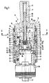
- einen schematischen axialen Längsschnitt eines Werkzeughalters,
- Fig. 2
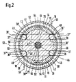
- einen schematischen Schnitt entlang der Linie II-II in Fig. 1.
Show it:
- Fig. 1
- 2 shows a schematic axial longitudinal section of a tool holder,
- Fig. 2
- a schematic section along the line II-II in Fig. 1st
Der in den Zeichnungen gezeigte Werkzeughalter 9 besteht insbesondere aus einem Schnellwechselfutter 10, vorzugsweise zum Geindeschneiden, Gewindeformen od. dgl.. Das Schnellwechselfutter 10 weist eine Aufnahme 11 und ein Gehäuse 12 auf. Die Aufnahme 11 ist am in Fig. 1 oberen Ende 13 zum Einsetzen in eine nicht gezeigte Maschinenspindel, Werkzeugaufnahme od. dgl. einer Werkzeugmaschine eingerichtet, wobei dieses Ende 13 z. B. als Schaft ausgebildet ist, der unmittelbar oder unter Zwischenfügung eines Anpassungselements in der nicht gezeigten Maschinenspindel, Werkzeugaufnahme od. dgl. aufnehmbar und mit dieser zur Drehmitnahme koppelbar ist.The tool holder 9 shown in the drawings consists in particular of a quick-
Am gegenüberliegenden, in Fig. 1 unten befindlichen Ende weist die Aufnahme 11 einen Kopf 14 auf, der mit einer Zylinderwandung 15 versehen ist, innerhalb der eine koaxiale zylindrische Öffnung 16 enthalten ist, die in Fig. 1 nach unten hin offen ist. In dieser Öffnung 16 ist das Gehäuse 12 undrehbar, jedoch in axialer Längsrichtung entsprechend der Längsmittelachse 8 relativverschiebbar, aufgenommen und geführt.At the opposite end, which is at the bottom in FIG. 1, the
Das Gehäuse 12 ist etwa umgekehrt topfförmig gestaltet und weist im unteren Teil eine Zylinderwandung 23 auf, die eine koaxiale zylindrische und in Fig. 1 nach unten offene Öffnung 24 umschließt, in die ein nur angedeuteter üblicher Schnellwechseleinsatz 26 einsetzbar und damit axial und drehmomentübertragend kuppelbar ist. Der Schnellwechseleinsatz 26 trägt ein Werkzeug 27, das z.B. zum Gewindeschneiden, Gewindeformen od.dgl. geeignet ist. Die axiale formschlüssige Arretierung und Drehmitnahme des eingesetzten Schnellwechseleinsatzes 26 erfolgt in üblicher Weise (DE-OS 39 02 559) über mindestens eine Haltekugel 28, die in einer Radialöffnung 25 der Zylinderwandung 23 des Gehäuses 12 gehalten ist. Die Haltekugel 28 greift formschlüssig in eine äußere Ringnut 7 des Schnellwechseleinsatzes 26 ein. Es können auch mehrere, in Umfangsrichtung in Abständen angeordnete Haltekugeln 28 vorgesehen sein.The
Die Haltekugel 28 wird mittels einer äußeren Betätigungshülse 17 betätigt, die eine Außenhülse 18 umgibt und relativ dazu in Axialrichtung verschiebbar ist. Die Außenhülse 18 umgreift die Zylinderwandung 23 und ist auf dieser fest aufgesetzt und mittels z.B. einer Gewindeschraube 19 fest verbunden. In Fig. 1 nach oben hin erweitert sich der Innendurchmesser der Außenhülse 18 derart, daß diese mit einem oberen zylindrischen Hals 20 die Zylinderwandung 15 des Kopfes 14 unter Bildung eines Ringraumes 21 dazwischen umschließt. In diesem Ringraum 21 ist eine axiale Längenausgleichseinrichtung 31 enthalten, die axial zwischen dem Gehäuse 12 und der Aufnahme 11 wirksam ist und einen axialen Längenausgleich bei einer Relativverschiebung in beiden Achsrichtungen, somit auf Zug und auf Druck, ermöglicht. Zugleich ist die Längenausgleichseinrichtung 31 als Anschnittdruckverstärker bei Druck in Axialrichtung gemäß Fig. 1 von oben nach unten wirksam. Die Längenausgleichseinrichtung 31 enthält im Ringraum 21 eine einzige Druckfeder 32 für den Längenausgleich in der einen bzw. in der anderen Achsrichtung. Die Druckfeder 32 ist mit dem oberen Ende an einem Ring 33 abgestützt, der über einen Sprengring 34 an der Aufnahme 11 gegen Verschiebung in Fig. 1 nach oben gesichert ist. Über einen Sprengring 35 auf der Innenseite des Halses 20 kann bei Relativverschiebung des Gehäuses 12 in Fig. 1 nach unten der Ring 32 ebenfalls nach unten verschoben werden. Bei einer Relativverschiebung des Gehäuses 12 mit der Außenhülse 18 in Fig. 1 nach oben bleibt der Ring 33 als Widerlager für die Druckfeder 32 stehen. Dies ist dann der Fall, wenn z.B. beim Bohren ein Axialdruck von der Maschinenspindel über die Aufnahme 11 her auf das Werkzeug 27 wirkt und dieser nach Ansprechen des Anschnittdruckverstärkers von der Druckfeder 32 aufgenommen wird, da hierbei die Aufnahme 11 mit dem Ring 33 relativ zum Gehäuse 12 in Fig. 1 nach unten bewegt wird unter Zusammendrücken der Druckfeder 32.The holding ball 28 is actuated by means of an outer actuating
Der Kopf 14 ist mit dem Gehäuse 12 in Axialrichtung und Umfangsrichtung über zumindest einen Mitnahmekörper 36 gekuppelt, der zwischen dem Kopf 14 und dem Gehäuse 12 angeordnet ist. Dabei ist der mindestens eine Mitnahmekörper 36 teilweise in einer zugeordneten Längsnut 37 des Kopfes 14 und teilweise in einer zugeordneten Längsnut 38 des Gehäuses 12 gehalten, so daß darüber die Drehmomentübertragung erfolgen kann und der Mitnahmekörper 36 bei der Relativverschiebung zwischen dem Kopf 14 und dem Gehäuse 12 abrollen kann, so daß sich eine leichtgängige Relativverschiebung ergibt.The
Eine der wesentlichen Besonderheiten liegt darin, daß der mindestens eine Mitnahmekörper 36 zwischen dem Kopf 14 und dem Gehäuse 12 hinsichtlich seiner Position in Längsrichtung, also in Richtung etwa parallel zur Längsmittelachse 8, führungsfrei angeordnet ist und mittels eines elastischen Spanngliedes 39 von außen nach innen mit einer Andrückkraft beaufschlagt ist, die den mindestens einen Mitnahmekörper 36 in dieser genannten Position hält, d.h. verhindert, daß der Mitnahmekörper 36 in Fig. 1 in den Längsnuten 37, 38 nach unten herabfällt und dann bei der Relativverschiebung zwischen dem Kopf 14 und dem Gehäuse 12 nicht mehr abrollen kann. Hierdurch ist im Vergleich zu bekannten Werkzeughaltern eine erhebliche Vereinfachung erzielt, da auf diese Weise eine sonst notwendige und eingesetzte Kugelführungshülse, in der der mindestens eine Mitnahmekörper 36 in Position gehalten ist, entbehrlich ist. Derartige Kugelführungshülsen sind nicht nur selbst kostenaufwendig, sondern sie bedingen am Kopf 14 und am Gehäuse 12 entsprechend genau gearbeitete Führungsflächen für die Kugeln der Kugelführungshülse. Diese besondere Bearbeitung ist ebenfalls kostenaufwendig. Außerdem bedingen Kugelführungshülsen einen größeren Durchmesser des Werkzeughalters. Schließlich hat sich gezeigt, daß Verunreinigungen in den Bereich einer Kugelführungshülse gelangen können, die dann in relativ kurzer Zeit ein Verklemmen zur Folge haben können. Auch diese Probleme sind bei der genannten Gestaltung, die eine Kugelführungshülse entbehrlich macht, beseitigt.One of the main special features is that the at least one
Wie sich aus Fig. 1 und 2 ergibt, ist die je Mitnahmekörper 36 vorgesehene Längsnut 37 im Kopf 14 als in Querrichtung durchgängiger Längsschlitz 40 innerhalb der Zylinderwandung 15 des Kopfes 14 ausgebildet. Der mindestens eine Mitnahmekörper 36 greift in Querrichtung durch den zugeordneten Längsschlitz 40 im Kopf 14 hindurch und steht zumindest geringfügig über die Außenseite 41 des Kopfes 40 im Bereich dieses Längsschlitzes 40 vor.As can be seen from FIGS. 1 and 2, the
Das elastische Spannglied 39 besteht in besonders vorteilhafter, einfacher Weise aus einem Umfangsspannglied 42, das den Kopf 14 auf dessen Außenseite 41 im Bereich des mindestens einen Mitnahmekörpers 36 zumindest teilweise umfaßt und außen an dem vorstehenden Teil des mindestens einen Mitnahmekörpers 36 angreift und dort die von außen nach innen gerichtete Andrückkraft entfaltet. Das Umfangsspannglied 42 ist aus einem elastisch federnden Ringteil, z.B. einem Ring oder einer Zylinderhülse, insbesondere aus Metall, gebildet. Es ist in axialer Längsrichtung am Kopf 14, insbesondere auf dessen Außenseite 41, festgelegt. In der Außenseite 41 ist hierzu eine Ringaufnahme 43 mit oberer Axialschulter 44 enthalten, an der das Umfangsspannglied 42 in Achsrichtung gemäß Fig. 1 nach oben axial fixiert ist. Die Fixierung auf der gegenüberliegenden Seite, in Fig. 1 nach unten, geschieht mittels eines Sprengringes 45 an der Zylinderwandung 15 des Kopfes 14.The
Wie sich aus Fig. 2 ergibt, ist das Umfangsspannglied 42 ein geschlossener Ringteil. Bei einem anderen, nicht gezeigten Ausführungsbeispiel kann das Umfangsspannglied 42 statt dessen auch in axialer Längsrichtung an einer Stelle unterbrochen, z.B. geschlitzt, sein.2, the
Nachfolgend sind weitere wesentliche Besonderheiten der Längsnuten 37, 38 für den mindestens einen Mitnahmekörper 36, die ein Längsnutpaar bilden, anhand von Fig. 2 erläutert.In the following, further essential special features of the
Die mindestens eine Längsnut 38 des Gehäuses 12 weist einen Trapezquerschnitt auf, der symmetrisch ist. Die Symmetrielinie 46 verläuft innerhalb einer Diametralebene 47 und geht somit durch die Mitte des Gehäuses 12 hindurch. Ersichtlich ist innerhalb dieser Diametralebene 47 ein weiteres gleichartiges Längsnutpaar 37', 38' mit zugeordnetem Mitnahmekörper 36' vorgesehen, das dem Längsnutpaar 37, 38 mit Mitnahmekörper 36 diametral gegenüberliegt. In analoger Weise sind im Bereich einer anderen Diametralebene 48 noch einmal zwei einander diametral gegenüberliegende Längsnutpaare 37'', 38'' mit zugeordnetem Mitnahmekörper 36'' bzw. 37''', 38''' mit zugeordneten Mitnahmekörper 36''' vorhanden. Somit sind insgesamt vier über den Umfang verteilte Längsnuten 37, 37', 37'', 37''' im Kopf 14 vorgesehen und ferner in zugeordneter Weise vier über den Umfang verteilte Längsnuten 38, 38', 38'', 38''' im Gehäuse 12 , wobei je Längsnutpaar ein Mitnahmekörper 36 bzw. 36' bzw. 36'' bzw. 36''' vorhanden ist. Von besonderer Bedeutung ist dabei, daß die beiden Diametralebenen 47 und 48 unter einem Winkel von etwa 60° und einem Komplementärwinkel von etwa 120° zueinander verlaufen. Dies bedeutet, daß z.B. die beiden Längsnutpaare 37, 38 und 37'', 38'' (Fig. 2, rechts) auf einem Umfangsbereich liegen und dabei einen Umfangswinkelabstand von etwa 60° voneinander haben. Dies bedeutet ferner, daß auf der gegenüberliegenden Seite,in Fig. 2 links, zwei Längsnutpaare 37', 38' und 37''', 38''' auf dem dortigen Umfangsbereich und gegenüber den erstgenannten Längsnutpaaren in Umfangsrichtung versetzt angeordnet sind und auch dort einen Umfangswinkelabstand von etwa 60° voneinander haben. Zwischen zwei derart beabstandeten Längsnutpaaren befindet sich ein längsnutfreier Umfangsbereich von etwa 120° Umfangswinkel. Dieser letztgenannte längsnutfreie Umfangsbereich ist z.B. vorgesehen zwischen den beiden Längsnutpaaren 37', 38' und 37'', 38'' oder auf der gegenüberliegenden Seite zwischen den beiden Längsnutpaaren 37, 38 und 37''', 38'''.The at least one
Die Längsnut 37 und die drei übrigen gleichartigen Längsnuten 37', 37'', 37''' des Kopfes 14 sind allesamt gleich gestaltet. Sie weisen zwei einander gegenüberliegende und zueinander parallele Flanken 49, 50 auf, die jeweils innerhalb der Ebene einer Sekante 51 bzw. 52 verlaufen, welche in Radialabstand von der Längsmittelachse 8 und somit der Mitte des Werkzeughalters 9 und somit etwa parallel zu einer durch die Mitte hindurchführenden Diametralebene 53 verlaufen.The
Der mindestens eine Mitnahmekörper 36 je Längsnutpaar besteht mit Vorteil aus einer Mitnahmekugel. Der Abstand zwischen den beiden Flanken 49, 50 der jeweiligen Längsnut 37, 37', 37'', 37''' des Kopfes 14 entspricht etwa dem Durchmesser dieser Mitnahmekugel oder ist zumindest geringfügig größer bemessen als dieser Durchmesser.The at least one driving
Diese beschriebene Gestaltung macht den Werkzeughalter 9 besonders einfach und verleiht diesem die gleichen Vorteile sowohl bei Rechtslauf gemäß Pfeil 54 als auch bei gegensinnig dazu gerichtetem Linkslauf. Wird der Kopf 14 von der nicht gezeigten Maschinenspindel her im Uhrzeigersinn gemäß Fig. 2 und Pfeil 54, also im Rechtslauf, angetrieben, so sind hinsichtlich der Drehmomentübertragung auf das Gehäuse 12 das Längsnutpaar 37'', 38'' mit Mitnahmekörper 36'', insbesondere Mitnahmekugel,und auf der Diametralebene 48 diametral gegenüberliegend das andere Längsnutpaar 37''', 38''' mit Mitnahmekörper 36''', insbesondere Mitnahmekugel, wirksam. Dabei drückt die jeweilige Flanke 49 der Längsnut 37'' und der Längsnut 37''' gegen den Mitnahmekörper 36'' bzw. 36''', wobei die Kraft an der Stelle und gemäß angedeutetem Pfeil 55 bzw. 56 wirksam ist, die im wesentlichen genau durch den Mittelpunkt der Mitnahmekugel geht und rechtwinklig zur Flanke 49 gerichtet ist.This described design makes the tool holder 9 particularly simple and gives it the same advantages both in clockwise rotation according to
Da die Kraftrichtung gemäß den Pfeilen 55, 56 im wesentlichen rechtwinklig zur jeweiligen Ebene der Sekante 51 und mit Abstand außerhalb der Längsnut 38'', 38''' im Gehäuse 12 verläuft, wird unter der Wirkung dieser jeweiligen Kraft der Mitnahmekörper 36'', 36''', insbesondere die Mitnahmekugel, so belastet, daß diese eher nach innen gedrückt wird, auf keinen Fall unter dieser Beaufschlagung nach außen wandern und dabei etwa das elastische Umfangsspannglied 42 belasten kann. Die Mitnahmekörper 36'', 36''' belasten somit bei diesem Rechtslauf und den wirkenden Kräften in Richtung der Pfeile 55, 56 das Umfangsspannglied 42 nicht, das somit sehr dünn und elastisch ausgebildet sein kann. Im einfachsten Fall reicht eine dünne metallische Zylinderhülse, die mit geringer Vorspannung außen auf die Zylinderwandung 15 des Kopfes derart aufgezogen ist, daß sie die geringfügig nach außen überstehenden Mitnahmekörper 36, 36', 36'', 36''' spannend umfassen und mit der von außen nach innen gerichteten elastischen Kraft beaufschlagen kann.Since the direction of force according to the
Wird die Aufnahme 11 im Linkslauf und somit gegensinnig zu den Pfeilen 54 und im Gegenuhrzeigersinn gemäß Fig. 2 angetrieben, so werden die Mitnahmekörper 36, 36' auf der Diametralebene 47 von den Flanken 49 der Längsnuten 37, 37' beaufschlagt, wobei ebenfalls auf die Mitnahmekörper 36, 36' Kräfte wirken, die etwa rechtwinklig zu dieser Flanke 49 und zur Ebene der Sekante 51 gerichtet sind und etwa durch die Mitte des Mitnahmekörpers 36, 36',insbesondere der Mitnahmekugel, gehen und dabei-bezogen auf die Längsnut 38, 38'-derart außen wirksam sind, daß der jeweilige Mitnahmekörper 36, 36' dadurch eher nach innen gezwungen wird und auf jeden Fall an einer Bewegung nach außen und einer Kräftebeaufschlagung des Umfangsspanngliedes 42 gehindert ist. Dadurch können die einzelnen Mitnahmekörper 36, 36', 36'', 36''', insbesondere Mitnahmekugeln, in einfacher Weise zwischen dem Kopf 14 und dem Gehäuse 12 hinsichtlich der Position in Längsrichtung führungsfrei angeordnet werden und über das Umfangsspannglied 42, z.B. in Form einer dünnen metallischen Zylinderhülse, von außen nach innen mit einer Andrückkraft beaufschlagt werden, die ausreicht, die jeweiligen Mitnahmekörper im zugeordneten Längsnutpaar in Position zu halten.If the
Die eingangs erläuterte Längenausgleichseinrichtung 31 befindet sich auf der Außenseite des Umfangsspanngliedes 42, das am in Fig. 1 unteren Ende auf seiner Außenseite eine Ringnut 60 enthält, innerhalb der mehrere Kugeln 61 mit einem Umfangsteil lagern. Im Ringraum 21 ist ferner ein das Umfangsspannglied 42 umgebender Stützring 62 mit einseitiger Schrägfläche 63 enthalten, der mittels der Druckfeder 32 mit seiner Schrägfläche 63 in axialer Längsrichtung, d.h. in Fig. 1 nach unten, gegen einen jeweils überstehenden Umfangsteil der Kugeln 61 gedrückt ist. Im Ringraum 21 , der zwischen dem Kopf 14 und der Außenseite des Umfangsspanngliedes 42 gebildet ist, ist ein etwa zylinderhülsenförmiger Kugelhalter 64 angeordnet, der in einer Axialrichtung, und zwar in Fig. 1 nach unten hin, an der Außenhülse 18 anliegt, und zwar an einer axialen Ringschulter, die im Übergangsbereich zum Hals 20 gebildet ist. Der Kugelhalter 64 enthält im in Fig. 1 oberen Bereich radial gerichtete Öffnungen 65, z. B. Bohrungen, in denen die Kugeln 61 gehalten sind. Dieser die Bohrungen 65 enthaltende Endbereich ist so abgeschrägt, daß er sich in Fig.1 nach oben hin verjüngt, wobei der Schrägungswinkel demjenigen der Schrägfläche 63 des Stützringes 62 zumindest im wesentlichen entspricht. Der Stützring 62 ist an diesem abgeschrägten, zugewandten Ende 87 des Kugelhalters 64 angeordnet, und zwar derart, daß der Stützring 62 mit seiner Schrägfläche 63 mit den an diesem Ende 87 radial zumindest geringfügig überstehenden Kugeln 61 in Berührung steht.The length compensation device 31 explained at the outset is located on the outside of the
Wirkt von der Maschinenspindel, Werkzeugaufnahme od. dgl. und von der Aufnahme 11 her eine axial gerichtete Druckkraft bei axial abgestütztem Werkzeug 27, so werden die Kugeln 61 von der Flanke der Ringnut 60 des Umfangsspanngliedes 42 beaufschlagt. Je stärker die Kraft ist, umso stärker ist diese Beaufschlagung der Kugeln 61. Wird eine durch die Druckfeder 32 und die Schräge der Schrägfläche 63 des Stützringes 62 vorgegebene Gegenkraft überschritten, wandern die Kugeln 61 nach außen unter Verschiebung des Stützringes 62 gegen die Wirkung der Druckfeder 32. Dadurch wird für den Anschnitt z.B. eines Gewindebohrers ein gewünschter, einstellbarer Druck vorgegeben. Die Druckfeder 32 kann sodann bei der Relativverschiebung zwischen dem Kopf 14 und dem Gehäuse 12 einen Längenausgleich auf Druck bewirken.If an axially directed compressive force acts from the machine spindle, tool holder or the like and from the
Wird gegensinnig bei axial festgehaltenem Werkzeug 27 und Gehäuse 12 die Aufnahme 11 mit Kopf 14 axial in Fig. 1 nach oben gezogen, so werden die in der Ringnut 60 lagernden Kugeln 61 und über die Kugeln 61 der Kugelhalter 64 mitsamt dem an den Kugeln 61 anliegenden Stützring 62 mit dem Kopf 14 nach oben bewegt, wodurch die Druckfeder 32 ebenfalls auf Druck belastet ist und somit ein Längenausgleich zwischen dem Kopf 14 und dem Gehäuse 12 in Zugrichtung ermöglicht ist.If the
Der Werkzeughalter 9 ist ferner mit einer inneren Kühlmittelführung versehen, die besonders einfach gestaltet ist, was dadurch erreicht ist, daß die Längenausgleichseinrichtung 31 nach außen und in den äußeren Umfangsbereich der Zylinderwandung 15 verlagert ist. Im einzelnen weist das Schnellwechselfutter 10 ein zentrales inneres, der Kühlmittelführung dienendes Rohr 66 auf, das mit einem in Fig. 1 oberen Ende an der Aufnahme 11 befestigt ist und das sich von dort in die koaxiale Zylinderöffnung 16 und in eine zentrale Bohrung 67 des Gehäuses 12 hineinerstreckt. Die Bohrung 67 enthält einen an beiden axialen Enden mittels Dichtungsringen 68, 69 abgedichteten Ringraum 70 für das Kühlmittel, der somit innenseitig vom Rohr 66 und außen von der Bohrung 67 begrenzt ist. Der Ringraum 70 steht einerseits über mindestens einen Kanal 71 im Rohr 66, z.B. einer Bohrung in der Rohrwand, mit dem Inneren 72 des Rohres 66 in Verbindung. Andererseits ist der Ringraum 70 mit Kanälen 73, 74 im Gehäuse 12 verbunden, von denen der Kanal 73 z.B. radial und der Kanal 74 z.B. etwa achsparallel verläuft, wobei beide Kanäle 73, 74 im wesentlichen außerhalb der Mitte des Gehäuses 12 verlaufen. Der Kanal 74 führt bis zur koaxialen zylindrischen Öffnung 24 des Gehäuses 12.The tool holder 9 is also provided with an inner coolant guide, which is particularly simple in design, which is achieved in that the length compensation device 31 is displaced outwards and into the outer circumferential region of the
Das freie, in Fig. 1 unten befindliche Ende des Rohres 66 ist geschlossen, z.B. durch einen Stopfen verschlossen. Es erstreckt sich durch eine zentrale axiale Bohrung 75 im Gehäuse 12 hindurch, die im Durchmesser größer ist und z.B. als Gewindebohrung ausgebildet ist. Das Ende des Rohres 66 erstreckt sich dort in einen Raum 76 hinein, der im Inneren eines etwa topfförmigen Abschlußgliedes 77 gebildet und nach unten abgeschlossen ist. Das Abschlußglied 77 ist mit einem Zapfen in die Bohrung 75 eingeschraubt und somit am Gehäuse 12 befestigt.The free end of the
Das Abschlußglied 77 ist von einem Sperring 78 umgeben, der in der zylindrischen Öffnung 24 des Gehäuses 12 axial verschiebbar gehalten und in Umfangsrichtung gegenüber dem Gehäuse 12, insbesondere dessen Zylinderwandung 23, mittels eines Dichtungsringes 79 abgedichtet ist.The closure member 77 is surrounded by a locking ring 78 which is held axially displaceably in the cylindrical opening 24 of the
Das Abschlußglied 77 weist am axialen Ende zumindest einen radial auskragenden Vorsprung 80 auf, insbesondere eine Ringschulter, wobei der Vorsprung 80 als Anschlag für den Sperring 78 bei entnommenem Schnellwechseleinsatz 26 dient. Der Sperring 78 weist in Zuordnung dazu an einem Ende mindestens einen radial nach innen vorstehenden Anschlag 81 auf, z.B. eine Anschlagschulter. Wird der Schnellwechseleinsatz 26 entnommen und dadurch der Sperring 78 in Axialrichtung frei, der über eine stirnseitige Dichtung 82 dicht gegen die zugewandte Stirnseite des Schnellwechseleinsatzes angedrückt ist, so wird der Sperring 78 durch die Kraft einer ihn belastenden Feder 83 in Fig. 1 nach unten verschoben, bis der Anschlag 81, insbesondere die Anschlagschulter, am Vorsprung 80, insbesondere der Ringschulter, des Abschlußgliedes 77 anschlägt und dadurch ein Herausdrücken des Sperrringes 78 verhindert ist. Wird hiernach wieder ein Schnellwechseleinsatz 26 eingesetzt, so wird dadurch der Sperring 78 gegen die Wirkung der Feder 83 in die Position gemäß Fig. 2 eingeschoben.The terminating member 77 has at least one radially projecting projection 80 at the axial end, in particular an annular shoulder, the projection 80 serving as a stop for the locking ring 78 when the quick-
Das bis zum Kanal 74 gelangende Kühlmittel wird durch Kanäle des Abschlußgliedes 77 und des Sperringes 78 in Fig. 1 nach unten geführt, so daß es durch die zentrale Öffnung im Schnellwechseleinsatz 26 und z.B. durch eine Öffnung im Werkzeug 27 hindurchgelangen kann. Hierzu weist der Sperrring 78 am in Fig. 1 oberen Ende mindestens einen Querkanal 84, z.B. eine Quernut,auf, die mit dem Kanal 74 in Verbindung steht. Der Querkanal 84 steht mit einem Ringraum 85 in Verbindung, der umfangsseitig zwischen dem Abschlußglied 77 und dem Sperring 78 gebildet ist.The coolant reaching the channel 74 is passed through channels of the closing member 77 and the locking ring 78 in Fig. 1 downward, so that it through the central opening in
Das Abschlußglied 77 weist im Bereich des freien, in Fig.1 unteren, Endes außenseitig mindestens eine Ausnehmung 86 oder zwei diametral gegenüberliegende Ausnehmungen dieser Art auf, wobei die Ausnehmung 86 mit dem Ringraum 85 zur Kühlmittelführung in Verbindung steht.In the region of the free, lower end in FIG. 1, the closure member 77 has at least one recess 86 or two diametrically opposite recesses of this type on the outside, the recess 86 being connected to the annular space 85 for the coolant guide.
Das Kühlmittel wird z.B. in das Innere des Endes 13 der Aufnahme 11 eingeführt und gelangt in das Innere 72 des Rohres 66, von dem es über den mindestens einen Kanal 71 in den Ringraum 70 gelangt und von dort über die Kanäle 73, 74 zu dem mindestens einen Querkanal 84 am inneren Ende des Sperringes 78. Vom mindestens einen Querkanal 84 gelangt das Kühlmittel durch den Ringraum 85 und die mindestens eine Ausnehmung 86, wo es austritt und in eine innere zentrale Öffnung des Schnellwechseleinsatzes 26 eintritt.The coolant is e.g. introduced into the interior of the
Das Abschlußglied 77 und der Sperring 78 können so gestaltet sein, daß bei entnommenem Schnellwechseleinsatz 26 und weiter nach unten verschobenem Sperring 78 der Kühlmitteldurchlaß vom Ringraum 85 nach außen gesperrt ist, so daß bei entnommenem Schnellwechseleinsatz 26 kein Kühlmittel austreten kann.The closing member 77 and the locking ring 78 can be designed such that when the quick-
Die beschriebene innere Kühlmittelführung mit Hilfe des in der Aufnahme 11 befestigten Rohres 26 ist besonders einfach und kostengünstig. Da bei einer Relativverschiebung zwischen dem Gehäuse 12 und dem Kopf 14 die Drucksäule des unter Druck stehenden Kühlmittels nicht mit bewegt wird, ist eine etwaige Verfälschung der Relativposition zwischen dem Kopf 14 und dem Gehäuse 12 ausgeschlossen. Ferner ist eine Druckentlastung erreicht.The inner coolant guide described with the aid of the
Bei einem anderen, nicht gezeigten Ausführungsbeispiel ist der Werkzeughalter 9, insbesondere das Schnellwechselfutter 10, nicht mit der beschriebenen inneren Kühlmittelführung ausgestattet und dadurch besonders einfach. Je nach Gestaltung kann auch die Längenausgleichseinrichtung 31 entfallen.In another embodiment, not shown, the tool holder 9, in particular the quick-
Der Werkzeughalter 9, insbesondere das Schnellwechselfutter 10, ist kompakt, ermöglicht einen relativ kleinen Durchmesser, ist hinsichtlich der axialen Länge möglichst kurz und bei allem betriebssicher und nicht störanfällig, so daß auch bei eindringendem Schmutz dessen Funktion nicht behindert ist,und ist kostengünstig gestaltet und kostengünstig herstellbar, so daß es zu einer erheblichen Kostenreduzierung im Vergleich zu bekannten Schnellwechselfuttern führt.The tool holder 9, in particular the quick-
Der im Inneren des Abschlußgliedes 77 gebildete Raum 76, in den sich das freie Ende des Rohres 66 hineinerstreckt und bei der Relativbewegung zwischen dem Kopf 14 und dem Gehäuse 12 mehr oder weniger tief eintaucht, ist nach außen entlüftet, wodurch verhindert ist, daß sich hier ein Druck aufbauen kann, der die Relativbewegung beeinträchtigen könnte. Zur Entlüftung dient im Gehäuse 12 ein Entlüftungskanal 29, der hier z. B. aus mindestens einem Radialkanal besteht, der nach außen bis zu einer Längsnut 38 geführt ist und somit über die Längsnut 38, ferner die Längsnut 37 und den Ringraum 21 entlüftet ist. Der Entlüftungskanal 29 steht im inneren Bereich des Gehäuses 12 mit einem zentralen Raum 30 in Verbindung, der seinerseits mit dem Raum 76 im Abschlußglied 77 komuniziert. Bei einem nicht gezeigten Ausführungsbeispiel kann dies z. B. durch eine oder mehrere Öffnungen im Rohr 66, insbesondere in der Rohrwandung, geschehen. Beim gezeigten Ausführungsbeispiel ist zwischen dem Abschlußglied 77 und dem sich in letzteres hineinerstreckenden freien Ende des Rohres 66 ein Ringraum 88 belassen, der die Verbindung zwischen dem Raum 76 und dem zentralen Raum 30 und Entlüftungskanal 29 herstellt, so daß in besonders einfacher Weise dadurch der Raum 76 entlüftet ist.The space 76 formed in the interior of the terminating member 77, into which the free end of the
Claims (8)
gekennzeichnet durch
ein zentrales inneres,der Kühlmittelführung dienendes Rohr (66), das mit einem Ende an der Aufnahme (11) befestigt ist und das sich von dort in den Kopf (14) und deren Öffnung (16) und in eine zentrale Bohrung (67) des Gehäuses (12) hineinerstreckt, die einen an beiden axialen Enden abgedichteten, innenseitig vom Rohr (66) begrenzten Ringraum (70) für das Kühlmittel enthält, der einerseits über mindestens einen Kanal (71) im Rohr (66) mit dem Inneren (72) des Rohres (66) in Verbindung steht und der andererseits mit insbesondere außerhalb der Mitte verlaufenden Kanälen (73, 74) im Gehäuse (12) verbunden ist, welche bis zur zylindrischen Öffnung (24) des Gehäuses (12) führen.Tool holder, in particular quick-change chuck, preferably for thread cutting, thread forming or the like, with a receptacle (11) which can be received with one end (13) in a machine spindle, tool holder or the like and has a head (14) at the opposite end , which contains a coaxial cylindrical opening (16) in which a housing (12) is accommodated and guided in a non-rotatable but relatively displaceable manner in the axial longitudinal direction, said housing containing a coaxial cylindrical opening (24) into which a quick-change insert (26) for a tool (27) can be used and thus coupled, at least one driving body (36) being arranged between the head (14) and the housing (12), which is partly in an associated longitudinal groove (37) of the head (14) and partly in an associated one Longitudinal groove (38) of the housing (12) is held, serves the torque transmission between the two and can roll during the relative displacement between the head (14) and the housing (12),
marked by
a central inner, the coolant guide tube (66) which is attached at one end to the receptacle (11) and from there into the head (14) and its opening (16) and in a central bore (67) of the Extends into the housing (12) which contains an annular space (70) for the coolant which is sealed at both axial ends and is delimited on the inside by the tube (66) and which on the one hand has at least one channel (71) in the tube (66) with the interior (72) of the tube (66) is connected and, on the other hand, is connected to channels (73, 74) in the housing (12), which in particular extend outside the center and lead to the cylindrical opening (24) of the housing (12).
dadurch gekennzeichnet,
daß das freie Ende des Rohres (66) geschlossen ist und sich durch eine zentrale axiale Bohrung (75) im Gehäuse (12) hindurch und in einen Raum (76) hineinerstreckt, der mittels eines etwa topfförmigen Abschlußgliedes (77) gebildet und abgeschlossen ist, das am Gehäuse (12) befestigt ist.Tool holder according to claim 1,
characterized,
that the free end of the tube (66) is closed and extends through a central axial bore (75) in the housing (12) and into a space (76) which is formed and closed by means of an approximately cup-shaped closure member (77), which is attached to the housing (12).
dadurch gekennzeichnet,
daß das Abschlußglied (77) von einem Sperring (78) umgeben ist, der in der zylindrischen Öffnung (24) des Gehäuses (12) axial verschiebbar gehalten und in Umfangsrichtung gegenüber dem Gehäuse (12, 23) abgedichtet ist.Tool holder according to claim 1 or 2,
characterized,
that the end member (77) is surrounded by a locking ring (78) which is held axially displaceably in the cylindrical opening (24) of the housing (12) and is sealed in the circumferential direction with respect to the housing (12, 23).
dadurch gekennzeichnet,
daß das Abschlußglied (77) am axialen Ende zumindest einen radial auskragenden Vorsprung (80), z.B. eine Ringschulter, aufweist und daß der Sperring (78) an einem Ende mindestens einen radial nach innen vorstehenden Anschlag (81), z.B. eine Anschlagschulter, aufweist, der bei mittels Federkraft (83) ausgeschobenem Sperring (78) an dem Vorsprung (80) des Abschlußgliedes (77) anschlägt.Tool holder according to one of claims 1 to 3,
characterized,
that the end member (77) has at least one radially projecting projection (80), for example an annular shoulder, at the axial end and that the locking ring (78) has at least one radially inwardly projecting stop (81), for example an abutment shoulder, at one end, which strikes the projection (80) of the end member (77) when the locking ring (78) is pushed out by means of spring force (83).
dadurch gekennzeichnet,
daß der Sperring (78) an einem Ende mindestens einen Querkanal (84), z.B. eine Quernut, aufweist, der zur Kühlmittelführung mit einem etwa achsparallelen Kanal (74) im Gehäuse (12) sowie mit einem Ringraum (85) in Verbindung steht, der umfangsseitig zwischen dem Abschlußglied (77) und dem Sperring (78) gebildet ist.Tool holder according to one of claims 1 to 4,
characterized,
that the locking ring (78) has at one end at least one transverse channel (84), for example a transverse groove, which is connected to an approximately axially parallel channel (74) in the housing (12) and to an annular space (85) for the coolant supply, which is formed circumferentially between the end member (77) and the locking ring (78).
dadurch gekennzeichnet,
daß das Abschlußglied (77) im Bereich des freien Endes außenseitig mindestens eine Ausnehmung (86) aufweist, die mit dem Ringraum (85) zwischen dem Abschlußglied (77) und dem Sperring (78) zur Kühlmittelleitung in Verbindung steht.Tool holder according to one of claims 1 to 5,
characterized,
that the end member (77) in the region of the free end has at least one recess (86) on the outside, which is connected to the annular space (85) between the end member (77) and the locking ring (78) to the coolant line.
dadurch gekennzeichnet,
daß der Raum (76) des Abschlußgliedes (77), in den sich das freie Ende des Rohres (66) hineinerstreckt,nach außen entlüftet ist.Tool holder according to one of claims 2 to 6,
characterized by
that the space (76) of the end member (77), into which the free end of the tube (66) extends, is vented to the outside.
dadurch gekennzeichnet,
daß der Raum (76) über zumindest eine Öffnung im Rohr (66) und/oder einen Ringraum (88) zwischen dem Abschlußglied (77) und dem sich in letzteres hineinerstreckenden freien Ende des Rohres (66) mit einem Entlüftungskanal (29) im Gehäuse (12), insbesondere einem Radialkanal darin, nach außen entlüftet ist.Tool holder according to claim 7,
characterized by
that the space (76) via at least one opening in the tube (66) and / or an annular space (88) between the end member (77) and the free end of the tube (66) extending into the latter with a ventilation channel (29) in the housing (12), in particular a radial channel therein, is vented to the outside.
Applications Claiming Priority (3)
| Application Number | Priority Date | Filing Date | Title |
|---|---|---|---|
| DE4314235 | 1993-04-30 | ||
| DE4314235A DE4314235A1 (en) | 1993-04-30 | 1993-04-30 | Tool holder, especially quick change chuck |
| EP94102629A EP0622142B1 (en) | 1993-04-30 | 1994-02-22 | Tool holder, particularly quick release chuck |
Related Parent Applications (2)
| Application Number | Title | Priority Date | Filing Date |
|---|---|---|---|
| EP94102629.6 Division | 1994-02-22 | ||
| EP94102629A Division EP0622142B1 (en) | 1993-04-30 | 1994-02-22 | Tool holder, particularly quick release chuck |
Publications (3)
| Publication Number | Publication Date |
|---|---|
| EP0724924A2 true EP0724924A2 (en) | 1996-08-07 |
| EP0724924A3 EP0724924A3 (en) | 1996-09-04 |
| EP0724924B1 EP0724924B1 (en) | 1998-04-29 |
Family
ID=6486806
Family Applications (2)
| Application Number | Title | Priority Date | Filing Date |
|---|---|---|---|
| EP96106069A Expired - Lifetime EP0724924B1 (en) | 1993-04-30 | 1994-02-22 | Tool holder, particularly quick-release chuck |
| EP94102629A Expired - Lifetime EP0622142B1 (en) | 1993-04-30 | 1994-02-22 | Tool holder, particularly quick release chuck |
Family Applications After (1)
| Application Number | Title | Priority Date | Filing Date |
|---|---|---|---|
| EP94102629A Expired - Lifetime EP0622142B1 (en) | 1993-04-30 | 1994-02-22 | Tool holder, particularly quick release chuck |
Country Status (7)
| Country | Link |
|---|---|
| US (1) | US5458445A (en) |
| EP (2) | EP0724924B1 (en) |
| JP (1) | JPH06320311A (en) |
| CN (2) | CN1050078C (en) |
| BR (1) | BR9401648A (en) |
| DE (3) | DE4314235A1 (en) |
| ES (1) | ES2116797T3 (en) |
Families Citing this family (22)
| Publication number | Priority date | Publication date | Assignee | Title |
|---|---|---|---|---|
| DE4445611A1 (en) | 1994-12-21 | 1996-06-27 | Bilz Otto Werkzeug | Tool holder, especially quick change chuck |
| US5674031A (en) * | 1994-12-21 | 1997-10-07 | Otto Bilz Werkzeugfabrik Gmbh & Co. | Tool holder in particular quick exchange chuck |
| DE19738229A1 (en) | 1997-09-02 | 1999-03-04 | Bilz Otto Werkzeug | Tool or tool holder |
| US6135462A (en) * | 1999-05-24 | 2000-10-24 | Gary Sebastian | Snap-in chuck |
| WO2001076814A1 (en) * | 2000-04-10 | 2001-10-18 | Pascal Kabushiki Kaisha | Tool holder |
| JP4378931B2 (en) * | 2002-03-04 | 2009-12-09 | 三菱マテリアル株式会社 | Blade part replaceable cutting tool and blade part mounted on the cutting tool |
| GB0210029D0 (en) * | 2002-05-02 | 2002-06-12 | Black & Decker Inc | Detent mechanism |
| CN100370966C (en) * | 2004-05-24 | 2008-02-27 | 李镒亘 | Preparation of Chinese patent medicine for cosmetic skin nourishment |
| CN100381749C (en) * | 2004-08-27 | 2008-04-16 | 屠伟勤 | Folding type light lamp |
| DE102005013483A1 (en) * | 2005-03-23 | 2006-09-28 | Franz Haimer Maschinenbau Kg | toolholder |
| US8371775B2 (en) * | 2006-05-31 | 2013-02-12 | Kabushiki Kaisha Miyanaga | Shank attachment structure |
| CN101538989B (en) * | 2009-04-10 | 2011-10-26 | 煤炭科学研究总院西安研究院 | Quick-change slips hydraulic rubber cylinder chuck |
| DE102010028561A1 (en) * | 2010-05-04 | 2011-11-10 | Helmut Diebold Gmbh & Co. Goldring-Werkzeugfabrik | tool holder |
| CN101956536B (en) * | 2010-09-30 | 2013-12-18 | 北京市三一重机有限公司 | Rod carrying monitoring method and rod carrying prevention system for drill rod of rotary drilling machine |
| FR2997328B1 (en) * | 2012-10-25 | 2015-05-15 | Seco Epb | TIGHTENING AND FASTENING ASSEMBLY OF MALE AND FEMALE PIECES EMMANCHEES |
| CN109877640B (en) * | 2019-03-22 | 2024-02-06 | 合肥旺和电子科技有限公司 | Electric automobile fills electric pile rack drilling equipment |
| EP3825045B1 (en) * | 2019-11-22 | 2022-08-10 | Seco Tools Ab | A cutting tool assembly |
| CN110919341A (en) * | 2019-12-12 | 2020-03-27 | 安徽航大智能科技有限公司 | An automatic switching and tightening sleeve mechanism |
| DE102020127510A1 (en) * | 2020-10-19 | 2022-04-21 | Haimer Gmbh | Condition monitoring for a tool holder with a measuring device |
| CN113275857B (en) * | 2021-05-28 | 2023-01-20 | 江苏中车城市发展有限公司 | Shield machine cutter head mounting equipment for tunnel construction |
| CN114704579B (en) * | 2022-04-13 | 2022-10-25 | 邵阳市通达汽车零部件制造有限公司 | Nitrogen spring with quick change mechanism |
| CN117863072A (en) * | 2024-02-22 | 2024-04-12 | 山东有研艾斯半导体材料有限公司 | A quick-release pin shaft for a silicon wafer double-sided polishing machine |
Citations (1)
| Publication number | Priority date | Publication date | Assignee | Title |
|---|---|---|---|---|
| DE3902559A1 (en) | 1989-01-28 | 1990-08-02 | Bilz Otto Werkzeug | Quick-change chuck |
Family Cites Families (11)
| Publication number | Priority date | Publication date | Assignee | Title |
|---|---|---|---|---|
| DE1527166B2 (en) * | 1963-08-22 | 1970-09-10 | Aktiebolaget Svenska Precisionsverktyg, Nacka (Schweden) | Tapping chucks |
| US3787136A (en) * | 1973-01-02 | 1974-01-22 | Numertap Inc | Adjustable torque controlled tool holder |
| US4752088A (en) * | 1982-03-29 | 1988-06-21 | Carboloy Inc. | Tool adapter assembly and extended compression/tension tap driver |
| US4547105A (en) * | 1984-05-16 | 1985-10-15 | Reiner Bilz | Quick-change chuck |
| GB8424674D0 (en) * | 1984-09-29 | 1984-11-07 | Rotadop Halifax Ltd | Toolholders |
| CN86209924U (en) * | 1986-12-06 | 1987-09-09 | 陈世伟 | Fast-adjusting versatile tap holder |
| JPH0714102B2 (en) * | 1988-01-28 | 1995-02-15 | 三菱電機株式会社 | Optical coupling device |
| DE4019760A1 (en) * | 1990-06-21 | 1992-01-09 | Glimpel Emuge Werk | QUICK-CHANGE CHUCK WITH LENGTH-COMPENSATING DEVICE AND AXLE-CENTRAL COOLANT SUPPLY |
| CN2090750U (en) * | 1991-05-07 | 1991-12-18 | 肖文武 | Floating chuck for precision reaming |
| CN2107348U (en) * | 1991-09-02 | 1992-06-17 | 深圳泰克新技术开发公司 | Drilling clamp |
| CN2126122U (en) * | 1992-06-30 | 1992-12-30 | 芦前进 | Straight shank special-use hand-fastening quick fitting chuck |
-
1993
- 1993-04-30 DE DE4314235A patent/DE4314235A1/en not_active Withdrawn
-
1994
- 1994-02-22 ES ES96106069T patent/ES2116797T3/en not_active Expired - Lifetime
- 1994-02-22 EP EP96106069A patent/EP0724924B1/en not_active Expired - Lifetime
- 1994-02-22 EP EP94102629A patent/EP0622142B1/en not_active Expired - Lifetime
- 1994-02-22 DE DE59401569T patent/DE59401569D1/en not_active Expired - Lifetime
- 1994-02-22 DE DE59405862T patent/DE59405862D1/en not_active Expired - Lifetime
- 1994-04-21 US US08/230,754 patent/US5458445A/en not_active Expired - Lifetime
- 1994-04-25 CN CN94104638A patent/CN1050078C/en not_active Expired - Fee Related
- 1994-04-29 BR BR9401648A patent/BR9401648A/en not_active IP Right Cessation
- 1994-05-02 JP JP6115984A patent/JPH06320311A/en active Pending
-
1997
- 1997-12-22 CN CN97125917A patent/CN1073484C/en not_active Expired - Fee Related
Patent Citations (1)
| Publication number | Priority date | Publication date | Assignee | Title |
|---|---|---|---|---|
| DE3902559A1 (en) | 1989-01-28 | 1990-08-02 | Bilz Otto Werkzeug | Quick-change chuck |
Also Published As
| Publication number | Publication date |
|---|---|
| JPH06320311A (en) | 1994-11-22 |
| EP0724924B1 (en) | 1998-04-29 |
| CN1073484C (en) | 2001-10-24 |
| CN1094343A (en) | 1994-11-02 |
| ES2116797T3 (en) | 1998-07-16 |
| EP0622142A1 (en) | 1994-11-02 |
| DE59401569D1 (en) | 1997-02-27 |
| US5458445A (en) | 1995-10-17 |
| CN1194189A (en) | 1998-09-30 |
| DE4314235A1 (en) | 1994-11-03 |
| BR9401648A (en) | 1994-11-01 |
| EP0724924A3 (en) | 1996-09-04 |
| CN1050078C (en) | 2000-03-08 |
| EP0622142B1 (en) | 1997-01-15 |
| DE59405862D1 (en) | 1998-06-04 |
Similar Documents
| Publication | Publication Date | Title |
|---|---|---|
| EP0622142B1 (en) | Tool holder, particularly quick release chuck | |
| EP0302992B1 (en) | Post-clamping chuck | |
| EP0814934A1 (en) | Saw blade clamping device for piercing saw machines | |
| DE4203200A1 (en) | DRILL CHUCK | |
| CH663918A5 (en) | IMPACT DRILLING DEVICE. | |
| CH693131A5 (en) | Toolholder. | |
| EP0620068A1 (en) | Drilling chuck | |
| DE4419826A1 (en) | Tool holder for a hand drill, in particular for a hammer drill, and hand drill with tool holder | |
| EP0275441B1 (en) | Clamping device | |
| DE2853045C2 (en) | Drill chuck | |
| DE2241608C3 (en) | Tool chuck that can be inserted into a work spindle | |
| EP0175065B1 (en) | Adjustable drill chuck | |
| EP1518810B1 (en) | Yarn brake and textile machine and yarn feeding device equipped with such a yarn brake | |
| EP1660262B1 (en) | Interface of a tool | |
| DE2908422A1 (en) | GRINDING HEAD | |
| DE19727099A1 (en) | Locking bolt for holding two components together, e.g. for holding jigs in place during welding | |
| DE1959770C3 (en) | Tapping chucks | |
| DE3808156C2 (en) | ||
| CH656569A5 (en) | CLAMPING DEVICE FOR FASTENING A TOOL HOLDER TO A TOOL SPINDLE. | |
| DE9104377U1 (en) | Chuck for shafts | |
| EP1523392A1 (en) | Clamping device for tools | |
| DE9314425U1 (en) | Tool holder, especially quick change chuck | |
| EP0720880A1 (en) | Tool holder, particularly quick release chuck | |
| DE4025745A1 (en) | Independent four jaw chuck for automatic operation - has jaw adjustment by stepping motors and final clamping by spindle drawbar mechanism | |
| DE3728215C1 (en) | Drill spindle unit for insertion in milling spindles |
Legal Events
| Date | Code | Title | Description |
|---|---|---|---|
| PUAI | Public reference made under article 153(3) epc to a published international application that has entered the european phase |
Free format text: ORIGINAL CODE: 0009012 |
|
| PUAL | Search report despatched |
Free format text: ORIGINAL CODE: 0009013 |
|
| AC | Divisional application: reference to earlier application |
Ref document number: 622142 Country of ref document: EP |
|
| AK | Designated contracting states |
Kind code of ref document: A2 Designated state(s): DE ES FR GB IT SE |
|
| AK | Designated contracting states |
Kind code of ref document: A3 Designated state(s): DE ES FR GB IT SE |
|
| 17P | Request for examination filed |
Effective date: 19961010 |
|
| GRAG | Despatch of communication of intention to grant |
Free format text: ORIGINAL CODE: EPIDOS AGRA |
|
| 17Q | First examination report despatched |
Effective date: 19970908 |
|
| GRAG | Despatch of communication of intention to grant |
Free format text: ORIGINAL CODE: EPIDOS AGRA |
|
| GRAH | Despatch of communication of intention to grant a patent |
Free format text: ORIGINAL CODE: EPIDOS IGRA |
|
| GRAH | Despatch of communication of intention to grant a patent |
Free format text: ORIGINAL CODE: EPIDOS IGRA |
|
| GRAA | (expected) grant |
Free format text: ORIGINAL CODE: 0009210 |
|
| AC | Divisional application: reference to earlier application |
Ref document number: 622142 Country of ref document: EP |
|
| AK | Designated contracting states |
Kind code of ref document: B1 Designated state(s): DE ES FR GB IT SE |
|
| GBT | Gb: translation of ep patent filed (gb section 77(6)(a)/1977) |
Effective date: 19980430 |
|
| REF | Corresponds to: |
Ref document number: 59405862 Country of ref document: DE Date of ref document: 19980604 |
|
| ET | Fr: translation filed | ||
| ITF | It: translation for a ep patent filed | ||
| REG | Reference to a national code |
Ref country code: ES Ref legal event code: FG2A Ref document number: 2116797 Country of ref document: ES Kind code of ref document: T3 |
|
| PLBQ | Unpublished change to opponent data |
Free format text: ORIGINAL CODE: EPIDOS OPPO |
|
| PLBI | Opposition filed |
Free format text: ORIGINAL CODE: 0009260 |
|
| PLBF | Reply of patent proprietor to notice(s) of opposition |
Free format text: ORIGINAL CODE: EPIDOS OBSO |
|
| 26 | Opposition filed |
Opponent name: EMUGE-WERK RICHARD GLIMPEL Effective date: 19990123 |
|
| PLBF | Reply of patent proprietor to notice(s) of opposition |
Free format text: ORIGINAL CODE: EPIDOS OBSO |
|
| PLBF | Reply of patent proprietor to notice(s) of opposition |
Free format text: ORIGINAL CODE: EPIDOS OBSO |
|
| PLBO | Opposition rejected |
Free format text: ORIGINAL CODE: EPIDOS REJO |
|
| PLBN | Opposition rejected |
Free format text: ORIGINAL CODE: 0009273 |
|
| STAA | Information on the status of an ep patent application or granted ep patent |
Free format text: STATUS: OPPOSITION REJECTED |
|
| 27O | Opposition rejected |
Effective date: 20010211 |
|
| REG | Reference to a national code |
Ref country code: GB Ref legal event code: IF02 |
|
| REG | Reference to a national code |
Ref country code: ES Ref legal event code: PC2A |
|
| REG | Reference to a national code |
Ref country code: FR Ref legal event code: CD |
|
| PGFP | Annual fee paid to national office [announced via postgrant information from national office to epo] |
Ref country code: FR Payment date: 20120228 Year of fee payment: 19 |
|
| PGFP | Annual fee paid to national office [announced via postgrant information from national office to epo] |
Ref country code: GB Payment date: 20120222 Year of fee payment: 19 Ref country code: IT Payment date: 20120223 Year of fee payment: 19 Ref country code: SE Payment date: 20120221 Year of fee payment: 19 |
|
| PGFP | Annual fee paid to national office [announced via postgrant information from national office to epo] |
Ref country code: DE Payment date: 20120425 Year of fee payment: 19 |
|
| PGFP | Annual fee paid to national office [announced via postgrant information from national office to epo] |
Ref country code: ES Payment date: 20120221 Year of fee payment: 19 |
|
| REG | Reference to a national code |
Ref country code: SE Ref legal event code: EUG |
|
| GBPC | Gb: european patent ceased through non-payment of renewal fee |
Effective date: 20130222 |
|
| PG25 | Lapsed in a contracting state [announced via postgrant information from national office to epo] |
Ref country code: SE Free format text: LAPSE BECAUSE OF NON-PAYMENT OF DUE FEES Effective date: 20130223 |
|
| REG | Reference to a national code |
Ref country code: FR Ref legal event code: ST Effective date: 20131031 |
|
| REG | Reference to a national code |
Ref country code: DE Ref legal event code: R119 Ref document number: 59405862 Country of ref document: DE Effective date: 20130903 |
|
| PG25 | Lapsed in a contracting state [announced via postgrant information from national office to epo] |
Ref country code: IT Free format text: LAPSE BECAUSE OF NON-PAYMENT OF DUE FEES Effective date: 20130222 |
|
| PG25 | Lapsed in a contracting state [announced via postgrant information from national office to epo] |
Ref country code: DE Free format text: LAPSE BECAUSE OF NON-PAYMENT OF DUE FEES Effective date: 20130903 Ref country code: FR Free format text: LAPSE BECAUSE OF NON-PAYMENT OF DUE FEES Effective date: 20130228 Ref country code: GB Free format text: LAPSE BECAUSE OF NON-PAYMENT OF DUE FEES Effective date: 20130222 |
|
| REG | Reference to a national code |
Ref country code: ES Ref legal event code: FD2A Effective date: 20140408 |
|
| PG25 | Lapsed in a contracting state [announced via postgrant information from national office to epo] |
Ref country code: ES Free format text: LAPSE BECAUSE OF NON-PAYMENT OF DUE FEES Effective date: 20130223 |