EP0724501B1 - Verbesserungen an/oder in verband mit schleifmaschinen - Google Patents
Verbesserungen an/oder in verband mit schleifmaschinen Download PDFInfo
- Publication number
- EP0724501B1 EP0724501B1 EP95922620A EP95922620A EP0724501B1 EP 0724501 B1 EP0724501 B1 EP 0724501B1 EP 95922620 A EP95922620 A EP 95922620A EP 95922620 A EP95922620 A EP 95922620A EP 0724501 B1 EP0724501 B1 EP 0724501B1
- Authority
- EP
- European Patent Office
- Prior art keywords
- wheel
- grinding
- dresser
- heads
- dual
- Prior art date
- Legal status (The legal status is an assumption and is not a legal conclusion. Google has not performed a legal analysis and makes no representation as to the accuracy of the status listed.)
- Expired - Lifetime
Links
- 230000009977 dual effect Effects 0.000 claims description 20
- 239000000523 sample Substances 0.000 claims description 6
- 238000000034 method Methods 0.000 claims description 4
- 230000000694 effects Effects 0.000 description 2
- 229910003460 diamond Inorganic materials 0.000 description 1
- 239000010432 diamond Substances 0.000 description 1
- 238000000926 separation method Methods 0.000 description 1
Images


Classifications
-
- B—PERFORMING OPERATIONS; TRANSPORTING
- B24—GRINDING; POLISHING
- B24B—MACHINES, DEVICES, OR PROCESSES FOR GRINDING OR POLISHING; DRESSING OR CONDITIONING OF ABRADING SURFACES; FEEDING OF GRINDING, POLISHING, OR LAPPING AGENTS
- B24B27/00—Other grinding machines or devices
- B24B27/0076—Other grinding machines or devices grinding machines comprising two or more grinding tools
-
- B—PERFORMING OPERATIONS; TRANSPORTING
- B24—GRINDING; POLISHING
- B24B—MACHINES, DEVICES, OR PROCESSES FOR GRINDING OR POLISHING; DRESSING OR CONDITIONING OF ABRADING SURFACES; FEEDING OF GRINDING, POLISHING, OR LAPPING AGENTS
- B24B19/00—Single-purpose machines or devices for particular grinding operations not covered by any other main group
- B24B19/08—Single-purpose machines or devices for particular grinding operations not covered by any other main group for grinding non-circular cross-sections, e.g. shafts of elliptical or polygonal cross-section
- B24B19/12—Single-purpose machines or devices for particular grinding operations not covered by any other main group for grinding non-circular cross-sections, e.g. shafts of elliptical or polygonal cross-section for grinding cams or camshafts
-
- B—PERFORMING OPERATIONS; TRANSPORTING
- B24—GRINDING; POLISHING
- B24B—MACHINES, DEVICES, OR PROCESSES FOR GRINDING OR POLISHING; DRESSING OR CONDITIONING OF ABRADING SURFACES; FEEDING OF GRINDING, POLISHING, OR LAPPING AGENTS
- B24B53/00—Devices or means for dressing or conditioning abrasive surfaces
- B24B53/04—Devices or means for dressing or conditioning abrasive surfaces of cylindrical or conical surfaces on abrasive tools or wheels
- B24B53/053—Devices or means for dressing or conditioning abrasive surfaces of cylindrical or conical surfaces on abrasive tools or wheels using a rotary dressing tool
Definitions
- This invention relates generally to grinding machines, and in particular to a grinding machine having two wheel heads, each carrying a grinding wheel, thereby to enable two positions along a workpiece to be ground simultaneously, for example when grinding cams on an engine camshaft.
- Dual wheel grinding machines are well known. It is also well understood that when a grinding wheel is in use, it can develop deformations from circularity, of several possible types, requiring the wheel to be reshaped with a dressing tool or a truing tool.
- dressing is employed to refer to either a dressing tool or a truing tool, and the term “dress” to refer to either dressing or truing.
- the grinding wheels are not necessarily the same size. It has been considered not practical to incorporate facilities for dressing or truing in the machine because of the space and complexity of design required to carry a normal two axes dressing unit on each wheelhead. In a machine having only a single grinding wheel, a separate head can be incorporated, but this is obviously not readily possible in a machine already having two wheel heads. It is conventional practice to demount the grinding wheels for dressing or truing.
- WO-A-86/03706 discloses a method having the features of the preamble of claim 1 and a dual wheel grinding machine, having first and second wheel heads respectively carrying first and second grinding wheels. Each machine grinds a respective workpiece with each grinding tool having an associated concentric dresser.
- a dual wheel grinding machine having first and second wheel heads respectively carrying first and second grinding wheels, wherein the first and second wheel heads respectively also carry first and second grinding wheel dressers and the two wheel heads are relatively movable to enable the first dresser to dress the second grinding wheel and to enable the second dresser to the dress the first grinding wheel.
- a method of truing or dressing the grinding wheels of a dual wheel head grinding machine according to which the two wheel heads, in addition to axially separated first and second grinding wheels, respectively carry first and second dressers, characterised by the step of moving the first wheel head past the second wheel head to enable the first dresser to dress the second grinding wheel.
- the two wheel heads are each movable in two coordinate directions, firstly a lateral movement towards and away from one another and secondly a feed movement at right angles thereto.
- the lateral movement is preferably parallel to an axis through the first and second grinding wheels, which may be coaxial, and the feed movement is at right angles to said axis and enables the infeed/outfeed movement of the respective grinding wheel relative to the workpiece, as well as engagement of the respective dresser with a grinding wheel.
- the first and second dressers on the two wheel heads are desirably not aligned, but both preferably lie in a plane normal to the axial plane through the axis of the grinding wheels containing the directions of movement of the wheel heads, but respectively on opposite sides of this axial plane. Registration of the dressers in this way, relative to the grinding wheels, enables the first dresser to move past the second dresser when the first dresser is employed to dress the second grinding wheel, and vice versa.
- Correct lateral positioning calibration is preferably achieved by means of a probe on one wheel head and an anvil on the other. Contact between them may signal a stop command to the drive producing the lateral movement.
- the feed movement which brings the first dresser into contact with the second grinding wheel, or the second dresser into contact with the first grinding wheel, is judged by touch contact in a conventional manner.
- the probe may be adjustable between two conditions if, as is preferred, the lateral movement for bringing the first dresser into alignment with the second grinding wheel is not the same as that for bringing the second dresser into alignment with the first grinding wheel.
- Dressing may be effected by movement of one wheel head only.
- the dressers are mounted each to be laterally movable independently of the lateral movement of the wheel heads which carry the respective dressers.
- the dressers may each be mounted on a slide which is itself mounted to be laterally slidable on a guide means carried by the corresponding wheel head.
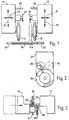
- the illustrated grinding machine has two wheel heads 10, 12 respectively carrying grinding wheels 14, 16 in coaxial relationship for grinding two spaced positions along a workpiece 18 rotatable betwen a headstock 20 and a tailstock 22.
- a rotary drive for each grinding wheel 14, 16 is housed within the respective wheel head, and the infeed/outfeed movement of each grinding wheel is produced by a controlled feed movement of the respective wheel head, as indicated by the arrows 24, 26.
- the wheel heads 10, 12 respectively carry dressing or truing tools 28, 30, herein referred to as dressers.
- the dressers 28, 30, are not coaxial, but disposed on opposite sides of a vertical plane through the axis of the grinding wheels, as will be clear from Figures 2 and 3.
- Each wheel head in addition to its vertical feed movement, is laterally movable towards the other wheel head, as indicated by the arrows 32, 34.
- the dresser 30 can be engaged with the grinding wheel 14 to effect dressing, or likewise for the grinding wheel 16 and dresser 28.
- the two dressers 28, 30 pass one by the other during the lateral feed movement effected in readiness for dressing, and it is possible that each dresser may be vertically aligned with a grinding wheel at the end of this feed movement. However, simultaneous dressing of both grinding wheels is not possible because the respective distances between the centres of the respective pairs of grinding wheels and dressers will not be the same.
- the two dressers 28, 30 are preferably mounted at different distances from the sides of the wheel heads 10, 12 such that when one dresser 28 is truing grinding wheel 16, the other dresser 30 is laterally displaced from, i.e. non-aligned with, its grinding wheel 14.
- the sensing means 36, 38 may be adjustable to allow for the different lateral movements to be carried out when the respective pairs of grinding wheels and dressers are to be aligned.
- the vertical feed movement of one dresser (or grinding wheel) necessary for dressing increases the separation of the other dresser and grinding wheel.
- the dresser 30, 28 traverses across the face of the grinding wheel 14, 16 to dress, or true the wheel.
- the actual grinding and dressing or truing processes carried out by the machine are not herein described, because they are practised in a wholly conventional manner.
- FIG. 4 to 7 A preferred, more versatile machine is illustrated in Figures 4 to 7, wherein the same reference numerals as Figures 1 to 3 are employed for corresponding parts.
- the dressers 28, 30 are mounted on respective slides 40, 42 which are themselves slidably mounted for lateral movement of the dressers on guides 44 (see Figure 7) housed within the respective wheel heads 10, 12.
- References 46, 48 denote driving means for the respective slides 40, 42.
- the machine is shown in the condition for conventional dual grinding of a workpiece by the spaced grinding wheels 14, 16.
- the grinding wheels 14, 16 are shown non-aligned axially.
- these grinding wheels could be of quite substantially different diameters.
- the axes of the dressers 28, 30 again lie in front of and behind the plane of the Figure 4 drawing, as is apparent from the plan view of a wheel head shown in Figure 6, in which reference 50 denotes the axis of the grinding wheel 14, typically a diamond wheel, and reference 52 denotes the axis of the dresser 28, typically a carbonboron wheel.
- Figure 5 shows the machine when in the condition for truing the grinding wheel 16 with the dresser 28.
- Slide 40 has been operated, in conjunction with a relative lateral movement of the wheel heads 14, 16, possibly to an extent controlled by a suitable sensing means (not shown), to bring dresser 28 into alignment with grinding wheel 16. Relative vertical movement of the two wheel heads 14, 16 is being carried out to effect truing.
- FIG 6 also shows, in diagrammatic manner, one possible form of drive means 46, 48 contained within each wheel head 14, 16, for effecting movement of the slide.
- This drive means may be electrically or hydraulically powered, for example.
Landscapes
- Engineering & Computer Science (AREA)
- Mechanical Engineering (AREA)
- Grinding-Machine Dressing And Accessory Apparatuses (AREA)
- Finish Polishing, Edge Sharpening, And Grinding By Specific Grinding Devices (AREA)
- Grinding Of Cylindrical And Plane Surfaces (AREA)
Claims (12)
- Ein Verfahren zum Abziehen oder Abdrehen der Schleifscheiben einer Doppelkopf-Schleifmaschine, gemäß dem die beiden Schleifköpfe (10, 12) zusätzlich zu einer ersten und einer zweiten axial voneinander getrennten Schleifscheibe (14 bzw. 16) eine erste und eine zweite Abdrehvorrichtung (28, 30) tragen, gekennzeichnet durch die Stufe des axialen Bewegens des ersten Schleifkopfes (10) entlang des zweiten Schleifkopfes (12), damit die erste Abdrehvorrichtung (28) zum Abdrehen der zweiten Schleifscheibe (16) befähigt wird.
- Eine Doppelkopf-Schleifmaschine mit einem ersten und einem zweiten Schleifkopf (10, 12), die eine erste bzw. eine zweite Schleifscheibe (14, 16) tragen, wobei der erste bzw. der zweite Schleifkopf auch eine erste und eine zweite Schleifscheibenabdrehvorrichtung (28, 30) trägt und die beiden Schleifköpfe relativ zueinander bewegbar sind, um die erste Abdrehvorrichtung (28) zum Abdrehen der zweiten Schleifscheibe (16) und die zweite Abdrehvorrichtung (30) zum Abdrehen der ersten Schleifscheibe (14) zu befähigen.
- Eine Doppelkopf-Schleifmaschine nach Anspruch 2, wobei die beiden Schleifköpfe (10, 12) beide in zwei Koordinatenrichtungen verschiebbar sind, zuerst in einer seitlichen Bewegung in Richtung aufeinander zu und voneinander weg und zweitens in einer in rechten Winkeln dazu stehenden Vorschubbewegung.
- Eine Doppelkopf-Schleifmaschine nach Anspruch 3, wobei die seitliche Bewegung parallel zu einer durch die erste und die zweite Schleifscheibe (14, 16) durchtretenden Achse und die Vorschubbewegung unter rechten Winkeln zu der Achse liegt und die Hin- und Wegbewegung der jeweiligen Schleifscheibe gegenüber einem Werkstück (18) wie auch die Anlage der jeweiligen Abdrehvorrichtung an einer Schleifscheibe zuläßt.
- Eine Doppelkopf-Schleifmaschine nach Anspruch 4, wobei die Achsen durch die erste und die zweite Schleifscheibe koaxial zueinander sind.
- Eine Doppelkopf-Schleifmaschine nach irgendeinem der Ansprüche 2 bis 5, wobei die erste und die zweite Abdrehvorrichtung in den beiden Schleifköpfen nicht ausgerichtet sind, aber beide in einer Ebene liegen, die zu der Axialebene, die durch die Achse der Schleifscheiben durchtritt, senkrecht steht und die die Bewegungsrichtungen der Schleifköpfe enthält, bzw. auf sich gegenüberliegenden Seiten dieser axialen Ebene liegen, so daß sich die erste Abdrehvorrichtung an der zweiten Abdrehvorrichtung vorbeibewegen kann, wenn die erste Abdrehvorrichtung zum Abdrehen der zweiten Schleifscheibe verwendet wird, und umgekehrt.
- Eine Doppelkopf-Schleifmaschine nach irgendeinem der Ansprüche 2 bis 6, wobei die richtige Kalibrierung der Seitenlage mit Hilfe eines Fühlers auf einem Schleifkopf und eines Tastbolzens auf dem anderen Schleifkopf erreicht wird.
- Eine Doppelkopf-Schleifmaschine nach Anspruch 7, wobei der Fühler und der Tastbolzen dem die Seitenbewegung bewirkenden Antrieb ein Haltesignal zuführen.
- Eine Doppelkopf-Schleifmaschine nach Anspruch 7 oder Anspruch 8, wobei der Fühler zwischen zwei Zuständen verstellbar ist, wenn die Seitenbewegung zum Verbringen der ersten Abdrehvorrichtung in eine Ausrichtung mit der zweiten Schleifscheibe nicht die gleiche ist wie die zum Verbringen der zweiten Abdrehvorrichtung in Ausrichtung mit der ersten Schleifscheibe.
- Eine Doppelkopf-Schleifmaschine nach irgendeinem der Ansprüche 2 bis 9, wobei das Abdrehen durch eine Bewegung nur eines Schleifkopfes bewirkt wird.
- Eine Doppelkopf-Schleifmaschine nach irgendeinem der Ansprüche 2 bis 10 mit einer Lage der Abdrehvorrichtung (28, 30) in einer festen Beziehung zu dem jeweiligen Schleifkopf (10, 12), wobei die gesamte seitliche Relativbewegung zwischen den Schleifköpfen zum Bewirken des Abdrehens von dem Schleifkopf bewirkt wird, der die abzudrehende Schleifscheibe trägt.
- Eine Doppelkopf-Schleifmaschine nach irgendeinem der Ansprüche 2 bis 11, wobei die Abdrehvorrichtungen (28, 30) unabhängig von der Seitenbewegung der die jeweilige Abdrehvorrichtung tragenden Schleifköpfe (10, 12) beide seitlich verschiebbar sind.
Applications Claiming Priority (5)
| Application Number | Priority Date | Filing Date | Title |
|---|---|---|---|
| GB9416795A GB9416795D0 (en) | 1994-08-19 | 1994-08-19 | Improvements in or relating to grinding machines |
| GB9416795 | 1994-08-19 | ||
| GBGB9502812.2A GB9502812D0 (en) | 1995-02-14 | 1995-02-14 | Improvements in or relating to grinding machine |
| GB9502812 | 1995-02-14 | ||
| PCT/GB1995/001446 WO1996005940A1 (en) | 1994-08-19 | 1995-06-20 | Improvements in or relating to grinding machines |
Publications (2)
| Publication Number | Publication Date |
|---|---|
| EP0724501A1 EP0724501A1 (de) | 1996-08-07 |
| EP0724501B1 true EP0724501B1 (de) | 1999-07-07 |
Family
ID=26305482
Family Applications (1)
| Application Number | Title | Priority Date | Filing Date |
|---|---|---|---|
| EP95922620A Expired - Lifetime EP0724501B1 (de) | 1994-08-19 | 1995-06-20 | Verbesserungen an/oder in verband mit schleifmaschinen |
Country Status (5)
| Country | Link |
|---|---|
| EP (1) | EP0724501B1 (de) |
| AU (1) | AU2745195A (de) |
| DE (1) | DE69510651T2 (de) |
| ES (1) | ES2133784T3 (de) |
| WO (1) | WO1996005940A1 (de) |
Families Citing this family (8)
| Publication number | Priority date | Publication date | Assignee | Title |
|---|---|---|---|---|
| US5975995A (en) * | 1997-06-25 | 1999-11-02 | Unova Ip Corp. | Machining apparatus and method |
| DE19940687A1 (de) | 1999-08-27 | 2001-03-01 | Mikrosa Werkzeugmaschinen Gmbh | Schleifmaschinen zum spitzenlosen Schleifen von Werkstücken |
| US6450864B1 (en) | 2000-10-13 | 2002-09-17 | Raphael W. Smith | End mill grinder with two independently adjustable grinding wheels |
| DE10329724C5 (de) * | 2003-07-02 | 2015-11-12 | Niles Werkzeugmaschinen Gmbh | Vorrichtung zum Schleifen von insbesondere Innenprofilen |
| GB2408224B (en) * | 2003-11-21 | 2005-11-09 | Unova Uk Ltd | Improvements in and relating to grinding machines |
| JP6540198B2 (ja) * | 2015-04-28 | 2019-07-10 | 株式会社ジェイテクト | 複合研削盤及び複合研削方法 |
| JP6754272B2 (ja) * | 2016-10-24 | 2020-09-09 | 株式会社ディスコ | 研削装置 |
| CN108789079B (zh) * | 2018-05-31 | 2020-05-12 | 安徽扬子职业技术学院 | 一种翻转式汽车车身打磨设备 |
Family Cites Families (4)
| Publication number | Priority date | Publication date | Assignee | Title |
|---|---|---|---|---|
| CH339530A (fr) * | 1954-09-07 | 1959-06-30 | Gleason Works | Machine à meuler des organes comportant des dents |
| JPS5942268A (ja) * | 1982-08-31 | 1984-03-08 | Toyoda Mach Works Ltd | 砥石修正装置 |
| SE445983B (sv) * | 1984-12-19 | 1986-08-04 | Uva Ab | Med skerpningsverktyg forsedd slipmaskindocka |
| JPH04348869A (ja) * | 1991-03-28 | 1992-12-03 | Toyoda Mach Works Ltd | アンギュラ砥石の修正装置 |
-
1995
- 1995-06-20 EP EP95922620A patent/EP0724501B1/de not_active Expired - Lifetime
- 1995-06-20 DE DE69510651T patent/DE69510651T2/de not_active Expired - Fee Related
- 1995-06-20 ES ES95922620T patent/ES2133784T3/es not_active Expired - Lifetime
- 1995-06-20 AU AU27451/95A patent/AU2745195A/en not_active Abandoned
- 1995-06-20 WO PCT/GB1995/001446 patent/WO1996005940A1/en not_active Ceased
Also Published As
| Publication number | Publication date |
|---|---|
| ES2133784T3 (es) | 1999-09-16 |
| DE69510651D1 (de) | 1999-08-12 |
| AU2745195A (en) | 1996-03-14 |
| DE69510651T2 (de) | 1999-12-02 |
| EP0724501A1 (de) | 1996-08-07 |
| WO1996005940A1 (en) | 1996-02-29 |
Similar Documents
| Publication | Publication Date | Title |
|---|---|---|
| US5443338A (en) | Machine for the precision working of the tooth flanks of gear-shaped workpieces with an internally toothed tool | |
| US8882564B2 (en) | Gear grinding machine and method of dressing a grinding tool | |
| KR100553409B1 (ko) | 공작물의 연삭방법 및 장치 | |
| CA2372659C (en) | Method for grinding convex running surfaces and outside diameters on undulated workpieces in a clamping, and a grinding machine for carrying out the method | |
| US20100304642A1 (en) | Gear Cutting Machine | |
| JPH0899242A (ja) | 複合加工用の工作機械 | |
| EP0724501B1 (de) | Verbesserungen an/oder in verband mit schleifmaschinen | |
| EP1088621A3 (de) | Verfahren und Vorrichtung zum Bearbeiten eines Werkstücks mit mehrere Werkzeugköpfe | |
| US7134936B2 (en) | Grinding head for a grinding machine for glass slabs, and machine equipped with such head | |
| JPH0295556A (ja) | 端面測定装置を備えた研削装置 | |
| JPH10501758A (ja) | 数値制御式旋盤 | |
| GB2292329A (en) | Dressing the grinding wheels of dual head grinding machines | |
| EP0823310A1 (de) | Werkzeugmaschine für kombinierte arbeit | |
| EP1121223B1 (de) | Verfahren und vorrichtung zum schleifen von verbundbauteilen | |
| US5183026A (en) | Method and apparatus for dressing an angular grinding wheel | |
| DE19920467C2 (de) | Schleifmaschine, sowie Verfahren zur Bearbeitung eines Werkstückes in einer Schleifmaschine | |
| US5865667A (en) | Grinding machine | |
| US5885038A (en) | Machine for finishing the tooth flanks of gear-shaped workpieces with an internal gear tool | |
| EP0722810B1 (de) | Federendenschleifmaschine | |
| US5890401A (en) | Apparatus for the continuous path-controlled sharpening of saw toothings | |
| CN119703999A (zh) | 立式复合磨床 | |
| US20060168814A1 (en) | Method and machine tool for machining a tire of a train wheel set | |
| EP0406775A2 (de) | Schleifmaschine | |
| CN101154098A (zh) | 数字控制器及其程序写入方法以及由此控制的切削机 | |
| CN210435848U (zh) | 医用旋转工具加工用六轴磨床 |
Legal Events
| Date | Code | Title | Description |
|---|---|---|---|
| PUAI | Public reference made under article 153(3) epc to a published international application that has entered the european phase |
Free format text: ORIGINAL CODE: 0009012 |
|
| 17P | Request for examination filed |
Effective date: 19960229 |
|
| AK | Designated contracting states |
Kind code of ref document: A1 Designated state(s): DE ES FR IT |
|
| 17Q | First examination report despatched |
Effective date: 19970312 |
|
| GRAG | Despatch of communication of intention to grant |
Free format text: ORIGINAL CODE: EPIDOS AGRA |
|
| GRAG | Despatch of communication of intention to grant |
Free format text: ORIGINAL CODE: EPIDOS AGRA |
|
| GRAH | Despatch of communication of intention to grant a patent |
Free format text: ORIGINAL CODE: EPIDOS IGRA |
|
| ITF | It: translation for a ep patent filed | ||
| GRAG | Despatch of communication of intention to grant |
Free format text: ORIGINAL CODE: EPIDOS AGRA |
|
| DAX | Request for extension of the european patent (deleted) | ||
| GRAG | Despatch of communication of intention to grant |
Free format text: ORIGINAL CODE: EPIDOS AGRA |
|
| GRAH | Despatch of communication of intention to grant a patent |
Free format text: ORIGINAL CODE: EPIDOS IGRA |
|
| RAP1 | Party data changed (applicant data changed or rights of an application transferred) |
Owner name: UNOVA U.K. LIMITED |
|
| GRAH | Despatch of communication of intention to grant a patent |
Free format text: ORIGINAL CODE: EPIDOS IGRA |
|
| ITF | It: translation for a ep patent filed | ||
| GRAA | (expected) grant |
Free format text: ORIGINAL CODE: 0009210 |
|
| AK | Designated contracting states |
Kind code of ref document: B1 Designated state(s): DE ES FR IT |
|
| REF | Corresponds to: |
Ref document number: 69510651 Country of ref document: DE Date of ref document: 19990812 |
|
| ET | Fr: translation filed | ||
| REG | Reference to a national code |
Ref country code: ES Ref legal event code: FG2A Ref document number: 2133784 Country of ref document: ES Kind code of ref document: T3 |
|
| PLBE | No opposition filed within time limit |
Free format text: ORIGINAL CODE: 0009261 |
|
| STAA | Information on the status of an ep patent application or granted ep patent |
Free format text: STATUS: NO OPPOSITION FILED WITHIN TIME LIMIT |
|
| 26N | No opposition filed | ||
| PGFP | Annual fee paid to national office [announced via postgrant information from national office to epo] |
Ref country code: FR Payment date: 20050617 Year of fee payment: 11 |
|
| PGFP | Annual fee paid to national office [announced via postgrant information from national office to epo] |
Ref country code: ES Payment date: 20050708 Year of fee payment: 11 |
|
| PGFP | Annual fee paid to national office [announced via postgrant information from national office to epo] |
Ref country code: DE Payment date: 20050801 Year of fee payment: 11 |
|
| PG25 | Lapsed in a contracting state [announced via postgrant information from national office to epo] |
Ref country code: ES Free format text: LAPSE BECAUSE OF NON-PAYMENT OF DUE FEES Effective date: 20060621 |
|
| PGFP | Annual fee paid to national office [announced via postgrant information from national office to epo] |
Ref country code: IT Payment date: 20060630 Year of fee payment: 12 |
|
| PG25 | Lapsed in a contracting state [announced via postgrant information from national office to epo] |
Ref country code: DE Free format text: LAPSE BECAUSE OF NON-PAYMENT OF DUE FEES Effective date: 20070103 |
|
| REG | Reference to a national code |
Ref country code: FR Ref legal event code: ST Effective date: 20070228 |
|
| REG | Reference to a national code |
Ref country code: ES Ref legal event code: FD2A Effective date: 20060621 |
|
| PG25 | Lapsed in a contracting state [announced via postgrant information from national office to epo] |
Ref country code: FR Free format text: LAPSE BECAUSE OF NON-PAYMENT OF DUE FEES Effective date: 20060630 |
|
| PG25 | Lapsed in a contracting state [announced via postgrant information from national office to epo] |
Ref country code: IT Free format text: LAPSE BECAUSE OF NON-PAYMENT OF DUE FEES Effective date: 20070620 |