EP0724476B1 - Methode und vorrichtung zur abgasreinigung - Google Patents
Methode und vorrichtung zur abgasreinigung Download PDFInfo
- Publication number
- EP0724476B1 EP0724476B1 EP94922410A EP94922410A EP0724476B1 EP 0724476 B1 EP0724476 B1 EP 0724476B1 EP 94922410 A EP94922410 A EP 94922410A EP 94922410 A EP94922410 A EP 94922410A EP 0724476 B1 EP0724476 B1 EP 0724476B1
- Authority
- EP
- European Patent Office
- Prior art keywords
- gases
- flue
- liquid
- container
- flue gas
- Prior art date
- Legal status (The legal status is an assumption and is not a legal conclusion. Google has not performed a legal analysis and makes no representation as to the accuracy of the status listed.)
- Expired - Lifetime
Links
Images

Classifications
-
- B—PERFORMING OPERATIONS; TRANSPORTING
- B01—PHYSICAL OR CHEMICAL PROCESSES OR APPARATUS IN GENERAL
- B01D—SEPARATION
- B01D47/00—Separating dispersed particles from gases, air or vapours by liquid as separating agent
- B01D47/02—Separating dispersed particles from gases, air or vapours by liquid as separating agent by passing the gas or air or vapour over or through a liquid bath
- B01D47/021—Separating dispersed particles from gases, air or vapours by liquid as separating agent by passing the gas or air or vapour over or through a liquid bath by bubbling the gas through a liquid bath
-
- B—PERFORMING OPERATIONS; TRANSPORTING
- B01—PHYSICAL OR CHEMICAL PROCESSES OR APPARATUS IN GENERAL
- B01D—SEPARATION
- B01D47/00—Separating dispersed particles from gases, air or vapours by liquid as separating agent
- B01D47/02—Separating dispersed particles from gases, air or vapours by liquid as separating agent by passing the gas or air or vapour over or through a liquid bath
- B01D47/024—Separating dispersed particles from gases, air or vapours by liquid as separating agent by passing the gas or air or vapour over or through a liquid bath by impinging the gas to be cleaned essentially in a perpendicular direction onto the liquid surface
-
- B—PERFORMING OPERATIONS; TRANSPORTING
- B01—PHYSICAL OR CHEMICAL PROCESSES OR APPARATUS IN GENERAL
- B01D—SEPARATION
- B01D53/00—Separation of gases or vapours; Recovering vapours of volatile solvents from gases; Chemical or biological purification of waste gases, e.g. engine exhaust gases, smoke, fumes, flue gases, aerosols
- B01D53/14—Separation of gases or vapours; Recovering vapours of volatile solvents from gases; Chemical or biological purification of waste gases, e.g. engine exhaust gases, smoke, fumes, flue gases, aerosols by absorption
- B01D53/18—Absorbing units; Liquid distributors therefor
-
- B—PERFORMING OPERATIONS; TRANSPORTING
- B01—PHYSICAL OR CHEMICAL PROCESSES OR APPARATUS IN GENERAL
- B01D—SEPARATION
- B01D53/00—Separation of gases or vapours; Recovering vapours of volatile solvents from gases; Chemical or biological purification of waste gases, e.g. engine exhaust gases, smoke, fumes, flue gases, aerosols
- B01D53/34—Chemical or biological purification of waste gases
- B01D53/46—Removing components of defined structure
- B01D53/64—Heavy metals or compounds thereof, e.g. mercury
-
- B—PERFORMING OPERATIONS; TRANSPORTING
- B01—PHYSICAL OR CHEMICAL PROCESSES OR APPARATUS IN GENERAL
- B01D—SEPARATION
- B01D53/00—Separation of gases or vapours; Recovering vapours of volatile solvents from gases; Chemical or biological purification of waste gases, e.g. engine exhaust gases, smoke, fumes, flue gases, aerosols
- B01D53/34—Chemical or biological purification of waste gases
- B01D53/74—General processes for purification of waste gases; Apparatus or devices specially adapted therefor
-
- F—MECHANICAL ENGINEERING; LIGHTING; HEATING; WEAPONS; BLASTING
- F23—COMBUSTION APPARATUS; COMBUSTION PROCESSES
- F23J—REMOVAL OR TREATMENT OF COMBUSTION PRODUCTS OR COMBUSTION RESIDUES; FLUES
- F23J15/00—Arrangements of devices for treating smoke or fumes
- F23J15/02—Arrangements of devices for treating smoke or fumes of purifiers, e.g. for removing noxious material
- F23J15/04—Arrangements of devices for treating smoke or fumes of purifiers, e.g. for removing noxious material using washing fluids
Definitions
- the present invention relates to a gas purifier, and more particularly, but not exclusively, to the cleansing or purifying of flue-gases with the aid of a flue-gas purifier, whereby the efficiency of the combustion system is improved and the use of a conventional smoke stack is rendered unnecessary.
- the object of the present invention is to overcome the aforesaid problems. This object is achieved with a method and a flue-gas purifier according to the following claims, which also disclose the individual characteristic features of the invention.
- DE-A-1 266 730 From DE-A-1 266 730 is known an apparatus for cleaning gases generated in a combustion process, including a fan operative to draw the gases through the liquid of a partially filled first container in a suction phase, followed by a pressure phase where the gases are forced through the liquid of a separate, partially filled second container before the gases are discharged.
- the apparatus of DE-A-1 266 730 does however not provide for a turbulent gas flow outside the liquids.
- US-A-3 998 613 discloses a flue gas cleaning apparatus having a multiplicity of successive, individual and communicating chambers partially filled with liquid. Powerful pump means are arranged to cause liquid displacement from one chamber to the next, and to force the gas through the liquid from the inlet side to the outlet side, passing from one chamber to the other through openings disposed beneath the liquid level. No means are provided for a turbulent gas flow outside the liquid and an increased surface contact between flue gas and liquid.
- AT-A-371 235 is also mentioned as it discloses a device for utilizing the heat of the flue gases from a combustion process by forcing the gases through a number of individual containers, partially filled with liquid, and leading a heat exchange medium in close contact with the container sides.
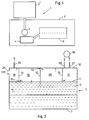
- Fig. 1 illustrates a heating plant 1 which includes an inventive flue-gas purifier.
- the plant 1 is housed in a container 2 and includes a combustion furnace 3, a boiler 4 in which heat exchange with the heat-carrying medium takes place, and an inventive flue-gas purifier 5.
- Fuel for combustion, for instance wood chips or oil, is taken from a fuel store 6' located outside the container 2, and charged to the furnace 3.
- the described arrangement in which the invention is applied with a plant or system in which the major part thereof is housed in a container has no significance with regard to the invention, since the invention can be applied with practically any type of combustion plant.
- the heat exchange effected in the boiler 4 is adapted so that the temperature of the flue-gases leaving the boiler will be maintained at about 100°C. Normally, this temperature is not sufficient to discharge the flue-gases as effectively as is necessary. However, a temperature of 100°C is clearly sufficient to prevent damage to the boiler 4 and also to the flue-gas conduits leading from the boiler to the flue-gas purifier 5.
- the inventive flue-gas purifier 5 includes a box-like container 6 which is made of welded steel sheet for instance, and has a rectangular shape when seen from above.
- the container bottom 7 has a V-shaped cross-section and accomadates an outfeed screw (not shown) in the apex 8 thereof.
- a partition wall 9 extends downwardly from the lid or cover 10 of the container 6 along the length of the container from end-wall to end-wall in a direction towards the container bottom 7, where it terminates at a distance of roughly one-third of the vertical distance from the apex 8 of the V-shaped bottom 7.
- This partition wall 9 may be insulated.
- the container 6 is filled partially with water to a level 11, which lies roughly at two-thirds of the container height above the apex 8 of the bottom 7.
- level sensors and water-filling and water-draining devices may be provided for the purpose of maintaining a desired volume of water in the container 6.
- a wall or baffle 12 extends transversely across the container 6 from a location approximately midway of the length of the container. This wall 12 defines a gap 13 between its upper edge and the container cover 10 and extends downwardly to terminate at a short distance beneath the water surface 11.
- Another wall or baffle 14 extends transversely across the container 6, between the wall 12 and the end-wall of the container 6, this end-wall including a flue-gas inlet 25.
- the wall 14 is attached to the container cover 10 and extends down towards the water level 11, but terminates short of the water level so as to form a gap 15.
- a further wall or baffle 16 is provided between the partition wall 9 and one long wall 17 of the container 6.
- the walls 12, 14 and 16 form a series of chambers 18-24 above the water level 11.
- the bottom end-edges of the walls 12, 14, 16 will preferably be slotted so as to have a comb-like configuration which functions to divide the flue-gases into many smaller flows, so that the flue-gases which pass through the chambers 18-24 and partially through the water will be divided into the smallest possible flow units for the best possible contact with the water.
- the partition wall 9 divides the container 6 into two longitudinally extending parts or compartments A and B above the water level 11.
- the one part A includes sequentially the chambers 18-21, wherein the flue-gas inlet 25 which receives flue-gases from the boiler 4 discharges into the chamber 18.
- the chambers 18-21 forming the part A thus lie sequentially between one long side 17 of the container 6 and the partition wall 9.
- the inlet 27 of an air pump 26, for instance a fan is connected to the chamber 21 and located in the container cover 10, while the fan outlet 28 is located in the chamber 22 which lies opposite the chambers 20 and 21 but between the partition wall and the opposite container long wall.
- the chamber 24 lies opposite the chamber 18 between the partition wall 9 and the opposing long wall, while the chamber 23 lies between these chambers 22 and 24 centrally opposite the chamber 19.
- the chambers 22, 23 and 24 thus form the part B of the container 6.
- the fan outlet 28 opens out beneath the water level 11, suitably into a spray nozzle (not shown), which functions to spread the flue-gases throughout the water.
- An outlet 29 for purified and cooled gases is provided in the chamber 24, which is the last chamber in the series.
- the fan 26 is controlled by the pressure in the boiler 4 and in the part A of the container 6 by means of electronic control equipment not shown. In order to achieve proper combustion, there is preferably maintained in the boiler 4 a subpressure of about 50 Pa (5 mm water column), which can normally be achieved by causing the fan 26 to maintain a subpressure of about 100 Pa (10 mm water column) in part A of the container 6. Naturally, different factors influence the pressure primarily in the boiler 4, although the fan 26 can be controlled readily to maintain the boiler pressure at a desired level with the aid of proper control equipment, wherein the pressure in the container part A will be held at an acceptable level in response to this control. It is essential that the pressure in the boiler 4 is correct for the combustion process, whereas the pressure in the container part A is less essential but will constantly lie somewhat beneath the boiler pressure, since the fan 26 primarily evacuates the container part A and secondarily the boiler 4.
- the flue-gases sucked from the boiler 4 into the chamber 18 of the flue-gas purifier 5 have a temperature of about 100°C.
- the flue-gases continue from the chamber 18 through the gap 15 between the wall 14 and the water surface 11 and are divided into part-flows by virtue of the comb-like lower part of the wall 14, and impinge also on the water surface.
- the flue-gases swirl around in the chamber 19 and continue in the direction of the arrow through the gap 13 defined between the container cover 10 and the upper edge of the wall 12 into the chamber 20, in which the flue-gases continue to swirl and from which the gases pass out through the gap between the water surface 11 and the wall 16 and into the chamber 21, as indicated by the arrow.
- the flue-gases will impinge on the surface of the water 11 during the whole of their transportation through the chambers in the container part A.
- the flue-gases are sucked from the chamber 21 into the fan 26 through the inlet 27, and then pass out from the fan through the outlet 28 and into the chamber 22 in part B of the container 6.
- the outlet 28 opens into a nozzle which is lowered into the water to a level between the bottom edge of the partition wall 9 and the water surface 11.
- the flue-gases are then urged through the chambers 23 and 24 in similar routes or while moving in similar patterns as the flue-gases in the chambers in the container part A, and finally reach the outlet 29 through which they are discharged to atmosphere.
- the flue-gases are divided into small bubbles, the more the better, which come into contact with the water in the container 6.
- the flue-gases are therewith cooled and particles of soot and other contaminants carried by the gases will precipitate into the water.
- the flue-gases contain 40% steam, 15% carbon dioxide and 35% nitrogen gas when entering the container 6.
- the gases will contain between 6 and 15% carbon dioxide, this value varying in dependence on the pH of the water, and 35% nitrogen.
- the steam is condensed in the container 6, due to the fact that container water is kept at a temperature beneath 100°C, the nitrogen gas is inert and natural and can therefore be discharged to atmosphere to no detriment, while the carbon dioxide emission lies within fully acceptable values.
- the container may include a heat exchanger which functions to cool the water and also to enable further heat to be recovered in addition to that covered by the boiler 4.
- the container water will preferably be maintained at a pH above 7, in order to bind heavy metals in the flue-gases. This may be achieved with the aid of a device (not shown) which functions to deliver lime to the water, wherein the volumes in which the lime is dispensed may be controlled by a conventional detector or sensor means which monitors the pH of the water with respect to a preset pH value.
- the invention is based on the concept of causing the flue-gases to pass through a container which has two departments A and B which are mutually separated with regard to the subpressures and overpressures in the routes followed by the flue-gases through the container 6, but which are mutually joined with regard to the water volume in the container 6, and by drawing flue-gases by suction into one department or part A and transferring the flue-gases from this container part into the second container part or department B under pressure.
- the flue-gases are finely divided as they pass through the comb-like bottom edges of the walls 12, 14, 16 and are released into the container part or department B through a spray nozzle.
- the described and illustrated embodiment of the flue-gas purifier is only one of several possible embodiments.
- the container parts A and B may well be arranged in some other sequence, for instance one after the other, in a circle, etc., and that the container parts may include more or fewer chambers without departing from the inventive concept as defined in the following claims.
Landscapes
- Chemical & Material Sciences (AREA)
- Engineering & Computer Science (AREA)
- Chemical Kinetics & Catalysis (AREA)
- Environmental & Geological Engineering (AREA)
- General Chemical & Material Sciences (AREA)
- Oil, Petroleum & Natural Gas (AREA)
- Analytical Chemistry (AREA)
- Health & Medical Sciences (AREA)
- Biomedical Technology (AREA)
- Mechanical Engineering (AREA)
- General Engineering & Computer Science (AREA)
- Treating Waste Gases (AREA)
- Exhaust Gas After Treatment (AREA)
- Gas Separation By Absorption (AREA)
- Chimneys And Flues (AREA)
- Separation Of Particles Using Liquids (AREA)
Claims (9)
- Verfahren zur Reinigung von Abgasen, die bei einem Verbrennungsprozeß entstehen, wobei die Abgase vor dem Entweichen in die Umgebung zuerst einer Saugphase unterworfen werden, der eine Druckphase folgt, bei welcher die Gase mit einem innerhalb eine Behälters befindlichen gemeinsamen Volumens in Kontakt gebracht bzw. durch dieses hindurchgeführt werden,
dadurch gekennzeichnet, daß die Gase während der Saugphase über eine Anzahl von Kanten, die kammförmig ausgebildet sind, gefährt werden, so daß sie in eine Mehrzahl von Strömungseinheiten unterteilt werden, und daß die Gase oberhalb und in engem Oberflächenkontakt mit der Flüssigkeit gebracht werden, wenn sie durch die Kanten strömen, und daß die Gase während der Druckphase durch die Flüssigkeit und über eine Anzahl ähnlich geformter Kanten oberhalb des Flüssigkeitsspiegels gedrückt werden, wobei die Saug- und Druckphasen voneinander getrennt und teilweise durch den Oberflächenpegel des gemeinsamen Flüssigkeitsvolumens definiert werden. - Verfahren nach Anspruch 1,
dadurch gekennzeichnet, daß in dem Behälter eine Mehrzahl aufeinanderfolgender Kammern angeordnet sind, die durch Wände getrennt sind, wobei die unteren Enden der Wände mit kammförmigen Kanten ausgebildet und so angeordnet sind, daß die Abgase in engem Kontakt mit der Flüssigkeit gebracht werden, wenn sie von einer Kammer in die nächste gelangen, und als Option sowohl in der Saug- wie auch der Druckphase teilweise durch die Flüssigkeit gelangen. - Verfahren nach Anspruch 1,
dadurch gekennzeichnet, daß die Saugphase von der Druckphase durch eine Trennwand getrennt ist, die vom Behälterdeckel in die Flüssigkeit bis gut unter deren Spiegel reicht, und daß die Abgase durch eine Pumpe von der Saugseite in die Druckseite gezogen werden, welche die Gase auf der Druckseite durch die Flüssigkeit befördert, wobei die Gase durch eine eingetauchte Düse in die Flüssigkeit eingeblasen werden. - Verfahren nach Anspruch 3,
dadurch gekennzeichnet, daß der Pumpenbetrieb so gesteuert wird, daß ein vorbestimmter Unterdruck für den Verbrennungsprozeß aufrechterhalten wird, aus dem die zu reinigenden Abgase durch die Pumpe abgesaugt werden. - Verfahren nach Anspruch 1,
dadurch gekennzeichnet, daß die Temperatur der Abgase auf etwa 100°C abgesenkt wird, ehe die Gase das Flüssigkeitsvolumen erreichen, und daß die Flüssigkeit Wasser ist. - Abgasreiniger (5) zum Reinigen von aus einem Verbrennungsprozeß (3, 4) stammenden Abgasen mit einem geschlossenen Behälter (6), der bis zu einem Pegel (11) mit Flüssigkeit gefüllt ist und einen V-förmigen Boden (8), Längsseiten (17), Endwände und eine Abdeckung (10) hat, ferner einen Abgaseinlaß (25) und einen Abgasauslaß (29) sowie eine Pumpe (26), welche das Abgas während der Reinigung durch den Abgasreiniger drückt,
dadurch gekennzeichnet, daß eine Längstrennwand (9) vertikal von der Abdeckung (10) in die Flüssigkeit ragt und den Behälterraum in eine Saugseite bzw. eine Druckseite unterteilt, daß der Einlaß (25) an der Saugseite und der Auslaß (29) an der Druckseite angebracht sind und die Pumpe (26) so angeordnet ist, daß sie das Abgas von der Saugseite ansaugt und das Gas durch die Flüssigkeit auf der Druckseite drückt, indem sie es durch eine eingetauchte Düse ausbläst, daß sowohl die Saugseite wie auch die Druckseite in eine Mehrzahl aufeinanderfolgender Kammern (18, 24) unterteilt ist, die durch Wände (14, 12, 16) voneinander getrennt sind, daß die Wände abwechselnd quer von der Behälterabdeckung wegragen und dicht oberhalb des Flüssigkeitspegels (11) enden und abwechselnd quer von einem Abstand unter der Behälteroberseite bis unter den Flüssigkeitspegel ragen, wo sie enden, und daß die unteren freien Kanten der Wände (14, 12, 16) kammförmig ausgebildet sind. - Abgasreiniger nach Anspruch 6,
gekennzeichnet durch eine längs verlaufende Bodenschnecke zur Entfernung von Verunreinigungen, die sich aus den Abgasen in die Flüssigkeit niedergeschlagen haben, aus dem Container. - Abgasreinger nach Anspruch 6,
gekennzeichnet durch eine Überwachungseinrichtung für den pH-Wert der Flüssigkeit und Zuführung eines Agens, welches den pH-Wert der Flüssigkeit über 7 hält, zu der Flüssigkeit. - Verwendung des Abgasreinigers nach Anspruch 6 in einer Heizanlage mit einem Brennstoffspeicher, einem Ofen, einem Boiler und dem Abgasreiniger, wobei Ofen, Boiler und Reiniger alle in einem gemeinsamen Gehäuse untergebracht sind.
Applications Claiming Priority (3)
| Application Number | Priority Date | Filing Date | Title |
|---|---|---|---|
| SE9302567A SE503092C2 (sv) | 1993-08-05 | 1993-08-05 | Förfarande och anordning för rening av rökgaser från en förbränningsanläggning |
| SE9302567 | 1993-08-05 | ||
| PCT/SE1994/000720 WO1995004589A1 (en) | 1993-08-05 | 1994-08-01 | Method of flue gas purification and flue gas purifier |
Publications (2)
| Publication Number | Publication Date |
|---|---|
| EP0724476A1 EP0724476A1 (de) | 1996-08-07 |
| EP0724476B1 true EP0724476B1 (de) | 1998-12-09 |
Family
ID=20390734
Family Applications (1)
| Application Number | Title | Priority Date | Filing Date |
|---|---|---|---|
| EP94922410A Expired - Lifetime EP0724476B1 (de) | 1993-08-05 | 1994-08-01 | Methode und vorrichtung zur abgasreinigung |
Country Status (6)
| Country | Link |
|---|---|
| EP (1) | EP0724476B1 (de) |
| AT (1) | ATE174231T1 (de) |
| AU (1) | AU7352894A (de) |
| DE (1) | DE69415172T2 (de) |
| SE (1) | SE503092C2 (de) |
| WO (1) | WO1995004589A1 (de) |
Families Citing this family (2)
| Publication number | Priority date | Publication date | Assignee | Title |
|---|---|---|---|---|
| AU665726B1 (en) * | 1994-08-22 | 1996-01-11 | Ewing, Sarah Frances | Fluid air cleaning apparatus |
| SE511332C2 (sv) * | 1995-07-06 | 1999-09-13 | Masarna I Mora Ab Mimab | Rökgasrenare |
Family Cites Families (3)
| Publication number | Priority date | Publication date | Assignee | Title |
|---|---|---|---|---|
| US3414248A (en) * | 1964-06-27 | 1968-12-03 | Iwanaga Mitsuji | Apparatus for purifying contaminated gases |
| US3998613A (en) * | 1974-10-29 | 1976-12-21 | Attig Donald B | Apparatus for removing sulfur dioxide and particulate matter from flue gases |
| AT371235B (de) * | 1981-01-15 | 1983-06-10 | Stranzinger Hermann | Verfahren und vorrichtung zur ausnutzung der abgaswaerme einer feuerungsanlage |
-
1993
- 1993-08-05 SE SE9302567A patent/SE503092C2/sv not_active IP Right Cessation
-
1994
- 1994-08-01 AU AU73528/94A patent/AU7352894A/en not_active Abandoned
- 1994-08-01 AT AT94922410T patent/ATE174231T1/de not_active IP Right Cessation
- 1994-08-01 EP EP94922410A patent/EP0724476B1/de not_active Expired - Lifetime
- 1994-08-01 DE DE69415172T patent/DE69415172T2/de not_active Expired - Fee Related
- 1994-08-01 WO PCT/SE1994/000720 patent/WO1995004589A1/en not_active Ceased
Also Published As
| Publication number | Publication date |
|---|---|
| DE69415172T2 (de) | 1999-06-24 |
| ATE174231T1 (de) | 1998-12-15 |
| WO1995004589A1 (en) | 1995-02-16 |
| DE69415172D1 (de) | 1999-01-21 |
| SE9302567L (sv) | 1995-02-06 |
| EP0724476A1 (de) | 1996-08-07 |
| AU7352894A (en) | 1995-02-28 |
| SE503092C2 (sv) | 1996-03-25 |
| SE9302567D0 (sv) | 1993-08-05 |
Similar Documents
| Publication | Publication Date | Title |
|---|---|---|
| US3971642A (en) | Gas scrubber | |
| WO1989000661A1 (fr) | Dispositif regulateur de combustion pour chaudieres a lit fluidise | |
| CA2229671C (en) | Direct contact water heater with dual water heating chambers | |
| EP0724476B1 (de) | Methode und vorrichtung zur abgasreinigung | |
| KR20200020348A (ko) | 습식냉각 가스정화장치 | |
| CN210584298U (zh) | 一种烟气控白系统 | |
| US3726064A (en) | Scrubbing apparatus for polluted gases | |
| JPH11148335A (ja) | 湿式排ガス浄化装置 | |
| EP0752264B1 (de) | Rauchgasreiniger | |
| US20240397675A1 (en) | Heat transfer assembly and power electronics device | |
| US2830673A (en) | Smoke-arresting apparatus | |
| KR102124612B1 (ko) | 공기정화 시스템 | |
| CN223988277U (zh) | 湿法除尘装置 | |
| GB1585373A (en) | Method and device for scarfing a workpiece surface to remove defects | |
| SU919715A1 (ru) | Устройство дл очистки газа | |
| RU2097113C1 (ru) | Устройство для очистки газа | |
| RU2175101C1 (ru) | Система утилизации теплоты и очистки выбросных газов | |
| JP2739439B2 (ja) | 湿式脱硫装置 | |
| SU1097357A1 (ru) | Аппарат с подвижной насадкой | |
| SU1474431A1 (ru) | Теплоутилизатор | |
| SU775591A1 (ru) | Способ обработки запыленного газа | |
| RU2042905C1 (ru) | Градирня | |
| CN114146511A (zh) | 一种co炉温降降尘撬块化装置及其操作步骤 | |
| SU957939A1 (ru) | Зернистый фильтр | |
| WO1994008697A1 (en) | Method for flue-gas cleaning |
Legal Events
| Date | Code | Title | Description |
|---|---|---|---|
| PUAI | Public reference made under article 153(3) epc to a published international application that has entered the european phase |
Free format text: ORIGINAL CODE: 0009012 |
|
| 17P | Request for examination filed |
Effective date: 19960131 |
|
| AK | Designated contracting states |
Kind code of ref document: A1 Designated state(s): AT BE DE FR GB SE |
|
| 17Q | First examination report despatched |
Effective date: 19961204 |
|
| GRAG | Despatch of communication of intention to grant |
Free format text: ORIGINAL CODE: EPIDOS AGRA |
|
| GRAG | Despatch of communication of intention to grant |
Free format text: ORIGINAL CODE: EPIDOS AGRA |
|
| GRAH | Despatch of communication of intention to grant a patent |
Free format text: ORIGINAL CODE: EPIDOS IGRA |
|
| GRAH | Despatch of communication of intention to grant a patent |
Free format text: ORIGINAL CODE: EPIDOS IGRA |
|
| GRAA | (expected) grant |
Free format text: ORIGINAL CODE: 0009210 |
|
| AK | Designated contracting states |
Kind code of ref document: B1 Designated state(s): AT BE DE FR GB SE |
|
| REF | Corresponds to: |
Ref document number: 174231 Country of ref document: AT Date of ref document: 19981215 Kind code of ref document: T |
|
| REF | Corresponds to: |
Ref document number: 69415172 Country of ref document: DE Date of ref document: 19990121 |
|
| PG25 | Lapsed in a contracting state [announced via postgrant information from national office to epo] |
Ref country code: SE Free format text: LAPSE BECAUSE OF FAILURE TO SUBMIT A TRANSLATION OF THE DESCRIPTION OR TO PAY THE FEE WITHIN THE PRESCRIBED TIME-LIMIT Effective date: 19990309 |
|
| ET | Fr: translation filed | ||
| PLBE | No opposition filed within time limit |
Free format text: ORIGINAL CODE: 0009261 |
|
| 26N | No opposition filed | ||
| REG | Reference to a national code |
Ref country code: GB Ref legal event code: IF02 |
|
| REG | Reference to a national code |
Ref country code: GB Ref legal event code: 732E |
|
| REG | Reference to a national code |
Ref country code: FR Ref legal event code: TP |
|
| BECA | Be: change of holder's address |
Free format text: 20020523 *SYDKRAFT M?LARV?RME A.B.:BOX 1422, S-701 14 ?REBRO |
|
| PGFP | Annual fee paid to national office [announced via postgrant information from national office to epo] |
Ref country code: GB Payment date: 20030721 Year of fee payment: 10 |
|
| PGFP | Annual fee paid to national office [announced via postgrant information from national office to epo] |
Ref country code: AT Payment date: 20030819 Year of fee payment: 10 |
|
| PGFP | Annual fee paid to national office [announced via postgrant information from national office to epo] |
Ref country code: BE Payment date: 20030825 Year of fee payment: 10 |
|
| PGFP | Annual fee paid to national office [announced via postgrant information from national office to epo] |
Ref country code: DE Payment date: 20030826 Year of fee payment: 10 |
|
| PGFP | Annual fee paid to national office [announced via postgrant information from national office to epo] |
Ref country code: FR Payment date: 20040730 Year of fee payment: 11 |
|
| PG25 | Lapsed in a contracting state [announced via postgrant information from national office to epo] |
Ref country code: GB Free format text: LAPSE BECAUSE OF NON-PAYMENT OF DUE FEES Effective date: 20040801 Ref country code: AT Free format text: LAPSE BECAUSE OF NON-PAYMENT OF DUE FEES Effective date: 20040801 |
|
| PG25 | Lapsed in a contracting state [announced via postgrant information from national office to epo] |
Ref country code: BE Free format text: LAPSE BECAUSE OF NON-PAYMENT OF DUE FEES Effective date: 20040831 |
|
| BERE | Be: lapsed |
Owner name: *SYDKRAFT M?LARV?RME A.B. Effective date: 20040831 |
|
| PG25 | Lapsed in a contracting state [announced via postgrant information from national office to epo] |
Ref country code: DE Free format text: LAPSE BECAUSE OF NON-PAYMENT OF DUE FEES Effective date: 20050301 |
|
| GBPC | Gb: european patent ceased through non-payment of renewal fee |
Effective date: 20040801 |
|
| PG25 | Lapsed in a contracting state [announced via postgrant information from national office to epo] |
Ref country code: FR Free format text: LAPSE BECAUSE OF NON-PAYMENT OF DUE FEES Effective date: 20060428 |
|
| REG | Reference to a national code |
Ref country code: FR Ref legal event code: ST Effective date: 20060428 |
|
| BERE | Be: lapsed |
Owner name: *SYDKRAFT M?LARV?RME A.B. Effective date: 20040831 |