EP0724092B1 - Zweimassenschwungrad mit motorseitig angeordneter Druckplatte - Google Patents
Zweimassenschwungrad mit motorseitig angeordneter Druckplatte Download PDFInfo
- Publication number
- EP0724092B1 EP0724092B1 EP95118411A EP95118411A EP0724092B1 EP 0724092 B1 EP0724092 B1 EP 0724092B1 EP 95118411 A EP95118411 A EP 95118411A EP 95118411 A EP95118411 A EP 95118411A EP 0724092 B1 EP0724092 B1 EP 0724092B1
- Authority
- EP
- European Patent Office
- Prior art keywords
- flywheel
- mass
- dual
- plate
- pressure plate
- Prior art date
- Legal status (The legal status is an assumption and is not a legal conclusion. Google has not performed a legal analysis and makes no representation as to the accuracy of the status listed.)
- Expired - Lifetime
Links
- 238000005299 abrasion Methods 0.000 claims description 18
- 239000000969 carrier Substances 0.000 claims description 6
- 230000000694 effects Effects 0.000 claims description 6
- 238000013016 damping Methods 0.000 claims description 5
- 239000004519 grease Substances 0.000 claims description 5
- 230000000149 penetrating effect Effects 0.000 claims description 2
- 230000009977 dual effect Effects 0.000 description 22
- 230000033001 locomotion Effects 0.000 description 12
- 230000005540 biological transmission Effects 0.000 description 10
- 230000002093 peripheral effect Effects 0.000 description 4
- 238000007789 sealing Methods 0.000 description 4
- 230000009471 action Effects 0.000 description 3
- 230000007704 transition Effects 0.000 description 3
- 230000008901 benefit Effects 0.000 description 2
- 230000015572 biosynthetic process Effects 0.000 description 2
- 210000002105 tongue Anatomy 0.000 description 2
- 239000003082 abrasive agent Substances 0.000 description 1
- 230000004308 accommodation Effects 0.000 description 1
- 238000005452 bending Methods 0.000 description 1
- 238000004891 communication Methods 0.000 description 1
- 238000010276 construction Methods 0.000 description 1
- 230000001419 dependent effect Effects 0.000 description 1
- 238000001914 filtration Methods 0.000 description 1
- 230000006870 function Effects 0.000 description 1
- 230000012447 hatching Effects 0.000 description 1
- 230000000977 initiatory effect Effects 0.000 description 1
- 238000002955 isolation Methods 0.000 description 1
- 230000007246 mechanism Effects 0.000 description 1
- 239000012528 membrane Substances 0.000 description 1
- 238000000465 moulding Methods 0.000 description 1
- 239000002245 particle Substances 0.000 description 1
- 230000035515 penetration Effects 0.000 description 1
- 238000007639 printing Methods 0.000 description 1
- 125000006850 spacer group Chemical group 0.000 description 1
- 239000007858 starting material Substances 0.000 description 1
Images



Classifications
-
- F—MECHANICAL ENGINEERING; LIGHTING; HEATING; WEAPONS; BLASTING
- F16—ENGINEERING ELEMENTS AND UNITS; GENERAL MEASURES FOR PRODUCING AND MAINTAINING EFFECTIVE FUNCTIONING OF MACHINES OR INSTALLATIONS; THERMAL INSULATION IN GENERAL
- F16F—SPRINGS; SHOCK-ABSORBERS; MEANS FOR DAMPING VIBRATION
- F16F15/00—Suppression of vibrations in systems; Means or arrangements for avoiding or reducing out-of-balance forces, e.g. due to motion
- F16F15/10—Suppression of vibrations in rotating systems by making use of members moving with the system
- F16F15/12—Suppression of vibrations in rotating systems by making use of members moving with the system using elastic members or friction-damping members, e.g. between a rotating shaft and a gyratory mass mounted thereon
- F16F15/131—Suppression of vibrations in rotating systems by making use of members moving with the system using elastic members or friction-damping members, e.g. between a rotating shaft and a gyratory mass mounted thereon the rotating system comprising two or more gyratory masses
-
- F—MECHANICAL ENGINEERING; LIGHTING; HEATING; WEAPONS; BLASTING
- F16—ENGINEERING ELEMENTS AND UNITS; GENERAL MEASURES FOR PRODUCING AND MAINTAINING EFFECTIVE FUNCTIONING OF MACHINES OR INSTALLATIONS; THERMAL INSULATION IN GENERAL
- F16D—COUPLINGS FOR TRANSMITTING ROTATION; CLUTCHES; BRAKES
- F16D13/00—Friction clutches
- F16D13/58—Details
- F16D13/70—Pressure members, e.g. pressure plates, for clutch-plates or lamellae; Guiding arrangements for pressure members
- F16D2013/703—Pressure members, e.g. pressure plates, for clutch-plates or lamellae; Guiding arrangements for pressure members the pressure plate on the flywheel side is combined with a damper
-
- F—MECHANICAL ENGINEERING; LIGHTING; HEATING; WEAPONS; BLASTING
- F16—ENGINEERING ELEMENTS AND UNITS; GENERAL MEASURES FOR PRODUCING AND MAINTAINING EFFECTIVE FUNCTIONING OF MACHINES OR INSTALLATIONS; THERMAL INSULATION IN GENERAL
- F16D—COUPLINGS FOR TRANSMITTING ROTATION; CLUTCHES; BRAKES
- F16D13/00—Friction clutches
- F16D13/58—Details
- F16D13/70—Pressure members, e.g. pressure plates, for clutch-plates or lamellae; Guiding arrangements for pressure members
- F16D2013/706—Pressure members, e.g. pressure plates, for clutch-plates or lamellae; Guiding arrangements for pressure members the axially movable pressure plate is supported by leaf springs
-
- F—MECHANICAL ENGINEERING; LIGHTING; HEATING; WEAPONS; BLASTING
- F16—ENGINEERING ELEMENTS AND UNITS; GENERAL MEASURES FOR PRODUCING AND MAINTAINING EFFECTIVE FUNCTIONING OF MACHINES OR INSTALLATIONS; THERMAL INSULATION IN GENERAL
- F16D—COUPLINGS FOR TRANSMITTING ROTATION; CLUTCHES; BRAKES
- F16D2300/00—Special features for couplings or clutches
- F16D2300/24—Concentric actuation rods, e.g. actuation rods extending concentrically through a shaft
Definitions
- the invention relates to a dual mass flywheel according to the preamble of Claim 1.
- a dual mass flywheel in which There are two flywheels, one on one side supports a spring device of the torsion damper device and the other the opposite side.
- the two flywheels are rotatably mounted to each other, the second flywheel on the output side for receiving a starting and Switching clutch is used, which is provided with a clutch disc, which is its support point has on an output side gear shaft and in indented Condition under the effect of a pressure plate in a counter pressure plate facing pressure spring.
- a release device is provided to cancel the action of the pressure spring, their releasers radially within the support point of the clutch disc passes through the gear shaft in the direction of the first flywheel on the drive side and can be brought into operative connection with the pressure spring via a release plate is.
- the second flywheel is used to hold the pressure plate in a rotationally fixed manner Circumferential direction is movable synchronously with the counter-pressure plate, the Pressure plate the drive side plate and the counter pressure plate the output side Plate forms.
- the pressure spring loading the pressure plate is in on the drive side Axial direction arranged between the first flywheel and the pressure plate and supported on a support of the second flywheel. It acts upon the pressure plate with an axial force in one of the gear shaft facing Direction.
- DE 42 14 655 A1 discloses a second dual-mass flywheel with a drive-side first flywheel and a rotatably mounted with respect to this second flywheel on the output side.
- the latter carries in one piece in the peripheral area a counter pressure plate for friction linings of a clutch disc, which via a clutch hub on a gear shaft, not shown Support location takes place.
- a pressure plate with said one acts over the friction linings Counterpressure plate together, through a gearbox side on a clutch housing recorded pressure spring can be acted upon, the clutch housing encloses both the pressure plate and the counter pressure plate and with a radially outer approach to control a spring device of the torsion damper device is used, this spring device at the other end Control elements of the drive-side first flywheel supports.
- the invention is based, a dual-mass flywheel in which inside the bell housing in the area radially outside the gear shaft no space is required to accommodate a release device, so to train that this is a minimum in favor of constructive simplification Components required for implementation.
- the measure proves to be the releaser form with a disengaging device, which the clutch disc radially reaches through within their contact point, as particularly problematic because of this conditionally, the pressure spring preferably from her with dual mass flywheels Common, that is, arranged on the transmission side of the clutch disc Position is brought to the opposite side of the clutch disc, where it is directly or, for example via a disengagement plate that is operatively connected to it, up to the release device radially inwards and therefore through the latter from the pressure plate, which, like the one beyond the friction linings the pressure plate arranged in the clutch disc compared to a "normal" dual mass flywheel - regarding the input and output side - are arranged upside down, can be lifted off.
- the pressure spring preferably from her with dual mass flywheels Common, that is, arranged on the transmission side of the clutch disc Position is brought to the opposite side of the clutch disc, where it is directly or, for example via a disengagement plate that is operatively connected to it, up to the release device radially inward
- the two mass flywheels relative motion required to filter out low-frequency vibrations between the first flywheel mass and the second flywheel mass in The circumferential direction is accordingly despite the arrangement of the pressure spring according to the invention between the first flywheel and, via the pressure plate, the second flywheel is not hindered
- the second flywheel in conjunction with the pressure and the counter pressure plate and the pressure spring a module-like Unit formed, in which said components in synchronism with each other Are deflectable circumferential direction.
- the first must face this unit Inertia can be relatively deflected in the circumferential direction, so that between the storage is appropriate for both flywheels.
- the pressure spring axially between the pressure plate and the first flywheel is that of dual-mass flywheels usually provided for the introduction of storage Space not usable, which is why at the radially inner end of the output side Wall of the first flywheel provided receptacle for arranging the bearing is provided, the bearing on an axially extending portion this recording is arranged.
- the surrounding area of the bearing also as a training location for a fat chamber of the torsion damper device, wherein according to claim 8, the fat chamber by mutually extending with center distance Planet carrier is limited, while according to claim 9 on the one hand second flywheel and on the other hand a rotationally fixed, axially spaced Cover plate form the side walls of the grease chamber.
- the latter Cover plate can according to claim 10 as an axial system for the counter-pressure plate be used.
- At least one recess is provided in at least one of the flywheels, wherein this recess is chamber-shaped and as a memory serves to absorb the abrasion.
- a baffle according to claim 12 facilitated here the penetration of the output into the associated recess, so that the Abrasion migrating to other areas of the dual mass flywheel where it could cause damage, is largely prevented.
- the dual mass flywheel according to FIG. 1 has a first flywheel mass 1 on that in the radially inner region of a radially outwardly extending drive-side Wall 2 has through openings 45, which for not shown Screws for attaching the dual mass flywheel to one crankshaft of a drive, also not shown, are provided.
- the wall 2 is an axial extension 3 directed away from the drive attached to which there is a radially inward wall 4 on the driven side connects.
- This has a shoulder 7 in the radially inner region, which as drive-side axial securing device for a bearing 10, for example an axial one sealed roller bearing.
- a ring 8 L-shaped cross section fastened with a radial direction inwardly extending end also as an axial securing for the bearing 10 serves and, on an axial section in its radially outer Area carries a starter ring gear 5.
- the bearing 10 is radially on the inside on an axial section 12 second flywheel 11 on the output side, axially in both Directions secured.
- the second flywheel 11 has according to FIG left side adjacent to the axial section 12 a radially outward extending section 13, the recesses 16 for receiving a Spring device 15 and arranged between two springs of the same Has sliding shoes 18.
- Such a spring device 15 with sliding shoes 18th is known for example from DE 41 28 868 A1, which is why at this point is not discussed in more detail.
- the approach 3 Since both the radially outer portion 13 of the second flywheel 11 as well as the springs the spring device 15 and the sliding shoes 18 in one through the walls 2 and 4, the approach 3, the bearing 10 and the axial section 12 of the second Flywheel 11 enclosed fat chamber 22 are at least partially filled with viscous medium, has a deformation of the Spring device 15 always introducing a moment by the viscous medium results in speed-dependent damping.
- the Fat chamber 22 is therefore in connection with those contained therein Components 11, 15, 18 effective as a torsion damper device 20. Furthermore can the dual mass flywheel with at least one in a more casual way trained and therefore not shown friction device.
- the second flywheel 11 points in the area of its transition from the axial Section 12 a seal 23 to the radially outwardly running section 13 in the form of a spring element on the other end in a recess of the Wall 2 supports.
- a radial inner section 14 provided which through openings for receiving of rivets 28, which at their left end in Figure 1 via elastic Means 30, one on the rivets 28 and the other on the rivets 27 one Pressure plate 24 are held, are connected to the latter.
- Both said elastic means 30 are, for example Tangential leaf springs.
- the opposite ends of the rivet 28 in FIG. 1 serve for fixing a counter pressure plate 25 on the associated side of the radial inner portion 14 of the second flywheel 11.
- the pressure plate 24 accordingly non-rotatably, but axially displaceable, the counter-pressure plate 25 against rotatably and axially fixed on the second flywheel 11.
- the clutch disc 32 has a radially inside Hub 34 on the rotationally fixed, for example over a toothing, with a Gear shaft 35 of a transmission, not shown, is connected.
- the pressure plate 24 has on its wall 2 the first flywheel 1 facing side a molding 43, which by the elastic Means 30 on a pressure spring 42, for example by a membrane spring or a plate spring can be formed, is held in contact.
- the pressure spring 42 in turn is supported by the molded-on 43 opposite side in the circumferential area from projections 40 which on the radial inside of the axial section 12 of the second flywheel 11 are firmly provided and extend radially inwards. Through the Protrusions 40 form a support 38 for the pressure spring 42.
- the the latter comes with its radially inner end on a release plate 44 System, which has a trained in a known manner, by not shown Tongues of the pressure spring 42 held at a predetermined distance from this Retainer 48, for example in the form of a wire ring, one end and through tongues of the pressure spring 42 running in a straight line radially inward at the other end is held axially secured.
- the release plate 44 extends to one Central axis 83, which acts as the axis of rotation for both flywheels 1.11, radially inward and is by a push rod 37 which in the gear shaft 35th is axially displaceable, can be acted upon in the axial direction.
- the Push rod 37 is part of a disengaging device 36 of a releaser 82, its drive at any point, so not necessarily within an in Conventionally designed, but not shown transmission bell arranged have to be.
- This drive is used to disengage the friction clutch Axial force on the push rod 37 can be conducted, by which this according to FIG. 1 a predeterminable amount is shifted to the left, whereby the Disengaging plate 44 entraining, same in the axial direction parallel to itself shifts.
- the pressure spring 42 is pivoted about their support on the support 38 in the direction of the wall 2 causes, whereby the pressure spring 42 from the clutch disc 32 and from the Pressure plate 25 removed and thus the pressure plate 24 under the effect the elastic means 30 a lift from the associated friction lining 33 Clutch disc 32 allowed.
- the transmission of a drive side initiated moment on the pressure plates 24 and 25 on the friction pads 33rd and thus via the clutch disc 32 to the gear shaft 35 canceled.
- the drive, not shown, for the release device 36 and thus for the Push rod 37 can be designed in any manner. So he can for example, be formed by a linear drive, such as a Pressure cylinder, the piston rod is retractable and extendable, the Axial movement of the piston rod is transmitted directly to the push rod 37 becomes.
- a drive is also conceivable that generates a rotating movement is transmitted to and on the push rod 37 via a link mechanism Way their axial movement generated.
- a well-known example of training of such, converting a rotary movement into a linear movement Transmission is called by a thrust crank gear.
- the pressure plate 24 is just like the counter pressure plate 25 non-rotatably connected to the second flywheel 11.
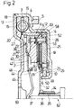
- the design of the dual mass flywheel according to FIG. 2 differs of that of Fig. 1 essentially in that the radially after inside running wall 4 of the first flywheel 1 another axial extension 9 and on this a further wall 19 on the output side that runs radially inwards connects.
- This wall 19 is in the radially inner region, which is radially inside the Friction discs 33 of the clutch disc 32 ends in the direction of the latter provided with a bend 49, whereby an axial section 50 is formed. Due to the bend 49 in connection with the axial section 50 Recording 6 for storage 10 formed.
- the storage 10 in the Recording 6 is secured against axial movement, carries the radially outside Backing plate 25, on one end a shoulder 26 and the other end with the counter-pressure plate 25 non-rotatable disc 29 for securing the axial Backing plate 25 is provided. Because the dual mass flywheel according to Fig. 2 otherwise corresponds to that already described in detail in Fig. 1 no further details on this version.
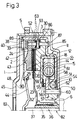
- Fig. 3 another dual mass flywheel is shown, in which the first Inertia 1 except for the radially outward wall 2 and the axial approach 3 has the radially inwardly extending wall 4, at the radial inner end via rivets 60, the receptacle 6 is provided for the storage 10.
- the receptacle 6 has a in the region of its axial section 50 Axial securing for the bearing 10 by the latter on its in Fig. 3rd on the left side of a shoulder of the receptacle 6 and on its right side a spacer ring 62 L-shaped cross section is held.
- the second flywheel 11 Radially outside the bearing 10, the second flywheel 11 by this on its radial inner section 12 has a shoulder 51 at its radially inner end, through which one side of the bearing 10 can be supported while the other Side thereof by one on the radially inner section 14 of the second Flywheel 11 welded disc 54 against the flywheel 11 against Secures axial movement.
- a cover plate 59 On the second flywheel 11 is on the axial Section 12 a cover plate 59 over a likewise axially extending section the same attached, that on its side facing the clutch disc 32 is guided radially inwards.
- a seal 23 At the radially inner end of this cover plate 59 is a seal 23 is provided, which faces away from the cover plate 59 Side on a torque transmitter 58, which via the rivet 60 on the Recording 6 is attached, comes to the plant.
- the seal 23 is by a formed on the side of the cover plate 59 facing her nose 55, a Axial spring 56 and a sealing element 57 are formed.
- the axial spring 56 is supported here radially inside on the sealing element 57 and radially outside on the nose 55 of the Cover plate 59 from. This will at the junction Nose 55 / axial spring 56 a first seal and at the connection point Axial spring 56 / sealing element 57 formed a second sealing point.
- the Seal 23 closes a grease chamber 22, which from the cover plate 59, the radially inner section 14 of the second flywheel 11, the bearing 10, the receptacle 6 and the torque transmitter 58, which in the fat chamber 22nd protrudes, is formed.
- the torque transmitter 58 acts with that in the Grease chamber 22 arranged spring device 15 and the sliding shoes 18 in 1 already based on the radial effective there as a moment carrier outer section 13 of the second flywheel 11 described manner together, with the moment carrier 58 with recesses 61 for the Spring device 15 is provided.
- the fat chamber 22 is in communication with the spring device 15, the torque transmitter 58 and one not shown friction device formed a torsional damper device 20.
- the axial section 12 of the second flywheel 11 is included section 85 running radially outwards, which in turn after bending into a further axial section 86 running in the direction of the wall 2 transforms.
- Rivet 87 attached to the backing plate 25 and one end of elastic means 30.
- the other end of the elastic means 30 is with the other rivets 89
- Pressure plate 24 connected between itself and the pressure plate 25 in already described, the friction linings 33 of the clutch disc 32nd records.
- the pressure plate 24 projects radially outside the friction linings 33 in the axial direction this away.
- Abrasion that has arisen are both in this axial approach Pressure plate 24 as well as in the axial section 86 of the second flywheel 11 and in the axial section 3 of the first flywheel 1
- Through openings 63 are provided, which act as recess 52 for abrasion are effective, due to the centrifugal force when the Dual mass flywheel radially outward about its central axis 83 is thrown and in this way leave the dual mass flywheel can.
- This planet carrier 67 is in the radially outer area firmly connected to a further planet carrier 67, the two planet carriers 67 are arranged at an axial distance from one another and between them
- a plurality of sun gear 68 which is received in a rotationally fixed manner on the receptacle 6 of planet gears 73, the rivets 70, these surrounding sleeves 71 and needle bearings 72 are held and enclose a ring gear 74 as gears.
- the Ring gear 74 has recesses 95 for the spring device in the radially outer region 15, which has sliding shoes 18 between each two springs and is supported at the other end on control elements on the inside of the planet carrier 67 are attached.
- the planet carrier 67 on the left in FIG. 4 is connected to the counterpressure plate via rivets 92 25 firmly connected, which in turn in the manner already described for FIG elastic means 30 is connected to the pressure plate 24.
- the bearing 10 Through the planet carrier 67, the bearing 10 and the receptacle 6 is a Gears 68, 73 and 74 enveloping fat chamber 22 are formed.
- the bearing 10 is formed sealingly, so that at its Fat chamber 22 facing side incoming viscous medium not outdoors can reach.
Landscapes
- Engineering & Computer Science (AREA)
- General Engineering & Computer Science (AREA)
- Physics & Mathematics (AREA)
- Acoustics & Sound (AREA)
- Aviation & Aerospace Engineering (AREA)
- Mechanical Engineering (AREA)
- Mechanical Operated Clutches (AREA)
Description
- Fig. 1
- eine Hälfte eines Zweimassenschwungrades oberhalb der Mittellinie in Schnittdarstellung mit Torsionsdämpfereinrichtung in der ersten Schwungmasse und Anordnung einer Lagerung zwischen der letzteren und einer zweiten Schwungmasse radial außerhalb einer Anfahr- und Schaltkupplung, allerdings noch ohne Darstellung des Erfindungsgegenstandes;
- Fig. 2
- wie Fig. 1, aber mit Anordnung der Lagerung radial innerhalb der Anfahr- und Schaltkupplung als Teil des Erfindungsgegenstandes;
- Fig. 3
- wie Fig. 2, aber mit Ausbildung der Torsionsdämpfereinrichtung in der zweiten Schwungmasse;
- Fig. 4
- wie Fig. 3, aber mit Ausbildung der Torsionsdämpfereinrichtung mit einem Planetengetriebe;
- Fig. 5
- eine vergrößerte Herauszeichnung einer mit der zweiten Schwungmasse verbundenen Gegendruckplatte, die eine Ausnehmung zur Aufnahme von Abrieb aufweist.
Claims (13)
- Zweimassenschwungrad mit einer antriebsseitigen ersten Schwungmasse (1) und einer gegenüber dieser drehbar gelagerten abtriebsseitigen zweiten Schwungmasse (11), mit einer Anfahr- und Schaltkupplung, die mit einer Kupplungsscheibe (32) versehen ist, die ihre Auflagestelle vorzugsweise auf einer abtriebsseitigen Getriebewelle (35) aufweist und in eingerücktem Zustand unter der Wirkung einer eine Druckplatte (24) in der einer Gegendruckplatte (25) zugewandten Richtung belastenden Anpreßfeder (42) steht, sowie mit einer Ausrückvorrichtung (36) zum Aufheben der Wirkung der Anpreßfeder (42), und mit einer Torsionsdämpfereinrichtung (20) mit mindestens einer zwischen den Schwungmassen (1,11) angeordneten Federeinrichtung (15), wobei die zweite Schwungmasse (11) zur drehfesten Aufnahme zumindest einer der in Umfangsrichtung synchron zueinander bewegbaren Platten, wie Druckplatte (24) oder Gegendruckplatte (25) zur Bildung einer modulartigen Einheit (93) vorgesehen ist und die Druckplatte (24) die antriebsseitige Platte, die Gegendruckplatte (25) dagegen die abtriebsseitige Platte bildet, die Anpreßfeder (42) antriebsseitig in Achsrichtung zwischen der ersten Schwungmasse (1) und der Druckplatte (24) angeordnet und an einer Abstützung (38) der zweiten Schwungmasse (11) angelagert ist, zur Beaufschlagung der Druckplatte (24) mit einer Axialkraft in einer der Getriebewelle (35) zugewandten Richtung dient, und der Ausrücker (82) eine radial innerhalb der Auflagestelle der Kupplungscheibe (32) in Richtung zur ersten Schwungmasse (1) durchgreifende und mit der Anpreßfeder (42) in Wirkverbindung bringbare Ausrückvorrichtung (36) aufweist,
dadurch gekennzeichnet,
daß die erste Schwungmasse (1) im Umfangsbereich an deren getriebewellenseitigem Ende eine im wesentlichen nach radial innen laufende abtriebsseitige Wand (19) aufweist, die in einen Bereich radial innerhalb der zweiten Schwungmasse (11) greift, in welchem sie als Aufnahme (6) einer Lagerung (10) für die zweite Schwungmasse (11) wirksam ist, wobei an der Aufnahme (6) ein zumindest in diesem Bereich axial zwischen Kupplungsscheibe (32) und abtriebsseitiger Wand (19) der ersten Schwungmasse (1) greifender, nach radial außen verlaufender Momentenüberträger (58) vorgesehen ist, der an der sich an der zweiten Schwungmasse (11) abstützenden Federeinrichtung (15) in Anlage kommt. - Zweimassenschwungrad nach Anspruch 1 mit einem die abtriebsseitige Wand radial außen aufnehmenden, sich im wesentlichen axial in Richtung zur Getriebewelle erstreckenden Ansatz,
dadurch gekennzeichnet,
daß der Ansatz (3,9) die zweite Schungmasse (11) in Achsrichtung überragt. - Zweimassenschwungrad nach Anspruch 1,
dadurch gekennzeichnet,
daß die abtriebsseitige Wand (19) an der der Getriebewelle (35) zugewandten Seite der Kupplungsscheibe (32) als Lagerung (10) dient. - Zweimassenschwungrad nach Anspruch 1,
dadurch gekennzeichnet,
daß die Aufnahme (6) für die Lagerung (10) an der ersten Schwungmasse (1) durch eine Umbiegung (49) am radial inneren Ende der abtriebsseitigen Wand (19) in Richtung zur Kupplungsscheibe (32) gebildet wird. - Zweimassenschwungrad nach Anspruch 1,
dadurch gekennzeichnet,
daß die Lagerung (10) die zweite Schwungmasse (11) über die Gegendruckplatte (25) aufnimmt. - Zweimassenschwungrad nach Anspruch 1,
dadurch gekennzeichnet,
daß die Lagerung (10) die zweite Schwungmasse (11) über zumindest einen Planetenträger (67) eines als Zwischenmasse (76) wirksamen Planetengetriebes (75) aufnimmt. - Zweimassenschwungrad nach Anspruch 6,
dadurch gekennzeichnet,
daß der Planetenträger (67) einerseits mit der zweiten Schwungmasse (11) und andererseits mit der Gegendruckplatte (25) fest verbunden ist. - Zweimassenschwungrad nach Anspruch 1 und 7 mit zwei zueinander mit Axialversatz angeordneten Planetenträgern,
dadurch gekennzeichnet,
daß die Planetenträger (67) zusammen mit dem lagertragenden, radial inneren Bereich der abtriebsseitigen Wand (19) der ersten Schwungmasse (1) eine Fettkammer (22) für die Torsionsdämpfereinrichtung (20) bilden. - Zweimassenschwungrad nach Anspruch 1,
dadurch gekennzeichnet,
daß der abtriebsseitigen Wand (4,19) der ersten Schwungmasse (1) ein axial beabstandetes Deckblech (59) drehfest zugeordnet ist, das zusammen mit der Wand (19) und der Lagerung (10) eine Fettkammer (22) für die Torsionsdämpfereinrichtung (20) bildet. - Zweimassenschwungrad nach Anspruch 1 und 9,
dadurch gekennzeichnet,
daß das Deckblech (59) als Anlage für die mit der zweiten Schwungmasse (11) verbundene Gegendruckplatte (25) dient. - Zweimassenschwungrad nach Anspruch 1, bei dem zumindest eine der Schwungmassen (1,11) benachbart zu den Reibbelägen (33) der Kupplungsscheibe (32) wenigstens eine Ausnehmung (52) für Abrieb der Reibbeläge (33) aufweist,
dadurch gekennzeichnet,
daß die Ausnehmung (52) als Kammer (53) in die jeweilige Schwungmasse (11) eingearbeitet ist, wobei das Kammervolumen der maximal entstehenden Abriebmenge angepaßt ist. - Zweimassenschwungrad nach Anspruch 11,
dadurch gekennzeichnet,
daß der Ausnehmung (52) ein Leitblech (80) für vom Reibbelag (33) der Kupplungscheibe (32) gelösten Abtrieb zugeordnet ist. - Zweimassenschwungrad nach Anspruch 1,
dadurch gekennzeichnet,
daß die an der zweiten Schwungmasse (11) ausgebildete Abstützung (38) angrenzend an die erste Schwungmasse (1) nach radial innen greifende Vorsprünge (40) zur Anlagerung der Anpreßfeder (42) mit deren von der Druckplatte (24) abgewandten Seite aufweist.
Applications Claiming Priority (2)
| Application Number | Priority Date | Filing Date | Title |
|---|---|---|---|
| DE19502617A DE19502617C2 (de) | 1995-01-27 | 1995-01-27 | Zweimassenschwungrad mit motorseitig angeordneter Druckplatte |
| DE19502617 | 1995-01-27 |
Publications (2)
| Publication Number | Publication Date |
|---|---|
| EP0724092A1 EP0724092A1 (de) | 1996-07-31 |
| EP0724092B1 true EP0724092B1 (de) | 1998-07-22 |
Family
ID=7752496
Family Applications (1)
| Application Number | Title | Priority Date | Filing Date |
|---|---|---|---|
| EP95118411A Expired - Lifetime EP0724092B1 (de) | 1995-01-27 | 1995-11-23 | Zweimassenschwungrad mit motorseitig angeordneter Druckplatte |
Country Status (3)
| Country | Link |
|---|---|
| EP (1) | EP0724092B1 (de) |
| DE (2) | DE19502617C2 (de) |
| ES (1) | ES2119294T3 (de) |
Families Citing this family (10)
| Publication number | Priority date | Publication date | Assignee | Title |
|---|---|---|---|---|
| DE19817910B4 (de) * | 1998-04-22 | 2014-11-20 | Rohs-Voigt Patentverwertungsgesellschaft Mbh | Torsionsschwingungsdämpfer und Verfahren zu dessen Herstellung |
| DE19964461B4 (de) * | 1999-05-12 | 2013-02-21 | Borgwarner Inc. | Mehrfach-Kupplungssystem für ein Getriebe |
| DE19921687C5 (de) * | 1999-05-12 | 2016-06-09 | Borgwarner Inc. | Mehrfach-Kupplungssystem für ein Getriebe |
| US6634866B2 (en) | 2001-08-17 | 2003-10-21 | Borgwarner, Inc. | Method and apparatus for providing a hydraulic transmission pump assembly having a one way clutch |
| US6588559B2 (en) | 2001-09-18 | 2003-07-08 | Borgwarner, Inc. | Two-way clutch biasing assembly |
| US6554113B2 (en) | 2001-09-20 | 2003-04-29 | Borgwarner, Inc. | Torque limiting accessory drive assembly |
| GB0126726D0 (en) * | 2001-11-07 | 2002-01-02 | Ap Tmf Ltd | Twin mass flywheel |
| DE102006052101A1 (de) * | 2006-11-04 | 2008-05-08 | Zf Friedrichshafen Ag | Einrichtung zur Kapselung von Kupplungs-Feinstäuben |
| DE102013226939A1 (de) * | 2013-12-20 | 2015-06-25 | Zf Friedrichshafen Ag | Drehschwingungsdämpfungsanordnung für den Antriebsstrang eines Fahrzeugs |
| DE102020110377B3 (de) | 2020-04-16 | 2021-07-08 | Schaeffler Technologies AG & Co. KG | Trennkupplung mit Schmutzleitblechen; sowie Antriebseinheit |
Family Cites Families (11)
| Publication number | Priority date | Publication date | Assignee | Title |
|---|---|---|---|---|
| DE2824718A1 (de) * | 1978-06-06 | 1980-02-28 | Luk Lamellen & Kupplungsbau | Einer brennkraftmaschine nachgeschaltete schwungmasse |
| US4287977A (en) * | 1978-10-28 | 1981-09-08 | Toyota Jidosha Kogyo Kabushiki Kaisha | Hydraulic clutch release mechanism |
| DE3347913A1 (de) * | 1983-03-25 | 1985-06-27 | LuK Lamellen und Kupplungsbau GmbH, 7580 Bühl | Reibungskupplung |
| DE3335982A1 (de) * | 1983-10-04 | 1985-04-18 | Volkswagenwerk Ag, 3180 Wolfsburg | Elastische wellenkupplung |
| DE3610127C2 (de) * | 1985-06-14 | 1994-04-28 | Gkn Automotive Ag | Drehelastische, schwingungsdämpfende Schwungscheibe |
| DE3612419A1 (de) * | 1986-04-12 | 1987-10-22 | Schaeffler Waelzlager Kg | Lagerung eines kupplungshebels an kraftfahrzeugen |
| FR2654784B1 (fr) * | 1989-11-20 | 1992-02-07 | Valeo | Module d'embrayage, notamment pour vehicule automobile. |
| FR2662759B1 (fr) * | 1990-05-31 | 1996-04-12 | Luk Lamellen & Kupplungsbau | Dispositif de transmission de couple. |
| DE4214655C2 (de) * | 1991-06-01 | 2003-02-27 | Luk Lamellen & Kupplungsbau | Wälzlager |
| DE9313557U1 (de) * | 1993-09-08 | 1993-10-28 | INA Wälzlager Schaeffler KG, 91074 Herzogenaurach | Ausrückvorrichtung für eine Reibungsklupplung |
| DE4447629C2 (de) * | 1993-12-22 | 1997-09-11 | Fichtel & Sachs Ag | Torsionsschwingungsdämpfer mit einem Planetengetriebe |
-
1995
- 1995-01-27 DE DE19502617A patent/DE19502617C2/de not_active Expired - Fee Related
- 1995-11-23 ES ES95118411T patent/ES2119294T3/es not_active Expired - Lifetime
- 1995-11-23 DE DE59502885T patent/DE59502885D1/de not_active Expired - Fee Related
- 1995-11-23 EP EP95118411A patent/EP0724092B1/de not_active Expired - Lifetime
Also Published As
| Publication number | Publication date |
|---|---|
| DE19502617C2 (de) | 1998-09-17 |
| DE59502885D1 (de) | 1998-08-27 |
| DE19502617A1 (de) | 1996-08-08 |
| ES2119294T3 (es) | 1998-10-01 |
| EP0724092A1 (de) | 1996-07-31 |
Similar Documents
| Publication | Publication Date | Title |
|---|---|---|
| EP1522753B1 (de) | Hydraulische Doppelkupplung | |
| DE10034677B4 (de) | Mehrfachkupplungsanordnung | |
| DE19654894B4 (de) | Torsionsschwingungsdämpfer mit einer Ausgleichsschwungmasse | |
| DE102009059942A1 (de) | Mehrfachkupplungsvorrichtung | |
| DE112016002922T5 (de) | Drehmomentschwankungs-Verhinderungsvorrichtung, Drehmomentwandler und Kraftübertragungsvorrichtung | |
| EP1134447B1 (de) | Doppelkupplungsanordnung | |
| DE3642909C2 (de) | Einrichtung zum Kompensieren von Drehstößen | |
| DE19525842C2 (de) | Torsionsschwingungsdämpfer mit variabler Übersetzung | |
| DE19727678C2 (de) | Torsionsschwingungsdämpfer mit einem Planetengetriebe mit wenigstens einem Verzahnungselement | |
| DE10013576B4 (de) | Kupplungsaggregat | |
| DE19502617C2 (de) | Zweimassenschwungrad mit motorseitig angeordneter Druckplatte | |
| DE19616329C2 (de) | Reibungskupplung zur Anordnung im Antriebsstrang eines Kraftfahrzeugs | |
| DE112006002790B4 (de) | Hydrodynamische Drehmomentwandler-Vorrichtung mit einer Lamellenkupplung | |
| EP3070358B1 (de) | Doppelkupplung | |
| EP1614919B1 (de) | Kupplungsanordnung | |
| DE102008038100A1 (de) | Lamellenkupplung mit einem hydraulisch antreibbaren Betätigungskolben | |
| DE102007027122A1 (de) | Kupplungshauptnabe bzw. Doppelkupplung mit einer derartigen Kupplungshauptnabe | |
| DE19644173C1 (de) | Torsionsschwingungsdämpfer mit einem Verschluß für Öffnungen zum Befüllen der Fettkammer | |
| DE102004039905A1 (de) | Schwingungsdämpfungssystem | |
| DE19861365B4 (de) | Torsionsschwingungsdämpfer mit zumindest einer Lagerung zwischen Dämpferelementen | |
| DE102017130853B4 (de) | Kupplungseinrichtung | |
| DE102009017255A1 (de) | Kupplungsaggregat | |
| EP1826459A1 (de) | Drehmomentwandler mit Überbrückungskupplung | |
| DE102006060738B4 (de) | Doppelkupplungsvorrichtung | |
| EP1647729A2 (de) | Kupplungsscheibenanordnung für eine Mehrscheibenkupplung |
Legal Events
| Date | Code | Title | Description |
|---|---|---|---|
| PUAI | Public reference made under article 153(3) epc to a published international application that has entered the european phase |
Free format text: ORIGINAL CODE: 0009012 |
|
| AK | Designated contracting states |
Kind code of ref document: A1 Designated state(s): DE ES FR GB |
|
| 17P | Request for examination filed |
Effective date: 19960827 |
|
| 17Q | First examination report despatched |
Effective date: 19961230 |
|
| GRAG | Despatch of communication of intention to grant |
Free format text: ORIGINAL CODE: EPIDOS AGRA |
|
| GRAG | Despatch of communication of intention to grant |
Free format text: ORIGINAL CODE: EPIDOS AGRA |
|
| GRAH | Despatch of communication of intention to grant a patent |
Free format text: ORIGINAL CODE: EPIDOS IGRA |
|
| GRAH | Despatch of communication of intention to grant a patent |
Free format text: ORIGINAL CODE: EPIDOS IGRA |
|
| RAP1 | Party data changed (applicant data changed or rights of an application transferred) |
Owner name: MANNESMANN SACHS AKTIENGESELLSCHAFT |
|
| GRAA | (expected) grant |
Free format text: ORIGINAL CODE: 0009210 |
|
| AK | Designated contracting states |
Kind code of ref document: B1 Designated state(s): DE ES FR GB |
|
| GBT | Gb: translation of ep patent filed (gb section 77(6)(a)/1977) |
Effective date: 19980723 |
|
| REF | Corresponds to: |
Ref document number: 59502885 Country of ref document: DE Date of ref document: 19980827 |
|
| ET | Fr: translation filed | ||
| REG | Reference to a national code |
Ref country code: ES Ref legal event code: FG2A Ref document number: 2119294 Country of ref document: ES Kind code of ref document: T3 |
|
| PLBE | No opposition filed within time limit |
Free format text: ORIGINAL CODE: 0009261 |
|
| STAA | Information on the status of an ep patent application or granted ep patent |
Free format text: STATUS: NO OPPOSITION FILED WITHIN TIME LIMIT |
|
| 26N | No opposition filed | ||
| REG | Reference to a national code |
Ref country code: GB Ref legal event code: IF02 |
|
| PGFP | Annual fee paid to national office [announced via postgrant information from national office to epo] |
Ref country code: GB Payment date: 20031029 Year of fee payment: 9 |
|
| PGFP | Annual fee paid to national office [announced via postgrant information from national office to epo] |
Ref country code: ES Payment date: 20031119 Year of fee payment: 9 |
|
| PG25 | Lapsed in a contracting state [announced via postgrant information from national office to epo] |
Ref country code: GB Free format text: LAPSE BECAUSE OF NON-PAYMENT OF DUE FEES Effective date: 20041123 |
|
| PG25 | Lapsed in a contracting state [announced via postgrant information from national office to epo] |
Ref country code: ES Free format text: LAPSE BECAUSE OF NON-PAYMENT OF DUE FEES Effective date: 20041124 |
|
| GBPC | Gb: european patent ceased through non-payment of renewal fee |
Effective date: 20041123 |
|
| PGFP | Annual fee paid to national office [announced via postgrant information from national office to epo] |
Ref country code: DE Payment date: 20051110 Year of fee payment: 11 |
|
| REG | Reference to a national code |
Ref country code: ES Ref legal event code: FD2A Effective date: 20041124 |
|
| PG25 | Lapsed in a contracting state [announced via postgrant information from national office to epo] |
Ref country code: DE Free format text: LAPSE BECAUSE OF NON-PAYMENT OF DUE FEES Effective date: 20070601 |
|
| PGFP | Annual fee paid to national office [announced via postgrant information from national office to epo] |
Ref country code: FR Payment date: 20081112 Year of fee payment: 14 |
|
| REG | Reference to a national code |
Ref country code: FR Ref legal event code: ST Effective date: 20100730 |
|
| PG25 | Lapsed in a contracting state [announced via postgrant information from national office to epo] |
Ref country code: FR Free format text: LAPSE BECAUSE OF NON-PAYMENT OF DUE FEES Effective date: 20091130 |