EP0722801B1 - Bohrer - Google Patents
Bohrer Download PDFInfo
- Publication number
- EP0722801B1 EP0722801B1 EP96300386A EP96300386A EP0722801B1 EP 0722801 B1 EP0722801 B1 EP 0722801B1 EP 96300386 A EP96300386 A EP 96300386A EP 96300386 A EP96300386 A EP 96300386A EP 0722801 B1 EP0722801 B1 EP 0722801B1
- Authority
- EP
- European Patent Office
- Prior art keywords
- drill
- push rod
- expansible
- drill body
- arm
- Prior art date
- Legal status (The legal status is an assumption and is not a legal conclusion. Google has not performed a legal analysis and makes no representation as to the accuracy of the status listed.)
- Expired - Lifetime
Links
- 238000005553 drilling Methods 0.000 claims abstract description 17
- 239000012530 fluid Substances 0.000 claims description 3
- XLYOFNOQVPJJNP-UHFFFAOYSA-N water Substances O XLYOFNOQVPJJNP-UHFFFAOYSA-N 0.000 description 10
- 239000000463 material Substances 0.000 description 3
- 230000036346 tooth eruption Effects 0.000 description 3
- 230000000295 complement effect Effects 0.000 description 2
- 238000001816 cooling Methods 0.000 description 2
- 239000000428 dust Substances 0.000 description 2
- 229910000906 Bronze Inorganic materials 0.000 description 1
- 239000010974 bronze Substances 0.000 description 1
- 230000006835 compression Effects 0.000 description 1
- 238000007906 compression Methods 0.000 description 1
- 239000002826 coolant Substances 0.000 description 1
- KUNSUQLRTQLHQQ-UHFFFAOYSA-N copper tin Chemical compound [Cu].[Sn] KUNSUQLRTQLHQQ-UHFFFAOYSA-N 0.000 description 1
- 238000005260 corrosion Methods 0.000 description 1
- 230000007797 corrosion Effects 0.000 description 1
- 229910003460 diamond Inorganic materials 0.000 description 1
- 239000010432 diamond Substances 0.000 description 1
- 230000000694 effects Effects 0.000 description 1
- 238000011065 in-situ storage Methods 0.000 description 1
- 239000007788 liquid Substances 0.000 description 1
- 238000000034 method Methods 0.000 description 1
- 238000011084 recovery Methods 0.000 description 1
- 230000000284 resting effect Effects 0.000 description 1
- 229910001220 stainless steel Inorganic materials 0.000 description 1
- 239000010935 stainless steel Substances 0.000 description 1
Images

Classifications
-
- B—PERFORMING OPERATIONS; TRANSPORTING
- B23—MACHINE TOOLS; METAL-WORKING NOT OTHERWISE PROVIDED FOR
- B23B—TURNING; BORING
- B23B51/00—Tools for drilling machines
- B23B51/0018—Drills for enlarging a hole
- B23B51/0045—Drills for enlarging a hole by expanding or tilting the toolhead
-
- Y—GENERAL TAGGING OF NEW TECHNOLOGICAL DEVELOPMENTS; GENERAL TAGGING OF CROSS-SECTIONAL TECHNOLOGIES SPANNING OVER SEVERAL SECTIONS OF THE IPC; TECHNICAL SUBJECTS COVERED BY FORMER USPC CROSS-REFERENCE ART COLLECTIONS [XRACs] AND DIGESTS
- Y10—TECHNICAL SUBJECTS COVERED BY FORMER USPC
- Y10T—TECHNICAL SUBJECTS COVERED BY FORMER US CLASSIFICATION
- Y10T408/00—Cutting by use of rotating axially moving tool
- Y10T408/83—Tool-support with means to move Tool relative to tool-support
- Y10T408/85—Tool-support with means to move Tool relative to tool-support to move radially
- Y10T408/858—Moving means including wedge, screw or cam
- Y10T408/8588—Axially slidable moving-means
- Y10T408/85884—Tool pivotally mounted on support
-
- Y—GENERAL TAGGING OF NEW TECHNOLOGICAL DEVELOPMENTS; GENERAL TAGGING OF CROSS-SECTIONAL TECHNOLOGIES SPANNING OVER SEVERAL SECTIONS OF THE IPC; TECHNICAL SUBJECTS COVERED BY FORMER USPC CROSS-REFERENCE ART COLLECTIONS [XRACs] AND DIGESTS
- Y10—TECHNICAL SUBJECTS COVERED BY FORMER USPC
- Y10T—TECHNICAL SUBJECTS COVERED BY FORMER US CLASSIFICATION
- Y10T408/00—Cutting by use of rotating axially moving tool
- Y10T408/83—Tool-support with means to move Tool relative to tool-support
- Y10T408/85—Tool-support with means to move Tool relative to tool-support to move radially
- Y10T408/858—Moving means including wedge, screw or cam
- Y10T408/8595—Pivotable tool-support
-
- Y—GENERAL TAGGING OF NEW TECHNOLOGICAL DEVELOPMENTS; GENERAL TAGGING OF CROSS-SECTIONAL TECHNOLOGIES SPANNING OVER SEVERAL SECTIONS OF THE IPC; TECHNICAL SUBJECTS COVERED BY FORMER USPC CROSS-REFERENCE ART COLLECTIONS [XRACs] AND DIGESTS
- Y10—TECHNICAL SUBJECTS COVERED BY FORMER USPC
- Y10T—TECHNICAL SUBJECTS COVERED BY FORMER US CLASSIFICATION
- Y10T408/00—Cutting by use of rotating axially moving tool
- Y10T408/89—Tool or Tool with support
- Y10T408/905—Having stepped cutting edges
- Y10T408/906—Axially spaced
-
- Y—GENERAL TAGGING OF NEW TECHNOLOGICAL DEVELOPMENTS; GENERAL TAGGING OF CROSS-SECTIONAL TECHNOLOGIES SPANNING OVER SEVERAL SECTIONS OF THE IPC; TECHNICAL SUBJECTS COVERED BY FORMER USPC CROSS-REFERENCE ART COLLECTIONS [XRACs] AND DIGESTS
- Y10—TECHNICAL SUBJECTS COVERED BY FORMER USPC
- Y10T—TECHNICAL SUBJECTS COVERED BY FORMER US CLASSIFICATION
- Y10T82/00—Turning
- Y10T82/12—Radially moving rotating tool inside bore
Definitions
- the invention relates to improvements in drills for drilling and undercutting holes.
- GB-A-2184962 describes an expansible drill for forming an undercut.
- the drill disclosed in this document comprises a cylinder having an incorporated cutting edge at one end.
- the end of the cylinder is slotted and can be expanded by tightening a nut on the end of the central shaft sticking out of the bore. This forces a frusto-conical wedge inside the slotted end of the cylinder causing it to expand radially.
- GB-A-2157207 also discloses an undercutting drill.
- the blades carrying the cutting teeth of this drill are flexible and are forced to expand radially as the body of the drill is forced over the conical guide. The latter is effected by pushing the drill against the bottom of the bore so that the guide, which is movable axially relative to the drill body, can move no further and the blades thus slide over the guide sides and consequently are expanded.
- a collar is described which bears on the outer surface of the material having the bore. The collar is fixed to the lower half of the drill body, whilst the upper half is movable relative thereto in an axial direction.
- US-A-2,236,944 discloses a drill bit for drilling inverted counterbore holes.
- This drill has a rotating drill body with radially extending arms attached at one end.
- a shaft which is constrained to rotate with the drill body, is movable longitudinally relative to the drill body and has a ball-head which causes the arms to extend outwardly when it comes into contact therewith. Movement of the shaft is effected by an external handle which, when moved, causes a rotating collar to move against a spring positioned between a stepped portion of the drill body and the collar.
- the obvious disadvantage with this arrangement is that dust and debris from the drilling operation will effect the movement of the spring, the rotating collar and the handle thereby causing it to jam.
- GB-A-2246089 discloses a drill for forming an undercut in a cylindrical bore which overcomes the disadvantages listed above.
- This drill incorporates a trigger which can be squeezed towards a handle to move a non-rotating shaft axially relative to the drill body rotating within the bore.
- a collar mounted on the shaft travels along in contact with the inner surface of cutting arms which pivot out from recesses within the drill body thereby expanding the drill to cut a conical shaped undercut.
- the trigger is pulled away from the handle which retracts the shaft and allows the arms to pivot inwards to their original position.
- the trigger provides a high degree of control and accuracy in expanding the drill.
- GB-A-2248200 discloses a drill for forming a bore and undercutting it.
- This drill has a rotatable tubular drill body having a drill head which enables the parallel walled bore to be drilled.
- the second set of cutting means are provided which comprise a pair of pivotal arms positioned within slots cut axially in the body which arms are provided with external cutting teeth.
- the drill also has a non-rotating shaft which is axially slidable within the drill body which, when moved relative to the drill body as in GB-A-2246089, causes the pivotal arms to swing radially outwards to undercut the previously cut bore.
- an expansible drill for drilling and/or undercutting holes comprising a rotatable tubular drill body having bore cutting means at one end thereof, at least one undercutting arm located within a slot in the drill body attached by hinge means such that at least a part of the arm is pivotal radially outwards, a push rod located within the drill body for moving the arm radially outwards, characterised in that said push rod is constrained to rotate therewith, the drill further comprising locking means for selectively preventing or allowing the push rod to move axially relative to the drill body as force is applied to an end of the push rod.
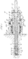
- the drill 10 comprises a hollow rotatable drill body 11.
- the drill body 11 has an internal thread 13 at one end to receive a drill head 14 having a complementary external thread. This will be referred to as the "cutting end" of the drill body 11 and the opposite end will be referred to as the "non-cutting end”.
- the drill head 14 preferably has at least one passage way 15 drilled through it.
- the drill body 11 has one or more axial slots 16 formed towards its cutting end as shown in Fig. 3. Positioned within each slot 16, and hinged to the drill body 11, is an arm 17.
- the hinge can be of any suitable form which allows a major part of the arm 17 to pivot outwards.
- the hinge shown in the drawings comprises a hole 18 drilled through the drill body 11 on either side of the slot and through each arm 17. A pin is then pushed through the holes 18 to hold the arm 17 in place.
- the hinge allows one end of the arm 17 to swing out radially in an arc to form the undercut and the other end of the arm 17 swings inwards.
- the outer surface of each arm 17 has a cutting edge or surface 19 formed, for example, with cutting teeth or impregnated with industrial diamond.
- the cutting surface 19 preferably extends along the major part of the arm 17 which pivots radially outwards.
- the drill 10 has three arms 17 equally spaced about the circumference of the drill body 11, although the invention is not limited to this number.
- the inner surface of each arm 17 curves inwardly so as to form a cam surface 20 towards the cutting end of the arm 17.
- the drill body 11 has, at its non-cutting end, an external thread 22 which enables it to be screwed into a sleeve 23 having a complementary internal thread at one end.
- the drill 10 also comprises a push rod 12 which extends through the drill body 11 and sleeve 23.
- the drill body 11 receives a front end of the push rod 12, whilst the sleeve 23 surrounds a middle portion of the push rod 12.
- the push rod 12 has, at its front end, a bulb-like tip 25 which is rounded and narrows to form a neck where it is attached to the push rod 12. This neck receives the parts of the arms 17 which swing inwards during undercutting.
- a passage way 26 which is preferably Y-shaped extending axially and separating to form a pair of transverse branches through the sides of the neck, as shown in Fig. 1. This passage way 26 permits the flow of water through the tip 25 into the bore.
- the rear end 27 of the push rod 12 which projects from the sleeve 23 is shaped for attachment to driving means, such as a power drill. This can be in the form of one or more flattened surfaces 28.
- driving means such as a power drill.
- This can be in the form of one or more flattened surfaces 28.
- the surface of the push rod 12 located within the drill body 11, adjacent the tip 25, also has one or more flattened surfaces to allow the passage of water along the push rod 12 to the tip 25.
- a flange 32 Located along the middle portion of the push rod 12 is a flange 32 and a section 24 of greater diameter than the rest of the push rod 12. An aperture 29 is drilled through the section 24. When the sleeve 23 is positioned about the push rod 12, a pin 30 is placed through the aperture 29 and a slot 35 in the sleeve 23.
- a compression spring 33 is located around the middle portion of the push rod 12, so that it will lie within the bore of the sleeve 23.
- One end of the spring 33 abuts against the drill body 11 where it is screwed into the sleeve 23 and the other end against the flange 32.
- the spring 33 is biased so that when it is in its resting position, the tip of push rod 12 lies behind the cam surface 20 on the back of the arms 17 and they lie within the slots 16.
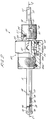
- the sleeve 23 has a neck 39, of reduced diameter, in which is located a transverse hole 34. This forms part of the water passage way, which is described in full below.
- the sleeve 23 also has a locating flange 42.
- a collar 40 Mounted on the rear end of the sleeve 23, abutting the locating flange 42, is a collar 40 which has, on each side, an L-shaped aperture 41.
- the pin 30 which passes through the push rod 12 and the sleeve 23, also passes through the apertures 41 in the collar.
- the collar 40 is rotatable and axially slidable relative to the sleeve 23, but its movement is limited by movement of the pin 30 within the L-shaped aperture 41.
- Catch means are provided in the form of a pair of holes 36 drilled part way into opposite sides of the sleeve 23, each of which receives a spring 37 and ball bearing 38 which bear against the collar 40.
- the inner surface of the collar 40 has a pair of detents to receive the ball bearings 38, when the collar 40 is in its bore drilling position. The catch means help to hold the collar 40 in that position.
- a thrust bearing housing 45 Also mounted on the sleeve 23, abutting against an opposite side of the flange 42 to the collar 40, is a thrust bearing housing 45.
- the housing 45 comprises an outer part 45a and an inner part 45b.
- the housing inner part 45b is directly mounted on the sleeve 23. The fit is such that there is no relative movement therebetween.
- Sandwiched between the housing parts 45a, 45b is a thrust bearing 46.
- the bearing 46 allows the housing outer part 45a to remain stationary, whilst the sleeve 23 and housing inner part 45b rotate relative thereto.
- the housing outer part 45a has a single aperture 47 to receive a water supply.
- the aperture 47 leads into a chamber 48 between the housing parts 45a, 45b.
- Leading from the chamber 48 through the housing inner part 45b are a series of holes 49 which are located in the vicinity of the neck 39 in the sleeve 23.
- the two parts of the housing 45a, 45b are sealed at each end with appropriate fluid/gas-type seals.
- the drill 10 is first set to drill a cylindrical bore.
- the collar 40 is twisted so that the pin 30 is in the position in the L-shaped apertures 41 shown in Fig. 2.
- the catch means help to hold the collar 40 in this position whereby the pin 30 is restrained at the extreme right-hand end of the slot 35 in sleeve 23.
- This set up permits no relative axial movement between the push rod 12 and the drill body 11/sleeve 23.
- the rear end 27 of the push rod 12 is connected to driving means which drive the push rod 12.
- the pin 30 also constrains the sleeve 23/drill body 11 and collar 40 to rotate with the push rod 12.
- the thrust bearing 46 allows the housing 45 to be held stationary.
- the drill head 14 is placed against the component to be drilled and the drill 10 is pushed into the component until the housing 45 abuts against it.
- the collar 40 is rotated until the pin 30 is at the apex of the L-shaped aperture 41. This allows the pin 30 to move along the longitudinal slots 35 in the sleeve 23 when force is applied to the end of the drill 10. This force causes the push rod 12 to move axially within the sleeve 23, thereby compressing the spring 33. As the push rod 12 moves, the push rod tip 25 travels along in contact with the cam surfaces 20 of the arms 17 such that the cutting ends of the arms 17 are forced outwards whilst the outer ends of the arms 17 swing into the neck behind the tip 25. This causes expansion of the drill 10 to cut a conical shape undercut.
- water whilst drilling, water is supplied through aperture 47 in the outer housing part 45a. This passes into the chamber 48, through the holes 49 in the inner housing part 45b, through the hole 34 in the sleeve 23 and into the gap between the sleeve 23 and the push rod 12.
- Flattened surfaces 31 of the push rod 12 allow the water to travel along the sides of the push rod 12 into a necked region of the push rod tip 25.
- the water then passes into the passageway 26 and out through the passageways 15 in the drill head 14. This flow of water assists in cooling the parts of the drill 10 which may be heated during drilling due to friction and helps to wash away debris caused by drilling.
- the water supply may be replaced by a supply of other fluid, such as coolant, or a gas.
- a vacuum may be applied to extract dust and debris from the drilling cavity and to cause a cooling flow of air flowing in the opposite direction to the one previously described.
- the relaxation of pressure on the end of the drill 10 allows the spring 33 to expand and push the push rod 12 rearwardly.
- the push rod tip 25 moves back out of contact with the arm cam surfaces 20.
- the ends of the arms 17 which are positioned in the neck behind the tip 25 are forced back out, thereby causing the arms 17 to be pulled back within the slots 16.
- the drill body 11 is shown as being a smooth cylinder, it may be fluted to assist the flow of debris away from the bore during drilling. It should also be noted that the drill body 11 can be replaced easily so that different sizes can be used for different size holes.
- the hinge arrangement associated with the arms 17 can be replaced by any other suitable arrangement.
- Another possibility would be to use an O ring located within a groove in the drill body 11. This would enable the arms to easily be changed in the event that the cutting edge is blunted.
- the cutting surface 19 may be integrally formed in the arm 17. Alternatively, disposable tips may be applied.
- the arrangement of the drill 10 is such that as well as plane rotating drilling means, hammer drill action can also be used.
- the parts of the drill may be made from any appropriate material. Especially preferred are stainless steel and bronze to avoid any corrosion due to the flow of water or other liquid in and around the drill 10.
- the drill can be used for both drilling the bore and undercutting, it can quite clearly also be used as just for one operation or the other.
Landscapes
- Engineering & Computer Science (AREA)
- Mechanical Engineering (AREA)
- Processing Of Stones Or Stones Resemblance Materials (AREA)
- Drilling Tools (AREA)
- Golf Clubs (AREA)
Claims (15)
- Expandierbarer Bohrer (10) zum Bohren und/oder Hinterschneiden von Bohrungen mit einem rohrförmigen Bohrerkörper (11) mit Bohrschneidmitteln (14) an seinem einen Ende, wenigstens einem Hinterschneidarm (17), der in einem Schlitz (16) in dem Bohrerkörper aufgenommen ist und mittels Gelenkmitteln so befestigt ist, daß wenigstens ein Teil des Arms radial nach außen schwenkbar ist, einer Stößelstange (12), die im Bohrerkörper angeordnet ist, um den Arm radial nach außen zu bewegen,
dadurch gekennzeichnet, daß die Stößelstange (12) zwangsweise mitdreht, der Bohrer weiterhin Sperrmittel (30, 40, 41) aufweist, um selektiv zu verhindern oder zu erlauben, daß die Stößelstange relativ zum Bohrerkörper axial bewegt wird, wenn auf das Ende der Stößelstange eine Kraft ausgeübt wird. - Expandierbarer Bohrer (10) nach Anspruch 1,
wobei innerhalb der Schlitze (16), die in ein Ende des Bohrerkörpers (11) eingeschnitten sind, drei Arme (17) angeordnet sind. - Expandierbarer Bohrer (10) nach Anspruch 1 oder 2,
wobei eine Innenfläche des Arms oder der Arme (17) und die Stößelstange (12) so profiliert sind, daß die Axialbewegung der Stößelstange relativ zum Bohrerkörper (11) in eine Richtung bewirkt, daß der oder die Arme radial nach außen schwenken. - Expandierbarer Bohrer (10) nach Anspruch 3,
wobei die Stößelstange (12) weiter so profiliert ist, daß die Axialbewegung der Stößelstange relativ zum Bohrerkörper (11) in eine entgegengesetzte Richtung bewirkt, daß der oder die Arme (17) nach innen schwenkt oder schwenken. - Expandierbarer Bohrer (10) nach einem der vorstehenden Ansprüche,
wobei die Stößelstange (12) mit einer Antriebseinrichtung verbunden ist. - Expandierbarer Bohrer (10) nach einem der vorstehenden Ansprüche,
wobei die Sperrmittel (30, 40, 41) einen Kragen (40) aufweisen, der zwischen einer gesperrten Position, in welcher die Stößelstange (12) daran gehindert ist, sich axial relativ zu dem Bohrerkörper (11) zu bewegen, und einer ungesperrten Position, in welcher sich die Stößelstange relativ zu dem Bohrerkörper bewegen kann, drehbar ist. - Expandierbarer Bohrer (10) nach Anspruch 6,
wobei die Sperrmittel (30, 40, 41) weiterhin einen Sperrstift (30) aufweisen, der quer durch die Stößelstange (12), durch wenigstens einen axialen Schlitz (29) in dem Bohrerkörper (11) und durch wenigstens einen Schlitz (41) in dem Kragen geht. - Expandierbarer Bohrer (10) nach Anspruch 7,
wobei der wenigstens eine Schlitz (41) in dem Kragen L-förmig ist und einen Querteil und einen Axialteil hat. - Expandierbarer Bohrer (10) nach einem der vorstehenden Ansprüche, weiterhin mit Federmitteln (33), die so angeordnet sind, daß die Stößelstange in einer Position gehalten wird, so daß der oder die Arme (17) in ihren Schlitzen (16) bleiben.
- Expandierbarer Bohrer (10) nach einem der vorstehenden Ansprüche,
weiterhin mit einem Gehäuse (45), welches ein Drucklager (46) enthält. - Expandierbarer Bohrer (10) nach Anspruch 10,
wobei das Gehäuse (45) einen Innenteil (45b) und einen Außenteil (45a) aufweist, zwischen welchen das Lager (46) liegt. - Expandierbarer Bohrer (10) nach Anspruch 11,
wobei der Innenteil (45b) des Gehäuses (45) auf dem Bohrerkörper (11) liegt. - Expandierbarer Bohrer (10) nach einem der vorstehenden Ansprüche,
wobei der Bohrerkörper (11) zwei Abschnitte aufweist, ein Schneidende, an welchem die Bohrschneidmittel (14) liegen und ein Nichtschneidende, an welchem eine Hülse (23) liegt. - Expandierbarer Bohrer (10) nach einem der vorstehenden Ansprüche,
wobei die Bohrschneidmittel (14) vom Bohrerkörper (11) lösbar sind. - Expandierbarer Bohrer (10) nach einem der vorstehenden Ansprüche,
wobei die Bohrerbauteile Öffnungen und Kanäle (15, 26, 31, 34, 47, 48, 49) haben, um Fluid oder Gas durch das Gehäuse zum Schneidende des Bohrerkörpers (11) führen zu können.
Applications Claiming Priority (2)
| Application Number | Priority Date | Filing Date | Title |
|---|---|---|---|
| GB9501257 | 1995-01-23 | ||
| GB9501257A GB2297052B (en) | 1995-01-23 | 1995-01-23 | Improvements in drills |
Publications (3)
| Publication Number | Publication Date |
|---|---|
| EP0722801A2 EP0722801A2 (de) | 1996-07-24 |
| EP0722801A3 EP0722801A3 (de) | 1996-08-07 |
| EP0722801B1 true EP0722801B1 (de) | 1998-11-04 |
Family
ID=10768404
Family Applications (1)
| Application Number | Title | Priority Date | Filing Date |
|---|---|---|---|
| EP96300386A Expired - Lifetime EP0722801B1 (de) | 1995-01-23 | 1996-01-19 | Bohrer |
Country Status (5)
| Country | Link |
|---|---|
| US (1) | US5797709A (de) |
| EP (1) | EP0722801B1 (de) |
| AT (1) | ATE172904T1 (de) |
| DE (1) | DE69600885T2 (de) |
| GB (1) | GB2297052B (de) |
Cited By (1)
| Publication number | Priority date | Publication date | Assignee | Title |
|---|---|---|---|---|
| DE102008044802B4 (de) * | 2008-08-28 | 2014-10-23 | Edith & Gerhard Esberger GbR | Werkzeug zur spanabhebenden Bearbeitung von in einem Gestell fest eingespannten Werkstücken |
Families Citing this family (13)
| Publication number | Priority date | Publication date | Assignee | Title |
|---|---|---|---|---|
| US6851492B2 (en) | 1999-07-21 | 2005-02-08 | Kabushiki Kaisha Zen Kenchiku Sekkei Jimusho | Fastener, hammering jig for installing the fastener, and drill bit for working undercut hole |
| DE60011746T2 (de) * | 1999-07-21 | 2004-10-14 | Kabushiki Kaisha Zen Kenchiku Sekkei Jimusho | Befestigungselement, antriebsvorrichtung zur ausführung des befestigungselements und bohrmeisel zum herstellen von bohrlöchern mit hinterschneidung |
| WO2004093637A2 (en) * | 2003-04-17 | 2004-11-04 | Secant Medical, Llc | Tool with deployable cutting blade |
| DE102006018051B4 (de) * | 2005-04-08 | 2008-12-11 | Technische Universität Dresden | Verfahren zur Erzeugung eines Befestigungspunktes sowie Werkzeug zur Erzeugung eines Hohlraumes in plattenförmigen Materalien |
| US9089905B1 (en) * | 2012-05-30 | 2015-07-28 | The Boeing Company | Omni-directional deburring blade |
| BR122022014776B1 (pt) | 2014-10-19 | 2023-12-26 | T.A.G. Medical Devices - Agriculture Cooperative Ltd | Conjunto incluindo um sistema de orientação e dispositivo para remoção de material ósseo e método para perfuração de um túnel ósseo em um osso |
| US10448959B2 (en) * | 2015-04-09 | 2019-10-22 | T.A.G. Medical Devices—Agriculture Cooperative Ltd. | Bone material removal device and a method for use thereof |
| EP3799806A1 (de) | 2016-02-11 | 2021-04-07 | T.A.G. Medical Devices - Agriculture Cooperative Ltd. | Vorrichtung zur entfernung von knochenmaterial |
| EP4371510B1 (de) | 2016-04-24 | 2026-02-18 | T.A.G. Medical Products Corporation Ltd. | Führungsvorrichtung |
| RU2754218C1 (ru) * | 2017-11-14 | 2021-08-30 | Четокорпорейшн, С.А. | Устройство для механической обработки внутренних каналов и соответствующий способ механической обработки |
| CN112672670B (zh) | 2018-08-01 | 2024-08-30 | Tag医疗器材农业合作有限公司 | 可调整钻孔装置及其使用方法 |
| US11780015B2 (en) * | 2021-06-08 | 2023-10-10 | Noga Engineering & Technology (2008) Ltd. | Machining tool with deployable blade |
| CN119188370A (zh) * | 2024-11-27 | 2024-12-27 | 常州市科拓锻压有限公司 | 一种轴承加工装置 |
Family Cites Families (16)
| Publication number | Priority date | Publication date | Assignee | Title |
|---|---|---|---|---|
| US1331138A (en) * | 1919-03-26 | 1920-02-17 | Philip P Baldwin | Collapsible tool |
| US1645602A (en) * | 1925-01-15 | 1927-10-18 | Phillip P Lewis | Tool for flaring holes |
| US2236944A (en) * | 1939-06-20 | 1941-04-01 | Charles B Gerardi | Drill bit |
| US2401074A (en) * | 1944-02-23 | 1946-05-28 | Scovill Manufacturing Co | Countersink bevel recessing tool |
| GB1184106A (en) * | 1967-04-18 | 1970-03-11 | John Darbyshire & Company Ltd | Improvements in or relating to Reamers |
| DE2851896A1 (de) * | 1978-11-30 | 1980-06-12 | Hilti Ag | Setzwerkzeug fuer selbstbohrduebel |
| DE2856855C2 (de) * | 1978-12-30 | 1980-04-03 | Edgar 2800 Bremen Boehm | Bohrwerkzeug zur Herstellung einer konisch hinterschnittenen Bohrung |
| US4307636A (en) * | 1980-03-31 | 1981-12-29 | Drillco Devices Limited | Undercutting tool |
| DE3024656C2 (de) * | 1980-06-30 | 1982-08-12 | Heinrich 6102 Pfungstadt Liebig | Hinterschnitt-Bohrwerkzeug |
| DE3041640A1 (de) * | 1980-11-05 | 1982-06-09 | Edgar 2800 Bremen Boehm | Verfahren zur befestigung von duebeln in hartem oder weichem mauerwerk sowie bohrwerkzeug und duebel zur durchfuehrung des verfahrens |
| US4635737A (en) * | 1984-03-08 | 1987-01-13 | Kabushiki Kaishi Miyanaga | Undercutting drill |
| GB2184962B (en) * | 1986-01-07 | 1989-10-18 | David Patrick Payne | Improvements in drills |
| DE3839617A1 (de) * | 1988-11-24 | 1990-05-31 | Fischer Artur Werke Gmbh | Vorrichtung zur herstellung einer hinterschneidung in einem bohrloch |
| JP2598515B2 (ja) * | 1989-04-24 | 1997-04-09 | 株式会社ミヤナガ | 拡径部付孔穿孔装置 |
| GB2246089B (en) * | 1990-07-16 | 1994-01-12 | David Patrick Payne | Improvements in drills |
| GB2248200B (en) * | 1990-09-28 | 1994-02-16 | David Patrick Payne | Further improvements in drills |
-
1995
- 1995-01-23 GB GB9501257A patent/GB2297052B/en not_active Expired - Fee Related
-
1996
- 1996-01-19 AT AT96300386T patent/ATE172904T1/de not_active IP Right Cessation
- 1996-01-19 EP EP96300386A patent/EP0722801B1/de not_active Expired - Lifetime
- 1996-01-19 DE DE69600885T patent/DE69600885T2/de not_active Expired - Fee Related
- 1996-01-22 US US08/589,740 patent/US5797709A/en not_active Expired - Fee Related
Cited By (1)
| Publication number | Priority date | Publication date | Assignee | Title |
|---|---|---|---|---|
| DE102008044802B4 (de) * | 2008-08-28 | 2014-10-23 | Edith & Gerhard Esberger GbR | Werkzeug zur spanabhebenden Bearbeitung von in einem Gestell fest eingespannten Werkstücken |
Also Published As
| Publication number | Publication date |
|---|---|
| EP0722801A2 (de) | 1996-07-24 |
| GB2297052B (en) | 1998-02-18 |
| EP0722801A3 (de) | 1996-08-07 |
| DE69600885T2 (de) | 1999-06-17 |
| DE69600885D1 (de) | 1998-12-10 |
| GB9501257D0 (en) | 1995-03-15 |
| US5797709A (en) | 1998-08-25 |
| ATE172904T1 (de) | 1998-11-15 |
| GB2297052A (en) | 1996-07-24 |
Similar Documents
| Publication | Publication Date | Title |
|---|---|---|
| EP0722801B1 (de) | Bohrer | |
| US3906776A (en) | Self-drilling blind riveting tool | |
| US4635737A (en) | Undercutting drill | |
| CN87102597A (zh) | 扩孔器及其刃具 | |
| US5092717A (en) | Device for making a drilled hole with an undercut | |
| US4444279A (en) | Drilling tool | |
| US4502554A (en) | Expansible tool for reaming frustoconical undercuts in cylindrical holes | |
| CA1182311A (en) | Undercutting device for anchor holes | |
| US4446934A (en) | Boring tool for radial enlargement of a cylindrical foundation bore | |
| JP7079475B2 (ja) | 拡径孔部の穿孔装置 | |
| EP0408379B1 (de) | Bohrer | |
| US4586573A (en) | Rotary expansion tool for reaming frustoconical undercuts in the walls of cylindrical holes | |
| US6022176A (en) | Tool bit with marking member | |
| US5044451A (en) | Device for forming an undercut in a drilled hole | |
| US453254A (en) | Dental drill | |
| GB2053042A (en) | Drilling tool | |
| GB2248200A (en) | Expansible drill bit for undercutting bores | |
| JPS63150102A (ja) | 上向き拡径孔部削成装置 | |
| JPH09234729A (ja) | アンダーカットドリル装置 | |
| JP2591823B2 (ja) | アンカーボルト植設用孔の拡径部削成装置 | |
| CN218624085U (zh) | 一种新型锚栓扩底钻头 | |
| KR100336432B1 (ko) | 공작기계용 공구홀더 | |
| JP2019001033A (ja) | 拡径孔部付き孔の穿孔装置 | |
| EP0467582B1 (de) | Bohrer | |
| KR790001037B1 (ko) | 절삭기구 |
Legal Events
| Date | Code | Title | Description |
|---|---|---|---|
| PUAI | Public reference made under article 153(3) epc to a published international application that has entered the european phase |
Free format text: ORIGINAL CODE: 0009012 |
|
| PUAL | Search report despatched |
Free format text: ORIGINAL CODE: 0009013 |
|
| AK | Designated contracting states |
Kind code of ref document: A2 Designated state(s): AT BE CH DE DK ES FR GR IE IT LI LU MC NL PT SE |
|
| AK | Designated contracting states |
Kind code of ref document: A3 Designated state(s): AT BE CH DE DK ES FR GB GR IE IT LI LU MC NL PT SE |
|
| 17P | Request for examination filed |
Effective date: 19970204 |
|
| 17Q | First examination report despatched |
Effective date: 19970424 |
|
| GRAG | Despatch of communication of intention to grant |
Free format text: ORIGINAL CODE: EPIDOS AGRA |
|
| GRAG | Despatch of communication of intention to grant |
Free format text: ORIGINAL CODE: EPIDOS AGRA |
|
| GRAG | Despatch of communication of intention to grant |
Free format text: ORIGINAL CODE: EPIDOS AGRA |
|
| GRAH | Despatch of communication of intention to grant a patent |
Free format text: ORIGINAL CODE: EPIDOS IGRA |
|
| GRAH | Despatch of communication of intention to grant a patent |
Free format text: ORIGINAL CODE: EPIDOS IGRA |
|
| RBV | Designated contracting states (corrected) |
Designated state(s): AT BE CH DE DK ES FR GR IE IT LI LU MC NL PT SE |
|
| GRAA | (expected) grant |
Free format text: ORIGINAL CODE: 0009210 |
|
| AK | Designated contracting states |
Kind code of ref document: B1 Designated state(s): AT BE CH DE DK ES FR GR IE IT LI LU MC NL PT SE |
|
| PG25 | Lapsed in a contracting state [announced via postgrant information from national office to epo] |
Ref country code: SE Free format text: THE PATENT HAS BEEN ANNULLED BY A DECISION OF A NATIONAL AUTHORITY Effective date: 19981104 Ref country code: NL Free format text: LAPSE BECAUSE OF FAILURE TO SUBMIT A TRANSLATION OF THE DESCRIPTION OR TO PAY THE FEE WITHIN THE PRESCRIBED TIME-LIMIT Effective date: 19981104 Ref country code: LI Free format text: LAPSE BECAUSE OF FAILURE TO SUBMIT A TRANSLATION OF THE DESCRIPTION OR TO PAY THE FEE WITHIN THE PRESCRIBED TIME-LIMIT Effective date: 19981104 Ref country code: IT Free format text: LAPSE BECAUSE OF FAILURE TO SUBMIT A TRANSLATION OF THE DESCRIPTION OR TO PAY THE FEE WITHIN THE PRE;WARNING: LAPSES OF ITALIAN PATENTS WITH EFFECTIVE DATE BEFORE 2007 MAY HAVE OCCURRED AT ANY TIME BEFORE 2007. THE CORRECT EFFECTIVE DATE MAY BE DIFFERENT FROM THE ONE RECORDED.SCRIBED TIME-LIMIT Effective date: 19981104 Ref country code: GR Free format text: LAPSE BECAUSE OF NON-PAYMENT OF DUE FEES Effective date: 19981104 Ref country code: FR Free format text: LAPSE BECAUSE OF FAILURE TO SUBMIT A TRANSLATION OF THE DESCRIPTION OR TO PAY THE FEE WITHIN THE PRESCRIBED TIME-LIMIT Effective date: 19981104 Ref country code: ES Free format text: THE PATENT HAS BEEN ANNULLED BY A DECISION OF A NATIONAL AUTHORITY Effective date: 19981104 Ref country code: CH Free format text: LAPSE BECAUSE OF FAILURE TO SUBMIT A TRANSLATION OF THE DESCRIPTION OR TO PAY THE FEE WITHIN THE PRESCRIBED TIME-LIMIT Effective date: 19981104 Ref country code: BE Free format text: LAPSE BECAUSE OF FAILURE TO SUBMIT A TRANSLATION OF THE DESCRIPTION OR TO PAY THE FEE WITHIN THE PRESCRIBED TIME-LIMIT Effective date: 19981104 Ref country code: AT Free format text: LAPSE BECAUSE OF FAILURE TO SUBMIT A TRANSLATION OF THE DESCRIPTION OR TO PAY THE FEE WITHIN THE PRESCRIBED TIME-LIMIT Effective date: 19981104 |
|
| REF | Corresponds to: |
Ref document number: 172904 Country of ref document: AT Date of ref document: 19981115 Kind code of ref document: T |
|
| REG | Reference to a national code |
Ref country code: CH Ref legal event code: EP |
|
| REF | Corresponds to: |
Ref document number: 69600885 Country of ref document: DE Date of ref document: 19981210 |
|
| REG | Reference to a national code |
Ref country code: IE Ref legal event code: FG4D |
|
| PG25 | Lapsed in a contracting state [announced via postgrant information from national office to epo] |
Ref country code: LU Free format text: LAPSE BECAUSE OF NON-PAYMENT OF DUE FEES Effective date: 19990119 |
|
| PG25 | Lapsed in a contracting state [announced via postgrant information from national office to epo] |
Ref country code: PT Free format text: LAPSE BECAUSE OF FAILURE TO SUBMIT A TRANSLATION OF THE DESCRIPTION OR TO PAY THE FEE WITHIN THE PRESCRIBED TIME-LIMIT Effective date: 19990204 Ref country code: DK Free format text: LAPSE BECAUSE OF FAILURE TO SUBMIT A TRANSLATION OF THE DESCRIPTION OR TO PAY THE FEE WITHIN THE PRESCRIBED TIME-LIMIT Effective date: 19990204 |
|
| PGFP | Annual fee paid to national office [announced via postgrant information from national office to epo] |
Ref country code: DE Payment date: 19990323 Year of fee payment: 4 |
|
| NLV1 | Nl: lapsed or annulled due to failure to fulfill the requirements of art. 29p and 29m of the patents act | ||
| EN | Fr: translation not filed | ||
| REG | Reference to a national code |
Ref country code: CH Ref legal event code: PL |
|
| PGFP | Annual fee paid to national office [announced via postgrant information from national office to epo] |
Ref country code: IE Payment date: 19990531 Year of fee payment: 4 |
|
| PG25 | Lapsed in a contracting state [announced via postgrant information from national office to epo] |
Ref country code: MC Free format text: LAPSE BECAUSE OF NON-PAYMENT OF DUE FEES Effective date: 19990731 |
|
| PLBE | No opposition filed within time limit |
Free format text: ORIGINAL CODE: 0009261 |
|
| STAA | Information on the status of an ep patent application or granted ep patent |
Free format text: STATUS: NO OPPOSITION FILED WITHIN TIME LIMIT |
|
| 26N | No opposition filed | ||
| PG25 | Lapsed in a contracting state [announced via postgrant information from national office to epo] |
Ref country code: IE Free format text: LAPSE BECAUSE OF NON-PAYMENT OF DUE FEES Effective date: 20000119 |
|
| PG25 | Lapsed in a contracting state [announced via postgrant information from national office to epo] |
Ref country code: DE Free format text: LAPSE BECAUSE OF NON-PAYMENT OF DUE FEES Effective date: 20001101 |
|
| REG | Reference to a national code |
Ref country code: IE Ref legal event code: MM4A |