EP0722059A2 - Verriegelung mit Nut zu deren Deaktivierung - Google Patents
Verriegelung mit Nut zu deren Deaktivierung Download PDFInfo
- Publication number
- EP0722059A2 EP0722059A2 EP95308469A EP95308469A EP0722059A2 EP 0722059 A2 EP0722059 A2 EP 0722059A2 EP 95308469 A EP95308469 A EP 95308469A EP 95308469 A EP95308469 A EP 95308469A EP 0722059 A2 EP0722059 A2 EP 0722059A2
- Authority
- EP
- European Patent Office
- Prior art keywords
- shift rod
- interlock
- shift
- section
- transmission section
- Prior art date
- Legal status (The legal status is an assumption and is not a legal conclusion. Google has not performed a legal analysis and makes no representation as to the accuracy of the status listed.)
- Granted
Links
Images


Classifications
-
- F—MECHANICAL ENGINEERING; LIGHTING; HEATING; WEAPONS; BLASTING
- F16—ENGINEERING ELEMENTS AND UNITS; GENERAL MEASURES FOR PRODUCING AND MAINTAINING EFFECTIVE FUNCTIONING OF MACHINES OR INSTALLATIONS; THERMAL INSULATION IN GENERAL
- F16H—GEARING
- F16H61/00—Control functions within control units of change-speed- or reversing-gearings for conveying rotary motion ; Control of exclusively fluid gearing, friction gearing, gearings with endless flexible members or other particular types of gearing
- F16H61/16—Inhibiting or initiating shift during unfavourable conditions, e.g. preventing forward reverse shift at high vehicle speed, preventing engine over speed
-
- F—MECHANICAL ENGINEERING; LIGHTING; HEATING; WEAPONS; BLASTING
- F16—ENGINEERING ELEMENTS AND UNITS; GENERAL MEASURES FOR PRODUCING AND MAINTAINING EFFECTIVE FUNCTIONING OF MACHINES OR INSTALLATIONS; THERMAL INSULATION IN GENERAL
- F16H—GEARING
- F16H63/00—Control outputs from the control unit to change-speed- or reversing-gearings for conveying rotary motion or to other devices than the final output mechanism
- F16H63/02—Final output mechanisms therefor; Actuating means for the final output mechanisms
- F16H63/30—Constructional features of the final output mechanisms
- F16H63/34—Locking or disabling mechanisms
-
- F—MECHANICAL ENGINEERING; LIGHTING; HEATING; WEAPONS; BLASTING
- F16—ENGINEERING ELEMENTS AND UNITS; GENERAL MEASURES FOR PRODUCING AND MAINTAINING EFFECTIVE FUNCTIONING OF MACHINES OR INSTALLATIONS; THERMAL INSULATION IN GENERAL
- F16H—GEARING
- F16H63/00—Control outputs from the control unit to change-speed- or reversing-gearings for conveying rotary motion or to other devices than the final output mechanism
- F16H63/40—Control outputs from the control unit to change-speed- or reversing-gearings for conveying rotary motion or to other devices than the final output mechanism comprising signals other than signals for actuating the final output mechanisms
- F16H63/44—Signals to the control unit of auxiliary gearing
-
- Y—GENERAL TAGGING OF NEW TECHNOLOGICAL DEVELOPMENTS; GENERAL TAGGING OF CROSS-SECTIONAL TECHNOLOGIES SPANNING OVER SEVERAL SECTIONS OF THE IPC; TECHNICAL SUBJECTS COVERED BY FORMER USPC CROSS-REFERENCE ART COLLECTIONS [XRACs] AND DIGESTS
- Y10—TECHNICAL SUBJECTS COVERED BY FORMER USPC
- Y10S—TECHNICAL SUBJECTS COVERED BY FORMER USPC CROSS-REFERENCE ART COLLECTIONS [XRACs] AND DIGESTS
- Y10S74/00—Machine element or mechanism
- Y10S74/90—Particular shift pattern
-
- Y—GENERAL TAGGING OF NEW TECHNOLOGICAL DEVELOPMENTS; GENERAL TAGGING OF CROSS-SECTIONAL TECHNOLOGIES SPANNING OVER SEVERAL SECTIONS OF THE IPC; TECHNICAL SUBJECTS COVERED BY FORMER USPC CROSS-REFERENCE ART COLLECTIONS [XRACs] AND DIGESTS
- Y10—TECHNICAL SUBJECTS COVERED BY FORMER USPC
- Y10T—TECHNICAL SUBJECTS COVERED BY FORMER US CLASSIFICATION
- Y10T74/00—Machine element or mechanism
- Y10T74/20—Control lever and linkage systems
- Y10T74/20012—Multiple controlled elements
- Y10T74/20018—Transmission control
- Y10T74/20085—Restriction of shift, gear selection, or gear engagement
- Y10T74/20104—Shift element interlock
Definitions
- the present invention relates to compound transmissions having a multiple speed ratio main transmission section connected in series with a multiple speed ratio auxiliary transmission section, and more particularly, to such transmissions having shift rail interlock mechanisms.
- Compound mechanical change gear transmissions comprising manually shifted multiple speed ratio main transmission sections connected in series with one or more auxiliary sections, usually of the range, splitter, or combined range/splitter type are well known in the prior art.
- the auxiliary sections are usually input and/or output auxiliary transmission sections, but within the scope of the present invention, may also comprise other devices, such as transfer cases or multiple speed drive axles. Examples of such compound transmission systems may be seen by reference to U.S. Patent Nos. 4,754,665 and 4,944,197, both of which are assigned to the assignee of the present invention and incorporated herein by reference.
- the interlock mechanism prevents a range shift (i.e., from the high range to the low range).
- the range shift cannot be made without rotation of the main shaft, which will cause unblocking of the synchronizer in the auxiliary section, to permit shifting of the auxiliary section from the high range to the low range. This is especially true after a shutdown period when the oil in the transmission is cold and thick, and there is a tendency for the synchronizer to get "hung up" on the low blocker.
- an improved compound change gear transmission of the type including a multiple speed ratio main transmission section and an auxiliary transmission section connected in series.
- the main transmission section comprises a shift control assembly therefore, including at least a first shift rod axially moveable therein from a neutral, non-displaced position to engage and disengage, respectively, selected main transmission section gear ratios.
- the auxiliary transmission section includes at least a second shift rod axially moveable therein to engage and disengage selected auxiliary transmission section gear ratios.
- a shift rod interlock assembly is included of the type having an interlock pin member operable between a first position engaging the first shift rod and preventing axial movement thereof from the axially nondisplaced position while permitting axial movement of the second shift rod, and a second position engaging the second shift rod and preventing axial movement thereof while permitting axial movement of the first shift rod.
- the improved transmission is characterized by the first shift rod having at least one normal position and an interlock deactivation position, corresponding to a non-neutral, predetermined gear ratio of the main transmission section.
- the first shift rod defines an interlock recess disposed to receive therein the interlock pin member when the first shift rod is in the interlock deactivation position and the displaced position, thereby also permitting axial movement of the second shift rod.
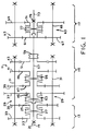
- FIG. 1 is a schematic illustration of a compound change gear transmission of the type with which the present invention may be utilized.
- FIG. 2 is a schematic illustration of the shift pattern for the transmission of FIG. 1.
- FIG. 3 is a somewhat schematic top view of the shift bar housing assembly of the transmission of the present invention.
- FIG. 4 is a fragmentary, perspective view of a shift rail illustrating one aspect of the present invention.
- compound transmission is used to designate a change speed or change gear transmission having a main transmission section and an auxiliary transmission section connected in series, whereby the selected gear reduction in the main transmission section may be compounded by further selected gear reduction in the auxiliary transmission section.
- upshift shall mean the shifting from a lower speed gear ratio to a higher speed gear ratio
- downshift shall mean the shifting from a higher speed gear ratio to a lower speed gear ratio.
- the transmission 11 is a "(2)x(4)x(2)" type sixteen-speed transmission having a two-speed splitter section 13, a four forward-speed main section 15 and a two-speed range section 17, all connected in series.
- the gearing of the transmission 11 may be either of the spur-type or of the helical-type.
- Input shaft 19 is supported within the transmission housing forward wall (not shown) by means of a bearing 21, and is surrounded by two input gears 23 and 25, a selected one of which is clutched to the input shaft by a synchronized clutch 27 to provide a two-speed splitter input section.
- Front counter shaft assemblies 29 each include a counter shaft 31 carrying counter shaft gears 33, 35, 37, 39, 41, and 43. Gears 33 and 35 are constantly meshed with the input gears 23 and 25, respectively. In the main section 15, the gears 37, 39, 41, and 43 are constantly meshed with main shaft gears 45, 47, 49 and a reverse idler (not shown) is meshed with a reverse main shaft gear 51. Double acting synchronized clutches 53 and 55 are provided on a main shaft 57 to clutch the main shaft 57 to a selected one of the input shaft 19 or main shaft gears 45, 47 or 49. A non-synchronized clutch 59 is used to clutch the reverse main shaft gear 51 to the main shaft 57.
- auxiliary section counter shaft assemblies 63 each include an auxiliary section counter shaft 65 carrying two auxiliary section counter shaft gears 67 and 69.
- Gear 67 is constantly meshed with the auxiliary input gear 61
- gear 69 is constantly meshed with an output gear 71 surrounding an output shaft 73.
- the output shaft 73 is supported in the housing rear end wall (not shown) by a bearing 75.
- a two-position synchronized range clutch 77 is carried by the output shaft 73 and is utilized to clutch either the output gear 71 or the main shaft 57 to the output shaft 73.
- the shift pattern for shifting the transmission 11 is schematically illustrated in FIG. 2 in which divisions in the vertical direction (arrow labelled R illustrate shifts of the range section 17, while divisions in the horizontal direction (arrow labelled S ) illustrate shifts of the splitter section 13.
- R illustrate shifts of the vertical direction
- S illustrate shifts of the horizontal direction
- the present invention is not limited to any particular shift pattern, except to the extent specifically recited in the appended claims.
- the splitter section 13 is located forwardly of the main section 15, but it should be understood by those skilled in the art that the invention is not so limited.
- the splitter section could be combined with the range section 17 in a single, auxiliary section disposed rearwardly of the main section 15.
- the present invention could be utilized in a transmission having no splitter section at all, but only the main section 15 and the range section 17.
- the shift control unit includes a shift bar housing assembly 81 which is mountable on the upper opening of the transmission 11.
- the shift bar housing 81 supports a first shift bar (also called a "shift rail") 83 and a second shift bar or shift rail 85 for independent axial movement therein.
- Each of the shift rails 83 and 85 carries a shift fork (not shown herein) for axial movement therewith.
- the construction and operation of the shift rail 83 in the subject embodiment is preferably as is set forth in U.S. Patent No. 4,920,815, assigned to the assignee of the present invention and incorporated herein by reference.
- the shift rail 83 is moveable both axially (from right to left and left to right in FIG. 3) and rotationally about an axis 87 of the shift rail 83.
- the function of the shift rail 83 is to engage the main shaft gears 45, 47, 49 and the reverse main shaft gear 51 to the main shaft 57.
- the second shift rail 85 moves only axially, and is operatively associated with a shift rail extension 89 which extends axially out of the shift bar housing 81 and into the range section 17, for operable engagement with the range clutch 77, to select between low range and high range, as was described previously in connection with FIG. 2.
- An interlock mechanism indicated generally at 91 is included to prevent simultaneous movement of the shift rails 83 and 85 from the neutral, centered positions illustrated in FIG. 3, although, in accordance with the present invention, there will be one exception to the general rule that both shift rails can't be displaced from their neutral position at the same time.
- the shift bar housing 81 is provided with an opening 93 for receipt of a shift finger (not shown) carried by either a standard direct control shift lever or a cross shaft of a remote control mechanism, as is well known to those skilled in the art.
- the shift rail 83 carries a bushing member 95 fixed for rotational and axial movement therewith and defining a generally upwardly facing socket 97 adapted to receive the lower end of the shift finger, to define a ball and socket type connection therewith.
- the shift rail 83 includes, toward its forward end (left end in FIG. 3), an annular groove 99.
- the shift rail 85 includes, toward its forward end, an annular groove 101 (shown only in FIG. 3).
- an interlock pin 103 Disposed between the shift rails 83 and 85 is an interlock pin 103, the opposite axial ends of which are preferably beveled or frusto-conical.
- the shift rail 83 also defines an axial slot 105 which, in the subject embodiment, opens into the annular groove 99 for reasons which will be described subsequently.
- the interlock mechanism 91 will be understood by reference to above-incorporated U.S. Patent Numbers 4,445,393 and 4,944,197. Briefly, with the shift rail 83 in its neutral position shown in FIG. 3, the range section shift rail 85 may be moved axially, in either direction from its neutral position shown in FIG. 3. When the shift rail 85 is moved axially, the upper end of the interlock pin 103 is no longer aligned with the annular groove 101, but instead, now engages one of the full diameters of the shift rail 85.
- the axial slot 105 has been provided. As was described previously, actuation of the shift rail 83 to select the various gear ratios in the main section 15 is achieved by moving the shift rail 83 axially and/or rotationally.
- the position of the axial slot 105 is on that portion of the shift rail 83 which is disposed adjacent the lower end of the interlock pin 103 whenever the shift rail 83 is moved to engage the clutch 59, and select reverse gear.
- the shift rail 83 can then be moved by the operator from the reverse gear position to the first gear position, in preparation for progressing through the normal shift pattern.
- the present invention has been described in connection with a main section 15 having a single shift rail 83, it should be understood by those skilled in the art that the invention is not so limited.
- a main section with a plurality of parallel shift rails and an interlock arrangement between those shift rails and the shift rail associated with the auxiliary section.
- the shift rail for the main section which is used to select reverse gear would be provided with a notch or a recess or a slot or some other suitable structure disposed adjacent the interlock pin, such that the interlock pin would engage the recess or axial slot, etc. whenever that particular rail selects reverse gear.
Landscapes
- Engineering & Computer Science (AREA)
- General Engineering & Computer Science (AREA)
- Mechanical Engineering (AREA)
- Gear-Shifting Mechanisms (AREA)
- Structure Of Transmissions (AREA)
- Pallets (AREA)
- Food-Manufacturing Devices (AREA)
- Switch Cases, Indication, And Locking (AREA)
- Gear Transmission (AREA)
- Manufacture Of Alloys Or Alloy Compounds (AREA)
Applications Claiming Priority (2)
| Application Number | Priority Date | Filing Date | Title |
|---|---|---|---|
| US355358 | 1994-12-13 | ||
| US08/355,358 US5546825A (en) | 1994-12-13 | 1994-12-13 | Change gear transmission and shift rod interlock therefor |
Publications (3)
| Publication Number | Publication Date |
|---|---|
| EP0722059A2 true EP0722059A2 (de) | 1996-07-17 |
| EP0722059A3 EP0722059A3 (de) | 1998-01-07 |
| EP0722059B1 EP0722059B1 (de) | 1999-09-08 |
Family
ID=23397162
Family Applications (1)
| Application Number | Title | Priority Date | Filing Date |
|---|---|---|---|
| EP95308469A Expired - Lifetime EP0722059B1 (de) | 1994-12-13 | 1995-11-27 | Verriegelung mit Nut zu deren Deaktivierung |
Country Status (10)
| Country | Link |
|---|---|
| US (1) | US5546825A (de) |
| EP (1) | EP0722059B1 (de) |
| JP (1) | JP3598477B2 (de) |
| KR (1) | KR100274964B1 (de) |
| CN (1) | CN1082154C (de) |
| AT (1) | ATE184381T1 (de) |
| BR (1) | BR9505411A (de) |
| CA (1) | CA2164747C (de) |
| DE (1) | DE69512013T2 (de) |
| ES (1) | ES2137461T3 (de) |
Cited By (1)
| Publication number | Priority date | Publication date | Assignee | Title |
|---|---|---|---|---|
| WO2007062747A1 (de) * | 2005-11-30 | 2007-06-07 | Zf Friedrichshafen Ag | Vorrichtung zur kombinierten rastung und verriegelung einer schaltvorrichtung |
Families Citing this family (5)
| Publication number | Priority date | Publication date | Assignee | Title |
|---|---|---|---|---|
| US6966237B2 (en) * | 2001-04-02 | 2005-11-22 | Zf Meritor, Llc | First gear/reverse gate indicator switch |
| JP4450634B2 (ja) * | 2004-01-14 | 2010-04-14 | 株式会社東海理化電機製作所 | シフトレバー装置 |
| DE102005051377A1 (de) * | 2005-10-27 | 2007-05-03 | Zf Friedrichshafen Ag | Getriebeschaltvorrichtung mit variabler Gassensperrkraft |
| DE102011017663A1 (de) * | 2011-04-28 | 2012-10-31 | Zf Friedrichshafen Ag | Schalteinrichtung |
| US10495216B2 (en) | 2017-01-26 | 2019-12-03 | Kongsberg Automotive As | Interrocker assembly |
Citations (4)
| Publication number | Priority date | Publication date | Assignee | Title |
|---|---|---|---|---|
| US4445393A (en) | 1982-01-18 | 1984-05-01 | Eaton Corporation | Fluid actuated shift bar housing assembly |
| US4754665A (en) | 1986-02-05 | 1988-07-05 | Eaton Corporation | Auxiliary transmission section |
| US4920815A (en) | 1989-04-24 | 1990-05-01 | Eaton Corporation | Single shaft shifting mechanism |
| US4944197A (en) | 1989-06-07 | 1990-07-31 | Eaton Corporation | Resilient range interlock |
Family Cites Families (11)
| Publication number | Priority date | Publication date | Assignee | Title |
|---|---|---|---|---|
| US2317761A (en) * | 1940-05-31 | 1943-04-27 | Borg Warner | Transmission |
| US2438691A (en) * | 1944-09-11 | 1948-03-30 | Borg Warner | Transmission control mechanism |
| CH247583A (de) * | 1945-06-04 | 1947-03-15 | Hanvag Ges Fuer Tech Vervollko | Geschwindigkeitswechselgetriebe. |
| US2512036A (en) * | 1947-05-22 | 1950-06-20 | Borg Warner | Transmission |
| US3354741A (en) * | 1965-06-14 | 1967-11-28 | Int Harvester Co | Single lever control for dual rail transmission |
| US3584517A (en) * | 1969-05-29 | 1971-06-15 | Case Co J I | Mechanism for interconnecting parts |
| DE2713784C2 (de) * | 1977-03-29 | 1979-02-01 | Zahnradfabrik Friedrichshafen Ag, 7990 Friedrichshafen | Schalteinrichtung mit einer Sperreinrichtung für ein mehrgängiges Wendegetriebe |
| GB8809945D0 (en) * | 1988-04-27 | 1988-06-02 | Eaton Corp | Pneumatic control system |
| US4974468A (en) * | 1989-02-16 | 1990-12-04 | Eaton Corporation | Compound transmission and shift control therefor |
| US5216931A (en) * | 1992-01-23 | 1993-06-08 | Eaton Corporation | Interlock mechanism for range section slave valve |
| US5284065A (en) * | 1992-09-18 | 1994-02-08 | Dana Corporation | Removable overdrive lockout |
-
1994
- 1994-12-13 US US08/355,358 patent/US5546825A/en not_active Expired - Fee Related
-
1995
- 1995-11-27 ES ES95308469T patent/ES2137461T3/es not_active Expired - Lifetime
- 1995-11-27 EP EP95308469A patent/EP0722059B1/de not_active Expired - Lifetime
- 1995-11-27 AT AT95308469T patent/ATE184381T1/de not_active IP Right Cessation
- 1995-11-27 DE DE69512013T patent/DE69512013T2/de not_active Expired - Fee Related
- 1995-12-08 CA CA002164747A patent/CA2164747C/en not_active Expired - Fee Related
- 1995-12-12 JP JP34648295A patent/JP3598477B2/ja not_active Expired - Fee Related
- 1995-12-13 KR KR1019950049293A patent/KR100274964B1/ko not_active IP Right Cessation
- 1995-12-13 BR BR9505411A patent/BR9505411A/pt not_active IP Right Cessation
- 1995-12-13 CN CN95121637A patent/CN1082154C/zh not_active Expired - Fee Related
Patent Citations (4)
| Publication number | Priority date | Publication date | Assignee | Title |
|---|---|---|---|---|
| US4445393A (en) | 1982-01-18 | 1984-05-01 | Eaton Corporation | Fluid actuated shift bar housing assembly |
| US4754665A (en) | 1986-02-05 | 1988-07-05 | Eaton Corporation | Auxiliary transmission section |
| US4920815A (en) | 1989-04-24 | 1990-05-01 | Eaton Corporation | Single shaft shifting mechanism |
| US4944197A (en) | 1989-06-07 | 1990-07-31 | Eaton Corporation | Resilient range interlock |
Cited By (1)
| Publication number | Priority date | Publication date | Assignee | Title |
|---|---|---|---|---|
| WO2007062747A1 (de) * | 2005-11-30 | 2007-06-07 | Zf Friedrichshafen Ag | Vorrichtung zur kombinierten rastung und verriegelung einer schaltvorrichtung |
Also Published As
| Publication number | Publication date |
|---|---|
| EP0722059A3 (de) | 1998-01-07 |
| MX9505214A (es) | 1998-05-31 |
| JP3598477B2 (ja) | 2004-12-08 |
| DE69512013T2 (de) | 2000-05-25 |
| CA2164747A1 (en) | 1996-06-14 |
| DE69512013D1 (de) | 1999-10-14 |
| BR9505411A (pt) | 1997-10-28 |
| KR960023939A (ko) | 1996-07-20 |
| ATE184381T1 (de) | 1999-09-15 |
| JPH08247284A (ja) | 1996-09-24 |
| US5546825A (en) | 1996-08-20 |
| CN1082154C (zh) | 2002-04-03 |
| ES2137461T3 (es) | 1999-12-16 |
| KR100274964B1 (ko) | 2000-12-15 |
| CA2164747C (en) | 2000-10-31 |
| CN1131244A (zh) | 1996-09-18 |
| EP0722059B1 (de) | 1999-09-08 |
Similar Documents
| Publication | Publication Date | Title |
|---|---|---|
| EP0383493B1 (de) | Verbundgetriebe und zugehörige Schaltsteuerung | |
| EP0401514B1 (de) | Nachgiebige Schaltbereichsverriegelung | |
| US5000060A (en) | Compound transmission and shift control therefor | |
| EP0601741B1 (de) | Ruckschaltungs-Schutzvorrichtung | |
| EP0202800B1 (de) | Leistungssynchronisiereinrichtung | |
| US5651292A (en) | Splitter shift mechanism and control | |
| US4966048A (en) | Manual transmission and shift control therefor | |
| US5737969A (en) | Single shaft shifting mechanism | |
| EP0595496A2 (de) | Halbautomatische Schaltdurchführung | |
| US6220108B1 (en) | Manually shifted transmission with enhanced automatic range shift | |
| US5492209A (en) | Shift control mechanism for a multi-speed countershaft transmission | |
| EP0618382A1 (de) | Zusatzgetriebeeinheit | |
| US6257082B1 (en) | Auxiliary section control for manual transmission | |
| US5546825A (en) | Change gear transmission and shift rod interlock therefor | |
| US6520040B2 (en) | Range control for manual transmission | |
| EP0694716B1 (de) | Schaltmechanismus für ein Mehrganggetriebe der Vorgelegebauart | |
| EP0737828A1 (de) | Fahrzeuggetriebe | |
| MXPA95005214A (en) | Entering with display slot | |
| US5394763A (en) | Auxiliary transmission section | |
| EP0767328A1 (de) | Getriebe | |
| GB2361036A (en) | Compound transmission with automatic range shift if incorrect gear shift is selected |
Legal Events
| Date | Code | Title | Description |
|---|---|---|---|
| PUAI | Public reference made under article 153(3) epc to a published international application that has entered the european phase |
Free format text: ORIGINAL CODE: 0009012 |
|
| AK | Designated contracting states |
Kind code of ref document: A2 Designated state(s): AT DE ES FR GB IT NL SE |
|
| PUAL | Search report despatched |
Free format text: ORIGINAL CODE: 0009013 |
|
| AK | Designated contracting states |
Kind code of ref document: A3 Designated state(s): AT DE ES FR GB IT NL SE |
|
| 17P | Request for examination filed |
Effective date: 19980612 |
|
| GRAG | Despatch of communication of intention to grant |
Free format text: ORIGINAL CODE: EPIDOS AGRA |
|
| 17Q | First examination report despatched |
Effective date: 19981125 |
|
| GRAG | Despatch of communication of intention to grant |
Free format text: ORIGINAL CODE: EPIDOS AGRA |
|
| GRAH | Despatch of communication of intention to grant a patent |
Free format text: ORIGINAL CODE: EPIDOS IGRA |
|
| GRAH | Despatch of communication of intention to grant a patent |
Free format text: ORIGINAL CODE: EPIDOS IGRA |
|
| GRAA | (expected) grant |
Free format text: ORIGINAL CODE: 0009210 |
|
| AK | Designated contracting states |
Kind code of ref document: B1 Designated state(s): AT DE ES FR GB IT NL SE |
|
| REF | Corresponds to: |
Ref document number: 184381 Country of ref document: AT Date of ref document: 19990915 Kind code of ref document: T |
|
| ITF | It: translation for a ep patent filed |
Owner name: STUDIO GLP S.R.L. |
|
| REF | Corresponds to: |
Ref document number: 69512013 Country of ref document: DE Date of ref document: 19991014 |
|
| REG | Reference to a national code |
Ref country code: ES Ref legal event code: FG2A Ref document number: 2137461 Country of ref document: ES Kind code of ref document: T3 |
|
| ET | Fr: translation filed | ||
| PLBE | No opposition filed within time limit |
Free format text: ORIGINAL CODE: 0009261 |
|
| STAA | Information on the status of an ep patent application or granted ep patent |
Free format text: STATUS: NO OPPOSITION FILED WITHIN TIME LIMIT |
|
| 26N | No opposition filed | ||
| REG | Reference to a national code |
Ref country code: GB Ref legal event code: IF02 |
|
| PGFP | Annual fee paid to national office [announced via postgrant information from national office to epo] |
Ref country code: NL Payment date: 20081015 Year of fee payment: 14 |
|
| PGFP | Annual fee paid to national office [announced via postgrant information from national office to epo] |
Ref country code: ES Payment date: 20081125 Year of fee payment: 14 Ref country code: AT Payment date: 20081008 Year of fee payment: 14 |
|
| PGFP | Annual fee paid to national office [announced via postgrant information from national office to epo] |
Ref country code: SE Payment date: 20081107 Year of fee payment: 14 |
|
| PGFP | Annual fee paid to national office [announced via postgrant information from national office to epo] |
Ref country code: FR Payment date: 20081106 Year of fee payment: 14 |
|
| PGFP | Annual fee paid to national office [announced via postgrant information from national office to epo] |
Ref country code: DE Payment date: 20081128 Year of fee payment: 14 |
|
| PGFP | Annual fee paid to national office [announced via postgrant information from national office to epo] |
Ref country code: GB Payment date: 20081008 Year of fee payment: 14 |
|
| REG | Reference to a national code |
Ref country code: NL Ref legal event code: V1 Effective date: 20100601 |
|
| EUG | Se: european patent has lapsed | ||
| GBPC | Gb: european patent ceased through non-payment of renewal fee |
Effective date: 20091127 |
|
| REG | Reference to a national code |
Ref country code: FR Ref legal event code: ST Effective date: 20100730 |
|
| PG25 | Lapsed in a contracting state [announced via postgrant information from national office to epo] |
Ref country code: AT Free format text: LAPSE BECAUSE OF NON-PAYMENT OF DUE FEES Effective date: 20091127 |
|
| PG25 | Lapsed in a contracting state [announced via postgrant information from national office to epo] |
Ref country code: NL Free format text: LAPSE BECAUSE OF NON-PAYMENT OF DUE FEES Effective date: 20100601 Ref country code: FR Free format text: LAPSE BECAUSE OF NON-PAYMENT OF DUE FEES Effective date: 20091130 |
|
| PG25 | Lapsed in a contracting state [announced via postgrant information from national office to epo] |
Ref country code: DE Free format text: LAPSE BECAUSE OF NON-PAYMENT OF DUE FEES Effective date: 20100601 |
|
| PG25 | Lapsed in a contracting state [announced via postgrant information from national office to epo] |
Ref country code: GB Free format text: LAPSE BECAUSE OF NON-PAYMENT OF DUE FEES Effective date: 20091127 |
|
| REG | Reference to a national code |
Ref country code: ES Ref legal event code: FD2A Effective date: 20110325 |
|
| PG25 | Lapsed in a contracting state [announced via postgrant information from national office to epo] |
Ref country code: SE Free format text: LAPSE BECAUSE OF NON-PAYMENT OF DUE FEES Effective date: 20091128 |
|
| PG25 | Lapsed in a contracting state [announced via postgrant information from national office to epo] |
Ref country code: ES Free format text: LAPSE BECAUSE OF NON-PAYMENT OF DUE FEES Effective date: 20110314 |
|
| PG25 | Lapsed in a contracting state [announced via postgrant information from national office to epo] |
Ref country code: ES Free format text: LAPSE BECAUSE OF NON-PAYMENT OF DUE FEES Effective date: 20091128 |
|
| PGFP | Annual fee paid to national office [announced via postgrant information from national office to epo] |
Ref country code: IT Payment date: 20141117 Year of fee payment: 20 |