EP0383493B1 - Verbundgetriebe und zugehörige Schaltsteuerung - Google Patents
Verbundgetriebe und zugehörige Schaltsteuerung Download PDFInfo
- Publication number
- EP0383493B1 EP0383493B1 EP90301387A EP90301387A EP0383493B1 EP 0383493 B1 EP0383493 B1 EP 0383493B1 EP 90301387 A EP90301387 A EP 90301387A EP 90301387 A EP90301387 A EP 90301387A EP 0383493 B1 EP0383493 B1 EP 0383493B1
- Authority
- EP
- European Patent Office
- Prior art keywords
- shift
- control shaft
- range
- assembly
- axially
- Prior art date
- Legal status (The legal status is an assumption and is not a legal conclusion. Google has not performed a legal analysis and makes no representation as to the accuracy of the status listed.)
- Expired - Lifetime
Links
Images


Classifications
-
- F—MECHANICAL ENGINEERING; LIGHTING; HEATING; WEAPONS; BLASTING
- F16—ENGINEERING ELEMENTS AND UNITS; GENERAL MEASURES FOR PRODUCING AND MAINTAINING EFFECTIVE FUNCTIONING OF MACHINES OR INSTALLATIONS; THERMAL INSULATION IN GENERAL
- F16H—GEARING
- F16H3/00—Toothed gearings for conveying rotary motion with variable gear ratio or for reversing rotary motion
- F16H3/02—Toothed gearings for conveying rotary motion with variable gear ratio or for reversing rotary motion without gears having orbital motion
- F16H3/42—Toothed gearings for conveying rotary motion with variable gear ratio or for reversing rotary motion without gears having orbital motion with gears having teeth formed or arranged for obtaining multiple gear ratios, e.g. nearly infinitely variable
-
- F—MECHANICAL ENGINEERING; LIGHTING; HEATING; WEAPONS; BLASTING
- F16—ENGINEERING ELEMENTS AND UNITS; GENERAL MEASURES FOR PRODUCING AND MAINTAINING EFFECTIVE FUNCTIONING OF MACHINES OR INSTALLATIONS; THERMAL INSULATION IN GENERAL
- F16H—GEARING
- F16H63/00—Control outputs from the control unit to change-speed- or reversing-gearings for conveying rotary motion or to other devices than the final output mechanism
- F16H63/40—Control outputs from the control unit to change-speed- or reversing-gearings for conveying rotary motion or to other devices than the final output mechanism comprising signals other than signals for actuating the final output mechanisms
- F16H63/44—Signals to the control unit of auxiliary gearing
-
- F—MECHANICAL ENGINEERING; LIGHTING; HEATING; WEAPONS; BLASTING
- F16—ENGINEERING ELEMENTS AND UNITS; GENERAL MEASURES FOR PRODUCING AND MAINTAINING EFFECTIVE FUNCTIONING OF MACHINES OR INSTALLATIONS; THERMAL INSULATION IN GENERAL
- F16H—GEARING
- F16H63/00—Control outputs from the control unit to change-speed- or reversing-gearings for conveying rotary motion or to other devices than the final output mechanism
- F16H63/02—Final output mechanisms therefor; Actuating means for the final output mechanisms
- F16H63/30—Constructional features of the final output mechanisms
- F16H63/34—Locking or disabling mechanisms
-
- F—MECHANICAL ENGINEERING; LIGHTING; HEATING; WEAPONS; BLASTING
- F16—ENGINEERING ELEMENTS AND UNITS; GENERAL MEASURES FOR PRODUCING AND MAINTAINING EFFECTIVE FUNCTIONING OF MACHINES OR INSTALLATIONS; THERMAL INSULATION IN GENERAL
- F16H—GEARING
- F16H61/00—Control functions within control units of change-speed- or reversing-gearings for conveying rotary motion ; Control of exclusively fluid gearing, friction gearing, gearings with endless flexible members or other particular types of gearing
- F16H61/70—Control functions within control units of change-speed- or reversing-gearings for conveying rotary motion ; Control of exclusively fluid gearing, friction gearing, gearings with endless flexible members or other particular types of gearing specially adapted for change-speed gearing in group arrangement, i.e. with separate change-speed gear trains arranged in series, e.g. range or overdrive-type gearing arrangements
-
- F—MECHANICAL ENGINEERING; LIGHTING; HEATING; WEAPONS; BLASTING
- F16—ENGINEERING ELEMENTS AND UNITS; GENERAL MEASURES FOR PRODUCING AND MAINTAINING EFFECTIVE FUNCTIONING OF MACHINES OR INSTALLATIONS; THERMAL INSULATION IN GENERAL
- F16H—GEARING
- F16H63/00—Control outputs from the control unit to change-speed- or reversing-gearings for conveying rotary motion or to other devices than the final output mechanism
- F16H63/02—Final output mechanisms therefor; Actuating means for the final output mechanisms
- F16H63/30—Constructional features of the final output mechanisms
- F16H63/3023—Constructional features of the final output mechanisms the final output mechanisms comprising elements moved by fluid pressure
-
- Y—GENERAL TAGGING OF NEW TECHNOLOGICAL DEVELOPMENTS; GENERAL TAGGING OF CROSS-SECTIONAL TECHNOLOGIES SPANNING OVER SEVERAL SECTIONS OF THE IPC; TECHNICAL SUBJECTS COVERED BY FORMER USPC CROSS-REFERENCE ART COLLECTIONS [XRACs] AND DIGESTS
- Y10—TECHNICAL SUBJECTS COVERED BY FORMER USPC
- Y10T—TECHNICAL SUBJECTS COVERED BY FORMER US CLASSIFICATION
- Y10T74/00—Machine element or mechanism
- Y10T74/19—Gearing
- Y10T74/19167—In series plural interchangeably locked nonplanetary units
-
- Y—GENERAL TAGGING OF NEW TECHNOLOGICAL DEVELOPMENTS; GENERAL TAGGING OF CROSS-SECTIONAL TECHNOLOGIES SPANNING OVER SEVERAL SECTIONS OF THE IPC; TECHNICAL SUBJECTS COVERED BY FORMER USPC CROSS-REFERENCE ART COLLECTIONS [XRACs] AND DIGESTS
- Y10—TECHNICAL SUBJECTS COVERED BY FORMER USPC
- Y10T—TECHNICAL SUBJECTS COVERED BY FORMER US CLASSIFICATION
- Y10T74/00—Machine element or mechanism
- Y10T74/20—Control lever and linkage systems
- Y10T74/20012—Multiple controlled elements
- Y10T74/20018—Transmission control
- Y10T74/20073—Control of plural mechanisms [e.g., control of transmission and control of 4 - wheel drive]
Definitions
- This invention relates to a compound transmission comprising a multispeed main transmission section connected in series with a multispeed auxiliary transmission section, preferably of the combined splitter and range type, and to a combined shift control device therefor.
- this invention relates to a shift control unit for a manually shifted compound transmission comprising a shift finger operated shift bar housing assembly for selecting mainsection gear ratios, at least one of said mainsection ratios selectable in two different shift bar housing assembly positions, and a control device or switch for sensing positioning of the shift bar housing assembly in said two positions and for automatically shifting a two-speed range portion of said auxiliary transmission (or multispeed axle or multispeed transfer case) accordingly.
- Compound transmission systems comprising manually shifted multispeed main transmission sections connected in series with one or more multispeed auxiliary drivetrain sections, usually of the range, splitter or combined range/splitter type are well known in the prior art.
- the auxiliary sections are usually input and/or output auxiliary transmission sections but may also be multispeed drive axles, transfer cases or the like. Examples of such compound systems may be seen by reference to U.S. Patent Nos. US-A-4 754 665; US-A-3 648 546; US-A-3 799 002; US-A-4 455 883 and US-A-4 527 447.
- Control devices or assemblies for controlling the shifting of both the main transmission and the auxiliary drive train unit by requiring the vehicle operator to manipulate only a shift lever along an extended H type shift pattern are also known in the prior art as may be seen by reference to U.S. Patent Nos. US-A-3 429 202; US-A-4 455 883; US-A-4 561 325 and US-A-4 633 725.
- a compound transmission comprising a multiple speed main transmission section connected in series with a multiple speed auxiliary section, preferably including at least two speed range gearing, one of which range ratios is utilized with only one ratio (or two ratios if controlled by the same shift fork) of the mainsection.
- the shift control for the transmission includes a shift bar housing actuated by a standard shift lever or cross-shaft shift finger and defines two distinct positions for moving the shift bar and shift fork associated with the main section ratio or ratios compounded by the two-speed auxiliary range ratio.
- Movement of the shift finger actuated shift bar housing between the two distinct positions associated with movement of the one shift fork is sensed internally of the shift bar housing to actuate devices mounted at the transmission for shifting of the auxiliary two-speed range section.
- a resilient interlock is actuated during auxiliary section range ratio shift transients to inhibit but not prohibit shifting of the mainsection until the range shift in the auxiliary section is completed. The inhibition to shifting can thus be overcome by the operator.
- a manually shifted compound transmission embodiment having a two-speed auxiliary range section compounding only a single or a pair of mainsection ratios
- a shift control unit wherein the compounded mainsection ratio or pair of ratios may be selected in either one of two distinct shift bar housing positions, preferably corresponding to adjacent parallel legs of an extended H-type shift pattern, shifting between the two parallel legs automatically resulting in shifting of the two-speed auxiliary to the appropriate ratio.
- the control unit is activated by a standard shift finger and is thus suitable for use in either a direct or remote control transmission system and requires no special modification of the shift lever, nor sensors or wiring or air controls at the shift lever location, for shifting of the two-speed auxiliary range ratio.
- compound transmission is used to designate a change speed or change gear transmission having a main transmission section and an auxiliary drive train unit, such as an auxiliary transmission section, connected in series whereby the selected gear reduction in the main transmission section may be compounded by further selected gear reduction in the auxiliary transmission section. It is understood, that while the preferred embodiment of the present invention utilizes an auxiliary transmission section connected in series with the main transmission section, the invention is equally applicable to simple transmissions connected in series with shiftable multispeed devices such as multispeed transfer cases and/or multispeed rear drive axle systems.
- upshift shall mean the shifting from a lower speed gear ratio to a higher speed gear ratio and the term “downshift” as used herein shall mean the shifting from a higher speed gear ratio to a lower speed gear ratio.
- low speed gear or “low gear” as used herein shall designate a gear utilized for relatively lower forward speed operation in a transmission, i.e., a set of gears having a higher ratio of reduction of output shaft speed relative to the speed of the input shaft.
- Transmission 10 comprises a main transmission section 12 connected in series with an auxiliary transmission section 14 having both range and splitter type gearing.
- transmission 10 is housed within a single multipiece housing 16 and includes an input shaft 18 driven by a prime mover such as a diesel engine (not shown) through a selectively disengaged, normally engaged, friction master clutch (not shown).
- a prime mover such as a diesel engine (not shown) through a selectively disengaged, normally engaged, friction master clutch (not shown).
- the input shaft 18 carries an input gear 20 for driving at least one countershaft assembly 22.
- input gear 20 simultaneously drives a plurality of substantially identical mainsection countershaft assemblies at substantially identical rotational speeds.
- Each of the mainsection countershaft assemblies comprises a mainsection countershaft 24 supported by bearings 26 and 28 in housing 16 and is provided with mainsection countershaft gears 30, 32, 34, 36 and 38 fixed thereto.
- a plurality of mainsection drive or mainshaft gears 40, 42 and 44 surround the transmission mainshaft 46 and are selectively clutchable, one at a time, to the mainshaft 46 for rotation therewith by sliding clutch collars 48 and 50 as is well known in the art.
- Clutch collar 48 may also be utilized to clutch input gear 20 to the mainshaft 46 to provide a direct drive relationship between the input shaft 18 and the mainshaft 46.
- each of the mainsection mainshaft gears encircles the mainshaft 46 and is in continuous meshing engagement with and is floatingly supported by the associated countershaft gear groups, which mounting means and special advantages resulting therefrom are explained in greater detail in above-mentioned United States Patent Nos.
- clutch collars 48 and 50 are axially positioned by means of shift forks or yokes 52 and 54, respectively, associated with a shift bar housing assembly 56 to be described in greater detail below.
- Clutch collars 48 and 50 are, in the preferred embodiment, of the well known non-synchronized double acting jaw clutch type.
- Main section mainshaft gear 44 is the reverse gear and is in continuous meshing engagement with countershaft gears 38 by means of conventional intermediate idler gears 57 (see Fig 1A).
- Main section countershaft gear 32 is provided for powering power takeoff devices and the like.
- Jaw clutches 48 and 50 are three-position clutches in that they may be positioned in a centered axially nondisplaced , nonengaged position as illustrated or in a fully rightwardly engaged or fully leftwardly engaged position.
- Auxiliary transmission section 14 is connected in series with main transmission section 12 and is of the three-layer, four speed combined splitter/range type as illustrated in above-mentioned United States Patent No. US-A-4 754 665.
- Mainshaft 46 extends into the auxiliary section 14 and is journalled in the inward end of the output shaft 58 which extends from the rearward end of the transmission.
- Auxiliary transmission section 14 includes, in the preferred embodiment thereof, a plurality of substantially identical auxiliary countershaft assemblies 60 (see Figure 1A) each comprising an auxiliary countershaft 62 supported by bearings 64 and 66 in housing 16 and carrying three auxiliary section countershaft gears 68, 70 and 72 fixed for rotation therewith.
- Auxiliary countershaft gears 68 are constantly meshed with and support auxiliary section splitter gear 74.
- Auxiliary countershaft gears 70 are constantly meshed with and support auxiliary section splitter/range gear 76 which surrounds the output shaft 58 at the end thereof adjacent the coaxial inner end of mainshaft 46.
- Auxiliary section countershaft gears 72 constantly mesh with and support auxiliary section range gear 78 which surrounds the output shaft 58.
- auxiliary section countershaft gears 68 and splitter gear 74 define a first gear layer
- auxiliary section countershaft gears 70 and splitter/range gear 76 define a second gear layer
- auxiliary section countershaft gears 72 and range gear 78 define a third layer, or gear group, of the combined splitter and range type auxiliary transmission section 14.
- a sliding two-position jaw clutch collar 80 is utilized to selectively couple either the splitter gear 74 or the splitter/range gear 76 to the mainshaft 46 while a two-position synchronized clutch assembly 82 utilized to selectively couple the splitter/range gear 76 or the range gear 78 to the output shaft 58.
- the structure and function of double-acting jaw clutch collar 80 is substantially identical to the structure and function of the sliding clutch collars 48 and 50 utilized in the main transmission section 12 and the function of double-acting synchronized clutch assembly 82 is substantially identical to the structure and function of prior art double-acting synchronized clutch assembly, examples of which may be seen by reference to United States Patent Nos. US-A-4 462 489; US-A-4 125 179 and US-A-2 667 955.
- the synchronized clutch assembly 82 illustrated is of the pin-type described in above-mentioned U.S. Patent No. US-A-4 462 489.
- the splitter jaw clutch 80 is a two-position clutch assembly which may be selectively positioned in the rightwardmost or leftwardmost positions for engaging either gear 76 or gear 74, respectively, to the mainshaft 46.
- Splitter jaw clutch 80 is axially positioned by means of a shift fork 84 controlled by a two-position piston actuator 86 which is operable by a driver selection switch such as a button or the like on the shift knob (not shown) as is known in the prior art.
- Two-position synchronized clutch assembly 82 is also a two-position clutch which may be selectively positioned in either the rightwardmost or leftwardmost positions thereof for selectively clutching either gear 78 or 76, respectively, to output shaft 58.
- Clutch assembly 82 is positioned by means of a shift fork 88 operated by means of a two-position piston device 90, the actuation and control of which will be described in greater detail below.
- auxiliary transmission section 14 is a three layer auxiliary section of the combined range and splitter type providing four selectable speeds or drive ratios between the input (mainshaft 46) and output (output shaft 58) thereof.
- the mainsection 12 provides a reverse and three potentially selectable forward speeds.
- one of the selectable mainsection forward gear ratios, the low speed gear ratios associated with mainshaft gear 42, is not utilized in the high range.
- transmission 10 is properly designated as a "(2+1) X (2X2)" type transmission providing nine or ten selectable forward speeds, depending upon the desirability and practicality of splitting the low gear ratio.
- clutch 82 the range clutch
- clutch collar 80 the splitter clutch
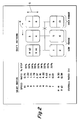
- the shift pattern for shifting transmission 10 is schematically illustrated in Figure 2. Divisions in the vertical direction at each gear lever position signify splitter shifts while movement in the horizontal direction from the three/four and five/six leg of the H pattern to the seven/eight and nine/ten leg of the H pattern signifies a shift from the low range to the high range of the transmission.
- splitter shifting is accomplished in the usual manner by means of a vehicle operator actuated splitter button or the like, usually a button located at the shift lever knob while operation of the range clutch shifting assembly is an automatic response to movement of the gear shift lever between the central and rightwardmost legs of the shift pattern as illustrated in Figure 2 and will be described in greater detail below.
- Range shift devices of this general type are known in the prior art and may be seen by reference to above-mentioned United States Patent Nos. US-A-3 429 202; US-A-4 455 883; US-A-4 561 325 and US-A-4 633 725.
- N the number of mainsection ratio steps occurring in both ranges
- gearing to approximate these ratios is selected.
- the splitter steps are about 33.3% while the range step is about 316% which is generally suitable for a "2+1" main transmission section having about 78% steps as the square root of 1.78 equals about 1.33 and 1.78 raised to the second power (i.e. N equals 2) equals about 3.16.
- Shift control unit or assembly for controlling shifting of the main transmission section 12 and the range portion, clutch 82, of the auxiliary section 14 of transmission 10 is defined by the shift bar housing assembly 56.
- shift bar housing assembly 56 includes a housing 94 which is mountable to the upper opening provided in transmission housing 16 and which may carry the range clutch actuating piston assembly 96 thereto.
- Shift bar housing 94 supports a first shift bar (also called “shift bar” and/or "shift rail") 96 and a second shift bar 98 for independent axial movement therein.
- Shift bar 96 carries shift fork 54 for axial movement therewith and shift bar 98 carries shift fork 52 for axial movement therewith.
- Shift bar housing 94 also supports a control shaft 100 for axial and rotational movement therein. Shift rails 96 and 98 and control shaft 100 are axially movable about axes 102, 104 and 106, respectively, which are substantially parallel. Alternatively to being axially rotatably movable in housing 94, shaft 100 may be fixed to the housing and support a sleeve 100A for axial and rotational movement thereabout as may be seen by reference to Figures 6 - 8.
- shift bars 96, 98 is standard and consists of movement of shift bar 96 rightwardly and leftwardly, respectively, from the axially nondisplaced, neutral position indicated in Figure 1 for engaging gears 40 and 20, respectively, to mainshaft 46 and movement of shift rod 98 righwardly and leftwardly, respectively, for engagement of gears 44 and 42, respectively, to mainshaft 46.
- a standard interlock mechanism indicated generally at 108 is provided to prevent simultaneous movement of shift bars 96 and 98 from the neutral centered positions thereof to prevent engagement of more than one mainshaft gear at a time to the mainshaft 46.
- the shift bar housing 94 is provided with an opening 110 therein for receipt of a shift finger (not shown) carried by either a standard direct control shift lever or cross shaft of a remote control mechanism as is well known in the prior art.
- the housing 94 is provided with means such as tapped apertures 112 adjacent the opening 110 allowing mounting of a standard shift lever shift tower or remote control mechanism.
- Control shaft 100 carries a bushing member 114 fixed for rotational and axial movement therewith.
- Bushing 114 defines a generally upwardly facing socket 116 for receipt of the lower end of a shift finger to define a ball and socket type joint therewith. Accordingly, it may be seen that the shift bar housing assembly 56 is equally well suited for both direct and remote control type shifting of transmission 10.
- Shift bar 96 carries fixed for axial movement therewith a block member 22 having a generally circumferentially extending slot 124 therein defined by opposed strike or engagement surfaces 126 and 128 for selective cooperation with the shifting tab member 118.
- shift bar 98 carries a shift block member 130 having a generally circumferentially extending groove 132 defined by two oppositely facing strike surfaces 134 and 136 for selective cooperation with the shift tab member 120.
- Block member 122 defines a first axial groove 138 and a second axial groove 140 extending axially therethrough and interrupting both of the strike surfaces 126 and 128 defined thereby.
- Shift block member 130 defines an axially extending guide surface or groove 142 and interrupting both strike surfaces 134 and 136 defined thereby.
- shift bar housing assembly 56 For selection of either reverse low, reverse high, first or second speed operation of transmission 10, the control shaft 100 is rotated to its most clockwise position as seen in Figure 8. In this position, the bushing 116 will contact the shift block member 122 to limit further clockwise rotation as is known in the prior art.
- a spring biased plunger member 144 is provided to give the operator an indication of having selected the reverse and low speed rail position, the most leftward leg of the shift pattern as seen in Figure 2, and to resiliently urge the transmission out of this position upon release by the operator.
- control shaft 100 may be moved axially rightwardly or leftwardly, respectively, causing the shift tab member 118 to engage strike surfaces 126 or 128, respectively, to cause engagement of gears 44 or 42, respectively, to the mainshaft 46 for reverse or low speed operation (first/second speeds), respectively, of transmission 10.
- Axial movement of the control shaft 100 and the shift bar 96 therewith will be guided by the opposite shift tab member 120 interaction with the guide surface 142 defined by the shift block member 130 carried by the other shift bar 98.
- the bushing 114 and control shaft 100 fixed for rotation therewith is positioned as shown in Figure 7.
- the spring biased plunger assembly 146 and a finger member 148 fixed for rotation with the bushing 114, preferably integral therewith, is provided to assist the operator by providing a verification field that he has properly selected the position shown in Figure 7. Briefly, upon initial engagement of the plunger 146 by finger 148 the operator will be assured that the control shaft 100 is properly rotationally positioned for operation in the middle leg of the shift pattern illustrated in Figure 2.
- control shaft 100 and bushing 114 are located in the counterclockwisemost position as illustrated in Figure 6.
- finger 148 will completely depress the spring biased plunger 146 and will bottom-out thereon giving the operator a positive indication of correct rotational positioning of the control shaft 100.
- Shift tab member 120 will be engageable with either strike surface 134 or 136 whereby rightward and leftward axial movement of control shaft 100 will result in engagement of gears 40 and 20 with mainshaft 46 as is discussed above. It is noted that in the position illustrated in Figure 6 the tab member 118 will be guided by the groove 130 defined in the shift block member 122 to maintain the control shaft 100 in the correct rotational position thereof during axial displacements from the centered position thereof.
- the range control valve assembly 150 To accomplish a shifting of the range section of the transmission 10 to achieve high range operation thereof, synchronized clutch assembly must be shifted to the leftwardmost position thereof as illustrated in Figure 1. To accomplish this without requiring the operator to actuate any control device other than the gear lever movements to the rightwardmost leg of the shift pattern as seen in Figure 2, the range control valve assembly 150 is provided which will be described in greater detail below.
- the range control assembly includes a slotted sleeve member 152 fixed for rotation with shaft 100 which sleeve is provided with a groove 154 extending along only a limited circumferential portion thereof as may be seen by reference to Figures 9 and 10.
- a spring biased plunger member 156 connected to a master control valve 158 is axially aligned with the grooved portion 154 of sleeve 152 for all axial positions of shaft 100.
- the plunger 156 will be forced radially outwardly causing the master valve 158 to provide a signal to a slave valve 160 located at piston assembly 90 to shift the shift fork 88 leftwardly as is shown while positioning of the control shaft 100 the low range position corresponding with Figures 7 and 8 will cause the plunger 156 to extend further radially inwardly as shown in Figure 10 causing the master valve 158 to signal the slave valve 160 to shift the shift fork rightwardly from the position shown in Figure 1 to achieve a low range mode of operation.
- the shift bar housing assembly 56 is also provided with a spring biased detent assembly 162 comprising a spring biased detent ball 164 biased inwardly to interact with grooves 166, 168 and 170 provided on the shift rails to maintain the transmission in the centered or axially displaced positions thereof and to provide a positive feel of having achieved a properly centered or displaced position.
- the shift bar housing assembly 56 is also provided with a neutral switch device 172 for sensing displacement of the control shaft 100 from the axially centered position thereof and for providing a neutral/not neutral control signal.
- device 172 comprises a spring inwardly biased plunger 174 which will cooperate with ramps and grooves formed on the control shaft 100 to provide a signal indicative of axial displacement from the axially centered nondisplaced position of the control shaft 100.
- the shift bar housing 56 of the present invention will not initiate a change from high range to low range or visa versa until such time as the main transmission section is brought to neutral. However, it is also important to inhibit re-engagement of the main transmission section until the range shift has been completed.
- control shaft 100 is provided with a ramped groove 178 for cooperation with a resiliently axially compressible plunger member 180 which will be biased radially inwardly toward shaft 100 by means of a range interlock cross shaft 182 provided with grooves 184 and 186 which will align with the pin 180 when the range clutch is either in the rightwardmost or leftwardmost position thereof and is also provided with a land section 190 which will align with the pin 180 when the synchronized clutch assembly 82 is not fully engaged to bias the interlock pin 180 radially inwardly.
- the interlock pin member 180 will be resiliently compressible as is seen in Figure 11, allowing the operator to overcome the range interlock mechanism.
- cross shaft 182 is integral with the piston member carrying shift fork 88 or is axially fixed thereto.
Landscapes
- Engineering & Computer Science (AREA)
- General Engineering & Computer Science (AREA)
- Mechanical Engineering (AREA)
- Gear-Shifting Mechanisms (AREA)
- Control Of Transmission Device (AREA)
- Structure Of Transmissions (AREA)
Claims (8)
- Kombinierte Schaltsteueranordnung für einen ein Verbundwechselgetriebe enthaltenden Antriebsstrang (10), der eine durch einen Fahrer zu schaltende mehrgängige Getriebehauptgruppe (12) aufweist, die in Serie mit einer zweigängigen Rangegruppeneinheiten (14) des Antriebsstrangs in Serie liegt, wobei die Steueranordnung aufweist: eine Schaltstangengehäuseanordnung (56); eine erste axial bewegbare Schaltstange (98), die in dem Gehäuse gelagert ist und eine erste daran befestigte Schaltgabel (52) trägt, um eine erste Kupplunge (48) der Hauptgruppe axial zu positionieren, die Übersetzungsstufen der Hauptgruppe zugeordnet ist, die in beiden Gängen der Rangegruppe des Antriebsstrangs verwendet werden; eine zweite axial bewegbare Schaltstange (96), die in dem Gehäuse gelagert ist und eine zweite daran befestigte Schaltgabel (54) trägt, um eine zweite Kupplung (50) der Hauptgruppe zu positionieren, die Gangstufen der Hauptgruppe zugeordnet ist, die lediglich in einer der Gangstufen der Rangegruppe des Antriebsstrangs verwendet werden; Hauptgruppen-Sperrmittel (108), die verhindern, daß zu jedem Zeitpunkt mehr als eine der Schaltstangen aus den axial unverschobenen Neutralstellungen in eine axial verschobene Stellung zu überführen ist; wobei die erste Schaltstange ein erstes Kulissenteil (130), das ein erstes Paar von einander gegenüberliegenden Anschlagflächen (134, 136) bildet und die zweite Schaltstange ein zweites Kulissenteil (122) trägt, das ein zweites Paar voneinander gegenüberliegenden Anschlagflächen (126, 128) bildet,
wobei eine Steuerwelle (100) drehbar und verschiebbar in dem Gehäuse gelagert ist; die Steuerwelle an ihr befestigte Auswahlmittel (118, 120) trägt, die mit den Anschlagflächen zusammenwirken; die Steuerwelle eine erste Drehstellung (Fig. 6), in der die Auswahlmittel mit dem ersten Paar von Anschlagflächen in Eingriff stehen, um diese wahlweise axial zu verschieben, sowie eine diskrete zweite Drehstellung (Fig. 7), die in Drehrichtung der ersten Drehstellung benachbart ist, in der die Auswahlmittel mit dem ersten Paar von Anschlagflächen in Eingriff stehen, um diese wahlweise axial zu verschieben, sowie eine dritte Drehstellung (Fig. 8) aufweist, die in Drehrichtung der zweiten axialen Stellung benachbart ist, in der die Auswahlmittel mit den zweiten Paar der Anschlagflächen in Eingriff sind, um diese wahlweise axial zu verschieben; in dem Gehäuse Führungsmittel angeordnet sind, um die axiale Bewegung der Steuerwelle in ihren drei Drehstellungen zu begrenzen und um eine Drehbewegung der Steuerwelle zu verhindern, wenn sich die Steuerwelle in der axial verschobenen Stellung befindet; und Schaltermittel (150) innerhalb des Gehäuses angeordnet sind, die durch die Drehbewegung der Steuerwelle zwischen ihrer ersten und ihrer zweiten Stellung betätigt werden, um ein Schalten der Rangegruppeneinheit des Antriebsstrangs zwischen den beiden Bereichsübersetzungen derselben zu bewirken, dadurch gekennzeichnet, daß
das Gehäuse eine Öffnung (110) enthält und daß ferner ein Muffenteil (114) vorgesehen ist, das an der Steuerwelle befestigt ist und eine Aufnahme (116) bildet, in der ein durch die Öffnung ragender Schaltfinger aufzunehmen ist. - Schaltsteueranordnung nach Anspruch 1, bei der die erste und die zweite Schaltstange sowie die Steuerwelle im wesentlichen parallel zueinander in dem Gehäuse gelagert sind.
- Schaltsteueranordnung nach Anspruch 2, bei der die Steuerwelle (100) im wesentlichen mittig zwischen der ersten (98) und der zweiten (96) Schaltstange angeordnet ist und bei der die Auswahlmittel einen ersten Zapfen (120) sowie einen zweiten Zapfen (118) unmfassen, die an der Steuerwelle befestigt sind und sich von dieser radial in Richtung auf die erste bzw. die zweite Schaltstange erstrecken.
- Schaltsteueranordnung nach Anspruch 3, bei der die Führungsmittel in dem zweiten Kulissenteil einen ersten, in axialer Richtung sich erstreckenden Schlitz (138) aufweisen, der in Umfangsrichtung bei in der ersten Drehstellung sich befindender Steuerwelle mit dem zweiten Zapfen ausgerichtet ist,
bei der in dem zweiten Kulissenteil ein zweiter, axial sich erstreckender Schlitz (140) enthalten ist, der bei sich in der zweiten Drehstellung befindender Steuerwelle mit dem zweiten Zapfen ausgerichtet ist und bei der In dem ersten Kulissenteil ein dritter axial sich erstreckender Schlitz (142) enthalten ist, der bei sich in der dritten Drehstellung befindender Steuerwelle in Umfangsrichtung mit dem ersten Zapfen ausgerichtet ist. - Schaltsteueranordnung nach Anspruch 2, bei der zusätzlich ein Rasteingriffsmittel (148, 114), das drehfest mit der Steuerwelle ist, sowie ein erster (146) und ein zweiter (144) nachgiebiger Rastkolben vorgesehen sind, die aus dem Gehäuse vorstehen, um mit den Rasteingriffsmitteln zusammenzuwirken, wobei die Eingriffsmittel bei einer Drehung der drehbaren Steuerwelle aus ihrer zweiten Stellung in ihre erste Stellung mit dem ersten Kolben in Eingriff kommen und diesen elastisch verschieben und die Eingriffsmittel bei einer Drehung der Steuerwelle aus der zweiten in ihre dritte Drehstellung mit dem zweiten Kolben in Eingriff kommen und diesen nachgiebig verschieben.
- Schaltsteueranordnung nach Anspruch 1, die zusätzlich aufweist:
eine Bereichssperranordnung (178, 190) mit einer ersten Stellung, wenn eine der Übersetzungsstufen der Rangegruppeneinheit eingeschaltet ist, und mit einer zweiten Stellung, wenn sich die Rangegruppeneinheit im Schaltvorgang befindet, wobei die Sperranordnung in ihrer zweiten Stellung eine axiale Verschiebung der Schaltstangen der Hauptgetriebegruppe aus ihren axial unverschobenen Stellungen unterbindet. - Schaltsteueranordnung nach Anspruch 6, bei der die Sperranordnung ein Kolbenteil (180) aufweist, der elastisch im Sinne eines Eingriffs in einen Nutenteil (178) der Steuerwelle (100) vorgespannt ist, wenn sich die Sperranordnung in dem Schaltstangengehäuse in der zweiten Stellung befindet.
- Schaltsteueranordnung nach Anspruch 7, bei der der Sperrkolben in axialer Richtung nachgiebig zusammendrückbar ist (Fig. 11).
Priority Applications (1)
| Application Number | Priority Date | Filing Date | Title |
|---|---|---|---|
| EP94102289A EP0598708B1 (de) | 1989-02-16 | 1990-02-09 | Verbundgetriebe und zugehörige Schaltsteuerung |
Applications Claiming Priority (2)
| Application Number | Priority Date | Filing Date | Title |
|---|---|---|---|
| US311564 | 1989-02-16 | ||
| US07/311,564 US4974468A (en) | 1989-02-16 | 1989-02-16 | Compound transmission and shift control therefor |
Related Child Applications (2)
| Application Number | Title | Priority Date | Filing Date |
|---|---|---|---|
| EP94102289A Division EP0598708B1 (de) | 1989-02-16 | 1990-02-09 | Verbundgetriebe und zugehörige Schaltsteuerung |
| EP94102289.9 Division-Into | 1994-02-15 |
Publications (3)
| Publication Number | Publication Date |
|---|---|
| EP0383493A2 EP0383493A2 (de) | 1990-08-22 |
| EP0383493A3 EP0383493A3 (de) | 1991-11-06 |
| EP0383493B1 true EP0383493B1 (de) | 1995-04-19 |
Family
ID=23207463
Family Applications (2)
| Application Number | Title | Priority Date | Filing Date |
|---|---|---|---|
| EP90301387A Expired - Lifetime EP0383493B1 (de) | 1989-02-16 | 1990-02-09 | Verbundgetriebe und zugehörige Schaltsteuerung |
| EP94102289A Expired - Lifetime EP0598708B1 (de) | 1989-02-16 | 1990-02-09 | Verbundgetriebe und zugehörige Schaltsteuerung |
Family Applications After (1)
| Application Number | Title | Priority Date | Filing Date |
|---|---|---|---|
| EP94102289A Expired - Lifetime EP0598708B1 (de) | 1989-02-16 | 1990-02-09 | Verbundgetriebe und zugehörige Schaltsteuerung |
Country Status (11)
| Country | Link |
|---|---|
| US (1) | US4974468A (de) |
| EP (2) | EP0383493B1 (de) |
| JP (1) | JPH02248770A (de) |
| KR (1) | KR940010367B1 (de) |
| AR (1) | AR247782A1 (de) |
| AU (1) | AU623828B2 (de) |
| BR (1) | BR9000806A (de) |
| CA (1) | CA2009256C (de) |
| DE (2) | DE69028321T2 (de) |
| ES (2) | ES2091051T3 (de) |
| ZA (1) | ZA901164B (de) |
Cited By (1)
| Publication number | Priority date | Publication date | Assignee | Title |
|---|---|---|---|---|
| US7487693B2 (en) | 2003-03-10 | 2009-02-10 | Ina Shaeffler Kg | Shifting device |
Families Citing this family (48)
| Publication number | Priority date | Publication date | Assignee | Title |
|---|---|---|---|---|
| US4944197A (en) * | 1989-06-07 | 1990-07-31 | Eaton Corporation | Resilient range interlock |
| US5263379A (en) * | 1991-12-14 | 1993-11-23 | Eaton Corporation | Automatic range shift arrangement |
| ATE129053T1 (de) * | 1992-01-23 | 1995-10-15 | Eaton Corp | Steuerungseinrichtung und -verfahren für eine zusatzgetriebebetätigung. |
| US5224392A (en) * | 1992-01-23 | 1993-07-06 | Eaton Corporation | Variable pressure range section actuator piston |
| US5172604A (en) * | 1992-01-23 | 1992-12-22 | Eaton Corporation | Range section preexhaust |
| GB9225890D0 (en) * | 1992-12-11 | 1993-02-03 | Eaton Corp | Downshift inhibitor |
| US5398563A (en) * | 1993-05-14 | 1995-03-21 | Eaton Corporation | Compound transmission having four speed auxiliary construction |
| US5546825A (en) * | 1994-12-13 | 1996-08-20 | Eaton Corporation | Change gear transmission and shift rod interlock therefor |
| EP0737828A1 (de) * | 1995-04-12 | 1996-10-16 | Eaton Corporation | Fahrzeuggetriebe |
| US5893292A (en) | 1995-05-12 | 1999-04-13 | Eaton Corporation | Automatic and manual splitter shifting control assembly |
| US5743143A (en) * | 1996-08-09 | 1998-04-28 | Eaton Corporation | Transmission shifting mechanism and position sensor |
| US5875409A (en) | 1997-02-05 | 1999-02-23 | Eaton Corporation | Transition to degraded mode of operation |
| US5766111A (en) | 1997-02-05 | 1998-06-16 | Eaton Corporation | Automode-to-neutral logic |
| US5964121A (en) | 1997-02-05 | 1999-10-12 | Eaton Corporation | Automated transmission system power-down |
| US5795264A (en) | 1997-02-05 | 1998-08-18 | Eaton Corporation | Sensing manual shift into automated upper ratios |
| US5974354A (en) | 1997-02-05 | 1999-10-26 | Eaton Corporation | Engagement of gear ratio confirmation |
| US5846159A (en) | 1997-02-05 | 1998-12-08 | Eaton Corporation | Disengagement confirmation |
| US5938711A (en) | 1997-02-05 | 1999-08-17 | Eaton Corporation | Anti-hunt logic |
| US5904635A (en) | 1997-08-07 | 1999-05-18 | Eaton Corporation | Partially automated lever-shifted mechanical transmission system |
| US5894758A (en) | 1997-12-15 | 1999-04-20 | Eaton Corporation | Assisted lever-shifted transmission |
| US6185494B1 (en) | 1998-06-19 | 2001-02-06 | Eaton Corporation | Start-from-stop engine torque limiting |
| US5911787A (en) * | 1998-04-01 | 1999-06-15 | Eaton Corporation | Dynamic range shift actuation |
| US5984831A (en) | 1998-04-01 | 1999-11-16 | Eaton Corporation | Adaptive upshift jaw clutch engagement control |
| US6042504A (en) * | 1998-04-01 | 2000-03-28 | Eaton Corporation | Range shift control |
| US5970810A (en) * | 1998-04-01 | 1999-10-26 | Eaton Corporation | Adaptive splitter actuator engagement force control |
| US5974906A (en) * | 1998-04-01 | 1999-11-02 | Eaton Corporation | Jaw clutch engagement control for assisted, manually shifted, splitter-type transmission system |
| US5989155A (en) | 1998-04-01 | 1999-11-23 | Eaton Corporation | Engine fuel control for completing shifts in controller-assisted, manually shifted transmission |
| US5950491A (en) * | 1998-04-01 | 1999-09-14 | Eaton Corporation | Adaptive neutral sensing |
| US6082215A (en) * | 1998-08-28 | 2000-07-04 | Zf Meritor | Single rail top cover assembly |
| DE19840052A1 (de) * | 1998-09-02 | 2000-03-09 | Zahnradfabrik Friedrichshafen | Schaltvorrichtung für Kraftfahrzeug-Wechselgetriebe |
| US6044721A (en) * | 1998-09-08 | 2000-04-04 | Eaton Corporation | Control for controller-assisted large backlash jaw clutches in main and auxiliary sections |
| US6095003A (en) * | 1998-09-08 | 2000-08-01 | Eaton Corporation | Control for controller-assisted, manually shifted, synchronized, splitter type compound transmissions |
| US5992267A (en) | 1998-10-26 | 1999-11-30 | Eaton Corporation | Robust control for three-position transmission shift actuator assembly |
| US6128974A (en) * | 1999-09-03 | 2000-10-10 | Eaton Corporation | Start gear engagement control for controller-assisted, manually shifted, synchronized, compound transmission with splitter section |
| US6361473B1 (en) * | 2000-04-27 | 2002-03-26 | Eaton Corporation | System/method for synchronized shifting of a manually shifted transmission |
| GB2361967A (en) | 2000-05-05 | 2001-11-07 | Eaton Corp | Transmission shift neutral detent and sensor |
| US6966237B2 (en) * | 2001-04-02 | 2005-11-22 | Zf Meritor, Llc | First gear/reverse gate indicator switch |
| DE10120451A1 (de) * | 2001-04-26 | 2002-10-31 | Ina Schaeffler Kg | Elektromotorisch verdrehbare Welle |
| FR2830597B1 (fr) * | 2001-10-04 | 2004-08-27 | Peugeot Citroen Automobiles Sa | Dispositif de commande de boite de vitesses a selection par rotation d'un arbre de commande |
| US7905812B2 (en) * | 2007-02-02 | 2011-03-15 | Eaton Corporation | PTO brake |
| US8046140B2 (en) | 2008-01-18 | 2011-10-25 | Eaton Corporation | PTO overspeed protection strategy |
| CN202834027U (zh) * | 2012-09-27 | 2013-03-27 | 陕西法士特齿轮有限责任公司 | 一种变速器操纵机构 |
| CN103912673B (zh) * | 2014-03-28 | 2016-09-14 | 常州市瑞泰工程机械有限公司 | 换挡锁定机构 |
| CN103982641A (zh) * | 2014-04-28 | 2014-08-13 | 陕西法士特齿轮有限责任公司 | 一种操纵机构 |
| GB2528862A (en) * | 2014-07-31 | 2016-02-10 | Jaguar Land Rover Ltd | Gear selector |
| CN109973648A (zh) * | 2019-03-19 | 2019-07-05 | 西安法士特汽车传动有限公司 | 一种变速箱选档降阻机构及其选档方法 |
| EP3936742B1 (de) * | 2020-07-10 | 2023-08-16 | Deere & Company | Schalteinrichtung für ein getriebe und getriebe mit einer solchen |
| CN112455224B (zh) * | 2020-11-27 | 2022-03-22 | 三一汽车起重机械有限公司 | 一种分动箱、底盘总成及起重机 |
Citations (2)
| Publication number | Priority date | Publication date | Assignee | Title |
|---|---|---|---|---|
| EP0004705A2 (de) * | 1978-03-30 | 1979-10-17 | Eaton Limited | Schaltvorrichtung für Wechselgetriebe für Kraftfahrzeuge |
| GB2127503A (en) * | 1982-09-29 | 1984-04-11 | Daimler Benz Ag | Selector mechanism having a manual gearshift lever for main and auxiliary gearboxes in series |
Family Cites Families (11)
| Publication number | Priority date | Publication date | Assignee | Title |
|---|---|---|---|---|
| FR1454031A (fr) * | 1965-08-19 | 1966-07-22 | Boîte de vitesses | |
| GB2087991A (en) * | 1980-11-14 | 1982-06-03 | Eaton Ltd | Combined shift control |
| US4388843A (en) * | 1980-11-21 | 1983-06-21 | Eaton Corporation | Auxiliary transmission neutral positioning and locking control and mechanism |
| JPS57110845A (en) * | 1980-12-26 | 1982-07-09 | Isuzu Motors Ltd | Multi-stage speed change gear |
| US4409859A (en) * | 1981-04-30 | 1983-10-18 | Dana Corporation | Shift-rail interlock bracket for compound transmission |
| US4561325A (en) * | 1983-10-20 | 1985-12-31 | Dana Corporation | Transmission and range box control |
| US4633725A (en) * | 1983-10-28 | 1987-01-06 | Dana Corporation | Transmission and range box control |
| JPS60128519A (ja) * | 1983-12-16 | 1985-07-09 | Aisin Seiki Co Ltd | 変速機の操作機構 |
| US4676115A (en) * | 1985-05-13 | 1987-06-30 | Eaton Corporation | Semi-automatic transmission |
| US4754665A (en) * | 1986-02-05 | 1988-07-05 | Eaton Corporation | Auxiliary transmission section |
| US5038632A (en) * | 1989-12-19 | 1991-08-13 | Dana Corporation | Transmission shift lever biasing assembly |
-
1989
- 1989-02-16 US US07/311,564 patent/US4974468A/en not_active Expired - Fee Related
-
1990
- 1990-02-02 CA CA002009256A patent/CA2009256C/en not_active Expired - Fee Related
- 1990-02-09 DE DE69028321T patent/DE69028321T2/de not_active Expired - Fee Related
- 1990-02-09 ES ES94102289T patent/ES2091051T3/es not_active Expired - Lifetime
- 1990-02-09 EP EP90301387A patent/EP0383493B1/de not_active Expired - Lifetime
- 1990-02-09 DE DE69018667T patent/DE69018667T2/de not_active Expired - Fee Related
- 1990-02-09 ES ES90301387T patent/ES2071007T3/es not_active Expired - Lifetime
- 1990-02-09 EP EP94102289A patent/EP0598708B1/de not_active Expired - Lifetime
- 1990-02-15 AR AR90316168A patent/AR247782A1/es active
- 1990-02-15 ZA ZA901164A patent/ZA901164B/xx unknown
- 1990-02-16 AU AU49832/90A patent/AU623828B2/en not_active Ceased
- 1990-02-16 JP JP2035979A patent/JPH02248770A/ja active Pending
- 1990-02-16 BR BR909000806A patent/BR9000806A/pt not_active IP Right Cessation
- 1990-02-16 KR KR1019900001902A patent/KR940010367B1/ko not_active IP Right Cessation
Patent Citations (2)
| Publication number | Priority date | Publication date | Assignee | Title |
|---|---|---|---|---|
| EP0004705A2 (de) * | 1978-03-30 | 1979-10-17 | Eaton Limited | Schaltvorrichtung für Wechselgetriebe für Kraftfahrzeuge |
| GB2127503A (en) * | 1982-09-29 | 1984-04-11 | Daimler Benz Ag | Selector mechanism having a manual gearshift lever for main and auxiliary gearboxes in series |
Cited By (1)
| Publication number | Priority date | Publication date | Assignee | Title |
|---|---|---|---|---|
| US7487693B2 (en) | 2003-03-10 | 2009-02-10 | Ina Shaeffler Kg | Shifting device |
Also Published As
| Publication number | Publication date |
|---|---|
| JPH02248770A (ja) | 1990-10-04 |
| DE69028321T2 (de) | 1997-03-20 |
| EP0383493A3 (de) | 1991-11-06 |
| BR9000806A (pt) | 1991-02-05 |
| KR940010367B1 (ko) | 1994-10-22 |
| US4974468A (en) | 1990-12-04 |
| EP0598708A1 (de) | 1994-05-25 |
| EP0383493A2 (de) | 1990-08-22 |
| ES2071007T3 (es) | 1995-06-16 |
| ZA901164B (en) | 1990-11-28 |
| AR247782A1 (es) | 1995-03-31 |
| KR900013228A (ko) | 1990-09-05 |
| DE69018667D1 (de) | 1995-05-24 |
| ES2091051T3 (es) | 1996-10-16 |
| CA2009256C (en) | 1995-01-17 |
| AU623828B2 (en) | 1992-05-21 |
| DE69028321D1 (de) | 1996-10-02 |
| DE69018667T2 (de) | 1996-01-04 |
| AU4983290A (en) | 1990-08-23 |
| EP0598708B1 (de) | 1996-08-28 |
| CA2009256A1 (en) | 1990-08-16 |
Similar Documents
| Publication | Publication Date | Title |
|---|---|---|
| EP0383493B1 (de) | Verbundgetriebe und zugehörige Schaltsteuerung | |
| US5000060A (en) | Compound transmission and shift control therefor | |
| CA2016126C (en) | Resilient range interlock | |
| EP0395241B1 (de) | Schaltmechanismus mit einer einzigen Schaltstange | |
| EP0595496B1 (de) | Halbautomatische Schaltdurchführung | |
| EP0601741B1 (de) | Ruckschaltungs-Schutzvorrichtung | |
| EP0203732B1 (de) | Halbautomatisches Getriebe | |
| AU603317B2 (en) | Extended range splitter type compound transmission | |
| EP0202800B1 (de) | Leistungssynchronisiereinrichtung | |
| US5737969A (en) | Single shaft shifting mechanism | |
| US5062313A (en) | Manual control for extended range splitter type compound transmission | |
| EP0127949B1 (de) | Getriebe-Schaltsystem | |
| US5285694A (en) | Shift plate actuated single shaft shifting mechanism | |
| EP0317094B1 (de) | Handschaltung für Splitterverbundgetriebe mit erweitertem Schaltbereich | |
| US5893293A (en) | Single shaft shifting mechanism | |
| US5297453A (en) | Snap ring actuated single shaft shifting mechanism | |
| US4584895A (en) | Transmission shift control | |
| US5385066A (en) | Multiple ratio transmission | |
| EP0389105A1 (de) | Handschaltung für Splitterverbundgetriebe mit erweitertem Schaltbereich | |
| EP0737828A1 (de) | Fahrzeuggetriebe | |
| EP0943845B1 (de) | Vorspannungseinrichtung für mechanisches Getriebe mit einer einzigen Schaltwelle |
Legal Events
| Date | Code | Title | Description |
|---|---|---|---|
| PUAI | Public reference made under article 153(3) epc to a published international application that has entered the european phase |
Free format text: ORIGINAL CODE: 0009012 |
|
| AK | Designated contracting states |
Kind code of ref document: A2 Designated state(s): DE ES FR GB IT SE |
|
| PUAL | Search report despatched |
Free format text: ORIGINAL CODE: 0009013 |
|
| RHK1 | Main classification (correction) |
Ipc: F16H 63/44 |
|
| AK | Designated contracting states |
Kind code of ref document: A3 Designated state(s): DE ES FR GB IT SE |
|
| 17P | Request for examination filed |
Effective date: 19920309 |
|
| 17Q | First examination report despatched |
Effective date: 19931112 |
|
| GRAA | (expected) grant |
Free format text: ORIGINAL CODE: 0009210 |
|
| AK | Designated contracting states |
Kind code of ref document: B1 Designated state(s): DE ES FR GB IT SE |
|
| XX | Miscellaneous (additional remarks) |
Free format text: TEILANMELDUNG 94102289.9 EINGEREICHT AM 09/02/90. |
|
| ITF | It: translation for a ep patent filed |
Owner name: STUDIO GLP S.R.L. |
|
| REF | Corresponds to: |
Ref document number: 69018667 Country of ref document: DE Date of ref document: 19950524 |
|
| REG | Reference to a national code |
Ref country code: ES Ref legal event code: FG2A Ref document number: 2071007 Country of ref document: ES Kind code of ref document: T3 |
|
| ET | Fr: translation filed | ||
| PLBE | No opposition filed within time limit |
Free format text: ORIGINAL CODE: 0009261 |
|
| STAA | Information on the status of an ep patent application or granted ep patent |
Free format text: STATUS: NO OPPOSITION FILED WITHIN TIME LIMIT |
|
| 26N | No opposition filed | ||
| PGFP | Annual fee paid to national office [announced via postgrant information from national office to epo] |
Ref country code: GB Payment date: 19980108 Year of fee payment: 9 |
|
| PGFP | Annual fee paid to national office [announced via postgrant information from national office to epo] |
Ref country code: SE Payment date: 19980205 Year of fee payment: 9 |
|
| PGFP | Annual fee paid to national office [announced via postgrant information from national office to epo] |
Ref country code: FR Payment date: 19980209 Year of fee payment: 9 |
|
| PGFP | Annual fee paid to national office [announced via postgrant information from national office to epo] |
Ref country code: ES Payment date: 19980218 Year of fee payment: 9 |
|
| PGFP | Annual fee paid to national office [announced via postgrant information from national office to epo] |
Ref country code: DE Payment date: 19980227 Year of fee payment: 9 |
|
| PG25 | Lapsed in a contracting state [announced via postgrant information from national office to epo] |
Ref country code: GB Free format text: LAPSE BECAUSE OF NON-PAYMENT OF DUE FEES Effective date: 19990209 |
|
| PG25 | Lapsed in a contracting state [announced via postgrant information from national office to epo] |
Ref country code: SE Free format text: LAPSE BECAUSE OF NON-PAYMENT OF DUE FEES Effective date: 19990210 Ref country code: ES Free format text: LAPSE BECAUSE OF NON-PAYMENT OF DUE FEES Effective date: 19990210 |
|
| GBPC | Gb: european patent ceased through non-payment of renewal fee |
Effective date: 19990209 |
|
| PG25 | Lapsed in a contracting state [announced via postgrant information from national office to epo] |
Ref country code: FR Free format text: LAPSE BECAUSE OF NON-PAYMENT OF DUE FEES Effective date: 19991029 |
|
| EUG | Se: european patent has lapsed |
Ref document number: 90301387.8 |
|
| PG25 | Lapsed in a contracting state [announced via postgrant information from national office to epo] |
Ref country code: DE Free format text: LAPSE BECAUSE OF NON-PAYMENT OF DUE FEES Effective date: 19991201 |
|
| REG | Reference to a national code |
Ref country code: FR Ref legal event code: ST |
|
| REG | Reference to a national code |
Ref country code: ES Ref legal event code: FD2A Effective date: 20010503 |
|
| PG25 | Lapsed in a contracting state [announced via postgrant information from national office to epo] |
Ref country code: IT Free format text: LAPSE BECAUSE OF NON-PAYMENT OF DUE FEES;WARNING: LAPSES OF ITALIAN PATENTS WITH EFFECTIVE DATE BEFORE 2007 MAY HAVE OCCURRED AT ANY TIME BEFORE 2007. THE CORRECT EFFECTIVE DATE MAY BE DIFFERENT FROM THE ONE RECORDED. Effective date: 20050209 |