EP0721572B1 - Verfahren zur minimierung des einflusses von resonanzfluktuationen auf das messignal bei ultraschall-durchschallungsuntersuchungen - Google Patents
Verfahren zur minimierung des einflusses von resonanzfluktuationen auf das messignal bei ultraschall-durchschallungsuntersuchungen Download PDFInfo
- Publication number
- EP0721572B1 EP0721572B1 EP94928284A EP94928284A EP0721572B1 EP 0721572 B1 EP0721572 B1 EP 0721572B1 EP 94928284 A EP94928284 A EP 94928284A EP 94928284 A EP94928284 A EP 94928284A EP 0721572 B1 EP0721572 B1 EP 0721572B1
- Authority
- EP
- European Patent Office
- Prior art keywords
- frequency
- resonant
- flow
- ultrasonic
- wobbling
- Prior art date
- Legal status (The legal status is an assumption and is not a legal conclusion. Google has not performed a legal analysis and makes no representation as to the accuracy of the status listed.)
- Expired - Lifetime
Links
- 238000005259 measurement Methods 0.000 title claims description 14
- 238000000034 method Methods 0.000 title claims description 13
- 230000005540 biological transmission Effects 0.000 title claims description 9
- 238000001914 filtration Methods 0.000 claims description 3
- 239000012530 fluid Substances 0.000 claims description 3
- 230000001419 dependent effect Effects 0.000 claims 1
- 238000002604 ultrasonography Methods 0.000 description 8
- 239000012071 phase Substances 0.000 description 7
- 230000005284 excitation Effects 0.000 description 5
- XLYOFNOQVPJJNP-UHFFFAOYSA-N water Substances O XLYOFNOQVPJJNP-UHFFFAOYSA-N 0.000 description 3
- 238000012935 Averaging Methods 0.000 description 2
- 239000007789 gas Substances 0.000 description 2
- 239000007792 gaseous phase Substances 0.000 description 2
- 238000000527 sonication Methods 0.000 description 2
- 238000012360 testing method Methods 0.000 description 2
- 230000005514 two-phase flow Effects 0.000 description 2
- 230000002411 adverse Effects 0.000 description 1
- 238000006243 chemical reaction Methods 0.000 description 1
- 238000001514 detection method Methods 0.000 description 1
- 230000002349 favourable effect Effects 0.000 description 1
- 238000009499 grossing Methods 0.000 description 1
- 238000012423 maintenance Methods 0.000 description 1
- 238000012544 monitoring process Methods 0.000 description 1
- 238000012545 processing Methods 0.000 description 1
- 230000000638 stimulation Effects 0.000 description 1
Images

Classifications
-
- G—PHYSICS
- G01—MEASURING; TESTING
- G01F—MEASURING VOLUME, VOLUME FLOW, MASS FLOW OR LIQUID LEVEL; METERING BY VOLUME
- G01F1/00—Measuring the volume flow or mass flow of fluid or fluent solid material wherein the fluid passes through a meter in a continuous flow
- G01F1/66—Measuring the volume flow or mass flow of fluid or fluent solid material wherein the fluid passes through a meter in a continuous flow by measuring frequency, phase shift or propagation time of electromagnetic or other waves, e.g. using ultrasonic flowmeters
-
- G—PHYSICS
- G01—MEASURING; TESTING
- G01F—MEASURING VOLUME, VOLUME FLOW, MASS FLOW OR LIQUID LEVEL; METERING BY VOLUME
- G01F1/00—Measuring the volume flow or mass flow of fluid or fluent solid material wherein the fluid passes through a meter in a continuous flow
- G01F1/05—Measuring the volume flow or mass flow of fluid or fluent solid material wherein the fluid passes through a meter in a continuous flow by using mechanical effects
- G01F1/20—Measuring the volume flow or mass flow of fluid or fluent solid material wherein the fluid passes through a meter in a continuous flow by using mechanical effects by detection of dynamic effects of the flow
- G01F1/32—Measuring the volume flow or mass flow of fluid or fluent solid material wherein the fluid passes through a meter in a continuous flow by using mechanical effects by detection of dynamic effects of the flow using swirl flowmeters
- G01F1/325—Means for detecting quantities used as proxy variables for swirl
- G01F1/3282—Means for detecting quantities used as proxy variables for swirl for detecting variations in infrasonic, sonic or ultrasonic waves, due to modulation by passing through the swirling fluid
-
- G—PHYSICS
- G01—MEASURING; TESTING
- G01F—MEASURING VOLUME, VOLUME FLOW, MASS FLOW OR LIQUID LEVEL; METERING BY VOLUME
- G01F1/00—Measuring the volume flow or mass flow of fluid or fluent solid material wherein the fluid passes through a meter in a continuous flow
- G01F1/704—Measuring the volume flow or mass flow of fluid or fluent solid material wherein the fluid passes through a meter in a continuous flow using marked regions or existing inhomogeneities within the fluid stream, e.g. statistically occurring variations in a fluid parameter
- G01F1/708—Measuring the time taken to traverse a fixed distance
- G01F1/712—Measuring the time taken to traverse a fixed distance using auto-correlation or cross-correlation detection means
-
- G—PHYSICS
- G01—MEASURING; TESTING
- G01F—MEASURING VOLUME, VOLUME FLOW, MASS FLOW OR LIQUID LEVEL; METERING BY VOLUME
- G01F1/00—Measuring the volume flow or mass flow of fluid or fluent solid material wherein the fluid passes through a meter in a continuous flow
- G01F1/74—Devices for measuring flow of a fluid or flow of a fluent solid material in suspension in another fluid
-
- G—PHYSICS
- G01—MEASURING; TESTING
- G01N—INVESTIGATING OR ANALYSING MATERIALS BY DETERMINING THEIR CHEMICAL OR PHYSICAL PROPERTIES
- G01N2291/00—Indexing codes associated with group G01N29/00
- G01N2291/02—Indexing codes associated with the analysed material
- G01N2291/028—Material parameters
- G01N2291/02836—Flow rate, liquid level
Definitions
- Task of The present invention is intended to be used in a wide variety of flow conditions optimal operation of an ultrasonic measuring section, consisting of opposing one another Transmitter and receiver can be guaranteed in transmission mode.
- Task of The present invention is in the process of impact due to dynamic changes of flow parameters (temperature, pressure, flow shape, etc.) To minimize fluctuations in resonances on signal acquisition.
- the invention solves the problem of the measurements being adversely affected by resonance fluctuations in the flow due to a constant rapid change in the excitation frequency (wobble) on the transmitter side.
- the transmitter is excited by a sine, square, sawtooth or triangular wave.
- the excitation frequency changes continuously in fractions of a second. Starting from a start frequency, the excitation frequency is changed linearly or logarithmically (wobbled) up to an end frequency, in order to return abruptly or by reverse wobbling to the start frequency.
- Start and end frequencies are practically only limited by the working range of the ultrasonic transducers used. By driving through this large frequency range it is ensured that even with dynamically changing flow conditions (single, two or multi-phase flows) there is repeated short-term transmission in resonance mode.
- the continuous sound is influenced by the flow processes taking place in the pipe, it undergoes an amplitude modulation. After the conversion back into an electrical signal in the ultrasound receiver, those signals which are in the range of the transmission frequencies are amplified, then an amplitude demodulation is carried out.
- the signal thus obtained then passes through a low-pass filter (highest pass frequency ⁇ wobble frequency) and is now available for further measurement processing Available. Due to the amplitude modulation and subsequent smoothing, the amplitude of the now available signal reflects the mean change in the signal level at all resonance points, which now mainly shows dependencies on the medium through which the sound is transmitted.An influence of shifts in individual resonances is avoided by averaging over many resonance points. Continuous frequency tracking is no longer necessary.
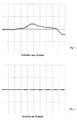
- the modulation of the ultrasound by a bubble-containing water flow is shown in FIG.
- the resonance fluctuations are caused by the wobbling of the transmitter signal minimized so that when changing the bubble size or number, none Tracking the transmission frequency is more required. So that the measurement signal obtained Can be evaluated directly with regard to the parameters of the bubble flow. Individual bubbles of the same size always lead to the same modulation when passing through the ultrasound beam, independently of such parameters as system pressure or temperature.
- the advantage of the invention is the maintenance of the optimal operation of the measuring section through the constant guarantee of repeated short-term resonance operation (at least 1000 times per second) the ultrasonic measuring device also dynamically changing flow parameters or ratios.
- a shift in the resonance frequencies by changing flow parameters therefore has only a negligibly small one Influence on the measurement signal.
- Continuous tracking of the resonance frequency is not more needed. It is therefore a universal application for ultrasound examinations for different people Purposes (e.g. ultrasonic flow measurement, determination of parameters of two and multi-phase flows) possible.
- Purposes e.g. ultrasonic flow measurement, determination of parameters of two and multi-phase flows
- For the optimal operation of the measuring purposes are only relatively simple additional devices (a sweepable function generator, an amplitude demodulator and a low pass filter) is required.
Landscapes
- Physics & Mathematics (AREA)
- Fluid Mechanics (AREA)
- General Physics & Mathematics (AREA)
- Electromagnetism (AREA)
- Measuring Volume Flow (AREA)
Description
Durch die im Rohr ablaufenden Strömungsvorgänge wird der durchgehende Schall beeinflußt, er erfährt eine Amplitudenmodulation. Nach der Rückwandlung in ein elektrisches Signal im Ultraschall-Empfänger werden diejenigen Signale, die im Bereich der Sendefrequenzen liegen, verstärkt, anschließend wird eine Amplitudendemodulation durchgeführt Das so erhaltene Signal passiert danach einen Tiefpaßfilter (höchste Paßfrequenz < Wobbelfrequenz) und steht jetzt der weiteren Meßwertverarbeitung zur Verfügung. Die Amplitude des nun vorliegenden Signales gibt, bedingt durch die Amplitudenmodulation und nachfolgende Glättung, die mittlere Änderung des Signalpegels an allen Resonanzstellen wieder, die jetzt hauptsächlich Abhängigkeiten vom durchschallten Medium aufweist Ein Einfluß von Verschiebungen einzelner Resonanzen wird durch die Mittelung über viele Resonanzstellen vermieden. Eine kontinuierliche Frequenznachführung ist somit nicht mehr erforderlich.
Durch die erfindungsgemäße Wobbelung des einschallenden Ultraschalls mit z.B. 1 kHz Wobbelfrequenz und anschließender Filterung können diese Signalfluktuationen wie in Fig. 2 gezeigt weitgehend unterdrückt werden.
Um im konkreten Anwendungsfall nicht den gesamten zur Verfügung stehenden Frequenzbereich des Ultraschallsenders durchfahren zu müssen, kann durch Beobachtung des Signalverlaufs bei ungestörtem Meßmedium der Wobbelbereich der Erregerfrequenz so lange eingeengt werden, wie die Resonanzfluktuationen unterdrückt bleiben. Im vorliegenden Beispiel ungestörten Wassers innerhalb eines Rohres wurde dieser Bereich mit 280 - 530 kHz als günstig eingegrenzt. Durch eine Tiefpaßfilterung des demodulierten Signals (f3dB = 0,1 kHz) wurde eine Mittelung über den Wobbelbereich erreicht, die den Einfluß der Verschiebung von Resonanzen stark vermindert.
Claims (2)
- Verfahren zur Minimierung des Einflusses von Resonanzfluktuationen des Meßmediums bei Ultraschall-Durchschallungsuntersuchungen an in Rohrleitungen geführten Zwei- und Mehrphasenströmungen bei denen je ein Sender und ein Empfänger für Ultraschall gegenüberliegend an der Rohrleitung angekoppelt sind und die Strömung bei Resonanzfrequenz durchschallt wird, wobei Einrichtungen zur Beeinflussung der Sendefrequenz vorgesehen sind,
dadurch gekennzeichnet, daß die Frequenz des Ultraschallsenders ständig zwischen einer definierten unteren und oberen Grenzfrequenz variiert (gewobbelt) wird, wobei die Grenzfrequenzen so definiert sind, daß für alle konkret vorkommenden Strömungsverhältnisse die Resonanzfrequenzen eingeschlossen sind, so daß während einer Wobbelperiode mindestens einmal kurzzeitig Resonanzbetrieb erreicht wird, und daß eine die Einflüsse des Wobbelns minimierende, nur die medienabhängigen Meßsignale weiterleitende Filterung des Empfängersignals erfolgt. - Verfahren nach Anspruch 1, dadurch gekennzeichnet, daß die Sendefrequenz linear oder logarithmisch variiert wird, daß nach Erreichen der Endfrequenz direkt zur Startfrequenz zurückgekehrt oder aber ein umgekehrtes wobbeln durchgeführt wird.
Applications Claiming Priority (3)
| Application Number | Priority Date | Filing Date | Title |
|---|---|---|---|
| DE4333645A DE4333645A1 (de) | 1993-10-02 | 1993-10-02 | Verfahren zur Minimierung des Einflusses von Resonanzfluktuationen auf das Meßsignal bei Ultraschall-Durchschallungsuntersuchungen |
| DE4333645 | 1993-10-02 | ||
| PCT/DE1994/001160 WO1995010027A1 (de) | 1993-10-02 | 1994-10-01 | Verfahren zur minimierung des einflusses von resonanzfluktuationen auf das messignal bei ultraschall-durchschallungsuntersuchungen |
Publications (2)
| Publication Number | Publication Date |
|---|---|
| EP0721572A1 EP0721572A1 (de) | 1996-07-17 |
| EP0721572B1 true EP0721572B1 (de) | 1999-05-19 |
Family
ID=6499270
Family Applications (1)
| Application Number | Title | Priority Date | Filing Date |
|---|---|---|---|
| EP94928284A Expired - Lifetime EP0721572B1 (de) | 1993-10-02 | 1994-10-01 | Verfahren zur minimierung des einflusses von resonanzfluktuationen auf das messignal bei ultraschall-durchschallungsuntersuchungen |
Country Status (3)
| Country | Link |
|---|---|
| EP (1) | EP0721572B1 (de) |
| DE (2) | DE4333645A1 (de) |
| WO (1) | WO1995010027A1 (de) |
Families Citing this family (1)
| Publication number | Priority date | Publication date | Assignee | Title |
|---|---|---|---|---|
| KR100516315B1 (ko) † | 1997-08-25 | 2005-09-23 | 코닌클리케 필립스 일렉트로닉스 엔.브이. | 음향 표면 타입 검출기를 가진 전기적 표면 처리 장치 |
Family Cites Families (11)
| Publication number | Priority date | Publication date | Assignee | Title |
|---|---|---|---|---|
| DE495750C (de) * | 1926-03-03 | 1930-04-24 | Richard Ambronn Dr | Verfahren zur Erderforschung mittels periodischer elastischer Wellen |
| GB1359151A (en) * | 1970-07-06 | 1974-07-10 | Coulthard J | Measurement of fluid flow rates |
| GB1373110A (en) * | 1971-01-04 | 1974-11-06 | Exxon Research Engineering Co | Fluid impurity analyzer |
| JPS5310454A (en) * | 1976-07-16 | 1978-01-30 | Nippon Kokan Kk | Apparatus for detecting change of fluid character by singgaround method |
| DE2716714A1 (de) * | 1977-04-15 | 1978-10-19 | Stern Elektronik Gmbh | Regelsystem fuer eine von einem sender und empfaenger begrenzte strahlstrecke |
| US4265125A (en) * | 1979-08-02 | 1981-05-05 | Mahany Richard J | Flowmeter method and apparatus |
| DE3141576A1 (de) * | 1981-10-20 | 1983-05-05 | Siemens AG, 1000 Berlin und 8000 München | "verfahren zur erkennung von gasblasen in einem fluessigen medium und vorrichtung zur durchfuehrung dieses verfahrens" |
| DE3601085A1 (de) * | 1986-01-16 | 1987-07-23 | Bopp & Reuther Gmbh | Vorrichtung zum messen der dichte von gasen und fluessigkeiten |
| JPS63133019A (ja) * | 1986-11-25 | 1988-06-04 | Mitsubishi Electric Corp | 流量測定装置 |
| GB8718644D0 (en) * | 1987-08-06 | 1987-10-07 | Atomic Energy Authority Uk | Temperature measurement |
| US4764166A (en) * | 1987-08-17 | 1988-08-16 | Fisher Scientific Company | Ultrasonic air-in-line detector |
-
1993
- 1993-10-02 DE DE4333645A patent/DE4333645A1/de not_active Withdrawn
-
1994
- 1994-10-01 DE DE59408288T patent/DE59408288D1/de not_active Expired - Fee Related
- 1994-10-01 WO PCT/DE1994/001160 patent/WO1995010027A1/de not_active Ceased
- 1994-10-01 EP EP94928284A patent/EP0721572B1/de not_active Expired - Lifetime
Also Published As
| Publication number | Publication date |
|---|---|
| WO1995010027A1 (de) | 1995-04-13 |
| DE4333645A1 (de) | 1995-04-06 |
| DE59408288D1 (de) | 1999-06-24 |
| EP0721572A1 (de) | 1996-07-17 |
Similar Documents
| Publication | Publication Date | Title |
|---|---|---|
| DE10206134B4 (de) | Ultraschall-Strömungsmesser | |
| DE2133393C2 (de) | Vorrichtung zum Messen der mittleren Strömungsgeschwindigkeit eines Strömungsmittels | |
| DE69529391T2 (de) | Verfahren und Vorrichtung zur Messung mittels Rundsing-Technik | |
| DE2641901C2 (de) | Verfahren und Vorrichtung zum Untersuchen von Objekten mittels Ultraschall | |
| EP0985134B1 (de) | Verfahren und vorrichtung zur messung von dichte und massenstrom | |
| DE10237980A1 (de) | Verfahren und Vorrichtung zur Ultraschallkontrolle innerhalb von Rohren | |
| DE3411446A1 (de) | Verfahren und sensor zum ermitteln einer trennflaeche einer fluessigkeit in einem behaelter | |
| DE2260932A1 (de) | Verfahren und anordnung zur bestimmung von risstiefen bei der werkstoffpruefung mit ultraschall | |
| WO1982003455A1 (fr) | Procede et dispositif pour controler et mesurer l'epaisseur de couches de matiere | |
| WO2004025227A1 (de) | Wirbelstrassen-massendurchflussmesser | |
| DE102008058376A1 (de) | Verfahren und Vorrichtung zur Fluidströmungsmessung | |
| DE102005038649A1 (de) | Verfahren und System zum Betreiben eines Ultraschallwandlers | |
| DE102022100677A1 (de) | Verfahren und Messeinrichtung zur Ermittlung einer einen Durchfluss betreffenden Messgröße | |
| DE69607175T2 (de) | Verfahren zur bestimmung von flüssigkeitseigenschaften in leitungen und zur pumpensteuerung | |
| DE3825131A1 (de) | Anordnung zur messung der konzentration von oel-wasser-mischungen | |
| DE69516316T2 (de) | Fluidischer oszillator und verfahren zur messung einer volumenmenge eines fluides das einen solchen oszillator durchströmt | |
| DE4333645A1 (de) | Verfahren zur Minimierung des Einflusses von Resonanzfluktuationen auf das Meßsignal bei Ultraschall-Durchschallungsuntersuchungen | |
| DE1798104A1 (de) | Geraet fuer die Messung der Geschwindigkeit stroemender Medien | |
| EP1563261B1 (de) | Vorrichtung zur bestimmung und/oder überwachung des volumen- und/oder des massendurchflusses eines mediums | |
| EP3812713B1 (de) | Messeinrichtung und verfahren zum betrieb einer messeinrichtung, die zur ermittlung einer fluidgrösse dient | |
| EP2407801A1 (de) | Ultraschallmesssystem für Parkhilfen von Fahrzeugen | |
| DE10353598B3 (de) | Vorrichtung und Verfahren zur Bestimmung einer Stoffkonzentration in einer Probenflüssigkeit | |
| DE102008037162A1 (de) | Verfahren und Vorrichtung zur Bestimmung des Feststoffgehaltes von Flüssigkeiten | |
| DE102024132307B3 (de) | Verfahren zum Betreiben eines Ultraschalldurchflussmessgeräts und entsprechendes Ultraschalldurchflussmessgerät | |
| DE69616999T2 (de) | Vorrichtung zur strömungsgeschwindigkeitsmessung einer flüssigkeit mittels ultraschall |
Legal Events
| Date | Code | Title | Description |
|---|---|---|---|
| PUAI | Public reference made under article 153(3) epc to a published international application that has entered the european phase |
Free format text: ORIGINAL CODE: 0009012 |
|
| 17P | Request for examination filed |
Effective date: 19960417 |
|
| AK | Designated contracting states |
Kind code of ref document: A1 Designated state(s): DE ES FR GR IT PT |
|
| 17Q | First examination report despatched |
Effective date: 19971118 |
|
| GRAG | Despatch of communication of intention to grant |
Free format text: ORIGINAL CODE: EPIDOS AGRA |
|
| GRAG | Despatch of communication of intention to grant |
Free format text: ORIGINAL CODE: EPIDOS AGRA |
|
| GRAH | Despatch of communication of intention to grant a patent |
Free format text: ORIGINAL CODE: EPIDOS IGRA |
|
| GRAH | Despatch of communication of intention to grant a patent |
Free format text: ORIGINAL CODE: EPIDOS IGRA |
|
| GRAA | (expected) grant |
Free format text: ORIGINAL CODE: 0009210 |
|
| AK | Designated contracting states |
Kind code of ref document: B1 Designated state(s): DE ES FR GR IT PT |
|
| PG25 | Lapsed in a contracting state [announced via postgrant information from national office to epo] |
Ref country code: IT Free format text: LAPSE BECAUSE OF FAILURE TO SUBMIT A TRANSLATION OF THE DESCRIPTION OR TO PAY THE FEE WITHIN THE PRESCRIBED TIME-LIMIT;WARNING: LAPSES OF ITALIAN PATENTS WITH EFFECTIVE DATE BEFORE 2007 MAY HAVE OCCURRED AT ANY TIME BEFORE 2007. THE CORRECT EFFECTIVE DATE MAY BE DIFFERENT FROM THE ONE RECORDED. Effective date: 19990519 Ref country code: GR Free format text: LAPSE BECAUSE OF NON-PAYMENT OF DUE FEES Effective date: 19990519 Ref country code: FR Free format text: LAPSE BECAUSE OF FAILURE TO SUBMIT A TRANSLATION OF THE DESCRIPTION OR TO PAY THE FEE WITHIN THE PRESCRIBED TIME-LIMIT Effective date: 19990519 Ref country code: ES Free format text: THE PATENT HAS BEEN ANNULLED BY A DECISION OF A NATIONAL AUTHORITY Effective date: 19990519 |
|
| REF | Corresponds to: |
Ref document number: 59408288 Country of ref document: DE Date of ref document: 19990624 |
|
| PG25 | Lapsed in a contracting state [announced via postgrant information from national office to epo] |
Ref country code: PT Free format text: LAPSE BECAUSE OF FAILURE TO SUBMIT A TRANSLATION OF THE DESCRIPTION OR TO PAY THE FEE WITHIN THE PRESCRIBED TIME-LIMIT Effective date: 19990819 |
|
| EN | Fr: translation not filed | ||
| PLBE | No opposition filed within time limit |
Free format text: ORIGINAL CODE: 0009261 |
|
| STAA | Information on the status of an ep patent application or granted ep patent |
Free format text: STATUS: NO OPPOSITION FILED WITHIN TIME LIMIT |
|
| 26N | No opposition filed | ||
| PGFP | Annual fee paid to national office [announced via postgrant information from national office to epo] |
Ref country code: DE Payment date: 20001004 Year of fee payment: 7 |
|
| PG25 | Lapsed in a contracting state [announced via postgrant information from national office to epo] |
Ref country code: DE Free format text: LAPSE BECAUSE OF NON-PAYMENT OF DUE FEES Effective date: 20020702 |